EP1772897A2 - Plasma lighting system having thin metallic film resonator - Google Patents
Plasma lighting system having thin metallic film resonator Download PDFInfo
- Publication number
- EP1772897A2 EP1772897A2 EP06020841A EP06020841A EP1772897A2 EP 1772897 A2 EP1772897 A2 EP 1772897A2 EP 06020841 A EP06020841 A EP 06020841A EP 06020841 A EP06020841 A EP 06020841A EP 1772897 A2 EP1772897 A2 EP 1772897A2
- Authority
- EP
- European Patent Office
- Prior art keywords
- metallic film
- thin metallic
- resonator
- lighting system
- electrodeless bulb
- Prior art date
- Legal status (The legal status is an assumption and is not a legal conclusion. Google has not performed a legal analysis and makes no representation as to the accuracy of the status listed.)
- Withdrawn
Links
- 230000002093 peripheral effect Effects 0.000 claims abstract description 25
- 239000000463 material Substances 0.000 claims abstract description 21
- RYGMFSIKBFXOCR-UHFFFAOYSA-N Copper Chemical compound [Cu] RYGMFSIKBFXOCR-UHFFFAOYSA-N 0.000 claims description 5
- BQCADISMDOOEFD-UHFFFAOYSA-N Silver Chemical compound [Ag] BQCADISMDOOEFD-UHFFFAOYSA-N 0.000 claims description 5
- 229910052782 aluminium Inorganic materials 0.000 claims description 5
- XAGFODPZIPBFFR-UHFFFAOYSA-N aluminium Chemical compound [Al] XAGFODPZIPBFFR-UHFFFAOYSA-N 0.000 claims description 5
- 229910052802 copper Inorganic materials 0.000 claims description 5
- 239000010949 copper Substances 0.000 claims description 5
- 239000011521 glass Substances 0.000 claims description 5
- PCHJSUWPFVWCPO-UHFFFAOYSA-N gold Chemical compound [Au] PCHJSUWPFVWCPO-UHFFFAOYSA-N 0.000 claims description 5
- 229910052737 gold Inorganic materials 0.000 claims description 5
- 239000010931 gold Substances 0.000 claims description 5
- 229910052709 silver Inorganic materials 0.000 claims description 5
- 239000004332 silver Substances 0.000 claims description 5
- 229910052751 metal Inorganic materials 0.000 claims description 4
- 239000002184 metal Substances 0.000 claims description 4
- 230000000903 blocking effect Effects 0.000 abstract description 3
- 239000010408 film Substances 0.000 description 48
- 230000008878 coupling Effects 0.000 description 4
- 238000010168 coupling process Methods 0.000 description 4
- 238000005859 coupling reaction Methods 0.000 description 4
- 239000011261 inert gas Substances 0.000 description 4
- 238000002834 transmittance Methods 0.000 description 4
- 238000010276 construction Methods 0.000 description 3
- 239000000945 filler Substances 0.000 description 3
- 239000007789 gas Substances 0.000 description 3
- 230000007257 malfunction Effects 0.000 description 3
- 238000004519 manufacturing process Methods 0.000 description 3
- 239000010409 thin film Substances 0.000 description 3
- XKRFYHLGVUSROY-UHFFFAOYSA-N Argon Chemical compound [Ar] XKRFYHLGVUSROY-UHFFFAOYSA-N 0.000 description 2
- 238000001816 cooling Methods 0.000 description 2
- 238000000295 emission spectrum Methods 0.000 description 2
- BUGBHKTXTAQXES-UHFFFAOYSA-N Selenium Chemical compound [Se] BUGBHKTXTAQXES-UHFFFAOYSA-N 0.000 description 1
- 229910000831 Steel Inorganic materials 0.000 description 1
- NINIDFKCEFEMDL-UHFFFAOYSA-N Sulfur Chemical compound [S] NINIDFKCEFEMDL-UHFFFAOYSA-N 0.000 description 1
- 239000005864 Sulphur Substances 0.000 description 1
- 229910052786 argon Inorganic materials 0.000 description 1
- 230000005540 biological transmission Effects 0.000 description 1
- 230000003247 decreasing effect Effects 0.000 description 1
- 230000000694 effects Effects 0.000 description 1
- 150000002366 halogen compounds Chemical class 0.000 description 1
- 238000009434 installation Methods 0.000 description 1
- 229910052743 krypton Inorganic materials 0.000 description 1
- DNNSSWSSYDEUBZ-UHFFFAOYSA-N krypton atom Chemical compound [Kr] DNNSSWSSYDEUBZ-UHFFFAOYSA-N 0.000 description 1
- QSHDDOUJBYECFT-UHFFFAOYSA-N mercury Chemical compound [Hg] QSHDDOUJBYECFT-UHFFFAOYSA-N 0.000 description 1
- 229910052753 mercury Inorganic materials 0.000 description 1
- 230000004048 modification Effects 0.000 description 1
- 238000012986 modification Methods 0.000 description 1
- 230000003287 optical effect Effects 0.000 description 1
- 239000010453 quartz Substances 0.000 description 1
- 229910052711 selenium Inorganic materials 0.000 description 1
- 239000011669 selenium Substances 0.000 description 1
- VYPSYNLAJGMNEJ-UHFFFAOYSA-N silicon dioxide Inorganic materials O=[Si]=O VYPSYNLAJGMNEJ-UHFFFAOYSA-N 0.000 description 1
- 239000002904 solvent Substances 0.000 description 1
- 238000001228 spectrum Methods 0.000 description 1
- 239000010959 steel Substances 0.000 description 1
- 230000001131 transforming effect Effects 0.000 description 1
Images




Classifications
-
- H—ELECTRICITY
- H01—ELECTRIC ELEMENTS
- H01J—ELECTRIC DISCHARGE TUBES OR DISCHARGE LAMPS
- H01J65/00—Lamps without any electrode inside the vessel; Lamps with at least one main electrode outside the vessel
- H01J65/04—Lamps in which a gas filling is excited to luminesce by an external electromagnetic field or by external corpuscular radiation, e.g. for indicating plasma display panels
- H01J65/042—Lamps in which a gas filling is excited to luminesce by an external electromagnetic field or by external corpuscular radiation, e.g. for indicating plasma display panels by an external electromagnetic field
- H01J65/044—Lamps in which a gas filling is excited to luminesce by an external electromagnetic field or by external corpuscular radiation, e.g. for indicating plasma display panels by an external electromagnetic field the field being produced by a separate microwave unit
-
- H—ELECTRICITY
- H01—ELECTRIC ELEMENTS
- H01P—WAVEGUIDES; RESONATORS, LINES, OR OTHER DEVICES OF THE WAVEGUIDE TYPE
- H01P7/00—Resonators of the waveguide type
- H01P7/06—Cavity resonators
-
- H—ELECTRICITY
- H05—ELECTRIC TECHNIQUES NOT OTHERWISE PROVIDED FOR
- H05B—ELECTRIC HEATING; ELECTRIC LIGHT SOURCES NOT OTHERWISE PROVIDED FOR; CIRCUIT ARRANGEMENTS FOR ELECTRIC LIGHT SOURCES, IN GENERAL
- H05B41/00—Circuit arrangements or apparatus for igniting or operating discharge lamps
- H05B41/14—Circuit arrangements
- H05B41/24—Circuit arrangements in which the lamp is fed by high frequency AC, or with separate oscillator frequency
Definitions
- the present invention relates to a plasma lighting system having a thin metallic film resonator, and more particularly, to a plasma lighting system having a thin metallic film resonator, which can raise the luminous efficiency of an electrodeless bulb by increasing the amount of microwaves to be focused on the electrodeless bulb, and which can avoid malfunctions of other external devices in the same frequency band by preventing microwaves from leaking out of the resonator.
- a plasma lighting system is a lighting system in which microwave energy generated from a magnetron, a microwave generator, is transmitted to a resonator through a waveguide, and is applied to an electrodeless bulb installed in the resonator so that gas filled in the electrodeless bulb is excited and converted into a plasma state to generate light.
- the electrodeless bulb does not include an electrode or a filament therein, thus the plasma lighting system has longer or semipermanent life span.
- the filler material filled in the electrodeless bulb emit light by being transformed into a plasma state to thus generate light that closely resembles natural light.
- FIG. 1 is a plane view showing a structure of a conventional plasma lighting system.
- FIG. 2 is a line cross-sectional view taken along line II-II of FIG. 1.
- the conventional plasma lighting system includes: a high voltage generator 20 generating a high voltage when electric power is applied to an inner space of a casing 10; a microwave generator 30 generating a microwave having a high frequency when the high voltage generated from the high voltage generator 20 is applied; a waveguide 40 guiding the microwave applied from the microwave generator 30; a resonator 50 provided outside the casing, for shielding the microwave guided by the waveguide 40 from being leaked out to provide a resonance mode; and an electrodeless bulb 60 rotatably arranged at the center of the resonator 50, for generating light by transforming inert gas enclosed therein into a plasma state.
- the waveguide 40 is a cylindrical tube, whose one side is connected to the microwave generator 30.
- a resonator coupling member 41 having a predetermined height is protruded on the upper end face of the waveguide 40 along the height direction of the waveguide 40.
- the resonator coupling member 41 is formed in a ring shape having a smaller diameter than the waveguide 40, the center of which is penetrated at the center, and an outer surface of which is fixed and coupled to the resonator 50.
- the resonator 50 is formed of a cylindrical mesh 51 having a net structure so that the electrodeless bulb 60 is housed in an inner space, the microwave is blocked from being leaked out and then transmitted to the electrodeless bulb 60, and the light generated from the electrodeless bulb 60 can be transmitted to the outside.
- the outer profile of the resonator 50 is formed of steel so as to maintain its cylindrical form.
- a mirror 70 is formed in a disc shape having the same diameter as the resonator coupling member 41, and arranged so as to be in contact with the upper end face of the resonator coupling member 41.
- the electrodeless bulb 60 is provided at the center of the mirror 70 so as to extend to a predetermined length along the height direction of the waveguide 40 and be exposed to the outside of the waveguide 40.
- the electrodeless bulb 60 includes a bulb-shaped luminous unit 61 having a predetermined inner volume in which a filler material is enclosed, and a fixing unit 62 extended integral with the luminous unit 61 and formed of the same material as the luminous unit 61.
- the luminous unit 61 is installed inside the casing 10, and the fixing unit 62 is installed to penetrate through the center portion of the waveguide 40.
- the fixing unit 62 installed together with the luminous unit 61 is connected to a motor shaft of a driving motor 90 installed in the casing 10 and rotates at a predetermined speed.
- the luminous unit 61 is mainly made of a material, such as quartz, having a high transmittance and an extremely small dielectric loss.
- the filler material to be enclosed in the luminous unit 61 is mainly made of luminous materials, such as metal, halogen compound, sulphur, and selenium, inert gases, such as argon gas and krypton gas, for forming plasma in the luminous unit 61, and discharge solvent materials, such as mercury, for making lighting easier by assisting an initial discharge or controlling the spectrum of generated light or the like.
- unexplained reference numerals 70 denotes a mirror
- 80 denotes a reflecting shade
- 100 denotes a cooling fan
- 110 denotes a second driving motor for rotating the cooling fan
- 120 denotes an air duct.
- the high voltage generator 20 when a driving signal is inputted to the high voltage generator 20, the high voltage generator 20 raises AC power and supplies the raised high voltage to the microwave generator 30.
- the microwave generator 30 oscillates by a high voltage to thereby generate microwaves having a very high frequency.
- the microwaves are emitted into the resonator 50 through the waveguide 40, and then the inert gas filled in the electrodeless bulb 60 is excited to continually transform the luminous material into a plasma state so as to emit light having an intrinsic emission spectrum.
- the light reaches the surface of the mirror 70 arranged at the rear side of the electrodeless bulb 60 and is reflected on the front side of the electrodeless bulb 60, thereby lighting a space.
- an object of the present invention is to provide a plasma lighting system having a thin metallic film resonator, which can raise the luminous efficiency of an electrodeless bulb by increasing the amount of microwaves to be focused on the electrodeless bulb, and which can avoid malfunctions of other external devices in the same frequency band by preventing microwaves from leaking out of the resonator.
- a plasma lighting system having a thin metallic film resonator, including: an electrodeless bulb emitting light by making luminous material filled therein converted into plasma state; and a resonator housing the electrodeless bulb in an inner space, transmitting the light generated from the electrodeless bulb, and blocking the microwave generated from a microwave generator and applied to the inner space from being leaked out so that a resonance mode is provided to make the electrodeless bulb emit light, wherein the resonator is a thin metallic film resonator including a thin metallic film formed in a cylindrical shape and a supporting member extended along the inner peripheral surface of the thin metallic film so as to support the thin metallic film.
- the thin metallic film is formed of any one metal of gold, silver, copper, and aluminum.
- the supporting member is preferably formed of a glass material.
- a cylindrical thin metallic film is further provided on the inner peripheral surface of the supporting member.
- a mesh type resonator having a cylindrical porous mesh structure is further provided on the inner peripheral surface of the thin metallic film resonator.
- a mesh type resonator having a cylindrical porous mesh structure is further provided on the outer peripheral surface of the thin metallic film resonator.
- FIG. 3 is a cross sectional view of a plasma lighting system having a thin metallic film resonator in accordance with one embodiment of the present invention.
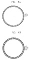
- FIGs. 4A and 4B are line cross sectional views taken along line IV-IV of FIG. 3.
- FIGs. 5A through 5C are cross sectional views of a plasma lighting system having a thin metallic film resonator in accordance with another embodiment of the present invention.
- FIGs. 6A through 6C are cross sectional views of a plasma lighting system having a thin metallic film resonator in accordance with still another embodiment of the present invention.
- a plasma lighting system having a thin metallic film resonator in accordance with one embodiment of the present invention includes: an electrodeless bulb 60 emitting light by making luminous material filled therein converted into plasma state; and a resonator 50 housing the electrodeless bulb 60 in an inner space, transmitting the light generated from the electrodeless bulb 60, and blocking the microwave generated from a microwave generator 30 applied to the inner space from being leaked out so that a resonance mode is provided to make the electrodeless bulb emit light, wherein the resonator 50 includes a thin metallic film 52 formed in a cylindrical shape and a supporting member 53 extended along the inner peripheral surface of the thin metallic film 52 so as to support the thin metallic film 52.
- the thin metallic film transistor in accordance with one embodiment of the present invention includes a thin metallic film 52 formed in a cylindrical shape and a supporting member 53 provided on the inner peripheral surface or outer peripheral surface of the thin metallic film 52 so as to allow the thin metallic film 52 to maintain a cylindrical shape.
- the thin metallic film 52 is implemented in a thin film made of a material having a high conductivity, such as gold, silver, copper, and aluminum, openings provided at the conventional mesh 51 type resonator 50 are not required.
- the supporting member 53 is formed of a material, such as glass, with less light loss and good transmittance of light.
- the thin metallic film transistor in accordance with another embodiment of the present invention includes a thin metallic film 52 formed in a cylindrical shape, a supporting member 53 provided on the inner peripheral surface or outer peripheral surface of the thin metallic film 52 so as to allow the thin metallic film 52 to maintain a cylindrical shape, and a mesh 51 type resonator 50 provided on the inner peripheral surface of the supporting member 53.
- the thin metallic film 52 is implemented in a thin film made of a material having a high conductivity, such as gold, silver, copper, and aluminum, openings provided at the conventional mesh 51 type resonator 50 are not required.
- the supporting member 53 is formed of a material, such as glass, with less light loss and good transmittance of light.
- the thin metallic film 52 may be installed dually on the inner peripheral surface and outer peripheral surface of the supporting member 53.
- the mesh 51 type resonator 50 is installed on the inner peripheral surface of the supporting member 53, it is contacted with the plate surface of the thin metallic film 52 and the plate surface of the mesh 51 type resonator 50 to thus increase the conductivity therebetween, thereby making it easy to provide a resonance mode of the resonator 50.
- the thin metallic film transistor in accordance with still another embodiment of the present invention includes a thin metallic film 52 formed in a cylindrical shape, a supporting member 53 provided on the inner peripheral surface or outer peripheral surface of the thin metallic film 52 so as to allow the thin metallic film 52 to maintain a cylindrical shape, and a mesh 51 type resonator 50 provided on the outer peripheral surface of the supporting member 53.
- the thin metallic film 52 is implemented in a thin film made of a material having a high conductivity, such as gold, silver, copper, and aluminum, openings provided at the conventional mesh 51 type resonator 50 are not required.
- the supporting member 53 is formed of a material, such as glass, with less light loss and good transmittance of light.
- the thin metallic film 52 may be installed dually on the inner peripheral surface and outer peripheral surface of the supporting member 53.
- the installation of the mesh 51 type resonator 50 on the outer peripheral surface of the supporting member 53 does not provided the effect of maintaining conductivity by contact with the plate surface of the thin metallic film 52 and the plate surface of the mesh 51 type resonator 50, it has the advantage that it is easy to manufacture a resonator in the manufacture of a plasma lighting system because the mesh 51 type resonator 50 is of such a structure as to be exposed to the outside.
- the high voltage generator 20 when a driving signal is inputted to the high voltage generator 20, the high voltage generator 20 raises AC power and supplies the raised high voltage to the microwave generator 30.
- the microwave generator 30 oscillates by a high voltage to thereby generate microwaves having a very high frequency.
- the microwaves are emitted into the resonator 50 through the waveguide 40, and then the inert gas filled in the electrodeless bulb 60 is excited to continually transform the luminous material into a plasma state.
- the thin metallic film 52 of the resonator 50 has a thickness of several micrometers ( ⁇ m), which is very thin, thus it has the characteristic that light is transmitted and most parts of microwaves are reflected so that the microwaves can be prevented from being leaked out.
- the electrodeless bulb 50 having received such a microwave energy generates light having an intrinsic emission spectrum.
- the light reaches the surface of the mirror 70 arranged at the rear side of the electrodeless bulb 60 and is reflected on the front side of the electrodeless bulb 60, thereby lighting a space.
Landscapes
- Physics & Mathematics (AREA)
- Electromagnetism (AREA)
- Engineering & Computer Science (AREA)
- Plasma & Fusion (AREA)
- Non-Portable Lighting Devices Or Systems Thereof (AREA)
- Discharge Lamps And Accessories Thereof (AREA)
Abstract
A plasma lighting system having a thin metallic film resonator includes: an electrodeless bulb emitting light by making luminous material filled therein converted into plasma state; and a resonator housing the electrodeless bulb in an inner space, transmitting the light generated from the electrodeless bulb, and blocking the microwave generated from a microwave generator and applied to the inner space from being leaked out so that a resonance mode is provided to make the electrodeless bulb emit light, wherein the resonator is a thin metallic film resonator including a thin metallic film formed in a cylindrical shape and a supporting member extended along the inner peripheral surface of the thin metallic film so as to support the thin metallic film.
Description
- The present disclosure relates to subject matter contained in priority
Korean Application No. 10-2003-0085274, filed on November 27, 2003 - The present invention relates to a plasma lighting system having a thin metallic film resonator, and more particularly, to a plasma lighting system having a thin metallic film resonator, which can raise the luminous efficiency of an electrodeless bulb by increasing the amount of microwaves to be focused on the electrodeless bulb, and which can avoid malfunctions of other external devices in the same frequency band by preventing microwaves from leaking out of the resonator.
- Generally, a plasma lighting system is a lighting system in which microwave energy generated from a magnetron, a microwave generator, is transmitted to a resonator through a waveguide, and is applied to an electrodeless bulb installed in the resonator so that gas filled in the electrodeless bulb is excited and converted into a plasma state to generate light.
- The electrodeless bulb does not include an electrode or a filament therein, thus the plasma lighting system has longer or semipermanent life span. The filler material filled in the electrodeless bulb emit light by being transformed into a plasma state to thus generate light that closely resembles natural light.
- FIG. 1 is a plane view showing a structure of a conventional plasma lighting system. FIG. 2 is a line cross-sectional view taken along line II-II of FIG. 1.
- As shown therein, the conventional plasma lighting system includes: a
high voltage generator 20 generating a high voltage when electric power is applied to an inner space of acasing 10; amicrowave generator 30 generating a microwave having a high frequency when the high voltage generated from thehigh voltage generator 20 is applied; awaveguide 40 guiding the microwave applied from themicrowave generator 30; aresonator 50 provided outside the casing, for shielding the microwave guided by thewaveguide 40 from being leaked out to provide a resonance mode; and anelectrodeless bulb 60 rotatably arranged at the center of theresonator 50, for generating light by transforming inert gas enclosed therein into a plasma state. - The
waveguide 40 is a cylindrical tube, whose one side is connected to themicrowave generator 30. Aresonator coupling member 41 having a predetermined height is protruded on the upper end face of thewaveguide 40 along the height direction of thewaveguide 40. - The
resonator coupling member 41 is formed in a ring shape having a smaller diameter than thewaveguide 40, the center of which is penetrated at the center, and an outer surface of which is fixed and coupled to theresonator 50. - The
resonator 50 is formed of acylindrical mesh 51 having a net structure so that theelectrodeless bulb 60 is housed in an inner space, the microwave is blocked from being leaked out and then transmitted to theelectrodeless bulb 60, and the light generated from theelectrodeless bulb 60 can be transmitted to the outside. The outer profile of theresonator 50 is formed of steel so as to maintain its cylindrical form. - A
mirror 70 is formed in a disc shape having the same diameter as theresonator coupling member 41, and arranged so as to be in contact with the upper end face of theresonator coupling member 41. Theelectrodeless bulb 60 is provided at the center of themirror 70 so as to extend to a predetermined length along the height direction of thewaveguide 40 and be exposed to the outside of thewaveguide 40. - Meanwhile, the
electrodeless bulb 60 includes a bulb-shapedluminous unit 61 having a predetermined inner volume in which a filler material is enclosed, and afixing unit 62 extended integral with theluminous unit 61 and formed of the same material as theluminous unit 61. - The
luminous unit 61 is installed inside thecasing 10, and thefixing unit 62 is installed to penetrate through the center portion of thewaveguide 40. Thefixing unit 62 installed together with theluminous unit 61 is connected to a motor shaft of a drivingmotor 90 installed in thecasing 10 and rotates at a predetermined speed. - Preferably, the
luminous unit 61 is mainly made of a material, such as quartz, having a high transmittance and an extremely small dielectric loss. The filler material to be enclosed in theluminous unit 61 is mainly made of luminous materials, such as metal, halogen compound, sulphur, and selenium, inert gases, such as argon gas and krypton gas, for forming plasma in theluminous unit 61, and discharge solvent materials, such as mercury, for making lighting easier by assisting an initial discharge or controlling the spectrum of generated light or the like. - In the drawings,
unexplained reference numerals 70 denotes a mirror, 80 denotes a reflecting shade, 100 denotes a cooling fan, 110 denotes a second driving motor for rotating the cooling fan, and 120 denotes an air duct. - According to the above-said construction of the conventional plasma lighting system, when a driving signal is inputted to the
high voltage generator 20, thehigh voltage generator 20 raises AC power and supplies the raised high voltage to themicrowave generator 30. Themicrowave generator 30 oscillates by a high voltage to thereby generate microwaves having a very high frequency. - The microwaves are emitted into the
resonator 50 through thewaveguide 40, and then the inert gas filled in theelectrodeless bulb 60 is excited to continually transform the luminous material into a plasma state so as to emit light having an intrinsic emission spectrum. The light reaches the surface of themirror 70 arranged at the rear side of theelectrodeless bulb 60 and is reflected on the front side of theelectrodeless bulb 60, thereby lighting a space. - However, in such a conventional plasma lighting system, if the microwaves generated in the
microwave generator 30 are guided by thewaveguide 40 to provide a resonance mode inside theresonator 50, parts of the microwaves are leaked out via openings of themesh 51 of theresonator 50 and thus, the amount of microwaves to be focused on theelectrodeless bulb 60 is reduced, thereby decreasing the optical efficiency of theelectrodeless bulb 60. Further, malfunctions may occurred to other external devices in the same frequency band with the leaked microwaves. - Therefore, an object of the present invention is to provide a plasma lighting system having a thin metallic film resonator, which can raise the luminous efficiency of an electrodeless bulb by increasing the amount of microwaves to be focused on the electrodeless bulb, and which can avoid malfunctions of other external devices in the same frequency band by preventing microwaves from leaking out of the resonator.
- To achieve these and other advantages and in accordance with the purpose of the present invention, as embodied and broadly described herein, there is provided a plasma lighting system having a thin metallic film resonator, including: an electrodeless bulb emitting light by making luminous material filled therein converted into plasma state; and a resonator housing the electrodeless bulb in an inner space, transmitting the light generated from the electrodeless bulb, and blocking the microwave generated from a microwave generator and applied to the inner space from being leaked out so that a resonance mode is provided to make the electrodeless bulb emit light, wherein the resonator is a thin metallic film resonator including a thin metallic film formed in a cylindrical shape and a supporting member extended along the inner peripheral surface of the thin metallic film so as to support the thin metallic film.
- It is effective that the thin metallic film is formed of any one metal of gold, silver, copper, and aluminum.
- This is to easily provide a resonance mode in the resonator and to increase the amount of microwaves to be focused on the electrodeless bulb by forming the thin metallic film from a metal having a high conductivity.
- Furthermore, the supporting member is preferably formed of a glass material.
- This is to transmit light generated from the electrodeless bulb to the outside and to reduce the loss of light at the time of transmission.
- Furthermore, it is effective that a cylindrical thin metallic film is further provided on the inner peripheral surface of the supporting member.
- This is to reduce the amount of microwaves to be leaked out of the resonator by providing a thin metallic film dually on the inner and outer peripheral surfaces of the supporting member around the supporting member.
- Moreover, it is effective that a mesh type resonator having a cylindrical porous mesh structure is further provided on the inner peripheral surface of the thin metallic film resonator.
- This is to easily provide a resonance mode in the resonator and to increase the amount of microwaves to be focused on the electrodeless bulb by contacting the thin metallic film and the mesh type resonator and improving the conductivity therebetween.
- Preferably, a mesh type resonator having a cylindrical porous mesh structure is further provided on the outer peripheral surface of the thin metallic film resonator.
- This is to easily install the mesh type resonator on the thin metallic film resonator in manufacturing the plasma lighting system.
- The foregoing and other objects, features, aspects and advantages of the present invention will become more apparent from the following detailed description of the present invention when taken in conjunction with the accompanying drawings.
- The accompanying drawings, which are included to provide a further understanding of the invention and are incorporated in and constitute a part of this specification, illustrate embodiments of the invention and together with the description serve to explain the principles of the invention.
- In the drawings:
- FIG. 1 is a plane view showing a structure of a conventional plasma lighting system;
- FIG. 2 is a line cross-sectional view taken along line II-II of FIG. 1;
- FIG. 3 is a cross sectional view of a plasma lighting system having a thin metallic film resonator in accordance with one embodiment of the present invention;
- FIGs. 4A and 4B are line cross sectional views taken along line IV-IV of FIG. 3;
- FIGs. 5A through 5C are cross sectional views of a plasma lighting system having a thin metallic film resonator in accordance with another embodiment of the present invention; and
- FIGs. 6A through 6C are cross sectional views of a plasma lighting system having a thin metallic film resonator in accordance with still another embodiment of the present invention.
- Hereinafter, the present invention will be described in detail with reference to the accompanying drawings.
- Like reference numerals are used to designate like elements of the conventional construction, and a detailed description thereof will be omitted.
- FIG. 3 is a cross sectional view of a plasma lighting system having a thin metallic film resonator in accordance with one embodiment of the present invention. FIGs. 4A and 4B are line cross sectional views taken along line IV-IV of FIG. 3. FIGs. 5A through 5C are cross sectional views of a plasma lighting system having a thin metallic film resonator in accordance with another embodiment of the present invention. FIGs. 6A through 6C are cross sectional views of a plasma lighting system having a thin metallic film resonator in accordance with still another embodiment of the present invention.
- As shown in these drawings, a plasma lighting system having a thin metallic film resonator in accordance with one embodiment of the present invention includes: an
electrodeless bulb 60 emitting light by making luminous material filled therein converted into plasma state; and aresonator 50 housing theelectrodeless bulb 60 in an inner space, transmitting the light generated from theelectrodeless bulb 60, and blocking the microwave generated from amicrowave generator 30 applied to the inner space from being leaked out so that a resonance mode is provided to make the electrodeless bulb emit light, wherein theresonator 50 includes a thinmetallic film 52 formed in a cylindrical shape and a supportingmember 53 extended along the inner peripheral surface of the thinmetallic film 52 so as to support the thinmetallic film 52. - As shown in FIGS. 4A and 4B, the thin metallic film transistor in accordance with one embodiment of the present invention includes a thin
metallic film 52 formed in a cylindrical shape and a supportingmember 53 provided on the inner peripheral surface or outer peripheral surface of the thinmetallic film 52 so as to allow the thinmetallic film 52 to maintain a cylindrical shape. - Since the thin
metallic film 52 is implemented in a thin film made of a material having a high conductivity, such as gold, silver, copper, and aluminum, openings provided at theconventional mesh 51type resonator 50 are not required. - The supporting
member 53 is formed of a material, such as glass, with less light loss and good transmittance of light. - As shown in FIGs. 5A through 5C, the thin metallic film transistor in accordance with another embodiment of the present invention includes a thin
metallic film 52 formed in a cylindrical shape, a supportingmember 53 provided on the inner peripheral surface or outer peripheral surface of the thinmetallic film 52 so as to allow the thinmetallic film 52 to maintain a cylindrical shape, and amesh 51type resonator 50 provided on the inner peripheral surface of the supportingmember 53. - Since the thin
metallic film 52 is implemented in a thin film made of a material having a high conductivity, such as gold, silver, copper, and aluminum, openings provided at theconventional mesh 51type resonator 50 are not required. - The supporting
member 53 is formed of a material, such as glass, with less light loss and good transmittance of light. In order to prevent the microwave applied into theresonator 50 from being leaked out of theresonator 50, the thinmetallic film 52 may be installed dually on the inner peripheral surface and outer peripheral surface of the supportingmember 53. - If the
mesh 51type resonator 50 is installed on the inner peripheral surface of the supportingmember 53, it is contacted with the plate surface of the thinmetallic film 52 and the plate surface of themesh 51type resonator 50 to thus increase the conductivity therebetween, thereby making it easy to provide a resonance mode of theresonator 50. - As shown in FIGs. 6A through 6C, the thin metallic film transistor in accordance with still another embodiment of the present invention includes a thin
metallic film 52 formed in a cylindrical shape, a supportingmember 53 provided on the inner peripheral surface or outer peripheral surface of the thinmetallic film 52 so as to allow the thinmetallic film 52 to maintain a cylindrical shape, and amesh 51type resonator 50 provided on the outer peripheral surface of the supportingmember 53. - Since the thin
metallic film 52 is implemented in a thin film made of a material having a high conductivity, such as gold, silver, copper, and aluminum, openings provided at theconventional mesh 51type resonator 50 are not required. - The supporting
member 53 is formed of a material, such as glass, with less light loss and good transmittance of light. In order to prevent the microwave applied into theresonator 50 from being leaked out of theresonator 50, the thinmetallic film 52 may be installed dually on the inner peripheral surface and outer peripheral surface of the supportingmember 53. - Though the installation of the
mesh 51type resonator 50 on the outer peripheral surface of the supportingmember 53 does not provided the effect of maintaining conductivity by contact with the plate surface of the thinmetallic film 52 and the plate surface of themesh 51type resonator 50, it has the advantage that it is easy to manufacture a resonator in the manufacture of a plasma lighting system because themesh 51type resonator 50 is of such a structure as to be exposed to the outside. - According to the above-said construction of the plasma lighting system having a thin metallic film resonator in accordance with the present invention, when a driving signal is inputted to the
high voltage generator 20, thehigh voltage generator 20 raises AC power and supplies the raised high voltage to themicrowave generator 30. Themicrowave generator 30 oscillates by a high voltage to thereby generate microwaves having a very high frequency. - The microwaves are emitted into the
resonator 50 through thewaveguide 40, and then the inert gas filled in theelectrodeless bulb 60 is excited to continually transform the luminous material into a plasma state. At this point, the thinmetallic film 52 of theresonator 50 has a thickness of several micrometers (µm), which is very thin, thus it has the characteristic that light is transmitted and most parts of microwaves are reflected so that the microwaves can be prevented from being leaked out. By forming acylindrical resonator 50 using such a thinmetallic film 52, the microwaves in theresonator 50 are reflected inside theresonator 50 and focused on theelectrodeless bulb 60, thereby transmitting a microwave energy to theelectrodeless bulb 60. - The
electrodeless bulb 50 having received such a microwave energy generates light having an intrinsic emission spectrum. The light reaches the surface of themirror 70 arranged at the rear side of theelectrodeless bulb 60 and is reflected on the front side of theelectrodeless bulb 60, thereby lighting a space. - As the present invention may be embodied in several forms without departing from the spirit or essential characteristics thereof, it should also be understood that the above-described embodiments are not limited by any of the details of the foregoing description, unless otherwise specified, but rather should be construed broadly within its spirit and scope as defined in the appended claims, and therefore all changes and modifications that fall within the metes and bounds of the claims, or equivalents of such metes and bounds are therefore intended to be embraced by the appended claims.
Claims (6)
- A plasma lighting system having a thin metallic film resonator, comprising:an electrodeless bulb emitting light by making luminous material filled therein converted into plasma state; anda thin metallic film resonator provided with a cylindrical thin metallic film housing the electrodeless bulb in an inner space and forming a resonance mode, and a supporting member extended along an inner peripheral surface of the thin metallic film so as to support the thin metallic film.
- The plasma lighting system of claim 1, wherein the thin metallic film is formed of any one metal having a high conductivity of gold, silver, copper, and aluminum.
- The plasma lighting system of claim 1 or 2, wherein the supporting member is formed of a glass material which can transmit light and shows less loss of transmitted light.
- The plasma lighting system of any of claims 1 to 3, wherein a cylindrical thin metallic film is further provided on the inner peripheral surface of the supporting member.
- The plasma lighting system of any of claims 1 to 4, wherein a mesh type resonator having a cylindrical porous mesh structure is further provided on the inner peripheral surface of the thin metallic film resonator.
- The plasma lighting system of any of claims 1 to 4, wherein a mesh type resonator having a cylindrical porous mesh structure is further provided on the outer peripheral surface of the thin metallic film resonator.
Applications Claiming Priority (1)
| Application Number | Priority Date | Filing Date | Title |
|---|---|---|---|
| KR1020050093581A KR100748531B1 (en) | 2005-10-05 | 2005-10-05 | Electrodeless illuminator with metal thin film resonator |
Publications (1)
| Publication Number | Publication Date |
|---|---|
| EP1772897A2 true EP1772897A2 (en) | 2007-04-11 |
Family
ID=37452452
Family Applications (1)
| Application Number | Title | Priority Date | Filing Date |
|---|---|---|---|
| EP06020841A Withdrawn EP1772897A2 (en) | 2005-10-05 | 2006-10-04 | Plasma lighting system having thin metallic film resonator |
Country Status (4)
| Country | Link |
|---|---|
| US (1) | US7622856B2 (en) |
| EP (1) | EP1772897A2 (en) |
| KR (1) | KR100748531B1 (en) |
| CN (1) | CN1945790A (en) |
Families Citing this family (2)
| Publication number | Priority date | Publication date | Assignee | Title |
|---|---|---|---|---|
| CN103341236A (en) * | 2013-07-10 | 2013-10-09 | 宋本庆 | High-concentration photon radiation therapeutic machine used for treating skin diseases, skin burns and scalds |
| CN103715059B (en) * | 2014-01-02 | 2016-02-10 | 长乐芯聚电子科技研究所 | High brightness microwave lamp |
Family Cites Families (8)
| Publication number | Priority date | Publication date | Assignee | Title |
|---|---|---|---|---|
| JPH10321039A (en) * | 1997-05-15 | 1998-12-04 | Matsushita Electron Corp | Microwave discharge lamp device |
| KR100314016B1 (en) * | 1999-08-31 | 2001-11-17 | 구자홍 | The resonator structure for microwave lighting system |
| KR100364545B1 (en) * | 2000-12-18 | 2002-12-18 | 엘지전자 주식회사 | Apparatus to protect resonator for the microwave lighting system |
| KR100404474B1 (en) * | 2001-11-23 | 2003-11-05 | 주식회사 엘지이아이 | Resonator structure for microwave lighting system and method thereof |
| KR100404470B1 (en) * | 2001-11-23 | 2003-11-05 | 주식회사 엘지이아이 | Resonator structure for microwave lighting system |
| JP2003249196A (en) * | 2002-02-25 | 2003-09-05 | Matsushita Electric Works Ltd | Microwave electrodeless discharge lamp lighting device |
| KR100677277B1 (en) | 2005-05-11 | 2007-02-02 | 엘지전자 주식회사 | Electrodeless lamp system |
| KR102004857B1 (en) | 2018-11-05 | 2019-07-29 | 주식회사 스틸네트워크 | Loosening prevention nut |
-
2005
- 2005-10-05 KR KR1020050093581A patent/KR100748531B1/en not_active Expired - Fee Related
-
2006
- 2006-09-27 US US11/535,612 patent/US7622856B2/en not_active Expired - Fee Related
- 2006-10-04 EP EP06020841A patent/EP1772897A2/en not_active Withdrawn
- 2006-10-08 CN CNA2006101412771A patent/CN1945790A/en active Pending
Also Published As
| Publication number | Publication date |
|---|---|
| US20070075642A1 (en) | 2007-04-05 |
| KR100748531B1 (en) | 2007-08-13 |
| KR20070038351A (en) | 2007-04-10 |
| CN1945790A (en) | 2007-04-11 |
| US7622856B2 (en) | 2009-11-24 |
Similar Documents
| Publication | Publication Date | Title |
|---|---|---|
| JP3196534B2 (en) | Microwave discharge light source device | |
| US7161304B2 (en) | Electrodeless lighting system | |
| JPH10321039A (en) | Microwave discharge lamp device | |
| EP1335407B1 (en) | Electrodeless lighting system and bulb therefor | |
| US7622856B2 (en) | Plasma lighting system having thin metallic film resonator | |
| EP1494265B1 (en) | Lighting apparatus using microwave energy | |
| JP2004146338A (en) | Electrodeless lighting system and its bulb | |
| US20030098639A1 (en) | Lighting apparatus using microwave | |
| JP4259274B2 (en) | Microwave electrodeless discharge lamp device | |
| KR100451226B1 (en) | Apparatus for enhancing starting discharge in plasma lighting system | |
| KR100788977B1 (en) | Electrodeless Illuminator with Polygonal Resonator | |
| KR100724461B1 (en) | Electrodeless illuminator with plate resonator | |
| KR100565225B1 (en) | Plasma Lamp System and Projection Television Using the System | |
| KR100724460B1 (en) | High efficiency electrodeless bulb of electrodeless lighting equipment | |
| KR100724467B1 (en) | Anhydrous mercury-free electrode bulbs for electrodeless illuminators with discharge-inducing materials | |
| KR100724383B1 (en) | Electrodeless lighting equipment | |
| EP1770756A1 (en) | Electrodeless lighting system comprising a metalllic mesh resonator | |
| KR100724465B1 (en) | Electrodeless illuminator with shape variable resonator | |
| JP3178368B2 (en) | High frequency electrodeless discharge lamp light reflector and high frequency electrodeless discharge lamp device | |
| KR100867624B1 (en) | Electrodeless lighting equipment | |
| KR20070087928A (en) | Electrodeless Illuminator with Glass Resonator | |
| KR100724454B1 (en) | Electrodeless illuminator with multiple slots | |
| KR100724464B1 (en) | Bonding structure of electrodeless bulb | |
| KR20070048505A (en) | Electrodeless illuminator with semi-elliptic resonator | |
| KR20070039304A (en) | Medium power electrodeless lighting equipment with initial lighting means |
Legal Events
| Date | Code | Title | Description |
|---|---|---|---|
| PUAI | Public reference made under article 153(3) epc to a published international application that has entered the european phase |
Free format text: ORIGINAL CODE: 0009012 |
|
| 17P | Request for examination filed |
Effective date: 20061102 |
|
| AK | Designated contracting states |
Kind code of ref document: A2 Designated state(s): AT BE BG CH CY CZ DE DK EE ES FI FR GB GR HU IE IS IT LI LT LU LV MC NL PL PT RO SE SI SK TR |
|
| AX | Request for extension of the european patent |
Extension state: AL BA HR MK YU |
|
| STAA | Information on the status of an ep patent application or granted ep patent |
Free format text: STATUS: THE APPLICATION HAS BEEN WITHDRAWN |
|
| 18W | Application withdrawn |
Effective date: 20091215 |