EP1772881A1 - Rotary push button with direction marker - Google Patents
Rotary push button with direction marker Download PDFInfo
- Publication number
- EP1772881A1 EP1772881A1 EP05021892A EP05021892A EP1772881A1 EP 1772881 A1 EP1772881 A1 EP 1772881A1 EP 05021892 A EP05021892 A EP 05021892A EP 05021892 A EP05021892 A EP 05021892A EP 1772881 A1 EP1772881 A1 EP 1772881A1
- Authority
- EP
- European Patent Office
- Prior art keywords
- rotary
- push button
- marker
- inner component
- rotary push
- Prior art date
- Legal status (The legal status is an assumption and is not a legal conclusion. Google has not performed a legal analysis and makes no representation as to the accuracy of the status listed.)
- Granted
Links
Images

Classifications
-
- H—ELECTRICITY
- H01—ELECTRIC ELEMENTS
- H01H—ELECTRIC SWITCHES; RELAYS; SELECTORS; EMERGENCY PROTECTIVE DEVICES
- H01H25/00—Switches with compound movement of handle or other operating part
- H01H25/06—Operating part movable both angularly and rectilinearly, the rectilinear movement being along the axis of angular movement
- H01H25/065—Operating part movable both angularly and rectilinearly, the rectilinear movement being along the axis of angular movement using separate operating parts, e.g. a push button surrounded by a rotating knob
-
- G—PHYSICS
- G06—COMPUTING OR CALCULATING; COUNTING
- G06F—ELECTRIC DIGITAL DATA PROCESSING
- G06F3/00—Input arrangements for transferring data to be processed into a form capable of being handled by the computer; Output arrangements for transferring data from processing unit to output unit, e.g. interface arrangements
- G06F3/01—Input arrangements or combined input and output arrangements for interaction between user and computer
- G06F3/03—Arrangements for converting the position or the displacement of a member into a coded form
- G06F3/033—Pointing devices displaced or positioned by the user, e.g. mice, trackballs, pens or joysticks; Accessories therefor
- G06F3/0362—Pointing devices displaced or positioned by the user, e.g. mice, trackballs, pens or joysticks; Accessories therefor with detection of one-dimensional [1D] translations or rotations of an operating part of the device, e.g. scroll wheels, sliders, knobs, rollers or belts
-
- G—PHYSICS
- G06—COMPUTING OR CALCULATING; COUNTING
- G06F—ELECTRIC DIGITAL DATA PROCESSING
- G06F3/00—Input arrangements for transferring data to be processed into a form capable of being handled by the computer; Output arrangements for transferring data from processing unit to output unit, e.g. interface arrangements
- G06F3/01—Input arrangements or combined input and output arrangements for interaction between user and computer
- G06F3/048—Interaction techniques based on graphical user interfaces [GUI]
- G06F3/0481—Interaction techniques based on graphical user interfaces [GUI] based on specific properties of the displayed interaction object or a metaphor-based environment, e.g. interaction with desktop elements like windows or icons, or assisted by a cursor's changing behaviour or appearance
- G06F3/0482—Interaction with lists of selectable items, e.g. menus
-
- G—PHYSICS
- G06—COMPUTING OR CALCULATING; COUNTING
- G06F—ELECTRIC DIGITAL DATA PROCESSING
- G06F3/00—Input arrangements for transferring data to be processed into a form capable of being handled by the computer; Output arrangements for transferring data from processing unit to output unit, e.g. interface arrangements
- G06F3/01—Input arrangements or combined input and output arrangements for interaction between user and computer
- G06F3/048—Interaction techniques based on graphical user interfaces [GUI]
- G06F3/0484—Interaction techniques based on graphical user interfaces [GUI] for the control of specific functions or operations, e.g. selecting or manipulating an object, an image or a displayed text element, setting a parameter value or selecting a range
- G06F3/0485—Scrolling or panning
-
- H—ELECTRICITY
- H01—ELECTRIC ELEMENTS
- H01H—ELECTRIC SWITCHES; RELAYS; SELECTORS; EMERGENCY PROTECTIVE DEVICES
- H01H19/00—Switches operated by an operating part which is rotatable about a longitudinal axis thereof and which is acted upon directly by a solid body external to the switch, e.g. by a hand
- H01H19/005—Electromechanical pulse generators
- H01H2019/006—Electromechanical pulse generators being rotation direction sensitive, e.g. the generated pulse or code depends on the direction of rotation of the operating part
-
- H—ELECTRICITY
- H01—ELECTRIC ELEMENTS
- H01H—ELECTRIC SWITCHES; RELAYS; SELECTORS; EMERGENCY PROTECTIVE DEVICES
- H01H25/00—Switches with compound movement of handle or other operating part
- H01H25/04—Operating part movable angularly in more than one plane, e.g. joystick
- H01H25/041—Operating part movable angularly in more than one plane, e.g. joystick having a generally flat operating member depressible at different locations to operate different controls
- H01H2025/045—Operating part movable angularly in more than one plane, e.g. joystick having a generally flat operating member depressible at different locations to operate different controls having a rotating dial around the operating member for additional switching functions
Definitions
- the present invention relates generally to rotary push buttons, which are preferably applied to graphical user interfaces mounted in a vehicle.
- buttons applying different technologies are known, which combine the rotary movement of a ring element and the hitting of a center button preferably positioned inside the ring element. Examples can be found in US patent Number 6,706,987 and the US Patent Application Publication US2004/0,154,910 . An ample application field can be found in vehicles, where the user interacts with various vehicle functions such as audio/video entertainment systems, air conditioners or information systems. By manually operating the buttons the user is able to adjust, set and actuate the vehicle functions.
- Rotary push buttons further comprise sensing elements for detecting and quantifying the amount and direction of a rotary movement of the ring element operated by the user and for detecting the pressing of the center element.
- sensing elements for detecting and quantifying the amount and direction of a rotary movement of the ring element operated by the user and for detecting the pressing of the center element.
- These are typically assembled in a housing in cooperation with a mechanism that enables the appropriate movement of the button elements.
- a contact adjacent to the push botton generates a signal corresponding to the on/off position of the center button and the actuator disposed in the center button.
- a return spring can be used to move the actuator and the button back to the original off position.
- the outer ring element is assembled to allow the rotary operation by a user and the sensing elements generate a signal according to the direction and quantity of the rotation.
- a clockwise rotation can correspond to an interpreted down-direction for a scrolling function.
- the same clockwise rotation can be interpreted contrary as an up-direction for the scrolling function.
- the user has no possibility to know or infer in advance the direction interpreted by the manufacturer. This can lead to unwanted maloperations.
- an object of the present invention is to prevent a maloperation due to the different interpretations by the different manufacturers of a rotary movement of a ring element.
- a rotary push button comprising an outer ring, which can be subjected to rotary operations and an inner component, which can be subjected to push operations but which is stationary with respect to rotation of the outer ring.
- the inner component includes a visible marker. A specific positioning of the visible marker on the inner component allows an unambiguous interpretation of the resulting moving direction.
- the outer ring segment adjacent to the marker is moved in a direction relative to the marker on the stationary inner component.
- a visible marker on the stationary inner component a user can clearly infer the moving direction used for e.g. a scrolling function.
- a clockwise/counterclockwise rotation clearly defines a moving direction perceptible for the user.
- the advantages of the present invention can be easily derived.
- the user when confronted with the task of selecting an element of a menu displayed on a graphical user interface by using a conventional rotary push button does not know in advance in which way a clockwise/counterclockwise rotation of an outer ring coincides with the scroll up/scroll down direction of the graphical user interface.
- the present invention is therefore useful in several ways.
- the user can easily derive the resulting moving direction perceptible for the user by considering the rotation of the outer ring relative to the marker. Depending on the position of the marker a clockwise rotation results in a down or up moving direction which can be easily perceived by the user in advance. Thereby maloperations are significantly reduced or even eliminated.
- the adaptation of the user to an unfamiliar relationship between the rotation of the outer ring and the resulting perceptible moving direction is eased, because before the actual operation of the rotary push button the user may receive a visual feedback of how the rotation is defined by the manufacturer.
- the user is able to adapt the rotary push button to his familiar interpretation of the rotation and resulting moving direction relationship.
- the inner component and the marker thereon can be changed so as to alter the marker position relative to the outer ring.
- maloperations are reduced or eliminated, because the user is familiar with the resulting interpretation.
- Logically an adaptation to a new interpretation of the rotation definition can thereby be excluded.
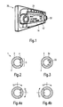
- FIG. 1 A typical application of rotary push buttons can be seen in FIG. 1.
- the figure shows a head unit face plate used for navigation systems installed in vehicles.
- Reference number 30 shows a typical graphical user interface used for a navigation system.
- the user can interact with the menu 14 displayed on the display means 12 by choosing several options with the rotary push button 32 and confirming the desired option with the rotary push button 32. Specific locations can be chosen by selecting the street or the town, so as to get a path indication therefore.
- Additional push buttons 31 may be provided to offer other functionalities.
- a rotary push button 1 is illustrated in a top view.
- the rotary push button 1 comprises an inner component 2, an outer ring 3 and a visible marker 4 on the inner component. Further an adjacent ring segment 5 is defined as being the segment of the outer ring nearest to the marker.
- the rotary push button 1 is operated by an user.
- the outer ring 3 is subjected to rotary operations. With regard to the rotary operation of the outer ring 3, the inner component 2 is stationary but can be subjected to push operations. Furthermore, in this embodiment the inner component 2 is circular, however other alternatives may also be implemented by a person skilled in the art.
- the marker 4 is fixed on the inner component 2, so as to provide a constant reference point with respect to the movable outer ring 3.
- a horizontal line 33 which extends in a radial direction of the circular inner component 2 is used as visible marker 4.
- a ring segment is being defined as the part of the ring being adjacent to the marker 4 of the inner component 2. Therefore the marker poses a perceptive and intuitive support for the user to define moving directions of the adjacent ring segment 5 relative to the marker 4, which will be explained in the following.
- the marker itself is clearly visible for the user and is provided on the inner component.
- the marker is painted or printed on the inner component or if it is a small protrusion or indention on the inner component.
- the visible marker 4 on the inner component consists of a horizontal line 33 and two arrows 34 pointing in a general vertical direction.
- a direct visual feedback of the action performed by a user is provided by the arrows, because the arrows clearly indicate which moving direction is achieved by a rotation of the outer ring 3.
- the marker may be positioned in a different location respectively, being in a right position in FIG. 4a and in a left position of the inner component in FIG. 4b.
- Other possible positions, although not shown in the figures may be an upper and lower position of the inner component.
- variable perceptible moving directions can be achieved.
- the perceptible moving direction is defined as the direction in which the adjacent ring segment 5 is moved relative to the marker 4 of the inner component 2, when the outer ring 3 is subjected to rotary operations.
- the perceptible moving direction can be used to coincide with the moving direction of a cursor for a graphical user interface.
- an up-down perceptible moving direction is achieved. Specifically a clockwise rotation leads to a down moving direction perceptible for the user, as the adjacent ring segment 5 moves in a downward direction relative to the rotary fixed marker 4. Accordingly a counterclockwise rotation of the outer ring 3 results in an up moving direction perceptible for the user, as the adjacent ring segment 5 moves in an upward direction relative to the rotary fixed marker 4.
- FIG. 4b shows the rotary push button 1 in one embodiment including the marker 4 in a left position of the inner component 2.
- the outer ring 3 is rotated clockwise, an up moving direction is achieved, because the adjacent ring segment 5 rotates in an upward direction relative to the rotary fixed marker 4. Consequently, a downward direction is achieved by a counterclockwise rotation, as the adjacent ring segment 5 is rotated in an upward direction relative to the rotary fixed marker 4.
- contrary moving directions perceptible for the user can be attained by different positions of the marker.
- positions of the marker cause different perceptible moving directions.
- a upper and lower positioning of the marker 4 yields left-right moving directions, perceptible for the user.
- a user adjustment of the marker position may also be possible.
- a user may be accustomed to a familiar connection between the rotation of an outer ring and the resulting moving direction used for interacting with a graphical user interface.
- the user can change the position of the inner component during an adjustment process, so as to change the position of the marker relative to the outer ring.
- FIG. 5 is an exploded perspective view of the rotary push button 1.
- the rotary push button 1 has a longitudinal axis 6, whereas the inner component 2 is longitudinally movable along the longitudinal axis 6 to define a push operation.
- the outer ring 3 is rotatable about the longitudinal axis 6 to define a rotary operation.
- a sensor element 7 is depicted.
- the sensor element 7 is provided with sensor contacts 8 to detect and quantify the direction and magnitude of rotation of the outer ring 3 by the user.
- the sensor contacts detect the push operation of the inner component 2.
- a control signal 10 is generated, which may be used to control a vehicle function.
- the rotary push button has at least one sensor element to be able to detect and quantify the operations of the rotary push button 1 performed by the user. Other means of detecting and quantifying the operations of the rotary push button 1 are possible.
- a graphical user interface 11 comprising a display means 12, a cursor 13, a menu 14, a scroll up direction 15, a scroll down direction 16, a confirmation action 17 and the rotary push button 1.
- the user interacts with the graphical user interface with suitable input/output means including the rotary push button 1 to perform various functions supported by the graphical user interface, for example operating an audio system or selecting a specific function of the information system of the vehicle.
- the user operates the rotary push button 1 to control the cursor 13 visible on the menu 14 displayed on the display means 12 of the graphical user interface 11.
- the interactions in this embodiment are limited to the scroll up direction 15, scroll down direction 16 and to the confirmation action 17.
- the interactions are displayed on the display means 12 only to give the user a visual feedback of the executed action.
- other alternatives may also be available for those skilled in the art.
- the perceptible moving direction of the outer ring 3 relative to the marker 4 corresponds to the scroll up direction 15 or scroll down direction 16 action on the graphical user interface 11.
- a clockwise rotation of the outer ring 3 results in a downward rotation of the adjacent ring segment 5 coinciding with the scroll down direction in the graphical user interface.
- FIG. 7 a block diagram of a signal processing unit 18 is shown, comprising input means 19, memory 20, processing means 21 and output means 22.
- the signal processing unit 18 can transform the control signal 10 received from the rotary push button into an appropriate output control signal 23 for the graphical user interface 11.
- the button control signal 10 is processed in a first instance by input means 19, thereby for example digitalizing the input.
- the processed information of the actual operation of the rotary push button may be stored temporarily in a memory block 20. Afterward a processor 21 computes an appropriate interaction signal 23 for the graphical user interface 11 and finally outputs the resulting interaction signal 23 via output means 22 to the graphical user interface 11.
Landscapes
- Engineering & Computer Science (AREA)
- General Engineering & Computer Science (AREA)
- Theoretical Computer Science (AREA)
- Human Computer Interaction (AREA)
- Physics & Mathematics (AREA)
- General Physics & Mathematics (AREA)
- Switches With Compound Operations (AREA)
- Measuring Fluid Pressure (AREA)
- Input From Keyboards Or The Like (AREA)
Abstract
Description
- The present invention relates generally to rotary push buttons, which are preferably applied to graphical user interfaces mounted in a vehicle.
- Many rotary push buttons applying different technologies are known, which combine the rotary movement of a ring element and the hitting of a center button preferably positioned inside the ring element. Examples can be found in
US patent Number 6,706,987 and the US Patent Application PublicationUS2004/0,154,910 .
An ample application field can be found in vehicles, where the user interacts with various vehicle functions such as audio/video entertainment systems, air conditioners or information systems. By manually operating the buttons the user is able to adjust, set and actuate the vehicle functions. - Rotary push buttons further comprise sensing elements for detecting and quantifying the amount and direction of a rotary movement of the ring element operated by the user and for detecting the pressing of the center element. These are typically assembled in a housing in cooperation with a mechanism that enables the appropriate movement of the button elements. In many applications, a contact adjacent to the push botton generates a signal corresponding to the on/off position of the center button and the actuator disposed in the center button. A return spring can be used to move the actuator and the button back to the original off position.
The outer ring element is assembled to allow the rotary operation by a user and the sensing elements generate a signal according to the direction and quantity of the rotation. - For a graphical user interface the manual rotation of the outer ring by an operater is used to select an menu element or to move a cursor in a volitional direction. However there are different perceptions of what a clockwise/counterclockwise rotation of the ring corresponds to for the movement of a cursor. For example a clockwise rotation can correspond to an interpreted down-direction for a scrolling function. Whereas the same clockwise rotation can be interpreted contrary as an up-direction for the scrolling function. The user has no possibility to know or infer in advance the direction interpreted by the manufacturer. This can lead to unwanted maloperations.
- Accordingly an object of the present invention is to prevent a maloperation due to the different interpretations by the different manufacturers of a rotary movement of a ring element.
- To achieve the above object the present invention provides a rotary push button, comprising an outer ring, which can be subjected to rotary operations and an inner component, which can be subjected to push operations but which is stationary with respect to rotation of the outer ring. The inner component includes a visible marker. A specific positioning of the visible marker on the inner component allows an unambiguous interpretation of the resulting moving direction. During the rotation of the outer ring the outer ring segment adjacent to the marker is moved in a direction relative to the marker on the stationary inner component. By including a visible marker on the stationary inner component a user can clearly infer the moving direction used for e.g. a scrolling function. Depending on the position of the marker on the inner component a clockwise/counterclockwise rotation clearly defines a moving direction perceptible for the user.
- The advantages of the present invention can be easily derived. The user, when confronted with the task of selecting an element of a menu displayed on a graphical user interface by using a conventional rotary push button does not know in advance in which way a clockwise/counterclockwise rotation of an outer ring coincides with the scroll up/scroll down direction of the graphical user interface.
- This leads to maloperations as the user cannot infer or know in advance the relationship between the rotation of the outer ring and the resulting moving direction of a cursor or pointer of the graphical user interface. The user, possibly being accustomed to a certain relationship contrary to the relationship interpreted by the manufacturer has to adapt to the customized resulting moving directions used for the scroll up/scroll down function. The learning time is further prolonged due to the fact that no features facilitate the inference of the relationship chosen by the manufacturer.
- The present invention is therefore useful in several ways. The user can easily derive the resulting moving direction perceptible for the user by considering the rotation of the outer ring relative to the marker. Depending on the position of the marker a clockwise rotation results in a down or up moving direction which can be easily perceived by the user in advance. Thereby maloperations are significantly reduced or even eliminated. In one advantageous embodiment, the adaptation of the user to an unfamiliar relationship between the rotation of the outer ring and the resulting perceptible moving direction is eased, because before the actual operation of the rotary push button the user may receive a visual feedback of how the rotation is defined by the manufacturer.
- In another embodiment the user is able to adapt the rotary push button to his familiar interpretation of the rotation and resulting moving direction relationship. During an adjustment process the inner component and the marker thereon can be changed so as to alter the marker position relative to the outer ring. Thereby maloperations are reduced or eliminated, because the user is familiar with the resulting interpretation. Logically an adaptation to a new interpretation of the rotation definition can thereby be excluded.
-
- FIG. 1
- is a vehicle audio head unit face plate of a navigation device.
- FIG. 2
- is a top view of the rotary push button.
- FIG. 3
- is another top view of the rotary push button of an advantageous embodiment.
- FIG. 4a and FIG. 4b
- are top views of the rotary push button when it is subjected to rotary operations.
- FIG. 5
- is an exploded perspective view of the rotary push button in accordance with one embodiment of the present invention.
- FIG. 6
- illustrates a graphical user interface.
- FIG. 7
- is a block diagram of a signal processing unit according to one embodiment of the present invention.
- Now, preferred embodiments of the present invention will be described in detail with reference to the annexed drawings.
A typical application of rotary push buttons can be seen in FIG. 1. The figure shows a head unit face plate used for navigation systems installed in vehicles.Reference number 30 shows a typical graphical user interface used for a navigation system. The user can interact with themenu 14 displayed on the display means 12 by choosing several options with therotary push button 32 and confirming the desired option with therotary push button 32. Specific locations can be chosen by selecting the street or the town, so as to get a path indication therefore.Additional push buttons 31 may be provided to offer other functionalities. - In FIG. 2 a
rotary push button 1 is illustrated in a top view. Therotary push button 1 comprises aninner component 2, anouter ring 3 and avisible marker 4 on the inner component. Further anadjacent ring segment 5 is defined as being the segment of the outer ring nearest to the marker. Therotary push button 1 is operated by an user. Theouter ring 3 is subjected to rotary operations. With regard to the rotary operation of theouter ring 3, theinner component 2 is stationary but can be subjected to push operations. Furthermore, in this embodiment theinner component 2 is circular, however other alternatives may also be implemented by a person skilled in the art. Themarker 4 is fixed on theinner component 2, so as to provide a constant reference point with respect to the movableouter ring 3. Here, ahorizontal line 33 which extends in a radial direction of the circularinner component 2 is used asvisible marker 4. A ring segment is being defined as the part of the ring being adjacent to themarker 4 of theinner component 2. Therefore the marker poses a perceptive and intuitive support for the user to define moving directions of theadjacent ring segment 5 relative to themarker 4, which will be explained in the following. - The marker itself is clearly visible for the user and is provided on the inner component. For the idea of the present invention it is of no importance if the marker is painted or printed on the inner component or if it is a small protrusion or indention on the inner component.
- In Fig. 3 the
visible marker 4 on the inner component consists of ahorizontal line 33 and twoarrows 34 pointing in a general vertical direction. A direct visual feedback of the action performed by a user is provided by the arrows, because the arrows clearly indicate which moving direction is achieved by a rotation of theouter ring 3. - As shown in FIG. 4a and 4b, the marker may be positioned in a different location respectively, being in a right position in FIG. 4a and in a left position of the inner component in FIG. 4b. Other possible positions, although not shown in the figures may be an upper and lower position of the inner component.
By positioning the marker in different locations variable perceptible moving directions can be achieved. In this case the perceptible moving direction is defined as the direction in which theadjacent ring segment 5 is moved relative to themarker 4 of theinner component 2, when theouter ring 3 is subjected to rotary operations. The perceptible moving direction can be used to coincide with the moving direction of a cursor for a graphical user interface. - When the
outer ring 3 is rotated and the marker is in a right position, as depicted in FIG. 4a an up-down perceptible moving direction is achieved. Specifically a clockwise rotation leads to a down moving direction perceptible for the user, as theadjacent ring segment 5 moves in a downward direction relative to the rotary fixedmarker 4. Accordingly a counterclockwise rotation of theouter ring 3 results in an up moving direction perceptible for the user, as theadjacent ring segment 5 moves in an upward direction relative to the rotary fixedmarker 4. - A left position of the marker yields contrary perceptible moving directions, as explained in detail below. FIG. 4b shows the
rotary push button 1 in one embodiment including themarker 4 in a left position of theinner component 2. In this case, when theouter ring 3 is rotated clockwise, an up moving direction is achieved, because theadjacent ring segment 5 rotates in an upward direction relative to the rotary fixedmarker 4. Consequently, a downward direction is achieved by a counterclockwise rotation, as theadjacent ring segment 5 is rotated in an upward direction relative to the rotary fixedmarker 4. As shown above, contrary moving directions perceptible for the user can be attained by different positions of the marker. - Other positions of the marker cause different perceptible moving directions. For example a upper and lower positioning of the
marker 4 yields left-right moving directions, perceptible for the user.
Furthermore, a user adjustment of the marker position may also be possible. A user may be accustomed to a familiar connection between the rotation of an outer ring and the resulting moving direction used for interacting with a graphical user interface. In this embodiment, the user can change the position of the inner component during an adjustment process, so as to change the position of the marker relative to the outer ring. - If the user is accustomed to a clockwise rotation leading to a down moving direction, he can choose to adjust the
inner component 2 and themarker 4 thereon to a right position. Correspondingly if the user is accustomed to the contrary familiar relationship between rotation and resulting moving direction he can adjust theinner component 2 and themarker 4 during the adjustment process to the left position, so as to achieve a perceivable up moving direction during a clockwise rotation. - FIG. 5 is an exploded perspective view of the
rotary push button 1. Therotary push button 1 has alongitudinal axis 6, whereas theinner component 2 is longitudinally movable along thelongitudinal axis 6 to define a push operation. Furthermore theouter ring 3 is rotatable about thelongitudinal axis 6 to define a rotary operation. Additionally asensor element 7 is depicted. Thesensor element 7 is provided withsensor contacts 8 to detect and quantify the direction and magnitude of rotation of theouter ring 3 by the user. In addition, the sensor contacts detect the push operation of theinner component 2. Corresponding to the detected and quantified operations of the rotary push button acontrol signal 10 is generated, which may be used to control a vehicle function. In this embodiment, it is communicated to a graphical user interface via a cable or wire 9. The rotary push button has at least one sensor element to be able to detect and quantify the operations of therotary push button 1 performed by the user. Other means of detecting and quantifying the operations of therotary push button 1 are possible. - In FIG. 6 a
graphical user interface 11 is depicted, comprising a display means 12, acursor 13, amenu 14, a scroll updirection 15, a scroll downdirection 16, aconfirmation action 17 and therotary push button 1. The user interacts with the graphical user interface with suitable input/output means including therotary push button 1 to perform various functions supported by the graphical user interface, for example operating an audio system or selecting a specific function of the information system of the vehicle. The user operates therotary push button 1 to control thecursor 13 visible on themenu 14 displayed on the display means 12 of thegraphical user interface 11. The interactions in this embodiment are limited to the scroll updirection 15, scroll downdirection 16 and to theconfirmation action 17. In this advantageous embodiment the interactions are displayed on the display means 12 only to give the user a visual feedback of the executed action. However it is clear that other alternatives may also be available for those skilled in the art. - From the menu one out of a plurality of optional functions can be selected by moving the cursor to the desired position with the outer ring.
- By rotating the outer ring, the perceptible moving direction of the
outer ring 3 relative to themarker 4 corresponds to the scroll updirection 15 or scroll downdirection 16 action on thegraphical user interface 11. Specifically, if the marker is positioned in a right location of the inner component, as depicted in FIG. 6, a clockwise rotation of theouter ring 3 results in a downward rotation of theadjacent ring segment 5 coinciding with the scroll down direction in the graphical user interface. - Accordingly, a counterclockwise rotation of the
outer ring 3 leads to an upward movement of theadjacent ring segment 5 corresponding to the scroll up direction in the graphical user interface. By conducting these two actions a desired element/function of themenu 14 is selected. Theconfirmation signal 17 to confirm the desired function is conducted by the push operation of theinner component 2 of therotary push button 1. In FIG. 7 a block diagram of asignal processing unit 18 is shown, comprising input means 19,memory 20, processing means 21 and output means 22. Thesignal processing unit 18 can transform thecontrol signal 10 received from the rotary push button into an appropriateoutput control signal 23 for thegraphical user interface 11. Thebutton control signal 10 is processed in a first instance by input means 19, thereby for example digitalizing the input. - The processed information of the actual operation of the rotary push button may be stored temporarily in a
memory block 20. Afterward aprocessor 21 computes anappropriate interaction signal 23 for thegraphical user interface 11 and finally outputs the resultinginteraction signal 23 via output means 22 to thegraphical user interface 11.
Claims (15)
- A rotary push button (1), comprising an outer movable ring (3), subjected to rotary operations and an inner component (2) stationary with respect to the rotary operations of the outer movable ring (3), said inner component (2) being subjected to push operations and located within the outer ring (3),
wherein the inner component (2) includes a visible marker (4), so as to indicate to a user a moving direction of the outer movable ring (3) relative to the marker (4). - The rotary push button according to claim 1, wherein the marker (4) consists of a horizontal line, extending in a radial direction of the inner component.
- The rotary push button according to claim 2, wherein the marker (4) further consists of at least one arrow pointing in a general vertical direction.
- The rotary push button according to claim 3, wherein the inner component (2) is circular and wherein the marker (4) consists of two arrows pointing in opposite circumferential directions.
- The rotary push button according to claim 1-4, having a longitudinal axis (6), wherein the outer movable ring (3) is rotatable about the longitudinal axis (6) to define a rotary operation, and the inner component (2) is longitudinally movable along the longitudinal axis (6) to define a push operation.
- The rotary push button according to claims 1-5, wherein the inner component (2) is adjustable by the user during an adjustment process, so as to change the position of the marker (4) relative to the outer ring (3).
- The rotary push button according to claims 1-6, wherein the inner component (2) and/or the outer ring (3) comprise at least one sensor element (7) to sense the direction and/or magnitude of the rotary operation performed by a user.
- The rotary push button according to claim 7 , wherein the sensor element (7) generates a control signal (10) used for controlling a graphical user interface (11).
- The rotary push button according to claim 8, wherein the control signal (10) is used to control a vehicle function.
- The rotary push button according to claim 8, wherein the inner component (2), when subjected to a push operation is adapted to generate a confirmation signal (10) for the graphical user interface (11).
- The rotary push button according to claim 8, wherein the outer movable ring (3), when subjected to a rotary operation is adapted to generate a direction signal (10) for moving a cursor (13) of the graphical user interface (11).
- The rotary push button according to claim 11, wherein the outer movable ring (3), when subjected to a rotary operation is adapted to generate an up-down signal for scrolling through items of a menu (14) displayed on the graphical user interface (11).
- The rotary push button according to one of claims 1-12, wherein the rotary operations performed by a user cause the outer ring segment (5) adjacent to the marker (4) to move in an up-down direction perceptible by the user with respect to the marker.
- The rotary push button according to claim 11 and 13, wherein the marker (4) is located at a position such that the up-down direction perceptible for the user coincides with the moving direction of the cursor (13).
- A head unit for a vehicle comprising:a graphical user interface (11) having a display means (12), anda rotary push button (1) according to claims 1-11.
Priority Applications (3)
| Application Number | Priority Date | Filing Date | Title |
|---|---|---|---|
| EP05021892A EP1772881B1 (en) | 2005-10-07 | 2005-10-07 | Rotary push button with direction marker |
| DE602005011630T DE602005011630D1 (en) | 2005-10-07 | 2005-10-07 | Rotary pressure switch with direction indicator |
| AT05021892T ATE417355T1 (en) | 2005-10-07 | 2005-10-07 | ROTARY PRESSURE SWITCH WITH DIRECTION INDICATOR |
Applications Claiming Priority (1)
| Application Number | Priority Date | Filing Date | Title |
|---|---|---|---|
| EP05021892A EP1772881B1 (en) | 2005-10-07 | 2005-10-07 | Rotary push button with direction marker |
Publications (2)
| Publication Number | Publication Date |
|---|---|
| EP1772881A1 true EP1772881A1 (en) | 2007-04-11 |
| EP1772881B1 EP1772881B1 (en) | 2008-12-10 |
Family
ID=35431971
Family Applications (1)
| Application Number | Title | Priority Date | Filing Date |
|---|---|---|---|
| EP05021892A Expired - Lifetime EP1772881B1 (en) | 2005-10-07 | 2005-10-07 | Rotary push button with direction marker |
Country Status (3)
| Country | Link |
|---|---|
| EP (1) | EP1772881B1 (en) |
| AT (1) | ATE417355T1 (en) |
| DE (1) | DE602005011630D1 (en) |
Cited By (4)
| Publication number | Priority date | Publication date | Assignee | Title |
|---|---|---|---|---|
| WO2009103597A3 (en) * | 2008-02-20 | 2009-11-05 | Edo Lang | Control device for plumbing appliances |
| EP2423769A1 (en) * | 2010-08-25 | 2012-02-29 | Yokogawa Electric Corporation | Method and apparatus to display device information |
| US9149152B2 (en) | 2010-05-21 | 2015-10-06 | Nestec S.A. | Ergonomic dispenser interface |
| JP2016218892A (en) * | 2015-05-25 | 2016-12-22 | アルプス電気株式会社 | Input device |
Citations (5)
| Publication number | Priority date | Publication date | Assignee | Title |
|---|---|---|---|---|
| US20020196239A1 (en) * | 2001-06-26 | 2002-12-26 | Lee Siew Fei | Joy-dial for providing input signals to a device |
| US20030016208A1 (en) * | 2001-06-29 | 2003-01-23 | Bernd Wiesenauer | Operating device for an in-car computing system and in-car computing system |
| US6706987B1 (en) | 2003-05-01 | 2004-03-16 | Cheol-Sang Yoo | Rotary push switch |
| US20040118664A1 (en) * | 2002-12-19 | 2004-06-24 | Lear Corporation | Multifunction switch and method of using same |
| US20040154910A1 (en) | 2003-02-07 | 2004-08-12 | Alps Electric Co., Ltd. | Rotary push switch device |
-
2005
- 2005-10-07 DE DE602005011630T patent/DE602005011630D1/en not_active Expired - Lifetime
- 2005-10-07 AT AT05021892T patent/ATE417355T1/en not_active IP Right Cessation
- 2005-10-07 EP EP05021892A patent/EP1772881B1/en not_active Expired - Lifetime
Patent Citations (5)
| Publication number | Priority date | Publication date | Assignee | Title |
|---|---|---|---|---|
| US20020196239A1 (en) * | 2001-06-26 | 2002-12-26 | Lee Siew Fei | Joy-dial for providing input signals to a device |
| US20030016208A1 (en) * | 2001-06-29 | 2003-01-23 | Bernd Wiesenauer | Operating device for an in-car computing system and in-car computing system |
| US20040118664A1 (en) * | 2002-12-19 | 2004-06-24 | Lear Corporation | Multifunction switch and method of using same |
| US20040154910A1 (en) | 2003-02-07 | 2004-08-12 | Alps Electric Co., Ltd. | Rotary push switch device |
| US6706987B1 (en) | 2003-05-01 | 2004-03-16 | Cheol-Sang Yoo | Rotary push switch |
Cited By (5)
| Publication number | Priority date | Publication date | Assignee | Title |
|---|---|---|---|---|
| WO2009103597A3 (en) * | 2008-02-20 | 2009-11-05 | Edo Lang | Control device for plumbing appliances |
| US9149152B2 (en) | 2010-05-21 | 2015-10-06 | Nestec S.A. | Ergonomic dispenser interface |
| EP2423769A1 (en) * | 2010-08-25 | 2012-02-29 | Yokogawa Electric Corporation | Method and apparatus to display device information |
| US8933887B2 (en) | 2010-08-25 | 2015-01-13 | Yokogawa Electric Corporation | Device information display apparatus and device information display method |
| JP2016218892A (en) * | 2015-05-25 | 2016-12-22 | アルプス電気株式会社 | Input device |
Also Published As
| Publication number | Publication date |
|---|---|
| ATE417355T1 (en) | 2008-12-15 |
| EP1772881B1 (en) | 2008-12-10 |
| DE602005011630D1 (en) | 2009-01-22 |
Similar Documents
| Publication | Publication Date | Title |
|---|---|---|
| US7310084B2 (en) | Multi-way operation switch, input device and input unit | |
| JP3988646B2 (en) | Vehicle control device | |
| US7579559B2 (en) | Control knob having integrated functionality | |
| US6100476A (en) | Operating device with two-dimensional dialogue movement | |
| US8400333B2 (en) | Multi-directional input apparatus | |
| KR20070016096A (en) | Operating members, especially for multimedia systems in vehicles | |
| US10670140B2 (en) | Apparatus for shifting in an automobile | |
| US11175752B1 (en) | Roller mouse operable in two clicking modes | |
| KR101773032B1 (en) | Multifunctional composite input device | |
| JP2011526385A (en) | Input device having touch-sensitive input device and rotary input device | |
| EP1772881B1 (en) | Rotary push button with direction marker | |
| EP3073503B1 (en) | Multifunctional selection operation switch apparatus | |
| JPWO2014049794A1 (en) | Electronics | |
| US7086292B2 (en) | Force-feedback input device | |
| US7499023B2 (en) | Haptic feedback input device | |
| JP6074097B2 (en) | Electronics | |
| JP4996548B2 (en) | Multi-directional operation switch device | |
| EP3659855B1 (en) | Vehicle with vehicle seat and sensing unit | |
| JP2007073506A (en) | Button device for instruction capable of sensing contact | |
| JP2011100333A (en) | Operation device | |
| JP6610452B2 (en) | Vehicle display device | |
| CN110870204B (en) | Operating device for a motor vehicle, method for operating a motor vehicle with the aid of an operating device, control device and motor vehicle | |
| JP4233375B2 (en) | Operating device and electronic apparatus equipped with the same | |
| KR102217652B1 (en) | Apparatus and method for operating contents menu | |
| CN211454560U (en) | Novel regulating switch |
Legal Events
| Date | Code | Title | Description |
|---|---|---|---|
| PUAI | Public reference made under article 153(3) epc to a published international application that has entered the european phase |
Free format text: ORIGINAL CODE: 0009012 |
|
| AK | Designated contracting states |
Kind code of ref document: A1 Designated state(s): AT BE BG CH CY CZ DE DK EE ES FI FR GB GR HU IE IS IT LI LT LU LV MC NL PL PT RO SE SI SK TR |
|
| AX | Request for extension of the european patent |
Extension state: AL BA HR MK YU |
|
| 17P | Request for examination filed |
Effective date: 20071009 |
|
| AKX | Designation fees paid |
Designated state(s): AT BE BG CH CY CZ DE DK EE ES FI FR GB GR HU IE IS IT LI LT LU LV MC NL PL PT RO SE SI SK TR |
|
| GRAP | Despatch of communication of intention to grant a patent |
Free format text: ORIGINAL CODE: EPIDOSNIGR1 |
|
| GRAS | Grant fee paid |
Free format text: ORIGINAL CODE: EPIDOSNIGR3 |
|
| GRAA | (expected) grant |
Free format text: ORIGINAL CODE: 0009210 |
|
| AK | Designated contracting states |
Kind code of ref document: B1 Designated state(s): AT BE BG CH CY CZ DE DK EE ES FI FR GB GR HU IE IS IT LI LT LU LV MC NL PL PT RO SE SI SK TR |
|
| REG | Reference to a national code |
Ref country code: GB Ref legal event code: FG4D |
|
| REG | Reference to a national code |
Ref country code: CH Ref legal event code: EP |
|
| REG | Reference to a national code |
Ref country code: IE Ref legal event code: FG4D |
|
| REF | Corresponds to: |
Ref document number: 602005011630 Country of ref document: DE Date of ref document: 20090122 Kind code of ref document: P |
|
| PG25 | Lapsed in a contracting state [announced via postgrant information from national office to epo] |
Ref country code: LT Free format text: LAPSE BECAUSE OF FAILURE TO SUBMIT A TRANSLATION OF THE DESCRIPTION OR TO PAY THE FEE WITHIN THE PRESCRIBED TIME-LIMIT Effective date: 20081210 |
|
| PG25 | Lapsed in a contracting state [announced via postgrant information from national office to epo] |
Ref country code: NL Free format text: LAPSE BECAUSE OF FAILURE TO SUBMIT A TRANSLATION OF THE DESCRIPTION OR TO PAY THE FEE WITHIN THE PRESCRIBED TIME-LIMIT Effective date: 20081210 Ref country code: SI Free format text: LAPSE BECAUSE OF FAILURE TO SUBMIT A TRANSLATION OF THE DESCRIPTION OR TO PAY THE FEE WITHIN THE PRESCRIBED TIME-LIMIT Effective date: 20081210 Ref country code: FI Free format text: LAPSE BECAUSE OF FAILURE TO SUBMIT A TRANSLATION OF THE DESCRIPTION OR TO PAY THE FEE WITHIN THE PRESCRIBED TIME-LIMIT Effective date: 20081210 Ref country code: LV Free format text: LAPSE BECAUSE OF FAILURE TO SUBMIT A TRANSLATION OF THE DESCRIPTION OR TO PAY THE FEE WITHIN THE PRESCRIBED TIME-LIMIT Effective date: 20081210 Ref country code: PL Free format text: LAPSE BECAUSE OF FAILURE TO SUBMIT A TRANSLATION OF THE DESCRIPTION OR TO PAY THE FEE WITHIN THE PRESCRIBED TIME-LIMIT Effective date: 20081210 |
|
| NLV1 | Nl: lapsed or annulled due to failure to fulfill the requirements of art. 29p and 29m of the patents act | ||
| PG25 | Lapsed in a contracting state [announced via postgrant information from national office to epo] |
Ref country code: ES Free format text: LAPSE BECAUSE OF FAILURE TO SUBMIT A TRANSLATION OF THE DESCRIPTION OR TO PAY THE FEE WITHIN THE PRESCRIBED TIME-LIMIT Effective date: 20090321 Ref country code: RO Free format text: LAPSE BECAUSE OF FAILURE TO SUBMIT A TRANSLATION OF THE DESCRIPTION OR TO PAY THE FEE WITHIN THE PRESCRIBED TIME-LIMIT Effective date: 20081210 Ref country code: EE Free format text: LAPSE BECAUSE OF FAILURE TO SUBMIT A TRANSLATION OF THE DESCRIPTION OR TO PAY THE FEE WITHIN THE PRESCRIBED TIME-LIMIT Effective date: 20081210 Ref country code: BG Free format text: LAPSE BECAUSE OF FAILURE TO SUBMIT A TRANSLATION OF THE DESCRIPTION OR TO PAY THE FEE WITHIN THE PRESCRIBED TIME-LIMIT Effective date: 20090310 Ref country code: BE Free format text: LAPSE BECAUSE OF FAILURE TO SUBMIT A TRANSLATION OF THE DESCRIPTION OR TO PAY THE FEE WITHIN THE PRESCRIBED TIME-LIMIT Effective date: 20081210 |
|
| PG25 | Lapsed in a contracting state [announced via postgrant information from national office to epo] |
Ref country code: AT Free format text: LAPSE BECAUSE OF FAILURE TO SUBMIT A TRANSLATION OF THE DESCRIPTION OR TO PAY THE FEE WITHIN THE PRESCRIBED TIME-LIMIT Effective date: 20081210 Ref country code: SE Free format text: LAPSE BECAUSE OF FAILURE TO SUBMIT A TRANSLATION OF THE DESCRIPTION OR TO PAY THE FEE WITHIN THE PRESCRIBED TIME-LIMIT Effective date: 20090310 Ref country code: PT Free format text: LAPSE BECAUSE OF FAILURE TO SUBMIT A TRANSLATION OF THE DESCRIPTION OR TO PAY THE FEE WITHIN THE PRESCRIBED TIME-LIMIT Effective date: 20090511 Ref country code: IS Free format text: LAPSE BECAUSE OF FAILURE TO SUBMIT A TRANSLATION OF THE DESCRIPTION OR TO PAY THE FEE WITHIN THE PRESCRIBED TIME-LIMIT Effective date: 20090410 Ref country code: CZ Free format text: LAPSE BECAUSE OF FAILURE TO SUBMIT A TRANSLATION OF THE DESCRIPTION OR TO PAY THE FEE WITHIN THE PRESCRIBED TIME-LIMIT Effective date: 20081210 |
|
| PG25 | Lapsed in a contracting state [announced via postgrant information from national office to epo] |
Ref country code: SK Free format text: LAPSE BECAUSE OF FAILURE TO SUBMIT A TRANSLATION OF THE DESCRIPTION OR TO PAY THE FEE WITHIN THE PRESCRIBED TIME-LIMIT Effective date: 20081210 |
|
| PLBE | No opposition filed within time limit |
Free format text: ORIGINAL CODE: 0009261 |
|
| STAA | Information on the status of an ep patent application or granted ep patent |
Free format text: STATUS: NO OPPOSITION FILED WITHIN TIME LIMIT |
|
| PG25 | Lapsed in a contracting state [announced via postgrant information from national office to epo] |
Ref country code: DK Free format text: LAPSE BECAUSE OF FAILURE TO SUBMIT A TRANSLATION OF THE DESCRIPTION OR TO PAY THE FEE WITHIN THE PRESCRIBED TIME-LIMIT Effective date: 20081210 |
|
| 26N | No opposition filed |
Effective date: 20090911 |
|
| PG25 | Lapsed in a contracting state [announced via postgrant information from national office to epo] |
Ref country code: MC Free format text: LAPSE BECAUSE OF NON-PAYMENT OF DUE FEES Effective date: 20091031 |
|
| REG | Reference to a national code |
Ref country code: CH Ref legal event code: PL |
|
| REG | Reference to a national code |
Ref country code: IE Ref legal event code: MM4A |
|
| PG25 | Lapsed in a contracting state [announced via postgrant information from national office to epo] |
Ref country code: GR Free format text: LAPSE BECAUSE OF FAILURE TO SUBMIT A TRANSLATION OF THE DESCRIPTION OR TO PAY THE FEE WITHIN THE PRESCRIBED TIME-LIMIT Effective date: 20090311 Ref country code: CH Free format text: LAPSE BECAUSE OF NON-PAYMENT OF DUE FEES Effective date: 20091031 Ref country code: IE Free format text: LAPSE BECAUSE OF NON-PAYMENT OF DUE FEES Effective date: 20091007 Ref country code: LI Free format text: LAPSE BECAUSE OF NON-PAYMENT OF DUE FEES Effective date: 20091031 |
|
| PG25 | Lapsed in a contracting state [announced via postgrant information from national office to epo] |
Ref country code: IT Free format text: LAPSE BECAUSE OF FAILURE TO SUBMIT A TRANSLATION OF THE DESCRIPTION OR TO PAY THE FEE WITHIN THE PRESCRIBED TIME-LIMIT Effective date: 20081210 |
|
| PG25 | Lapsed in a contracting state [announced via postgrant information from national office to epo] |
Ref country code: LU Free format text: LAPSE BECAUSE OF NON-PAYMENT OF DUE FEES Effective date: 20091007 |
|
| PG25 | Lapsed in a contracting state [announced via postgrant information from national office to epo] |
Ref country code: HU Free format text: LAPSE BECAUSE OF FAILURE TO SUBMIT A TRANSLATION OF THE DESCRIPTION OR TO PAY THE FEE WITHIN THE PRESCRIBED TIME-LIMIT Effective date: 20090611 |
|
| PG25 | Lapsed in a contracting state [announced via postgrant information from national office to epo] |
Ref country code: TR Free format text: LAPSE BECAUSE OF FAILURE TO SUBMIT A TRANSLATION OF THE DESCRIPTION OR TO PAY THE FEE WITHIN THE PRESCRIBED TIME-LIMIT Effective date: 20081210 |
|
| PG25 | Lapsed in a contracting state [announced via postgrant information from national office to epo] |
Ref country code: CY Free format text: LAPSE BECAUSE OF FAILURE TO SUBMIT A TRANSLATION OF THE DESCRIPTION OR TO PAY THE FEE WITHIN THE PRESCRIBED TIME-LIMIT Effective date: 20081210 |
|
| PGFP | Annual fee paid to national office [announced via postgrant information from national office to epo] |
Ref country code: FR Payment date: 20131017 Year of fee payment: 9 |
|
| REG | Reference to a national code |
Ref country code: FR Ref legal event code: ST Effective date: 20150630 |
|
| PG25 | Lapsed in a contracting state [announced via postgrant information from national office to epo] |
Ref country code: FR Free format text: LAPSE BECAUSE OF NON-PAYMENT OF DUE FEES Effective date: 20141031 |
|
| PGFP | Annual fee paid to national office [announced via postgrant information from national office to epo] |
Ref country code: GB Payment date: 20180925 Year of fee payment: 14 |
|
| GBPC | Gb: european patent ceased through non-payment of renewal fee |
Effective date: 20191007 |
|
| PG25 | Lapsed in a contracting state [announced via postgrant information from national office to epo] |
Ref country code: GB Free format text: LAPSE BECAUSE OF NON-PAYMENT OF DUE FEES Effective date: 20191007 |
|
| REG | Reference to a national code |
Ref country code: DE Ref legal event code: R082 Ref document number: 602005011630 Country of ref document: DE Representative=s name: MAUCHER JENKINS PATENTANWAELTE & RECHTSANWAELT, DE |
|
| P01 | Opt-out of the competence of the unified patent court (upc) registered |
Effective date: 20230526 |
|
| PGFP | Annual fee paid to national office [announced via postgrant information from national office to epo] |
Ref country code: DE Payment date: 20230920 Year of fee payment: 19 |
|
| REG | Reference to a national code |
Ref country code: DE Ref legal event code: R119 Ref document number: 602005011630 Country of ref document: DE |
|
| PG25 | Lapsed in a contracting state [announced via postgrant information from national office to epo] |
Ref country code: DE Free format text: LAPSE BECAUSE OF NON-PAYMENT OF DUE FEES Effective date: 20250501 |