EP1772283B1 - Apparatus for dividing a bundle of sheet material into a number of smaller bundles of sheet material - Google Patents
Apparatus for dividing a bundle of sheet material into a number of smaller bundles of sheet material Download PDFInfo
- Publication number
- EP1772283B1 EP1772283B1 EP06020854A EP06020854A EP1772283B1 EP 1772283 B1 EP1772283 B1 EP 1772283B1 EP 06020854 A EP06020854 A EP 06020854A EP 06020854 A EP06020854 A EP 06020854A EP 1772283 B1 EP1772283 B1 EP 1772283B1
- Authority
- EP
- European Patent Office
- Prior art keywords
- sheet material
- bundle
- platform
- sliding member
- axis
- Prior art date
- Legal status (The legal status is an assumption and is not a legal conclusion. Google has not performed a legal analysis and makes no representation as to the accuracy of the status listed.)
- Active
Links
Images



Classifications
-
- B—PERFORMING OPERATIONS; TRANSPORTING
- B65—CONVEYING; PACKING; STORING; HANDLING THIN OR FILAMENTARY MATERIAL
- B65H—HANDLING THIN OR FILAMENTARY MATERIAL, e.g. SHEETS, WEBS, CABLES
- B65H1/00—Supports or magazines for piles from which articles are to be separated
-
- B—PERFORMING OPERATIONS; TRANSPORTING
- B65—CONVEYING; PACKING; STORING; HANDLING THIN OR FILAMENTARY MATERIAL
- B65H—HANDLING THIN OR FILAMENTARY MATERIAL, e.g. SHEETS, WEBS, CABLES
- B65H33/00—Forming counted batches in delivery pile or stream of articles
- B65H33/06—Forming counted batches in delivery pile or stream of articles by displacing articles to define batches
-
- B—PERFORMING OPERATIONS; TRANSPORTING
- B42—BOOKBINDING; ALBUMS; FILES; SPECIAL PRINTED MATTER
- B42B—PERMANENTLY ATTACHING TOGETHER SHEETS, QUIRES OR SIGNATURES OR PERMANENTLY ATTACHING OBJECTS THERETO
- B42B5/00—Permanently attaching together sheets, quires or signatures otherwise than by stitching
- B42B5/08—Permanently attaching together sheets, quires or signatures otherwise than by stitching by finger, claw or ring-like elements passing through the sheets, quires or signatures
- B42B5/10—Permanently attaching together sheets, quires or signatures otherwise than by stitching by finger, claw or ring-like elements passing through the sheets, quires or signatures the elements being of castellated or comb-like form
- B42B5/103—Devices for assembling the elements with the stack of sheets
-
- B—PERFORMING OPERATIONS; TRANSPORTING
- B65—CONVEYING; PACKING; STORING; HANDLING THIN OR FILAMENTARY MATERIAL
- B65H—HANDLING THIN OR FILAMENTARY MATERIAL, e.g. SHEETS, WEBS, CABLES
- B65H37/00—Article or web delivery apparatus incorporating devices for performing specified auxiliary operations
-
- B—PERFORMING OPERATIONS; TRANSPORTING
- B65—CONVEYING; PACKING; STORING; HANDLING THIN OR FILAMENTARY MATERIAL
- B65H—HANDLING THIN OR FILAMENTARY MATERIAL, e.g. SHEETS, WEBS, CABLES
- B65H2301/00—Handling processes for sheets or webs
- B65H2301/40—Type of handling process
- B65H2301/42—Piling, depiling, handling piles
- B65H2301/421—Forming a pile
- B65H2301/4213—Forming a pile of a limited number of articles, e.g. buffering, forming bundles
-
- B—PERFORMING OPERATIONS; TRANSPORTING
- B65—CONVEYING; PACKING; STORING; HANDLING THIN OR FILAMENTARY MATERIAL
- B65H—HANDLING THIN OR FILAMENTARY MATERIAL, e.g. SHEETS, WEBS, CABLES
- B65H2301/00—Handling processes for sheets or webs
- B65H2301/40—Type of handling process
- B65H2301/42—Piling, depiling, handling piles
- B65H2301/422—Handling piles, sets or stacks of articles
-
- B—PERFORMING OPERATIONS; TRANSPORTING
- B65—CONVEYING; PACKING; STORING; HANDLING THIN OR FILAMENTARY MATERIAL
- B65H—HANDLING THIN OR FILAMENTARY MATERIAL, e.g. SHEETS, WEBS, CABLES
- B65H2301/00—Handling processes for sheets or webs
- B65H2301/40—Type of handling process
- B65H2301/42—Piling, depiling, handling piles
- B65H2301/422—Handling piles, sets or stacks of articles
- B65H2301/4228—Dividing piles
-
- B—PERFORMING OPERATIONS; TRANSPORTING
- B65—CONVEYING; PACKING; STORING; HANDLING THIN OR FILAMENTARY MATERIAL
- B65H—HANDLING THIN OR FILAMENTARY MATERIAL, e.g. SHEETS, WEBS, CABLES
- B65H2301/00—Handling processes for sheets or webs
- B65H2301/50—Auxiliary process performed during handling process
- B65H2301/51—Modifying a characteristic of handled material
- B65H2301/515—Cutting handled material
- B65H2301/5152—Cutting partially, e.g. perforating
-
- B—PERFORMING OPERATIONS; TRANSPORTING
- B65—CONVEYING; PACKING; STORING; HANDLING THIN OR FILAMENTARY MATERIAL
- B65H—HANDLING THIN OR FILAMENTARY MATERIAL, e.g. SHEETS, WEBS, CABLES
- B65H2301/00—Handling processes for sheets or webs
- B65H2301/50—Auxiliary process performed during handling process
- B65H2301/51—Modifying a characteristic of handled material
- B65H2301/515—Cutting handled material
- B65H2301/5154—Cutting handled material from hand-held or table dispenser
-
- B—PERFORMING OPERATIONS; TRANSPORTING
- B65—CONVEYING; PACKING; STORING; HANDLING THIN OR FILAMENTARY MATERIAL
- B65H—HANDLING THIN OR FILAMENTARY MATERIAL, e.g. SHEETS, WEBS, CABLES
- B65H2301/00—Handling processes for sheets or webs
- B65H2301/50—Auxiliary process performed during handling process
- B65H2301/51—Modifying a characteristic of handled material
- B65H2301/515—Cutting handled material
- B65H2301/5159—Cutting handled material shredding
-
- B—PERFORMING OPERATIONS; TRANSPORTING
- B65—CONVEYING; PACKING; STORING; HANDLING THIN OR FILAMENTARY MATERIAL
- B65H—HANDLING THIN OR FILAMENTARY MATERIAL, e.g. SHEETS, WEBS, CABLES
- B65H2402/00—Constructional details of the handling apparatus
- B65H2402/40—Details of frames, housings or mountings of the whole handling apparatus
- B65H2402/41—Portable or hand-held apparatus
Definitions
- the invention relates to an apparatus for dividing a bundle of sheet material into a number of smaller bundles of sheet material.
- the sheet material may be paper, card, plastic or other material or combinations of different kinds of material.
- Such machines are generally provided with openings into which material to be operated upon may be inserted.
- the machines are designed to accommodate bundles of material up to a predetermined maximum total thickness.
- a shredder may be able to shred a bundle of 30 sheets of material of a particular thickness at a time, or 20 sheets of a thicker material.
- the openings into which material is introduced may be sized so as to prevent a user from inserting too thick a bundle of material.
- a user is able to insert a bundle of material of a greater thickness than the maximum thickness that the machine is able to accommodate. If the machine is used in such circumstances, it may become jammed, or may be damaged by the excess material. Even if damage to the machine does not occur, the material may be creased, torn or otherwise damaged by the machine, or by the user in attempting to clear a jam in the machine.
- JP 2003 073 018 describes an apparatus for dividing a bundle of sheet material into a number of smaller bundles of sheet material of a predetermined thickness wherein a taking-out gap is determined by a stopper plate and a gap setting plate to take out the smaller bundle from the bundle of sheet material properly pressed from its back and placed on a loading plate. A movable plate is pressed from underneath the loading plate to take out the smaller bundle.
- an apparatus for dividing a bundle of sheet material into a number of smaller bundles of sheet material of a predetermined thickness comprising
- a support is provided extending above the back wall against which the bundle of sheet material leans whilst the apparatus is in use.
- the platform includes a portion having a surface texture which helps to prevent the bundle of sheet material slipping away from the back wall.
- the apparatus further includes a spindle supported within the recess extending from the front to the back of the platform and on which the sliding member is slidably and pivotably mounted, the spindle coinciding with the axis.
- the sliding member conveniently includes an arm which extends laterally away from the spindle, and on which the finger is located.
- the portion of the sliding member which extends above the platform may be an upstand at the rear thereof.
- the sliding member includes an indentation for receipt of the users finger.
- the axis extends from the front to the back of the platform substantially perpendicularly to the back wall.
- a document binder 10 includes a divider apparatus 12 which comprises a platform 14 extending across the width of the binder 10 with a back wall 16.
- a recess 18 is provided in the platform 14 extending substantially perpendicular to the back wall 16 for the depth of the platform 14.
- a spindle 20 is supported within the recess 18, above the base thereof but below the level of the platform 14 to either side of the recess 18, extending along the length of the recess 18.
- a sliding member 22 is provided on the spindle 20 for movement along the length of the spindle 20.
- the sliding member 22 extends a short distance to one side of the spindle 20, in this case the right, and a greater distance to the other side of the spindle 20, in this case the left, which provides an arm 24 from which protrudes, parallel to the spindle 20 a finger 26.
- the length L of the finger 26 is the same as the thickness of bundle of sheet material which is acceptable for the relevant use, and thus the thickness of bundles into which the large bundle will be divided.
- an upstand 28 Across the width of the sliding member 22 is an upstand 28 which rises above the level of the platform 14 to either side of the recess 18.
- the sliding member 22 has on its upper surface above the spindle an indentation 30 for the operator's finger. If the operator applies pressure to the sliding member 22 just to the right of the spindle 20 the sliding member 22 rotates downwards on the right and upwards on the left. Thus the arm 24 rises and moves the finger 26 up also.
- the apparatus 12 is operated as follows, with particular reference to Figures 4 and 5 .
- a bundle of sheet material 40 to be separated is placed on the platform 14 against the back wall 16.
- a cover 32 of the binder 10 when in its raised position, as shown in the Figures, provides support for the bundle of paper above the back wall 16.
- An area of ridges 34 on the platform 14 helps to prevent the bundle of sheet material 40 sliding across the surface of the platform 14, which may in some embodiments of the binder 10 be slightly curved.
- the user slides the sliding member 22 towards the rear of the recess 18 along the spindle 20 (as indicated by arrow A) until the upstand 28 comes into contact with the bundle of sheet material 40.
- the user then applies pressure to the right of the sliding member 22, in the indentation 30, such that the sliding member 22 rotates on the spindle 20 (as indicated by arrow B) and as the right hand side goes downwards the left hand side goes upwards.
- the arm 24 rises and the finger 26 rises under the most forward sheets of the bundle of sheet material 40.
- part 40 a of the bundle of sheet material 40 is lifted up by the finger 26 and can readily be removed from the large bundle 40 by the user to form a smaller bundle 40 a for operating on by the binder 10.
- the user then repeats the operation, moving the sliding member 22 forwards until the upstand 28 abuts the large bundle of sheet material 40, and again pivoting the sliding member 22 to remove another smaller bundle of sheets 40b, until such time as the whole large bundle 40 has been removed in smaller bundles.
- the apparatus 10 has the advantage that it divides the large bundle of sheet material 40 into smaller bundles of the correct thickness independent of the thickness of each sheet, and without the user having to count the sheets. The result is therefore both more reliable than counting and also much quicker.
- the apparatus is suitable for incorporation into other machinery which needs to operate on a bundle of sheet material of predetermined thickness, such as shredders and punches.
Landscapes
- Engineering & Computer Science (AREA)
- Mechanical Engineering (AREA)
- Textile Engineering (AREA)
- Crushing And Pulverization Processes (AREA)
- Sheets, Magazines, And Separation Thereof (AREA)
- Packaging Of Annular Or Rod-Shaped Articles, Wearing Apparel, Cassettes, Or The Like (AREA)
- Pile Receivers (AREA)
- Control And Other Processes For Unpacking Of Materials (AREA)
Abstract
Description
- The invention relates to an apparatus for dividing a bundle of sheet material into a number of smaller bundles of sheet material. The sheet material may be paper, card, plastic or other material or combinations of different kinds of material.
- Many office machines, such as paper binders, shredders and punches, operate upon piles of paper, card, plastic or other materials, or bundles containing a mixture of such materials. For the sake of convenience, the term "material" will be used herein to encompass paper, card, plastic and other materials, and combinations of these materials.
- Such machines are generally provided with openings into which material to be operated upon may be inserted. In most cases, the machines are designed to accommodate bundles of material up to a predetermined maximum total thickness. For example, a shredder may be able to shred a bundle of 30 sheets of material of a particular thickness at a time, or 20 sheets of a thicker material.
- The openings into which material is introduced may be sized so as to prevent a user from inserting too thick a bundle of material. However, it is often the case that a user is able to insert a bundle of material of a greater thickness than the maximum thickness that the machine is able to accommodate. If the machine is used in such circumstances, it may become jammed, or may be damaged by the excess material. Even if damage to the machine does not occur, the material may be creased, torn or otherwise damaged by the machine, or by the user in attempting to clear a jam in the machine. Whilst this may not be a problem if, for example, the material is to be shredded, it is undesirable when the individual sheets of material are to be bound, for example, as the damage may be detrimental to the appearance of the material, possibly to the extent that the damaged sheets of material must be disposed of and new sheets prepared. This is both wasteful and time-consuming.
- In an attempt to alleviate this problem, many machines are marked with the maximum number of sheets of material that can safely be accommodated. However, such markings assume that all the material used will be of standard thickness, which may not be the case. A further disadvantage of such markings is the time it takes to count out a specified number of sheets of material. Such counting is often unnecessary, as all that is required is to have a bundle of material of a thickness which can be accommodated by the machine.
- There are a number of apparatuses available in the prior art for assessing the size of a bundle of sheet material (e.g. ep
0855221 ,US5,061,139 andDE478198 ) as may be needed when using a binding machine or the like. There is also an example of an apparatus for dividing a stack of sheets into successively equal batches, this being described inUS4,462,736 . This apparatus comprises a base, a vertical rod and a bladed hub rotatably mounted on the rod. Rotation of the bladed hub causes the blades to push sucessive batches of sheets off the top of the stack. -
JP 2003 073 018 - It is an object of the present invention to provide a method and apparatus for dividing a document up into a number of suitably sized parts such that this is easily and reliably undertaken by the user of the binder.
- According to the present invention there is provided an apparatus for dividing a bundle of sheet material into a number of smaller bundles of sheet material of a predetermined thickness comprising
- a platform having a front and a back on which in use the bundle of sheet material to be divided is placed on one of its edges;
- a back wall adjacent the back of the platform against which in use the bundle of sheet material is placed; characterised in that it further comprises:
- a recess in the platform extending from the front to the back of the platform;
- a sliding member moveable from the front to the back of the recess along an axis and pivotable from side to side about the axis and having a portion which extends above the platform;
- a finger protruding rearwardly from the sliding member offset from the axis and having a length equal to the predetermined thickness of the smaller bundles of sheet material, and
- is constructed such that to divide a smaller bundle of sheet material from the bundle of sheet material the sliding member is slid backwards along the axis until the portion of the sliding member which extends above the platform abuts the bundle of sheet material, the sliding member is then pivoted about the axis to lift the finger under a part of the bundle of sheet material such that a smaller bundle of sheet material is lifted upwards and partially separated from the bundle of sheet material such that a user can then readily lift that bundle of sheet material away from the remaining sheet material.
- Preferably a support is provided extending above the back wall against which the bundle of sheet material leans whilst the apparatus is in use.
- Conveniently the platform includes a portion having a surface texture which helps to prevent the bundle of sheet material slipping away from the back wall.
- Preferably the apparatus further includes a spindle supported within the recess extending from the front to the back of the platform and on which the sliding member is slidably and pivotably mounted, the spindle coinciding with the axis.
- The sliding member conveniently includes an arm which extends laterally away from the spindle, and on which the finger is located.
- The portion of the sliding member which extends above the platform may be an upstand at the rear thereof.
- Conveniently the sliding member includes an indentation for receipt of the users finger.
- Preferably the axis extends from the front to the back of the platform substantially perpendicularly to the back wall.
- An embodiment of an apparatus according to the invention, and the method of its use, will now be described, by way of example only, with reference to the accompanying drawings, in which:
-
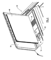
Figure 1 is a perspective view of a document binder incorporating an apparatus according to the invention, with some parts removed for simplicity; -
Figure 2 is a closer perspective view of the apparatus according to the invention incorporated in the binder; -
Figure 3 is a closer plan view of the apparatus according to the invention; and -
Figures 4 and5 are perspective views similar toFigure 2 but with a bundle of sheet material in place and showing the operation of the apparatus according to the invention. - Referring to the Figures, a
document binder 10 includes adivider apparatus 12 which comprises aplatform 14 extending across the width of thebinder 10 with aback wall 16. Arecess 18 is provided in theplatform 14 extending substantially perpendicular to theback wall 16 for the depth of theplatform 14. Aspindle 20 is supported within therecess 18, above the base thereof but below the level of theplatform 14 to either side of therecess 18, extending along the length of therecess 18. A slidingmember 22 is provided on thespindle 20 for movement along the length of thespindle 20. - The sliding
member 22 extends a short distance to one side of thespindle 20, in this case the right, and a greater distance to the other side of thespindle 20, in this case the left, which provides anarm 24 from which protrudes, parallel to the spindle 20 afinger 26. The length L of thefinger 26 is the same as the thickness of bundle of sheet material which is acceptable for the relevant use, and thus the thickness of bundles into which the large bundle will be divided. Across the width of thesliding member 22 is anupstand 28 which rises above the level of theplatform 14 to either side of therecess 18. - The sliding
member 22 has on its upper surface above the spindle anindentation 30 for the operator's finger. If the operator applies pressure to the slidingmember 22 just to the right of thespindle 20 the slidingmember 22 rotates downwards on the right and upwards on the left. Thus thearm 24 rises and moves thefinger 26 up also. - The
apparatus 12 is operated as follows, with particular reference toFigures 4 and5 . A bundle ofsheet material 40 to be separated is placed on theplatform 14 against theback wall 16. Acover 32 of thebinder 10 when in its raised position, as shown in the Figures, provides support for the bundle of paper above theback wall 16. An area ofridges 34 on theplatform 14 helps to prevent the bundle ofsheet material 40 sliding across the surface of theplatform 14, which may in some embodiments of thebinder 10 be slightly curved. - To divide the bundle of
sheet material 40 into smaller bundles the user then slides the slidingmember 22 towards the rear of therecess 18 along the spindle 20 (as indicated by arrow A) until theupstand 28 comes into contact with the bundle ofsheet material 40. The user then applies pressure to the right of the slidingmember 22, in theindentation 30, such that the slidingmember 22 rotates on the spindle 20 (as indicated by arrow B) and as the right hand side goes downwards the left hand side goes upwards. Thus thearm 24 rises and thefinger 26 rises under the most forward sheets of the bundle ofsheet material 40. Thuspart 40a of the bundle ofsheet material 40 is lifted up by thefinger 26 and can readily be removed from thelarge bundle 40 by the user to form asmaller bundle 40a for operating on by thebinder 10. The user then repeats the operation, moving the slidingmember 22 forwards until theupstand 28 abuts the large bundle ofsheet material 40, and again pivoting the slidingmember 22 to remove another smaller bundle of sheets 40b, until such time as the wholelarge bundle 40 has been removed in smaller bundles. - The
apparatus 10 has the advantage that it divides the large bundle ofsheet material 40 into smaller bundles of the correct thickness independent of the thickness of each sheet, and without the user having to count the sheets. The result is therefore both more reliable than counting and also much quicker. - The apparatus is suitable for incorporation into other machinery which needs to operate on a bundle of sheet material of predetermined thickness, such as shredders and punches.
Claims (8)
- An apparatus (12) for dividing a bundle of sheet material (40) into a number of smaller bundles of sheet material (40a) of a predetermined thickness comprising
a platform (14) having a front and a back on which, in use, the bundle of sheet material (40) to be divided is placed on one of its edges;
a back wall (16) adjacent the back of the platform (14) against which, in use, the bundle of sheet material (40) is placed; the apparatus being characterised in that it further comprises:a recess (18) in the platform (14) extending from the front to the back of the platform (14);a sliding member (22) moveable from the front to the back of the recess (18) along an axis (20) and pivotable from side to side about the axis and having a portion (28) which extends above the platform (14);a finger (26) protruding rearwardly from the sliding member (22) offset from the axis (20) and having a length (6) equal to the predetermined thickness of the smaller bundles of sheet material (40a), andis constructed such that to divide a smaller bundle of sheet material (40a) from the bundle of sheet (40) material the sliding member (22) is slid backwards along the axis until the portion (28) of the sliding member (22) which extends above the platform (14) abuts the bundle of sheet material (40), the sliding member (22) is then pivoted about the axis to lift the finger (26) under a part of the bundle of sheet material (40a) such that a smaller bundle of sheet material (40a) is lifted upwards and partially separated from the bundle of sheet material (40) such that a user can then readily lift that bundle of sheet material (40a) away from the remaining sheet material (40). - An apparatus (12) according to claim 1 characterised in that a support (32) is provided extending above the back wall (16) against which the bundle of sheet material leans whilst the apparatus (12) is in use.
- An apparatus (12) according to claim 1 or 2 characterised in that the platform (14) includes a portion (34) having a surface texture which helps to prevent the bundle of sheet material slipping away from the back wall (16).
- An apparatus (12) according to any one of the preceding claims characterised in that it further includes a spindle (20) supported within the recess (18) extending from the front to the back of the platform (14) and on which the sliding member (22) is slidably and pivotably mounted, the spindle coinciding with the axis.
- An apparatus (12) according to claim 4 characterised in that the sliding member (22) includes an arm (24) which extends laterally away from the spindle (20), and on which the finger (26) is located.
- An apparatus (12) according to any one of the preceding claims characterised in that the portion of the sliding member (22) which extends above the platform is an upstand (28) at the rear thereof.
- An apparatus (12) according to any one of the preceding claims characterised in that the sliding member (22) includes an indentation (30) for receipt of a user's finger.
- An apparatus (12) according to any one of the preceding claims characterised in that the axis extends from the front to the back of the platform (14) substantially perpendicularly to the back wall (16).
Applications Claiming Priority (1)
| Application Number | Priority Date | Filing Date | Title |
|---|---|---|---|
| GB0520104A GB2430929A (en) | 2005-10-04 | 2005-10-04 | Apparatus for dividing a bundle of sheet material from a larger bundle |
Publications (2)
| Publication Number | Publication Date |
|---|---|
| EP1772283A1 EP1772283A1 (en) | 2007-04-11 |
| EP1772283B1 true EP1772283B1 (en) | 2008-11-26 |
Family
ID=35395190
Family Applications (1)
| Application Number | Title | Priority Date | Filing Date |
|---|---|---|---|
| EP06020854A Active EP1772283B1 (en) | 2005-10-04 | 2006-10-04 | Apparatus for dividing a bundle of sheet material into a number of smaller bundles of sheet material |
Country Status (5)
| Country | Link |
|---|---|
| US (1) | US7503557B2 (en) |
| EP (1) | EP1772283B1 (en) |
| AT (1) | ATE415287T1 (en) |
| DE (1) | DE602006003834D1 (en) |
| GB (1) | GB2430929A (en) |
Families Citing this family (3)
| Publication number | Priority date | Publication date | Assignee | Title |
|---|---|---|---|---|
| AU2011208374B2 (en) * | 2010-01-19 | 2016-09-08 | Polypid Ltd. | Sustained-release nucleic acid matrix compositions |
| USD686656S1 (en) | 2011-04-13 | 2013-07-23 | Acco Uk Limited | Shredder |
| USD686655S1 (en) | 2011-04-13 | 2013-07-23 | Acco Uk Limited | Shredder |
Citations (1)
| Publication number | Priority date | Publication date | Assignee | Title |
|---|---|---|---|---|
| JP2003073018A (en) * | 2001-09-06 | 2003-03-12 | Futaba Koki Kk | Device for simultaneously taking out plural sheet pieces |
Family Cites Families (7)
| Publication number | Priority date | Publication date | Assignee | Title |
|---|---|---|---|---|
| DE478198C (en) | 1929-06-19 | Karl Koehler | Paper layer lifters | |
| US2854150A (en) * | 1957-05-01 | 1958-09-30 | West Virginia Pulp & Paper Co | Means for removing a lift of sheet material from a stack of such material |
| US3996667A (en) * | 1975-08-11 | 1976-12-14 | Barnard George M | Paper sheet counter and separator |
| US4462736A (en) * | 1982-11-29 | 1984-07-31 | Jenkins Carrell L | Paper batch selector |
| JPS6270143A (en) * | 1985-09-20 | 1987-03-31 | Isamu Miura | Transfer plate for paper aligning device |
| US4986713A (en) * | 1989-06-20 | 1991-01-22 | Xerox Corporation | Apparatus for applying hard and soft covers to bound or unbound documents |
| EP0855221B1 (en) | 1997-01-23 | 2002-10-09 | Esselte N.V. | Device for measuring the thickness of a plural sheet comprising document stack |
-
2005
- 2005-10-04 GB GB0520104A patent/GB2430929A/en not_active Withdrawn
-
2006
- 2006-10-03 US US11/538,300 patent/US7503557B2/en active Active
- 2006-10-04 DE DE602006003834T patent/DE602006003834D1/en active Active
- 2006-10-04 AT AT06020854T patent/ATE415287T1/en not_active IP Right Cessation
- 2006-10-04 EP EP06020854A patent/EP1772283B1/en active Active
Patent Citations (1)
| Publication number | Priority date | Publication date | Assignee | Title |
|---|---|---|---|---|
| JP2003073018A (en) * | 2001-09-06 | 2003-03-12 | Futaba Koki Kk | Device for simultaneously taking out plural sheet pieces |
Also Published As
| Publication number | Publication date |
|---|---|
| US20070104565A1 (en) | 2007-05-10 |
| ATE415287T1 (en) | 2008-12-15 |
| US7503557B2 (en) | 2009-03-17 |
| GB0520104D0 (en) | 2005-11-09 |
| GB2430929A (en) | 2007-04-11 |
| DE602006003834D1 (en) | 2009-01-08 |
| EP1772283A1 (en) | 2007-04-11 |
Similar Documents
| Publication | Publication Date | Title |
|---|---|---|
| US5026034A (en) | Document output apparatus having anti-dishevelment device | |
| EP0611719B1 (en) | Paper ejection device for a stencil printing device | |
| JP5031014B2 (en) | Paper post-processing apparatus, paper post-processing method, and image forming apparatus | |
| US5695182A (en) | Corner separator paper feed method and cassette which prevents paper jams during manual feeding | |
| US4219192A (en) | Sheet loading and storing assembly | |
| JP3372066B2 (en) | Paper cassette | |
| US11498079B2 (en) | One hundred sheet dual throat auto-feed paper shredder | |
| GB2206104A (en) | Paper feeding system of shredder | |
| EP0918028B1 (en) | A sheet feeding apparatus | |
| US8651404B2 (en) | Shredder with clip removing structure | |
| US7503557B2 (en) | Apparatus for dividing a bundle of sheet material into a number of smaller bundles of sheet material | |
| JPS6338317B2 (en) | ||
| JP4513442B2 (en) | Stapler staple leg cutting waste disposal equipment | |
| JP4613602B2 (en) | Staple cartridge and staple leg cutting waste processing apparatus in stapler | |
| DE69119044T2 (en) | Envelope feeder | |
| US6264594B1 (en) | Device for handling documents | |
| US7491028B2 (en) | Automatic paper ejector and stacker for punch machine | |
| JP3919561B2 (en) | Sheet processing apparatus and image forming apparatus having the same | |
| GB2429945A (en) | Combined stapler and hole punch with mode selector | |
| KR20040107832A (en) | Paper cassette for printing apparatus | |
| EP1741562B1 (en) | Improvements relating to comb binders | |
| JPH08192392A (en) | Method and cutter for cutting soft long material | |
| JP2012041179A (en) | Recording material processing device | |
| KR20030056689A (en) | Crusher of Paper have tray | |
| CN1828438A (en) | Image forming apparatus |
Legal Events
| Date | Code | Title | Description |
|---|---|---|---|
| PUAI | Public reference made under article 153(3) epc to a published international application that has entered the european phase |
Free format text: ORIGINAL CODE: 0009012 |
|
| AK | Designated contracting states |
Kind code of ref document: A1 Designated state(s): AT BE BG CH CY CZ DE DK EE ES FI FR GB GR HU IE IS IT LI LT LU LV MC NL PL PT RO SE SI SK TR |
|
| AX | Request for extension of the european patent |
Extension state: AL BA HR MK YU |
|
| 17P | Request for examination filed |
Effective date: 20071009 |
|
| 17Q | First examination report despatched |
Effective date: 20071107 |
|
| AKX | Designation fees paid |
Designated state(s): AT BE BG CH CY CZ DE DK EE ES FI FR GB GR HU IE IS IT LI LT LU LV MC NL PL PT RO SE SI SK TR |
|
| GRAP | Despatch of communication of intention to grant a patent |
Free format text: ORIGINAL CODE: EPIDOSNIGR1 |
|
| GRAS | Grant fee paid |
Free format text: ORIGINAL CODE: EPIDOSNIGR3 |
|
| GRAA | (expected) grant |
Free format text: ORIGINAL CODE: 0009210 |
|
| AK | Designated contracting states |
Kind code of ref document: B1 Designated state(s): AT BE BG CH CY CZ DE DK EE ES FI FR GB GR HU IE IS IT LI LT LU LV MC NL PL PT RO SE SI SK TR |
|
| REG | Reference to a national code |
Ref country code: GB Ref legal event code: FG4D |
|
| REG | Reference to a national code |
Ref country code: CH Ref legal event code: EP |
|
| REG | Reference to a national code |
Ref country code: IE Ref legal event code: FG4D |
|
| REF | Corresponds to: |
Ref document number: 602006003834 Country of ref document: DE Date of ref document: 20090108 Kind code of ref document: P |
|
| PG25 | Lapsed in a contracting state [announced via postgrant information from national office to epo] |
Ref country code: ES Free format text: LAPSE BECAUSE OF FAILURE TO SUBMIT A TRANSLATION OF THE DESCRIPTION OR TO PAY THE FEE WITHIN THE PRESCRIBED TIME-LIMIT Effective date: 20090308 Ref country code: AT Free format text: LAPSE BECAUSE OF FAILURE TO SUBMIT A TRANSLATION OF THE DESCRIPTION OR TO PAY THE FEE WITHIN THE PRESCRIBED TIME-LIMIT Effective date: 20081126 Ref country code: LT Free format text: LAPSE BECAUSE OF FAILURE TO SUBMIT A TRANSLATION OF THE DESCRIPTION OR TO PAY THE FEE WITHIN THE PRESCRIBED TIME-LIMIT Effective date: 20081126 |
|
| NLV1 | Nl: lapsed or annulled due to failure to fulfill the requirements of art. 29p and 29m of the patents act | ||
| PG25 | Lapsed in a contracting state [announced via postgrant information from national office to epo] |
Ref country code: FI Free format text: LAPSE BECAUSE OF FAILURE TO SUBMIT A TRANSLATION OF THE DESCRIPTION OR TO PAY THE FEE WITHIN THE PRESCRIBED TIME-LIMIT Effective date: 20081126 Ref country code: SI Free format text: LAPSE BECAUSE OF FAILURE TO SUBMIT A TRANSLATION OF THE DESCRIPTION OR TO PAY THE FEE WITHIN THE PRESCRIBED TIME-LIMIT Effective date: 20081126 Ref country code: PL Free format text: LAPSE BECAUSE OF FAILURE TO SUBMIT A TRANSLATION OF THE DESCRIPTION OR TO PAY THE FEE WITHIN THE PRESCRIBED TIME-LIMIT Effective date: 20081126 Ref country code: NL Free format text: LAPSE BECAUSE OF FAILURE TO SUBMIT A TRANSLATION OF THE DESCRIPTION OR TO PAY THE FEE WITHIN THE PRESCRIBED TIME-LIMIT Effective date: 20081126 Ref country code: IS Free format text: LAPSE BECAUSE OF FAILURE TO SUBMIT A TRANSLATION OF THE DESCRIPTION OR TO PAY THE FEE WITHIN THE PRESCRIBED TIME-LIMIT Effective date: 20090326 Ref country code: LV Free format text: LAPSE BECAUSE OF FAILURE TO SUBMIT A TRANSLATION OF THE DESCRIPTION OR TO PAY THE FEE WITHIN THE PRESCRIBED TIME-LIMIT Effective date: 20081126 |
|
| PG25 | Lapsed in a contracting state [announced via postgrant information from national office to epo] |
Ref country code: RO Free format text: LAPSE BECAUSE OF FAILURE TO SUBMIT A TRANSLATION OF THE DESCRIPTION OR TO PAY THE FEE WITHIN THE PRESCRIBED TIME-LIMIT Effective date: 20081126 Ref country code: EE Free format text: LAPSE BECAUSE OF FAILURE TO SUBMIT A TRANSLATION OF THE DESCRIPTION OR TO PAY THE FEE WITHIN THE PRESCRIBED TIME-LIMIT Effective date: 20081126 Ref country code: BE Free format text: LAPSE BECAUSE OF FAILURE TO SUBMIT A TRANSLATION OF THE DESCRIPTION OR TO PAY THE FEE WITHIN THE PRESCRIBED TIME-LIMIT Effective date: 20081126 Ref country code: BG Free format text: LAPSE BECAUSE OF FAILURE TO SUBMIT A TRANSLATION OF THE DESCRIPTION OR TO PAY THE FEE WITHIN THE PRESCRIBED TIME-LIMIT Effective date: 20090226 Ref country code: DK Free format text: LAPSE BECAUSE OF FAILURE TO SUBMIT A TRANSLATION OF THE DESCRIPTION OR TO PAY THE FEE WITHIN THE PRESCRIBED TIME-LIMIT Effective date: 20081126 |
|
| PG25 | Lapsed in a contracting state [announced via postgrant information from national office to epo] |
Ref country code: PT Free format text: LAPSE BECAUSE OF FAILURE TO SUBMIT A TRANSLATION OF THE DESCRIPTION OR TO PAY THE FEE WITHIN THE PRESCRIBED TIME-LIMIT Effective date: 20090427 Ref country code: SE Free format text: LAPSE BECAUSE OF FAILURE TO SUBMIT A TRANSLATION OF THE DESCRIPTION OR TO PAY THE FEE WITHIN THE PRESCRIBED TIME-LIMIT Effective date: 20090226 Ref country code: CZ Free format text: LAPSE BECAUSE OF FAILURE TO SUBMIT A TRANSLATION OF THE DESCRIPTION OR TO PAY THE FEE WITHIN THE PRESCRIBED TIME-LIMIT Effective date: 20081126 |
|
| PG25 | Lapsed in a contracting state [announced via postgrant information from national office to epo] |
Ref country code: SK Free format text: LAPSE BECAUSE OF FAILURE TO SUBMIT A TRANSLATION OF THE DESCRIPTION OR TO PAY THE FEE WITHIN THE PRESCRIBED TIME-LIMIT Effective date: 20081126 |
|
| PLBE | No opposition filed within time limit |
Free format text: ORIGINAL CODE: 0009261 |
|
| STAA | Information on the status of an ep patent application or granted ep patent |
Free format text: STATUS: NO OPPOSITION FILED WITHIN TIME LIMIT |
|
| 26N | No opposition filed |
Effective date: 20090827 |
|
| PG25 | Lapsed in a contracting state [announced via postgrant information from national office to epo] |
Ref country code: MC Free format text: LAPSE BECAUSE OF NON-PAYMENT OF DUE FEES Effective date: 20091031 |
|
| REG | Reference to a national code |
Ref country code: IE Ref legal event code: MM4A |
|
| PG25 | Lapsed in a contracting state [announced via postgrant information from national office to epo] |
Ref country code: IE Free format text: LAPSE BECAUSE OF NON-PAYMENT OF DUE FEES Effective date: 20091004 Ref country code: GR Free format text: LAPSE BECAUSE OF FAILURE TO SUBMIT A TRANSLATION OF THE DESCRIPTION OR TO PAY THE FEE WITHIN THE PRESCRIBED TIME-LIMIT Effective date: 20090227 |
|
| PG25 | Lapsed in a contracting state [announced via postgrant information from national office to epo] |
Ref country code: IT Free format text: LAPSE BECAUSE OF FAILURE TO SUBMIT A TRANSLATION OF THE DESCRIPTION OR TO PAY THE FEE WITHIN THE PRESCRIBED TIME-LIMIT Effective date: 20081126 |
|
| PG25 | Lapsed in a contracting state [announced via postgrant information from national office to epo] |
Ref country code: LU Free format text: LAPSE BECAUSE OF NON-PAYMENT OF DUE FEES Effective date: 20091004 |
|
| REG | Reference to a national code |
Ref country code: CH Ref legal event code: PL |
|
| PG25 | Lapsed in a contracting state [announced via postgrant information from national office to epo] |
Ref country code: HU Free format text: LAPSE BECAUSE OF FAILURE TO SUBMIT A TRANSLATION OF THE DESCRIPTION OR TO PAY THE FEE WITHIN THE PRESCRIBED TIME-LIMIT Effective date: 20090527 |
|
| PG25 | Lapsed in a contracting state [announced via postgrant information from national office to epo] |
Ref country code: LI Free format text: LAPSE BECAUSE OF NON-PAYMENT OF DUE FEES Effective date: 20101031 Ref country code: CH Free format text: LAPSE BECAUSE OF NON-PAYMENT OF DUE FEES Effective date: 20101031 |
|
| PG25 | Lapsed in a contracting state [announced via postgrant information from national office to epo] |
Ref country code: TR Free format text: LAPSE BECAUSE OF FAILURE TO SUBMIT A TRANSLATION OF THE DESCRIPTION OR TO PAY THE FEE WITHIN THE PRESCRIBED TIME-LIMIT Effective date: 20081126 |
|
| PG25 | Lapsed in a contracting state [announced via postgrant information from national office to epo] |
Ref country code: CY Free format text: LAPSE BECAUSE OF FAILURE TO SUBMIT A TRANSLATION OF THE DESCRIPTION OR TO PAY THE FEE WITHIN THE PRESCRIBED TIME-LIMIT Effective date: 20081126 |
|
| PGFP | Annual fee paid to national office [announced via postgrant information from national office to epo] |
Ref country code: DE Payment date: 20131029 Year of fee payment: 8 Ref country code: FR Payment date: 20131017 Year of fee payment: 8 |
|
| REG | Reference to a national code |
Ref country code: DE Ref legal event code: R119 Ref document number: 602006003834 Country of ref document: DE |
|
| PG25 | Lapsed in a contracting state [announced via postgrant information from national office to epo] |
Ref country code: DE Free format text: LAPSE BECAUSE OF NON-PAYMENT OF DUE FEES Effective date: 20150501 |
|
| REG | Reference to a national code |
Ref country code: FR Ref legal event code: ST Effective date: 20150630 |
|
| PG25 | Lapsed in a contracting state [announced via postgrant information from national office to epo] |
Ref country code: FR Free format text: LAPSE BECAUSE OF NON-PAYMENT OF DUE FEES Effective date: 20141031 |
|
| PGFP | Annual fee paid to national office [announced via postgrant information from national office to epo] |
Ref country code: GB Payment date: 20250923 Year of fee payment: 20 |