EP1772192A1 - Biochemical processing apparatus provided with liquid transport mechanism - Google Patents
Biochemical processing apparatus provided with liquid transport mechanism Download PDFInfo
- Publication number
- EP1772192A1 EP1772192A1 EP06121616A EP06121616A EP1772192A1 EP 1772192 A1 EP1772192 A1 EP 1772192A1 EP 06121616 A EP06121616 A EP 06121616A EP 06121616 A EP06121616 A EP 06121616A EP 1772192 A1 EP1772192 A1 EP 1772192A1
- Authority
- EP
- European Patent Office
- Prior art keywords
- pipette
- processing apparatus
- storage space
- sample
- biochemical processing
- Prior art date
- Legal status (The legal status is an assumption and is not a legal conclusion. Google has not performed a legal analysis and makes no representation as to the accuracy of the status listed.)
- Granted
Links
- 238000012545 processing Methods 0.000 title claims abstract description 73
- 239000007788 liquid Substances 0.000 title claims abstract description 16
- 230000007723 transport mechanism Effects 0.000 title 1
- 238000006243 chemical reaction Methods 0.000 claims abstract description 25
- 239000003153 chemical reaction reagent Substances 0.000 claims description 46
- 230000003321 amplification Effects 0.000 claims description 20
- 238000003199 nucleic acid amplification method Methods 0.000 claims description 20
- 108020004707 nucleic acids Proteins 0.000 claims description 15
- 150000007523 nucleic acids Chemical class 0.000 claims description 15
- 102000039446 nucleic acids Human genes 0.000 claims description 15
- 238000012360 testing method Methods 0.000 claims description 12
- 238000009396 hybridization Methods 0.000 claims description 6
- 239000000523 sample Substances 0.000 description 63
- 238000000605 extraction Methods 0.000 description 21
- 238000000018 DNA microarray Methods 0.000 description 15
- 230000000977 initiatory effect Effects 0.000 description 4
- 238000000034 method Methods 0.000 description 4
- 108090000623 proteins and genes Proteins 0.000 description 4
- 239000003298 DNA probe Substances 0.000 description 3
- 238000004458 analytical method Methods 0.000 description 3
- 238000011109 contamination Methods 0.000 description 3
- 238000002156 mixing Methods 0.000 description 3
- 239000000203 mixture Substances 0.000 description 3
- 238000012546 transfer Methods 0.000 description 3
- 108020003215 DNA Probes Proteins 0.000 description 2
- 239000000969 carrier Substances 0.000 description 2
- 238000002372 labelling Methods 0.000 description 2
- 238000002360 preparation method Methods 0.000 description 2
- 238000000746 purification Methods 0.000 description 2
- 238000003756 stirring Methods 0.000 description 2
- 239000000126 substance Substances 0.000 description 2
- 239000000758 substrate Substances 0.000 description 2
- XUIMIQQOPSSXEZ-UHFFFAOYSA-N Silicon Chemical compound [Si] XUIMIQQOPSSXEZ-UHFFFAOYSA-N 0.000 description 1
- 238000001514 detection method Methods 0.000 description 1
- 239000007850 fluorescent dye Substances 0.000 description 1
- 239000011521 glass Substances 0.000 description 1
- 238000009434 installation Methods 0.000 description 1
- 239000011159 matrix material Substances 0.000 description 1
- 238000002493 microarray Methods 0.000 description 1
- 238000012986 modification Methods 0.000 description 1
- 230000004048 modification Effects 0.000 description 1
- 244000052769 pathogen Species 0.000 description 1
- 230000001105 regulatory effect Effects 0.000 description 1
- 229910052710 silicon Inorganic materials 0.000 description 1
- 239000010703 silicon Substances 0.000 description 1
- 238000005406 washing Methods 0.000 description 1
Images



Classifications
-
- G—PHYSICS
- G01—MEASURING; TESTING
- G01N—INVESTIGATING OR ANALYSING MATERIALS BY DETERMINING THEIR CHEMICAL OR PHYSICAL PROPERTIES
- G01N35/00—Automatic analysis not limited to methods or materials provided for in any single one of groups G01N1/00 - G01N33/00; Handling materials therefor
- G01N35/10—Devices for transferring samples or any liquids to, in, or from, the analysis apparatus, e.g. suction devices, injection devices
-
- B—PERFORMING OPERATIONS; TRANSPORTING
- B01—PHYSICAL OR CHEMICAL PROCESSES OR APPARATUS IN GENERAL
- B01L—CHEMICAL OR PHYSICAL LABORATORY APPARATUS FOR GENERAL USE
- B01L9/00—Supporting devices; Holding devices
- B01L9/54—Supports specially adapted for pipettes and burettes
- B01L9/543—Supports specially adapted for pipettes and burettes for disposable pipette tips, e.g. racks or cassettes
-
- G—PHYSICS
- G01—MEASURING; TESTING
- G01N—INVESTIGATING OR ANALYSING MATERIALS BY DETERMINING THEIR CHEMICAL OR PHYSICAL PROPERTIES
- G01N35/00—Automatic analysis not limited to methods or materials provided for in any single one of groups G01N1/00 - G01N33/00; Handling materials therefor
- G01N35/10—Devices for transferring samples or any liquids to, in, or from, the analysis apparatus, e.g. suction devices, injection devices
- G01N2035/1027—General features of the devices
- G01N2035/103—General features of the devices using disposable tips
-
- G—PHYSICS
- G01—MEASURING; TESTING
- G01N—INVESTIGATING OR ANALYSING MATERIALS BY DETERMINING THEIR CHEMICAL OR PHYSICAL PROPERTIES
- G01N35/00—Automatic analysis not limited to methods or materials provided for in any single one of groups G01N1/00 - G01N33/00; Handling materials therefor
- G01N35/10—Devices for transferring samples or any liquids to, in, or from, the analysis apparatus, e.g. suction devices, injection devices
- G01N35/1065—Multiple transfer devices
- G01N2035/1076—Multiple transfer devices plurality or independently movable heads
-
- G—PHYSICS
- G01—MEASURING; TESTING
- G01N—INVESTIGATING OR ANALYSING MATERIALS BY DETERMINING THEIR CHEMICAL OR PHYSICAL PROPERTIES
- G01N35/00—Automatic analysis not limited to methods or materials provided for in any single one of groups G01N1/00 - G01N33/00; Handling materials therefor
- G01N35/02—Automatic analysis not limited to methods or materials provided for in any single one of groups G01N1/00 - G01N33/00; Handling materials therefor using a plurality of sample containers moved by a conveyor system past one or more treatment or analysis stations
- G01N35/028—Automatic analysis not limited to methods or materials provided for in any single one of groups G01N1/00 - G01N33/00; Handling materials therefor using a plurality of sample containers moved by a conveyor system past one or more treatment or analysis stations having reaction cells in the form of microtitration plates
-
- G—PHYSICS
- G01—MEASURING; TESTING
- G01N—INVESTIGATING OR ANALYSING MATERIALS BY DETERMINING THEIR CHEMICAL OR PHYSICAL PROPERTIES
- G01N35/00—Automatic analysis not limited to methods or materials provided for in any single one of groups G01N1/00 - G01N33/00; Handling materials therefor
- G01N35/10—Devices for transferring samples or any liquids to, in, or from, the analysis apparatus, e.g. suction devices, injection devices
- G01N35/1081—Devices for transferring samples or any liquids to, in, or from, the analysis apparatus, e.g. suction devices, injection devices characterised by the means for relatively moving the transfer device and the containers in an horizontal plane
- G01N35/109—Devices for transferring samples or any liquids to, in, or from, the analysis apparatus, e.g. suction devices, injection devices characterised by the means for relatively moving the transfer device and the containers in an horizontal plane with two horizontal degrees of freedom
Definitions
- the present invention relates to a biochemical processing apparatus such as a nucleic acid sample testing apparatus. More specifically, the present invention relates to a biochemical processing apparatus adapted for dispensing solutions containing identical samples more than one time for carrying out an examination including or involving multiple reaction steps.
- DNA chip refers to a plurality of DNA probes disposed and fixed as probe spots in a matrix form on a surface of a substrate such as a slide glass or a silicon substrate.
- a labeling substance can be fixed on the detector through a probe nucleic acid.
- the type of the hybridized nucleic acid can be specified by detecting where on the detector the labeling substance is present.
- DNA microarrays utilizing such a hybridization reaction have been expected to be applied to medical diagnoses for specifying pathogens and gene diagnoses for examining constitutions or the like of patients.
- a pipette is typically employed to handle the liquid.
- the pipette to be used is typically of a type in which a pipette chip is mounted on the tip of a syringe.
- disposable pipette chips have been used in general. More specifically, one pipette chip is used for one kind of liquid and then discarded after use. For reducing the number of pipette chips to be discarded, for example, washing of pipette chips ( Japanese Patent Application Laid-Open No. H05-307043 ) and a device for temporarily placing pipette chips in a pipette-chip housing case ( Japanese Patent Application Laid-Open No. H09-096643 ) have been proposed.
- An object of the present invention is to provide a biochemical processing apparatus, which is capable of reducing the number of pipette chips to be used.
- the biochemical processing apparatus of the present invention includes: a plurality of reaction areas of different types; a pipette for dispensing a liquid; a pipette chip removably attachable onto the pipette; and a pipette chip storage space capable of holding the pipette chip, in which the pipette chip storage space is provided in at least a part of the plurality of reaction areas.
- FIG. 1 is a front view of a biochemical processing apparatus of the present invention.
- FIG. 2 is a top view of a biochemical processing apparatus of the present invention.
- FIG. 3 is a right side view of a biochemical processing apparatus of the present invention.
- FIG. 4 is a cross-sectional view of the biochemical processing apparatus taken along the dashed line 4-4 of FIG. 2.
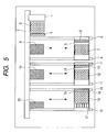
- FIG. 5 is a cross-sectional view of the biochemical processing apparatus taken along the dashed line 5-5 of FIG. 1.
- FIG. 6 is a flowchart for illustrating an example of processing procedures carried out by a biochemical processing apparatus of the present invention.
- FIG. 7 is a flowchart for illustrating another example of processing procedures carried out by a biochemical processing apparatus of the present invention.
- FIG. 8A and FIG. 8B are cross-sectional views each for representing an example of a pipette chip storage portion with which a biochemical processing apparatus of the present invention is provided.
- FIG. 1 is a front view of a biochemical processing apparatus in accordance with an embodiment of the present invention.
- this embodiment will be described exemplifying a nucleic acid sample testing apparatus.
- Both a right door 21 and a left door 22 provided on the front of the nucleic acid sample testing apparatus 23 are opened and a well plate or the like is then placed on an installation site in the apparatus.
- FIG. 2 is a first top view of the nucleic acid sample testing apparatus of the present invention. In the figure, the right and left doors 21 and 22 are being opened.
- FIG. 3 is a right side view of the nucleic acid sample testing apparatus of the present invention.
- FIG. 4 is a cross-sectional view of the nucleic acid sample testing apparatus taken along the dashed line 4-4 of FIG. 2.
- FIG. 5 is a cross-sectional view of the nucleic acid sample testing apparatus taken along the dashed line 5-5 of FIG. 1.
- a pipette 1 for handling a liquid such as a sample or a reagent is connected to a pipette guide 2 for allowing the pipette 1 to move back and forward in a left-to-right direction in FIG. 5 with respect to the surface of the drawing sheet.
- a pipette chip storage space 3 for placing an unused pipette chip thereon and a sample storage space 4 are provided.
- a first step section i.e., first reaction area
- the first step section includes a transport carrier 5, which can move in a direction perpendicular to a direction along which the pipette 1 moves, and a transport guide 6 for guiding the movement of the transport carrier 5.
- a transport carrier 5 which can move in a direction perpendicular to a direction along which the pipette 1 moves, and a transport guide 6 for guiding the movement of the transport carrier 5.
- a reagent container 7 and a pipette chip storage space 8 are arranged on the transport carrier 5.
- a processing section 9 is provided.
- a second step section (i.e., second reaction area) is provided adjacent to the first step section.
- the second step section has the same principal configuration as that of the first step section.
- the second step section includes a transport carrier 10 and a transport guide 11.
- On the transport carrier 10 a reagent container 12 and a pipette chip storage space 13 are arranged.
- a processing section 14 is provided.
- a third step section (i.e., third reaction area) is provided adjacent to the second step section.
- the third step section has the same principal configuration as that of the second step section.
- the third step section includes a transport carrier 15 and a transport guide 16.
- On the transport carrier 15, a DNA microarray 17, a reagent container 18, and a pipette chip storage space 19 are arranged.
- a processing section 20 is provided.
- processing in the first step is initiated after a sample is placed in the sample storage space 4, an unused pipette chip is placed in the pipette chip storage space 3, a pipette chip is placed in the pipette chip storage space 8 of the transport carrier 5, and a reagent is placed in the reagent container 7.
- the conditions for initiating the processing are not limited to those described above.
- the processing may be configured such that it can not be initiated before the pipette chip storage spaces 13 and 19 and the reagent containers 12 and 18 of the transport carriers 10 and 15 are provided with chips and reagents, respectively, while the DNA microarray 17 is arranged in the predetermined DNA microarray storage space.
- the transfer carrier 5 is moved to the processing section 9.
- the pipette 1 is prepared such that an unused pipette chip is attached on the pipette 1 in the pipette chip storage space 3 and then used to suck the sample in the sample storage space 4.
- the pipette 1 moves to the position of the processing section 9, where the pipette 1 discharges the sample into the reagent container 7.
- a predetermined processing is carried out in the processing section 9, thereby completing the processing in the first step.
- the phrase "the processing in the first step” refers to, for example, the processing for extraction and purification, where the first step includes mixing and stirring of the reagent.
- a DNA extracted from the sample is set to a place in the reagent container 7.
- the transfer carrier 10 is moved to the processing section 14.
- the pipette 1 sucks the product of the first-step processing from the reagent container 7 and then discharges the product into the reagent container 12.
- a predetermined processing is carried out in the reagent container 12, thereby completing the processing in the second step.
- the phrase "the processing in the second step” refers to, for example, an amplification processing, which includes steps of mixing and stirring of the reagent, and regulating temperature.
- an amplified DNA is set to a place in the reagent container 12.
- the transfer carrier 15 is moved to the processing section 20.
- the pipette 1 sucks the product of the second-step processing from the reagent container 12 and then discharges the product into the regent container 18.
- the product is mixed and stirred with the reagent, thereby preparing a mixture thereof.
- the mixture is set in a place on a DNA microarray 17, while the processing section 20 regulates temperature, to carry out the processing in the third step.
- the phrase "the processing in the third step” refers to, for example, hybridization.
- the DNA microarray 17 may be designed to reserve the mixture solution on a DNA probe to allow a hybridization reaction.
- the DNA microarray 17 may have a cover over the DNA microarray, or may be designed to have a cartridge structure in which an inlet, a flow channel, a chamber, and an outlet for the liquid are formed.
- a detecting section detects results of the reaction on the DNA microarray 17.
- the detecting section may be arranged within the range of movement of the transport carrier 15, or the DNA microarray 17 may be transferred to the detecting section by means of a transport system or the like for a DNA chip (not sown).
- the present apparatus may be designed such that no detecting section is provided and the reaction results can be thus detected using another detecting device.
- the pipette chip storage spaces 8, 13, and 19 arranged in the respective step sections are provided for temporarily retaining chips when the pipettes are not operated during execution of the respective steps. For instance, when two or more steps are simultaneously processed, a pipette chip may be placed in the pipette chip storage space in one step, while another pipette chip may be attached on a pipette in another step where the processing is being executed.
- the pipette chips used are discarded by a method (not shown) after completion of the processing in all steps.
- the reagent containers 7, 12, and 18 each are also used as a container for mixing or reaction of the reagent.
- the reagent containers can be recovered or discarded after completion of the respective steps by any means (not shown).
- the pipette chip storage spaces 8, 13, and 19 may also be recovered by any means (not shown). If those pipette chip storage spaces 8, 13, and 19 are not disposable, these pipette chip storage spaces 8, 13, and 19 may be designed to prevent a liquid from being attached on any part of them, or may be designed to enable a replacement of any part contaminated with the liquid with a new one, even when a chip is placed on the pipette chip storage spaces 8, 13, and 19.
- all reagents may be previously placed in the respective reagent containers and then mounted on the transport carriers.
- the reagent may be previously stored in the apparatus and then supplied to each of the reagent containers by means of a pipette or the like as required.
- sample storage space may be designed to be used while being placed on the transport carrier.
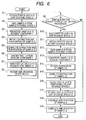
- FIG. 6 is a flowchart for explaining the timing of using the pipette chip storage spaces 8 and 13. In other words, it is a flowchart in a case where the duration of the amplification step is longer than the duration of the extraction step.
- a chip A is attached on a pipette 1 at the pipette chip storage space 3 (Step S1).
- the pipette 1 takes a sample A from the sample storage space 4 (Step S2) and the taken sample A is then placed in the reagent container 7 (Step S3), followed by initiation of extraction of the sample A (Step S4).
- Step S5 After completion of the extraction of the sample A (Step S5), for preparing for amplification, a sample A extract is taken from the reagent container 7 (Step S6) and then placed in the reagent container 12 (Step S7). After completion of the preparation for amplification, the amplification of the sample A extract is initiated (Step S8). Note that, the used reagent container 7 is discarded after completing the step S6.
- Step S9 a next sample B is subjected to determination whether the sample B is waiting for extraction processing or not.
- the chip A is placed in the pipette chip storage space 13 (Step S10).
- a chip B is attached on a pipette 1 at the pipette chip storage space 3 (Step S11) and then the pipette 1 takes the sample B from the sample storage space 4 (Step S12).
- An unused reagent container 7 is placed in place before the processing proceeds to Step S13, and the sample B is then placed in the reagent container 7 (Step S13), followed by initiation of extraction of the sample B (Step S14). After that, the extraction is completed (Step S15).
- Step S16 After completion of the extraction of the sample B, a chip B is placed in the pipette chip storage space 8 (Step S16). Subsequently, the pipette 1 moves to the pipette chip storage space 13 and the chip A is then attached thereon at the pipette chip storage space 13 (Step S17).
- the amplification processing being carried out in the reagent carrier 12 further continues (Step S18). After that, the amplification of the sample A is completed (Step S19).
- FIG. 7 is a flowchart for explaining the timing of using the pipette chip storage spaces 8 and 13. In other words, it is a flowchart in a case where the apparatus is provided with means for determining time at which the steps of amplification and extraction are completed, respectively.
- a chip A is attached on a pipette 1 at the pipette chip storage space 3 (Step S1) and a sample A is then taken from the sample storage space 4 (Step S2). Subsequently, the taken sample A is placed in the reagent container 7 (Step S3) to initiate extraction of the sample A (Step S4). After completion of the extraction of the sample A (Step S5), for preparing for amplification, a sample A extract is taken from the reagent container 7 (Step S6), followed by being placed in the reagent container 12 (Step S7). After completion of the preparation for amplification, the amplification of the sample A extract is initiated (Step S8).
- Step S9 it is determined whether the next sample B is waiting for extraction processing or not.
- the chip A is placed in the pipette chip storage space 13 (Step S10).
- a chip B is attached on the pipette 1 in the pipette chip storage space 3 (Step S11), and the sample B is then taken from the sample storage space 4 (Step S12).
- the taken sample B is placed in the reagent container 7 (Step S13), followed by initiation of extraction of the sample B (Step S14).
- Step S15 it is determined which of the sample B extraction and the sample A amplification requires a pipetting operation. If the sample B extraction requires the pipetting operation, then the extraction keeps on. After completion of the extraction (Step S16), the chip B is placed in the pipette chip storage space 8 (Step S17). After that, a chip A is attached on the pipette 1 in the pipette chip storage space 13 (Step S18) and the sample A amplification keeps on (Step S19), thereby completing the amplification of the sample A (Step S20).
- Step S15 when it is determined that the pipette is required for the sample A amplification, the processing proceeds to Step S21, where the chip B is placed in the pipette chip storage space 8. After that, a chip A is attached on the pipette 1 in the pipette chip storage space 13 (Step S22) and the sample A amplification keeps on (Step S23). After that, the amplification is completed (Step S24). Subsequently, the chip A is placed in the pipette chip storage space 13 (Step S25), and the chip B is then attached on the pipette 1 in the pipette chip storage space 8 (Step S26). Subsequently, the operation of extracting the sample B keeps on (Step S27). After that, the extraction of the sample B is completed (Step S28).
- the determination of a priority level of the pipette 1 is carried out only one time. However, it should be noted that the determination may be carried out two or more times.
- the flow of simultaneously processing of both the first and second steps has been exemplified.
- the simultaneous processing of three steps or the simultaneous processing of the first and third steps may be carried out by the same procedures as described above.
- the chips in use may be optionally placed in the pipette chip storage spaces 8, 13, and 19 in the respective steps, while the pipette 1 is allowed to sequentially shift its position to carry out parallel processing.
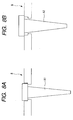
- FIG. 8A and FIG. 8B each represent an example of the pipette chip storage space 8.
- FIG. 8A shows a state in which a chip A1 having a small volume is placed in the pipette chip storage space 8
- FIG. 8B shows a state in which a chip A2 having a large volume is placed in the pipette chip storage space 8.
- the amount of a liquid to be handled in each step may significantly vary, for example, in the range of several microliters to several hundred microliters.
- it is extremely useful that two or more kinds of chips can be placed in one pipette chip storage space.
- pipette chip storage space 8 The specific examples of the pipette chip storage space 8 have been represented in FIG. 8A and FIG. 8B, respectively. It is noted that other pipette chip storage spaces 3, 13, and 19 each represented in FIG. 5 may be designed to have a similar configuration.
- a biochemical processing apparatus includes a plurality of reaction areas of different types, a pipette (1) for dispensing a liquid, a pipette chip removably attachable on the pipette, and pipette chip storage spaces (3, 8, 13, 19) each capable of holding the pipette chip.
- the pipette chip storage spaces are provided in the plurality of reaction areas.
Landscapes
- Chemical & Material Sciences (AREA)
- Health & Medical Sciences (AREA)
- General Health & Medical Sciences (AREA)
- Life Sciences & Earth Sciences (AREA)
- Analytical Chemistry (AREA)
- Biochemistry (AREA)
- Physics & Mathematics (AREA)
- General Physics & Mathematics (AREA)
- Immunology (AREA)
- Pathology (AREA)
- Clinical Laboratory Science (AREA)
- Chemical Kinetics & Catalysis (AREA)
- Apparatus Associated With Microorganisms And Enzymes (AREA)
- Automatic Analysis And Handling Materials Therefor (AREA)
Abstract
Description
- The present invention relates to a biochemical processing apparatus such as a nucleic acid sample testing apparatus. More specifically, the present invention relates to a biochemical processing apparatus adapted for dispensing solutions containing identical samples more than one time for carrying out an examination including or involving multiple reaction steps.
- In recent years, gene analyses using testing pieces, such as microarrays and DNA chips, have been carried out. In those kinds of the gene analyses, a DNA chip is brought into contact with a sample containing a DNA or the like labeled with a fluorescent dye or the like under hybridization conditions. Here, the term "DNA chip" refers to a plurality of DNA probes disposed and fixed as probe spots in a matrix form on a surface of a substrate such as a slide glass or a silicon substrate. When both the detector (i.e., DNA chip) and the sample contain nucleic acids to be hybridized with each other, a labeling substance can be fixed on the detector through a probe nucleic acid. The type of the hybridized nucleic acid can be specified by detecting where on the detector the labeling substance is present.
- DNA microarrays utilizing such a hybridization reaction have been expected to be applied to medical diagnoses for specifying pathogens and gene diagnoses for examining constitutions or the like of patients.
- As with a nucleic acid sample testing apparatus, in any apparatus that handles a liquid such as a sample or a reagent, a pipette is typically employed to handle the liquid. The pipette to be used is typically of a type in which a pipette chip is mounted on the tip of a syringe. In this case, for preventing contamination, disposable pipette chips have been used in general. More specifically, one pipette chip is used for one kind of liquid and then discarded after use. For reducing the number of pipette chips to be discarded, for example, washing of pipette chips (
Japanese Patent Application Laid-Open No. H05-307043 Japanese Patent Application Laid-Open No. H09-096643 - For analyzing a DNA probe, a small amount of a DNA is handled, so attention should be paid on the accuracy of a liquid volume, contamination, and so on. In addition, there is a problem, as described above, in that the use of disposable chips leads to an increase in the number thereof to be discarded. Furthermore, for the gene examination, a plurality of different processing steps, including extraction, amplification, hybridization, and detection of a DNA, should be carried out, while the plurality of steps should be simultaneously carried out in parallel to allow the analysis to be quickly carried out in large amounts.
- An object of the present invention is to provide a biochemical processing apparatus, which is capable of reducing the number of pipette chips to be used.
- The biochemical processing apparatus of the present invention, includes: a plurality of reaction areas of different types; a pipette for dispensing a liquid; a pipette chip removably attachable onto the pipette; and a pipette chip storage space capable of holding the pipette chip, in which the pipette chip storage space is provided in at least a part of the plurality of reaction areas.
- Further features of the present invention will become apparent from the following description of exemplary embodiments with reference to the attached drawings.
- FIG. 1 is a front view of a biochemical processing apparatus of the present invention.
- FIG. 2 is a top view of a biochemical processing apparatus of the present invention.
- FIG. 3 is a right side view of a biochemical processing apparatus of the present invention.
- FIG. 4 is a cross-sectional view of the biochemical processing apparatus taken along the dashed line 4-4 of FIG. 2.
- FIG. 5 is a cross-sectional view of the biochemical processing apparatus taken along the dashed line 5-5 of FIG. 1.
- FIG. 6 is a flowchart for illustrating an example of processing procedures carried out by a biochemical processing apparatus of the present invention.
- FIG. 7 is a flowchart for illustrating another example of processing procedures carried out by a biochemical processing apparatus of the present invention.
- FIG. 8A and FIG. 8B are cross-sectional views each for representing an example of a pipette chip storage portion with which a biochemical processing apparatus of the present invention is provided.
- FIG. 1 is a front view of a biochemical processing apparatus in accordance with an embodiment of the present invention. Here, this embodiment will be described exemplifying a nucleic acid sample testing apparatus. Both a
right door 21 and aleft door 22 provided on the front of the nucleic acidsample testing apparatus 23 are opened and a well plate or the like is then placed on an installation site in the apparatus. FIG. 2 is a first top view of the nucleic acid sample testing apparatus of the present invention. In the figure, the right andleft doors - A
pipette 1 for handling a liquid such as a sample or a reagent is connected to apipette guide 2 for allowing thepipette 1 to move back and forward in a left-to-right direction in FIG. 5 with respect to the surface of the drawing sheet. In addition, within a range of movement of thepipette 1, a pipettechip storage space 3 for placing an unused pipette chip thereon and asample storage space 4 are provided. A first step section (i.e., first reaction area) is provided adjacent to both the pipettechip storage space 3 and thesample storage space 4. The first step section includes atransport carrier 5, which can move in a direction perpendicular to a direction along which thepipette 1 moves, and atransport guide 6 for guiding the movement of thetransport carrier 5. In addition, on thetransport carrier 5, areagent container 7 and a pipettechip storage space 8 are arranged. Furthermore, within a range of movement of thetransport carrier 5, aprocessing section 9 is provided. - A second step section (i.e., second reaction area) is provided adjacent to the first step section. The second step section has the same principal configuration as that of the first step section. The second step section includes a
transport carrier 10 and atransport guide 11. On thetransport carrier 10, areagent container 12 and a pipettechip storage space 13 are arranged. In addition, within a range of movement of thetransport carrier 10, aprocessing section 14 is provided. A third step section (i.e., third reaction area) is provided adjacent to the second step section. The third step section has the same principal configuration as that of the second step section. The third step section includes atransport carrier 15 and atransport guide 16. On thetransport carrier 15, aDNA microarray 17, areagent container 18, and a pipettechip storage space 19 are arranged. Furthermore, within a range of movement of thetransport carrier 10, aprocessing section 20 is provided. - In the above configuration of the apparatus, processing in the first step is initiated after a sample is placed in the
sample storage space 4, an unused pipette chip is placed in the pipettechip storage space 3, a pipette chip is placed in the pipettechip storage space 8 of thetransport carrier 5, and a reagent is placed in thereagent container 7. Note that, the phrase "a reagent is placed in thereagent container 7" refers to both the case of supplying the reagent into thereagent container 7 on thetransport carrier 5 and the case of mounting thereagent container 7, in which the reagent is previously supplied, on thetransport carrier 5. - Properly, the conditions for initiating the processing are not limited to those described above. For instance, the processing may be configured such that it can not be initiated before the pipette
chip storage spaces reagent containers transport carriers DNA microarray 17 is arranged in the predetermined DNA microarray storage space. - First, for carrying out the processing in the first step, the
transfer carrier 5 is moved to theprocessing section 9. Next, thepipette 1 is prepared such that an unused pipette chip is attached on thepipette 1 in the pipettechip storage space 3 and then used to suck the sample in thesample storage space 4. Subsequently, thepipette 1 moves to the position of theprocessing section 9, where thepipette 1 discharges the sample into thereagent container 7. After that, a predetermined processing is carried out in theprocessing section 9, thereby completing the processing in the first step. Here, the phrase "the processing in the first step" refers to, for example, the processing for extraction and purification, where the first step includes mixing and stirring of the reagent. After completion of the processing for extraction and purification, a DNA extracted from the sample is set to a place in thereagent container 7. - Next, for carrying out the processing in the second step, the
transfer carrier 10 is moved to theprocessing section 14. On the other hand, thepipette 1 sucks the product of the first-step processing from thereagent container 7 and then discharges the product into thereagent container 12. Subsequently, a predetermined processing is carried out in thereagent container 12, thereby completing the processing in the second step. Here, the phrase "the processing in the second step" refers to, for example, an amplification processing, which includes steps of mixing and stirring of the reagent, and regulating temperature. After completion of the amplification processing, an amplified DNA is set to a place in thereagent container 12. - Next, for carrying out the processing in the third step, the
transfer carrier 15 is moved to theprocessing section 20. On the other hand, thepipette 1 sucks the product of the second-step processing from thereagent container 12 and then discharges the product into theregent container 18. Subsequently, in thereagent container 18, the product is mixed and stirred with the reagent, thereby preparing a mixture thereof. Then, the mixture is set in a place on aDNA microarray 17, while theprocessing section 20 regulates temperature, to carry out the processing in the third step. Here, the phrase "the processing in the third step" refers to, for example, hybridization. TheDNA microarray 17 may be designed to reserve the mixture solution on a DNA probe to allow a hybridization reaction. For instance, theDNA microarray 17 may have a cover over the DNA microarray, or may be designed to have a cartridge structure in which an inlet, a flow channel, a chamber, and an outlet for the liquid are formed. - After completion of the processing in the third step, a detecting section (not shown) detects results of the reaction on the
DNA microarray 17. The detecting section may be arranged within the range of movement of thetransport carrier 15, or theDNA microarray 17 may be transferred to the detecting section by means of a transport system or the like for a DNA chip (not sown). Alternatively, the present apparatus may be designed such that no detecting section is provided and the reaction results can be thus detected using another detecting device. - The pipette
chip storage spaces - In this embodiment, the pipette chips used are discarded by a method (not shown) after completion of the processing in all steps. In addition, the
reagent containers - The pipette
chip storage spaces chip storage spaces chip storage spaces chip storage spaces - Furthermore, in the above embodiment, all reagents may be previously placed in the respective reagent containers and then mounted on the transport carriers. Alternatively, the reagent may be previously stored in the apparatus and then supplied to each of the reagent containers by means of a pipette or the like as required.
- Furthermore, the sample storage space may be designed to be used while being placed on the transport carrier.
- FIG. 6 is a flowchart for explaining the timing of using the pipette
chip storage spaces - First, a chip A is attached on a
pipette 1 at the pipette chip storage space 3 (Step S1). Thepipette 1 takes a sample A from the sample storage space 4 (Step S2) and the taken sample A is then placed in the reagent container 7 (Step S3), followed by initiation of extraction of the sample A (Step S4). - After completion of the extraction of the sample A (Step S5), for preparing for amplification, a sample A extract is taken from the reagent container 7 (Step S6) and then placed in the reagent container 12 (Step S7). After completion of the preparation for amplification, the amplification of the sample A extract is initiated (Step S8). Note that, the used
reagent container 7 is discarded after completing the step S6. - After that, a next sample B is subjected to determination whether the sample B is waiting for extraction processing or not (Step S9). When it is determined that the sample B is waiting for the extraction processing, the chip A is placed in the pipette chip storage space 13 (Step S10). Subsequently, a chip B is attached on a
pipette 1 at the pipette chip storage space 3 (Step S11) and then thepipette 1 takes the sample B from the sample storage space 4 (Step S12). Anunused reagent container 7 is placed in place before the processing proceeds to Step S13, and the sample B is then placed in the reagent container 7 (Step S13), followed by initiation of extraction of the sample B (Step S14). After that, the extraction is completed (Step S15). - After completion of the extraction of the sample B, a chip B is placed in the pipette chip storage space 8 (Step S16). Subsequently, the
pipette 1 moves to the pipettechip storage space 13 and the chip A is then attached thereon at the pipette chip storage space 13 (Step S17). The amplification processing being carried out in thereagent carrier 12 further continues (Step S18). After that, the amplification of the sample A is completed (Step S19). - FIG. 7 is a flowchart for explaining the timing of using the pipette
chip storage spaces - First, a chip A is attached on a
pipette 1 at the pipette chip storage space 3 (Step S1) and a sample A is then taken from the sample storage space 4 (Step S2). Subsequently, the taken sample A is placed in the reagent container 7 (Step S3) to initiate extraction of the sample A (Step S4). After completion of the extraction of the sample A (Step S5), for preparing for amplification, a sample A extract is taken from the reagent container 7 (Step S6), followed by being placed in the reagent container 12 (Step S7). After completion of the preparation for amplification, the amplification of the sample A extract is initiated (Step S8). - Next, it is determined whether the next sample B is waiting for extraction processing or not (Step S9). When it is determined that the sample B is waiting for the processing, the chip A is placed in the pipette chip storage space 13 (Step S10). Subsequently, a chip B is attached on the
pipette 1 in the pipette chip storage space 3 (Step S11), and the sample B is then taken from the sample storage space 4 (Step S12). After that, the taken sample B is placed in the reagent container 7 (Step S13), followed by initiation of extraction of the sample B (Step S14). - Then, it is determined which of the sample B extraction and the sample A amplification requires a pipetting operation (Step S15). If the sample B extraction requires the pipetting operation, then the extraction keeps on. After completion of the extraction (Step S16), the chip B is placed in the pipette chip storage space 8 (Step S17). After that, a chip A is attached on the
pipette 1 in the pipette chip storage space 13 (Step S18) and the sample A amplification keeps on (Step S19), thereby completing the amplification of the sample A (Step S20). - On the other hand, in Step S15, when it is determined that the pipette is required for the sample A amplification, the processing proceeds to Step S21, where the chip B is placed in the pipette
chip storage space 8. After that, a chip A is attached on thepipette 1 in the pipette chip storage space 13 (Step S22) and the sample A amplification keeps on (Step S23). After that, the amplification is completed (Step S24). Subsequently, the chip A is placed in the pipette chip storage space 13 (Step S25), and the chip B is then attached on thepipette 1 in the pipette chip storage space 8 (Step S26). Subsequently, the operation of extracting the sample B keeps on (Step S27). After that, the extraction of the sample B is completed (Step S28). - As shown in the flowchart shown in FIG. 7, the determination of a priority level of the
pipette 1 is carried out only one time. However, it should be noted that the determination may be carried out two or more times. - As described above, in FIG. 6, the flow of simultaneously processing of both the first and second steps has been exemplified. However, for example, the simultaneous processing of three steps or the simultaneous processing of the first and third steps may be carried out by the same procedures as described above. The chips in use may be optionally placed in the pipette
chip storage spaces pipette 1 is allowed to sequentially shift its position to carry out parallel processing. - By employing the configuration as described above, two or more steps can be simultaneously processed in an efficient manner while permitting reduction in the number of chips to be discarded, without consideration of contamination. Therefore, such the configuration of the nucleic acid sample testing apparatus is extremely useful.
- FIG. 8A and FIG. 8B each represent an example of the pipette
chip storage space 8. FIG. 8A shows a state in which a chip A1 having a small volume is placed in the pipettechip storage space 8, while FIG. 8B shows a state in which a chip A2 having a large volume is placed in the pipettechip storage space 8. In a case where a nucleic acid sample testing apparatus has two or more types of reaction steps, the amount of a liquid to be handled in each step may significantly vary, for example, in the range of several microliters to several hundred microliters. In this case, for keeping accuracy in the amount of a liquid to be dispensed, it is necessary to appropriately use two or more types of pipette chips depending on the amounts of the liquid. Thus, it is extremely useful that two or more kinds of chips can be placed in one pipette chip storage space. - The specific examples of the pipette
chip storage space 8 have been represented in FIG. 8A and FIG. 8B, respectively. It is noted that other pipettechip storage spaces - While the present invention has been described with reference to exemplary embodiments, it is to be understood that the invention is not limited to the disclosed exemplary embodiments. The scope of the following claims is to be accorded the broadest interpretation so as to encompass all such modifications and equivalent structures and functions.
A biochemical processing apparatus includes a plurality of reaction areas of different types, a pipette (1) for dispensing a liquid, a pipette chip removably attachable on the pipette, and pipette chip storage spaces (3, 8, 13, 19) each capable of holding the pipette chip. The pipette chip storage spaces are provided in the plurality of reaction areas.
Claims (10)
- A biochemical processing apparatus, comprising:a plurality of reaction areas of different types;a pipette for dispensing a liquid;a pipette chip removably attachable onto the pipette; anda pipette chip storage space capable of holding the pipette chip, whereinthe pipette chip storage space is provided in at least a part of the plurality of reaction areas.
- A biochemical processing apparatus according to claim 1, wherein the pipette chip storage space is provided for each of the plurality of reaction areas.
- A biochemical processing apparatus according to claim 1, wherein each of the plurality of reaction areas has an area for mounting a reagent container.
- A biochemical processing apparatus according to claim 3, wherein a device for transporting both the pipette chip storage space and the reagent container to any one of the plurality of reaction areas is provided for each of the plurality of reaction areas.
- A biochemical processing apparatus according to claim 4, wherein the plurality of reaction areas allows respective reactions to be simultaneously carried out.
- A biochemical processing apparatus according to claim 1, wherein the pipette chip is disposable.
- A biochemical processing apparatus according to claim 1, wherein the pipette chip storage space is disposable.
- A biochemical processing apparatus according to claim 1, wherein the pipette chip storage space is capable of retaining a plurality of types of the pipette chips.
- A biochemical processing apparatus according to claim 1, wherein the biochemical processing apparatus comprises a nucleic acid sample testing apparatus.
- A biochemical processing apparatus according to claim 1, wherein the plurality of reaction areas include an area for nucleic acid amplification and an area for hybridization.
Applications Claiming Priority (2)
| Application Number | Priority Date | Filing Date | Title |
|---|---|---|---|
| JP2005291395 | 2005-10-04 | ||
| JP2006208662A JP4328787B2 (en) | 2005-10-04 | 2006-07-31 | Nucleic acid sample testing equipment |
Publications (2)
| Publication Number | Publication Date |
|---|---|
| EP1772192A1 true EP1772192A1 (en) | 2007-04-11 |
| EP1772192B1 EP1772192B1 (en) | 2015-01-07 |
Family
ID=37603408
Family Applications (1)
| Application Number | Title | Priority Date | Filing Date |
|---|---|---|---|
| EP06121616.4A Not-in-force EP1772192B1 (en) | 2005-10-04 | 2006-10-02 | Biochemical processing apparatus provided with liquid transport mechanism |
Country Status (3)
| Country | Link |
|---|---|
| US (1) | US20070077172A1 (en) |
| EP (1) | EP1772192B1 (en) |
| JP (1) | JP4328787B2 (en) |
Families Citing this family (6)
| Publication number | Priority date | Publication date | Assignee | Title |
|---|---|---|---|---|
| JP4328788B2 (en) * | 2005-10-04 | 2009-09-09 | キヤノン株式会社 | Nucleic acid sample testing equipment |
| EP2972219B1 (en) | 2013-03-15 | 2022-01-19 | Abbott Laboratories | Automated reagent manager of a diagnostic analyzer system |
| WO2014144870A2 (en) | 2013-03-15 | 2014-09-18 | Abbott Laboratories | Light-blocking system for a diagnostic analyzer |
| US9632103B2 (en) | 2013-03-15 | 2017-04-25 | Abbott Laboraties | Linear track diagnostic analyzer |
| CN112159758A (en) * | 2020-09-22 | 2021-01-01 | 苏州中加康美科技有限公司 | Nucleic acid reagent reaction unit |
| DE102024114661A1 (en) | 2024-05-24 | 2025-11-27 | Bruker Daltonics GmbH & Co. KG | Method for operating a pipetting device and such a device |
Citations (5)
| Publication number | Priority date | Publication date | Assignee | Title |
|---|---|---|---|---|
| EP0185330A2 (en) | 1984-12-18 | 1986-06-25 | Cetus Corporation | Multi-sample liquid handling system |
| US5455008A (en) | 1992-10-16 | 1995-10-03 | Thomas Jefferson University | Apparatus for robotically performing sanger dideoxynucleotide DNA sequencing reactions using controlled pipet |
| US20020028926A1 (en) * | 2000-09-07 | 2002-03-07 | Yoshiyuki Shoji | Nucleic acid purification method and purification apparatus |
| EP1431390A1 (en) | 2001-09-17 | 2004-06-23 | Hitachi, Ltd. | Sample processing device and sample processing method |
| US20050136534A1 (en) | 2003-10-24 | 2005-06-23 | John Austin | Apparatus and method for dispensing fluid, semi-solid and solid samples |
Family Cites Families (5)
| Publication number | Priority date | Publication date | Assignee | Title |
|---|---|---|---|---|
| JP3428426B2 (en) * | 1997-03-26 | 2003-07-22 | 株式会社日立製作所 | Sample analysis system |
| ES2286750T3 (en) * | 1998-05-01 | 2007-12-01 | Gen-Probe Incorporated | DEVICE FOR SHAKING THE LIQUID CONTENT OF A CONTAINER. |
| DE60036746T2 (en) * | 1999-03-25 | 2008-07-24 | Tosoh Corp., Shinnanyo | analyzer |
| US6982063B2 (en) * | 2001-05-25 | 2006-01-03 | Matrix Technologies Corp | Automated pipetting system |
| US6669432B2 (en) * | 2001-08-13 | 2003-12-30 | Matrix Technologies Corp. | Apparatus and method for handling pipetting tip magazines |
-
2006
- 2006-07-31 JP JP2006208662A patent/JP4328787B2/en not_active Expired - Fee Related
- 2006-09-29 US US11/537,140 patent/US20070077172A1/en not_active Abandoned
- 2006-10-02 EP EP06121616.4A patent/EP1772192B1/en not_active Not-in-force
Patent Citations (5)
| Publication number | Priority date | Publication date | Assignee | Title |
|---|---|---|---|---|
| EP0185330A2 (en) | 1984-12-18 | 1986-06-25 | Cetus Corporation | Multi-sample liquid handling system |
| US5455008A (en) | 1992-10-16 | 1995-10-03 | Thomas Jefferson University | Apparatus for robotically performing sanger dideoxynucleotide DNA sequencing reactions using controlled pipet |
| US20020028926A1 (en) * | 2000-09-07 | 2002-03-07 | Yoshiyuki Shoji | Nucleic acid purification method and purification apparatus |
| EP1431390A1 (en) | 2001-09-17 | 2004-06-23 | Hitachi, Ltd. | Sample processing device and sample processing method |
| US20050136534A1 (en) | 2003-10-24 | 2005-06-23 | John Austin | Apparatus and method for dispensing fluid, semi-solid and solid samples |
Also Published As
| Publication number | Publication date |
|---|---|
| EP1772192B1 (en) | 2015-01-07 |
| JP2007127621A (en) | 2007-05-24 |
| US20070077172A1 (en) | 2007-04-05 |
| JP4328787B2 (en) | 2009-09-09 |
Similar Documents
| Publication | Publication Date | Title |
|---|---|---|
| US7879595B2 (en) | Apparatus for performing biochemical processing using container having wells | |
| US8323567B2 (en) | Biochemical treatment device with dispensing unit | |
| EP1340982B1 (en) | Assay work station | |
| CN108220155B (en) | Systems and methods for molecular diagnostics | |
| EP1487580B1 (en) | Hybridization device | |
| EP1612561A1 (en) | Instrument for efficient treatment of analytical devices | |
| US20040071599A1 (en) | Apparatus and method for testing and continuously reading low-volume samples | |
| JP6039395B2 (en) | Preventing contamination | |
| WO2005043154A2 (en) | High density reaction chambers and methods of use | |
| CA2435789A1 (en) | System and cartridge for processing a biological sample | |
| US20100190214A1 (en) | Biochemical treatment apparatus and method comprising liquid handling mechanism | |
| CN101855558A (en) | Sample Handler | |
| US8175810B2 (en) | Sample processing apparatus and sample processing method | |
| EP1772192A1 (en) | Biochemical processing apparatus provided with liquid transport mechanism | |
| JP6184806B2 (en) | Automated method for disposing of chips in an automated processing module and processing system comprising a processing module | |
| JP4328788B2 (en) | Nucleic acid sample testing equipment | |
| US7341865B1 (en) | Liquid delivery devices and methods | |
| EP4465013B1 (en) | Automatic sample preparation system |
Legal Events
| Date | Code | Title | Description |
|---|---|---|---|
| PUAI | Public reference made under article 153(3) epc to a published international application that has entered the european phase |
Free format text: ORIGINAL CODE: 0009012 |
|
| AK | Designated contracting states |
Kind code of ref document: A1 Designated state(s): AT BE BG CH CY CZ DE DK EE ES FI FR GB GR HU IE IS IT LI LT LU LV MC NL PL PT RO SE SI SK TR |
|
| AX | Request for extension of the european patent |
Extension state: AL BA HR MK YU |
|
| 17P | Request for examination filed |
Effective date: 20071011 |
|
| AKX | Designation fees paid |
Designated state(s): DE FR GB |
|
| 17Q | First examination report despatched |
Effective date: 20110304 |
|
| GRAP | Despatch of communication of intention to grant a patent |
Free format text: ORIGINAL CODE: EPIDOSNIGR1 |
|
| INTG | Intention to grant announced |
Effective date: 20140128 |
|
| GRAP | Despatch of communication of intention to grant a patent |
Free format text: ORIGINAL CODE: EPIDOSNIGR1 |
|
| INTG | Intention to grant announced |
Effective date: 20140724 |
|
| GRAS | Grant fee paid |
Free format text: ORIGINAL CODE: EPIDOSNIGR3 |
|
| GRAA | (expected) grant |
Free format text: ORIGINAL CODE: 0009210 |
|
| AK | Designated contracting states |
Kind code of ref document: B1 Designated state(s): DE FR GB |
|
| REG | Reference to a national code |
Ref country code: GB Ref legal event code: FG4D |
|
| REG | Reference to a national code |
Ref country code: DE Ref legal event code: R082 Ref document number: 602006044238 Country of ref document: DE Representative=s name: TBK, DE |
|
| REG | Reference to a national code |
Ref country code: DE Ref legal event code: R096 Ref document number: 602006044238 Country of ref document: DE Effective date: 20150226 |
|
| REG | Reference to a national code |
Ref country code: DE Ref legal event code: R097 Ref document number: 602006044238 Country of ref document: DE |
|
| PLBE | No opposition filed within time limit |
Free format text: ORIGINAL CODE: 0009261 |
|
| STAA | Information on the status of an ep patent application or granted ep patent |
Free format text: STATUS: NO OPPOSITION FILED WITHIN TIME LIMIT |
|
| 26N | No opposition filed |
Effective date: 20151008 |
|
| GBPC | Gb: european patent ceased through non-payment of renewal fee |
Effective date: 20151002 |
|
| PG25 | Lapsed in a contracting state [announced via postgrant information from national office to epo] |
Ref country code: GB Free format text: LAPSE BECAUSE OF NON-PAYMENT OF DUE FEES Effective date: 20151002 |
|
| REG | Reference to a national code |
Ref country code: FR Ref legal event code: ST Effective date: 20160630 |
|
| PG25 | Lapsed in a contracting state [announced via postgrant information from national office to epo] |
Ref country code: FR Free format text: LAPSE BECAUSE OF NON-PAYMENT OF DUE FEES Effective date: 20151102 |
|
| PGFP | Annual fee paid to national office [announced via postgrant information from national office to epo] |
Ref country code: DE Payment date: 20191227 Year of fee payment: 14 |
|
| REG | Reference to a national code |
Ref country code: DE Ref legal event code: R119 Ref document number: 602006044238 Country of ref document: DE |
|
| PG25 | Lapsed in a contracting state [announced via postgrant information from national office to epo] |
Ref country code: DE Free format text: LAPSE BECAUSE OF NON-PAYMENT OF DUE FEES Effective date: 20210501 |