EP1772164B1 - Heat exchanger for medical use - Google Patents
Heat exchanger for medical use Download PDFInfo
- Publication number
- EP1772164B1 EP1772164B1 EP06019674A EP06019674A EP1772164B1 EP 1772164 B1 EP1772164 B1 EP 1772164B1 EP 06019674 A EP06019674 A EP 06019674A EP 06019674 A EP06019674 A EP 06019674A EP 1772164 B1 EP1772164 B1 EP 1772164B1
- Authority
- EP
- European Patent Office
- Prior art keywords
- crimps
- heat exchanger
- tube
- tubes
- exchanger according
- Prior art date
- Legal status (The legal status is an assumption and is not a legal conclusion. Google has not performed a legal analysis and makes no representation as to the accuracy of the status listed.)
- Active
Links
Images


Classifications
-
- F—MECHANICAL ENGINEERING; LIGHTING; HEATING; WEAPONS; BLASTING
- F28—HEAT EXCHANGE IN GENERAL
- F28D—HEAT-EXCHANGE APPARATUS, NOT PROVIDED FOR IN ANOTHER SUBCLASS, IN WHICH THE HEAT-EXCHANGE MEDIA DO NOT COME INTO DIRECT CONTACT
- F28D7/00—Heat-exchange apparatus having stationary tubular conduit assemblies for both heat-exchange media, the media being in contact with different sides of a conduit wall
- F28D7/16—Heat-exchange apparatus having stationary tubular conduit assemblies for both heat-exchange media, the media being in contact with different sides of a conduit wall the conduits being arranged in parallel spaced relation
- F28D7/1615—Heat-exchange apparatus having stationary tubular conduit assemblies for both heat-exchange media, the media being in contact with different sides of a conduit wall the conduits being arranged in parallel spaced relation the conduits being inside a casing and extending at an angle to the longitudinal axis of the casing; the conduits crossing the conduit for the other heat exchange medium
-
- A—HUMAN NECESSITIES
- A61—MEDICAL OR VETERINARY SCIENCE; HYGIENE
- A61M—DEVICES FOR INTRODUCING MEDIA INTO, OR ONTO, THE BODY; DEVICES FOR TRANSDUCING BODY MEDIA OR FOR TAKING MEDIA FROM THE BODY; DEVICES FOR PRODUCING OR ENDING SLEEP OR STUPOR
- A61M5/00—Devices for bringing media into the body in a subcutaneous, intra-vascular or intramuscular way; Accessories therefor, e.g. filling or cleaning devices, arm-rests
- A61M5/44—Devices for bringing media into the body in a subcutaneous, intra-vascular or intramuscular way; Accessories therefor, e.g. filling or cleaning devices, arm-rests having means for cooling or heating the devices or media
-
- F—MECHANICAL ENGINEERING; LIGHTING; HEATING; WEAPONS; BLASTING
- F28—HEAT EXCHANGE IN GENERAL
- F28F—DETAILS OF HEAT-EXCHANGE AND HEAT-TRANSFER APPARATUS, OF GENERAL APPLICATION
- F28F1/00—Tubular elements; Assemblies of tubular elements
- F28F1/08—Tubular elements crimped or corrugated in longitudinal section
-
- A—HUMAN NECESSITIES
- A61—MEDICAL OR VETERINARY SCIENCE; HYGIENE
- A61M—DEVICES FOR INTRODUCING MEDIA INTO, OR ONTO, THE BODY; DEVICES FOR TRANSDUCING BODY MEDIA OR FOR TAKING MEDIA FROM THE BODY; DEVICES FOR PRODUCING OR ENDING SLEEP OR STUPOR
- A61M2205/00—General characteristics of the apparatus
- A61M2205/36—General characteristics of the apparatus related to heating or cooling
- A61M2205/366—General characteristics of the apparatus related to heating or cooling by liquid heat exchangers
-
- F—MECHANICAL ENGINEERING; LIGHTING; HEATING; WEAPONS; BLASTING
- F28—HEAT EXCHANGE IN GENERAL
- F28D—HEAT-EXCHANGE APPARATUS, NOT PROVIDED FOR IN ANOTHER SUBCLASS, IN WHICH THE HEAT-EXCHANGE MEDIA DO NOT COME INTO DIRECT CONTACT
- F28D21/00—Heat-exchange apparatus not covered by any of the groups F28D1/00 - F28D20/00
- F28D2021/0019—Other heat exchangers for particular applications; Heat exchange systems not otherwise provided for
- F28D2021/005—Other heat exchangers for particular applications; Heat exchange systems not otherwise provided for for medical applications
-
- F—MECHANICAL ENGINEERING; LIGHTING; HEATING; WEAPONS; BLASTING
- F28—HEAT EXCHANGE IN GENERAL
- F28F—DETAILS OF HEAT-EXCHANGE AND HEAT-TRANSFER APPARATUS, OF GENERAL APPLICATION
- F28F2240/00—Spacing means
Definitions
- the present invention relates to a heat exchanger for medical use.
- extracorporeal circuits designed to be crossed by blood during certain surgical procedures comprise, among others, a device in which the blood exchanges heat with a fluid, usually water, in order to provide optimum temperature adjustment.
- Such heat exchanger has different shapes in the background art, and a very common one provides for the presence of a bundle of tubes which comprises a plurality of cylindrical tubes for conveying the primary fluid which are arranged with parallel axes and are embedded at their ends in disks located at the end faces of an external jacket which is adapted to delimit with such disks a portion of space for containing the tube bundle; such portion of space is intended to be crossed by the secondary fluid.
- Such devices certainly have high-level functional characteristics, but the aim of the present invention is to provide a device whose heat exchange efficiency is improved further.
- the reference numeral 1 generally designates a heat exchanger according to the invention, which is designed to be inserted in an extracorporeal blood circuit and comprises a tube bundle formed by tubes 2 and 3 for conveying blood, whose axes are straight and parallel; the tubes are embedded at their ends in disks 4 and 5 located at the end faces of an outer jacket 6, which delimits, together with the disks, a portion of space which contains the tube bundle and is designed to be crossed by the fluid for exchanging heat with the blood, constituted by water, along the arrows shown in the figures.
- Such tube has a plurality of consecutive crimps organized into two series: a first series of parallel crimps 8a, 8b, 8c, which are alternated with parallel crimps 9a, 9b, 9c of a second series, and the directions of the crimps of the two series are mutually offset through 90°.
- the device according to the invention can be provided with wire-like elements 13 for connecting one another the individual tubes of the bundle, arranged so as to come into contact with said tubes at coplanar crimps, and thus properly kept in position.
- the described invention is susceptible of numerous modifications and variations, all of which are within the scope of the appended claims: thus, for example, the directions of the crimps can be offset in any manner and moreover the axes of the tubes, instead of being parallel, may be oblique; moreover, the invention, besides being provided for single use, can be provided with means for coupling to different devices which are integrated in a single structure, as is for example the case of an oxygenation apparatus or of a cardiotomy reservoir used within an extracorporeal blood circuit.
Landscapes
- Engineering & Computer Science (AREA)
- Physics & Mathematics (AREA)
- Health & Medical Sciences (AREA)
- Thermal Sciences (AREA)
- Mechanical Engineering (AREA)
- General Engineering & Computer Science (AREA)
- Biomedical Technology (AREA)
- Anesthesiology (AREA)
- Vascular Medicine (AREA)
- Heart & Thoracic Surgery (AREA)
- Hematology (AREA)
- Life Sciences & Earth Sciences (AREA)
- Animal Behavior & Ethology (AREA)
- General Health & Medical Sciences (AREA)
- Public Health (AREA)
- Veterinary Medicine (AREA)
- Geometry (AREA)
- External Artificial Organs (AREA)
- Heat-Exchange Devices With Radiators And Conduit Assemblies (AREA)
Abstract
Description
- The present invention relates to a heat exchanger for medical use.
- It is known that extracorporeal circuits designed to be crossed by blood during certain surgical procedures comprise, among others, a device in which the blood exchanges heat with a fluid, usually water, in order to provide optimum temperature adjustment.
- In the medical field there are also many other applications in which a device is provided which is designed to exchange heat between a generic primary fluid and a generic secondary fluid, which are thus not necessarily constituted by blood and water.
- Such heat exchanger has different shapes in the background art, and a very common one provides for the presence of a bundle of tubes which comprises a plurality of cylindrical tubes for conveying the primary fluid which are arranged with parallel axes and are embedded at their ends in disks located at the end faces of an external jacket which is adapted to delimit with such disks a portion of space for containing the tube bundle; such portion of space is intended to be crossed by the secondary fluid.
- Examples of known heat exchangers with tube bundles are disclosed by
US 2003/173070 A1 ,WO-00/25843 A DE 2608623 A1 . - Such devices certainly have high-level functional characteristics, but the aim of the present invention is to provide a device whose heat exchange efficiency is improved further.
- This aim is achieved by a heat exchanger for medical use according to the invention, comprising the features set forth in claim 1.
- Further characteristics and advantages of the present invention will become better apparent from the description of a preferred but not exclusive embodiment thereof, illustrated by way of non-limiting example in the accompanying drawings, wherein:
-
Figure 1 is a longitudinal sectional view of a heat exchanger according to the invention; -
Figure 2 is a sectional view, taken along the line II-II ofFigure 1 ; -
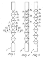
Figures 3, 4, 5 are three views of a tube according to the invention obtained by turning such tube with respect toFigure 3 first through 45° and then through 90°; -
Figures 6, 7, 8 are sectional views taken respectively along the lines VI-VI, VII-VII, VIII-VIII ofFigure 3 ; -
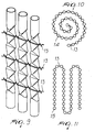
Figure 9 is a view of an embodiment of the connection of the tubes; -
Figures 10 and 11 are views of different configurations of the tubes which form the tube bundle. - With reference to
Figures 1 and 2 , the reference numeral 1 generally designates a heat exchanger according to the invention, which is designed to be inserted in an extracorporeal blood circuit and comprises a tube bundle formed bytubes disks 4 and 5 located at the end faces of anouter jacket 6, which delimits, together with the disks, a portion of space which contains the tube bundle and is designed to be crossed by the fluid for exchanging heat with the blood, constituted by water, along the arrows shown in the figures. - All the
tubes reference numeral 7, is described with reference toFigures 3 to 8 . - Such tube has a plurality of consecutive crimps organized into two series: a first series of
parallel crimps parallel crimps - This leads to a progressive variation of the shape of the blood passage section, shown in
Figures 6, 7, 8 by highlighting cross-sections 10, 11, 12, which induces the blood to move with a turbulent flow, as occurs also for the water as well, with a much higher heat exchange efficiency than that which occurs in known exchangers which use cylindrical tubes, which therefore produce a laminar flow of blood and of the water. - It becomes thus possible to provide compact devices which are highly advantageous in terms of space occupation, of quantity of blood contained, known as priming, and of resistance offered to the flow of the blood.
- The device according to the invention can be provided with wire-
like elements 13 for connecting one another the individual tubes of the bundle, arranged so as to come into contact with said tubes at coplanar crimps, and thus properly kept in position. - By adopting the wire-
like elements 13 it becomes easy to give to the tubes of the tube bundle a prearranged organization, as occurs fortubes 14 ofFigure 10 ortubes 15 ofFigure 11 . - The described invention is susceptible of numerous modifications and variations, all of which are within the scope of the appended claims: thus, for example, the directions of the crimps can be offset in any manner and moreover the axes of the tubes, instead of being parallel, may be oblique; moreover, the invention, besides being provided for single use, can be provided with means for coupling to different devices which are integrated in a single structure, as is for example the case of an oxygenation apparatus or of a cardiotomy reservoir used within an extracorporeal blood circuit.
- Where technical features mentioned in any claim are followed by reference signs, those reference signs have been included for the sole purpose of increasing the intelligibility of the claims and accordingly, such reference signs do not have any limiting effect on the interpretation of each element identified by way of example by such reference signs.
Claims (8)
- A heat exchanger for medical use, comprising a tube bundle formed by a plurality of tubes (2, 3, 7) having a straight axis for the conveyance of a primary fluid, which are embedded at their ends in disks (4, 5) located at the end faces of an outer jacket (6) which is adapted to delimit, together with said disks, a portion of space for the containment of said tube bundle which is designed to be crossed by a secondary fluid, each tube (2, 3, 7) having, at least at a portion of its length, a plurality of consecutive crimps (8a-8c, 9a-9c) adapted to determine a progressive variation of the shape of the passage section, characterized in that each portion of said tube (2, 3, 7), forming said passage sections, and which is comprised between two consecutive ones (8a, 9a; 8b, 9b;...) of said crimps is shaped as a prismoid with two opposite faces in which the vertices of the prismoid form opposite rectangles that are joined to each other by isosceles trapezoids.
- The heat exchanger according to claim 1, characterized in that each tube (2, 3, 7) has a plurality of crimps (8a-8c, 9a-9c) with mutually offset directions.
- The heat exchanger according to one or more of the preceding claims, characterized in that each tube (2, 3, 7) has a first series of parallel crimps (8a-8c) alternated with a second series ( 9a-9c) of parallel crimps, the directions of the crimps (8a-8c, 9a-9c) of the two series being offset.
- The heat exchanger according to one or more of the preceding claims, characterized in that each tube (2, 3, 7) has a first series (8a-8c)of parallel crimps alternated with a second series (9a-9c) of parallel crimps, the directions of the crimps (8a-8c, 9a-9c) of the two series being offset substantially by 90°.
- The heat exchanger according to one or more of the preceding claims, characterized by the presence of at least one wire-like element (13) for mutual connection of the individual tubes (2, 3, 7) of the bundle, arranged so as to come into contact with said tubes at coplanar crimps.
- The heat exchanger according to one or more of the preceding claims, characterized in that the tubes (2, 3, 7) having a straight axis of the bundle have parallel axes.
- The heat exchanger according to one or more of the preceding claims, characterized in that the tubes (2, 3, 7) having a straight axis of the bundle have oblique axes.
- The heat exchanger according to one or more of the preceding claims, characterized in that it comprises means for coupling to different devices integrated in a single structure.
Applications Claiming Priority (1)
| Application Number | Priority Date | Filing Date | Title |
|---|---|---|---|
| IT001899A ITMI20051899A1 (en) | 2005-10-10 | 2005-10-10 | HEAT EXCHANGE DEVICE FOR MEDICAL USE |
Publications (2)
| Publication Number | Publication Date |
|---|---|
| EP1772164A1 EP1772164A1 (en) | 2007-04-11 |
| EP1772164B1 true EP1772164B1 (en) | 2009-12-23 |
Family
ID=37673602
Family Applications (1)
| Application Number | Title | Priority Date | Filing Date |
|---|---|---|---|
| EP06019674A Active EP1772164B1 (en) | 2005-10-10 | 2006-09-20 | Heat exchanger for medical use |
Country Status (7)
| Country | Link |
|---|---|
| US (1) | US7748438B2 (en) |
| EP (1) | EP1772164B1 (en) |
| JP (1) | JP4607084B2 (en) |
| AT (1) | ATE452672T1 (en) |
| CA (1) | CA2561068C (en) |
| DE (1) | DE602006011254D1 (en) |
| IT (1) | ITMI20051899A1 (en) |
Families Citing this family (13)
| Publication number | Priority date | Publication date | Assignee | Title |
|---|---|---|---|---|
| EP1930034B1 (en) | 2006-12-07 | 2012-11-14 | Thoratec LLC | An integrated centrifugal blood pump-oxygenator, an extracorporeal life support system and a method of de-bubbling and priming an extracorporeal life support system |
| US8234881B2 (en) * | 2008-08-28 | 2012-08-07 | Johnson Controls Technology Company | Multichannel heat exchanger with dissimilar flow |
| US20100294474A1 (en) * | 2009-05-22 | 2010-11-25 | Sumito Furuya Hirota | Heat exchanger tube |
| JP5321257B2 (en) * | 2009-06-09 | 2013-10-23 | 株式会社ジェイ・エム・エス | Medical heat exchanger, method for manufacturing the same, and oxygenator |
| US8455242B2 (en) | 2010-02-22 | 2013-06-04 | Hyclone Laboratories, Inc. | Mixing system with condenser |
| US9284841B1 (en) * | 2011-07-14 | 2016-03-15 | Julie C. Vickers | Disposable heat exchanger assembly for sterile and aseptic biotechnology and pharmaceutical manufacturing applications |
| CN106232198B (en) | 2014-03-21 | 2019-06-07 | 生命科技股份有限公司 | Condenser Systems for Fluid Handling Systems |
| EP4269554B1 (en) | 2014-03-21 | 2025-10-22 | Life Technologies Corporation | Gas filter systems for fluid processing systems |
| US9457306B2 (en) | 2014-10-07 | 2016-10-04 | Life Technologies Corporation | Regulated vacuum off-gassing of gas filter for fluid processing system and related methods |
| EP3397389B1 (en) | 2015-12-29 | 2024-05-15 | Life Technologies Corporation | Method and system for separating magnetic particles from a fluid |
| USD945579S1 (en) * | 2017-12-20 | 2022-03-08 | Rheem Manufacturing Company | Heat exchanger tube with fins |
| EP4306892A1 (en) * | 2022-07-13 | 2024-01-17 | Hamilton Sundstrand Corporation | Heat exchanger channel |
| CN116202344A (en) * | 2023-01-12 | 2023-06-02 | 南通三圣石墨设备科技股份有限公司 | Methanol vaporizer |
Family Cites Families (8)
| Publication number | Priority date | Publication date | Assignee | Title |
|---|---|---|---|---|
| US2086222A (en) * | 1936-05-28 | 1937-07-06 | Gen Chemical Corp | Heat exchange apparatus |
| US4056143A (en) * | 1972-11-08 | 1977-11-01 | The Plessey Company Limited | Heat exchange apparatus |
| DE2608623A1 (en) * | 1976-03-02 | 1977-09-15 | Becker Apparatebau Geb | Mash cooler with coolant surrounding pipe for flow of mash - with constricted and wide zones one behind another along pipe |
| AU1334600A (en) * | 1998-11-02 | 2000-05-22 | Lifestream International, Inc. | Cardioplegia heat exchanger |
| CA2289428C (en) * | 1998-12-04 | 2008-12-09 | Beckett Gas, Inc. | Heat exchanger tube with integral restricting and turbulating structure |
| JP3326405B2 (en) * | 1999-04-21 | 2002-09-24 | 協和ステンレス株式会社 | Pipes and heat exchangers |
| US6840074B2 (en) * | 1999-04-21 | 2005-01-11 | Tojo Kamino | Pipe and heat exchanger, pipe manufacturing device, and pipe manufacturing method |
| JP4337573B2 (en) * | 2004-02-10 | 2009-09-30 | 株式会社ジェイ・エム・エス | Heat exchanger, method for producing the same, and heart-lung machine |
-
2005
- 2005-10-10 IT IT001899A patent/ITMI20051899A1/en unknown
-
2006
- 2006-09-20 EP EP06019674A patent/EP1772164B1/en active Active
- 2006-09-20 AT AT06019674T patent/ATE452672T1/en not_active IP Right Cessation
- 2006-09-20 DE DE602006011254T patent/DE602006011254D1/en active Active
- 2006-09-25 US US11/526,048 patent/US7748438B2/en active Active
- 2006-09-27 CA CA2561068A patent/CA2561068C/en active Active
- 2006-10-05 JP JP2006273995A patent/JP4607084B2/en not_active Expired - Fee Related
Also Published As
| Publication number | Publication date |
|---|---|
| ATE452672T1 (en) | 2010-01-15 |
| US20070079955A1 (en) | 2007-04-12 |
| ITMI20051899A1 (en) | 2007-04-11 |
| CA2561068A1 (en) | 2007-04-10 |
| DE602006011254D1 (en) | 2010-02-04 |
| CA2561068C (en) | 2016-08-02 |
| US7748438B2 (en) | 2010-07-06 |
| JP4607084B2 (en) | 2011-01-05 |
| EP1772164A1 (en) | 2007-04-11 |
| JP2007105464A (en) | 2007-04-26 |
Similar Documents
| Publication | Publication Date | Title |
|---|---|---|
| EP1772164A1 (en) | Heat exchanger for medical use | |
| US20150300746A1 (en) | Heat exchanger tube and heat exchanger employing the same | |
| EP2351979B1 (en) | Heat Exchanger comprising three concentric tubes | |
| EP2981780B1 (en) | Plate heat exchanger and method for constructing multiple passes in the plate heat exchanger | |
| EP2151653A2 (en) | Heat exchanger having winding micro-channels | |
| JP2005512009A5 (en) | ||
| CN100557366C (en) | Heat pipe with internal retaining wall for wicking component | |
| GB0606996D0 (en) | Multi-fluid heat exchanger and method of making same | |
| KR950014830A (en) | heat transmitter | |
| ES2127472T3 (en) | STACKED DUPLEX HEAT EXCHANGER. | |
| WO2003083395A1 (en) | Micro-channel heat exchanger | |
| EP1498683A3 (en) | Multi-pass parallel-tubes heat exchanger | |
| CA2425586A1 (en) | Heat exchanger having improved header | |
| JP5818397B2 (en) | Plate heat exchanger | |
| KR20050041979A (en) | Flexible tube arrangement-heat exchanger design | |
| EP1557631A3 (en) | Heat exchanger | |
| WO2016075352A1 (en) | Double-helix heat exchanger | |
| HK1103225A (en) | Heat exchanger for medical use | |
| KR20170024097A (en) | Header for exchanger bundle of a heat exchanger | |
| US20130192805A1 (en) | Twist Vane Counter-Parallel Flow Heat Exchanger Apparatus And Method | |
| EP3581868A1 (en) | Water heat exchanger and gas cooler | |
| EP2896925A1 (en) | Heat exchanger | |
| GB2234806A (en) | Heat exchangers | |
| JP2004293873A (en) | Heat exchanger | |
| JP2008256340A (en) | Multitubular heat exchanger with truncated cone shaped tube plate and spiral bent tube |
Legal Events
| Date | Code | Title | Description |
|---|---|---|---|
| PUAI | Public reference made under article 153(3) epc to a published international application that has entered the european phase |
Free format text: ORIGINAL CODE: 0009012 |
|
| AK | Designated contracting states |
Kind code of ref document: A1 Designated state(s): AT BE BG CH CY CZ DE DK EE ES FI FR GB GR HU IE IS IT LI LT LU LV MC NL PL PT RO SE SI SK TR |
|
| AX | Request for extension of the european patent |
Extension state: AL BA HR MK YU |
|
| RIN1 | Information on inventor provided before grant (corrected) |
Inventor name: GHELLI, NICOLA Inventor name: BALANZONI, ROBERTO Inventor name: COSTA MAIANTI, EDGARDO |
|
| 17P | Request for examination filed |
Effective date: 20071009 |
|
| REG | Reference to a national code |
Ref country code: HK Ref legal event code: DE Ref document number: 1103225 Country of ref document: HK |
|
| AKX | Designation fees paid |
Designated state(s): AT BE BG CH CY CZ DE DK EE ES FI FR GB GR HU IE IS IT LI LT LU LV MC NL PL PT RO SE SI SK TR |
|
| GRAP | Despatch of communication of intention to grant a patent |
Free format text: ORIGINAL CODE: EPIDOSNIGR1 |
|
| RIN1 | Information on inventor provided before grant (corrected) |
Inventor name: COSTA MAIANTI, EDGARDO Inventor name: BALANZONI, ROBERTO Inventor name: GHELLI, NICOLA |
|
| GRAS | Grant fee paid |
Free format text: ORIGINAL CODE: EPIDOSNIGR3 |
|
| GRAA | (expected) grant |
Free format text: ORIGINAL CODE: 0009210 |
|
| AK | Designated contracting states |
Kind code of ref document: B1 Designated state(s): AT BE BG CH CY CZ DE DK EE ES FI FR GB GR HU IE IS IT LI LT LU LV MC NL PL PT RO SE SI SK TR |
|
| REG | Reference to a national code |
Ref country code: GB Ref legal event code: FG4D |
|
| REG | Reference to a national code |
Ref country code: CH Ref legal event code: EP |
|
| REG | Reference to a national code |
Ref country code: IE Ref legal event code: FG4D |
|
| REF | Corresponds to: |
Ref document number: 602006011254 Country of ref document: DE Date of ref document: 20100204 Kind code of ref document: P |
|
| REG | Reference to a national code |
Ref country code: NL Ref legal event code: VDEP Effective date: 20091223 |
|
| PG25 | Lapsed in a contracting state [announced via postgrant information from national office to epo] |
Ref country code: SE Free format text: LAPSE BECAUSE OF FAILURE TO SUBMIT A TRANSLATION OF THE DESCRIPTION OR TO PAY THE FEE WITHIN THE PRESCRIBED TIME-LIMIT Effective date: 20091223 Ref country code: LT Free format text: LAPSE BECAUSE OF FAILURE TO SUBMIT A TRANSLATION OF THE DESCRIPTION OR TO PAY THE FEE WITHIN THE PRESCRIBED TIME-LIMIT Effective date: 20091223 Ref country code: FI Free format text: LAPSE BECAUSE OF FAILURE TO SUBMIT A TRANSLATION OF THE DESCRIPTION OR TO PAY THE FEE WITHIN THE PRESCRIBED TIME-LIMIT Effective date: 20091223 |
|
| LTIE | Lt: invalidation of european patent or patent extension |
Effective date: 20091223 |
|
| PG25 | Lapsed in a contracting state [announced via postgrant information from national office to epo] |
Ref country code: LV Free format text: LAPSE BECAUSE OF FAILURE TO SUBMIT A TRANSLATION OF THE DESCRIPTION OR TO PAY THE FEE WITHIN THE PRESCRIBED TIME-LIMIT Effective date: 20091223 Ref country code: SI Free format text: LAPSE BECAUSE OF FAILURE TO SUBMIT A TRANSLATION OF THE DESCRIPTION OR TO PAY THE FEE WITHIN THE PRESCRIBED TIME-LIMIT Effective date: 20091223 Ref country code: PL Free format text: LAPSE BECAUSE OF FAILURE TO SUBMIT A TRANSLATION OF THE DESCRIPTION OR TO PAY THE FEE WITHIN THE PRESCRIBED TIME-LIMIT Effective date: 20091223 |
|
| PG25 | Lapsed in a contracting state [announced via postgrant information from national office to epo] |
Ref country code: AT Free format text: LAPSE BECAUSE OF FAILURE TO SUBMIT A TRANSLATION OF THE DESCRIPTION OR TO PAY THE FEE WITHIN THE PRESCRIBED TIME-LIMIT Effective date: 20091223 |
|
| PG25 | Lapsed in a contracting state [announced via postgrant information from national office to epo] |
Ref country code: PT Free format text: LAPSE BECAUSE OF FAILURE TO SUBMIT A TRANSLATION OF THE DESCRIPTION OR TO PAY THE FEE WITHIN THE PRESCRIBED TIME-LIMIT Effective date: 20100423 Ref country code: EE Free format text: LAPSE BECAUSE OF FAILURE TO SUBMIT A TRANSLATION OF THE DESCRIPTION OR TO PAY THE FEE WITHIN THE PRESCRIBED TIME-LIMIT Effective date: 20091223 Ref country code: NL Free format text: LAPSE BECAUSE OF FAILURE TO SUBMIT A TRANSLATION OF THE DESCRIPTION OR TO PAY THE FEE WITHIN THE PRESCRIBED TIME-LIMIT Effective date: 20091223 Ref country code: BG Free format text: LAPSE BECAUSE OF FAILURE TO SUBMIT A TRANSLATION OF THE DESCRIPTION OR TO PAY THE FEE WITHIN THE PRESCRIBED TIME-LIMIT Effective date: 20100323 Ref country code: RO Free format text: LAPSE BECAUSE OF FAILURE TO SUBMIT A TRANSLATION OF THE DESCRIPTION OR TO PAY THE FEE WITHIN THE PRESCRIBED TIME-LIMIT Effective date: 20091223 Ref country code: ES Free format text: LAPSE BECAUSE OF FAILURE TO SUBMIT A TRANSLATION OF THE DESCRIPTION OR TO PAY THE FEE WITHIN THE PRESCRIBED TIME-LIMIT Effective date: 20100403 Ref country code: IS Free format text: LAPSE BECAUSE OF FAILURE TO SUBMIT A TRANSLATION OF THE DESCRIPTION OR TO PAY THE FEE WITHIN THE PRESCRIBED TIME-LIMIT Effective date: 20100423 |
|
| PG25 | Lapsed in a contracting state [announced via postgrant information from national office to epo] |
Ref country code: CZ Free format text: LAPSE BECAUSE OF FAILURE TO SUBMIT A TRANSLATION OF THE DESCRIPTION OR TO PAY THE FEE WITHIN THE PRESCRIBED TIME-LIMIT Effective date: 20091223 Ref country code: SK Free format text: LAPSE BECAUSE OF FAILURE TO SUBMIT A TRANSLATION OF THE DESCRIPTION OR TO PAY THE FEE WITHIN THE PRESCRIBED TIME-LIMIT Effective date: 20091223 Ref country code: BE Free format text: LAPSE BECAUSE OF FAILURE TO SUBMIT A TRANSLATION OF THE DESCRIPTION OR TO PAY THE FEE WITHIN THE PRESCRIBED TIME-LIMIT Effective date: 20091223 |
|
| PG25 | Lapsed in a contracting state [announced via postgrant information from national office to epo] |
Ref country code: GR Free format text: LAPSE BECAUSE OF FAILURE TO SUBMIT A TRANSLATION OF THE DESCRIPTION OR TO PAY THE FEE WITHIN THE PRESCRIBED TIME-LIMIT Effective date: 20100324 Ref country code: CY Free format text: LAPSE BECAUSE OF FAILURE TO SUBMIT A TRANSLATION OF THE DESCRIPTION OR TO PAY THE FEE WITHIN THE PRESCRIBED TIME-LIMIT Effective date: 20091223 |
|
| PLBE | No opposition filed within time limit |
Free format text: ORIGINAL CODE: 0009261 |
|
| STAA | Information on the status of an ep patent application or granted ep patent |
Free format text: STATUS: NO OPPOSITION FILED WITHIN TIME LIMIT |
|
| 26N | No opposition filed |
Effective date: 20100924 |
|
| PG25 | Lapsed in a contracting state [announced via postgrant information from national office to epo] |
Ref country code: DK Free format text: LAPSE BECAUSE OF FAILURE TO SUBMIT A TRANSLATION OF THE DESCRIPTION OR TO PAY THE FEE WITHIN THE PRESCRIBED TIME-LIMIT Effective date: 20091223 |
|
| PG25 | Lapsed in a contracting state [announced via postgrant information from national office to epo] |
Ref country code: MC Free format text: LAPSE BECAUSE OF NON-PAYMENT OF DUE FEES Effective date: 20100930 |
|
| REG | Reference to a national code |
Ref country code: CH Ref legal event code: PL |
|
| PG25 | Lapsed in a contracting state [announced via postgrant information from national office to epo] |
Ref country code: IE Free format text: LAPSE BECAUSE OF NON-PAYMENT OF DUE FEES Effective date: 20100920 Ref country code: LI Free format text: LAPSE BECAUSE OF NON-PAYMENT OF DUE FEES Effective date: 20100930 Ref country code: CH Free format text: LAPSE BECAUSE OF NON-PAYMENT OF DUE FEES Effective date: 20100930 |
|
| PG25 | Lapsed in a contracting state [announced via postgrant information from national office to epo] |
Ref country code: HU Free format text: LAPSE BECAUSE OF FAILURE TO SUBMIT A TRANSLATION OF THE DESCRIPTION OR TO PAY THE FEE WITHIN THE PRESCRIBED TIME-LIMIT Effective date: 20100624 Ref country code: LU Free format text: LAPSE BECAUSE OF NON-PAYMENT OF DUE FEES Effective date: 20100920 |
|
| PG25 | Lapsed in a contracting state [announced via postgrant information from national office to epo] |
Ref country code: TR Free format text: LAPSE BECAUSE OF FAILURE TO SUBMIT A TRANSLATION OF THE DESCRIPTION OR TO PAY THE FEE WITHIN THE PRESCRIBED TIME-LIMIT Effective date: 20091223 |
|
| REG | Reference to a national code |
Ref country code: HK Ref legal event code: WD Ref document number: 1103225 Country of ref document: HK |
|
| REG | Reference to a national code |
Ref country code: DE Ref legal event code: R082 Ref document number: 602006011254 Country of ref document: DE Representative=s name: SCHAUMBURG & PARTNER PATENTANWAELTE GBR, DE Ref country code: DE Ref legal event code: R082 Ref document number: 602006011254 Country of ref document: DE Representative=s name: SCHAUMBURG UND PARTNER PATENTANWAELTE MBB, DE |
|
| REG | Reference to a national code |
Ref country code: FR Ref legal event code: PLFP Year of fee payment: 11 |
|
| REG | Reference to a national code |
Ref country code: FR Ref legal event code: PLFP Year of fee payment: 12 |
|
| REG | Reference to a national code |
Ref country code: FR Ref legal event code: PLFP Year of fee payment: 13 |
|
| P01 | Opt-out of the competence of the unified patent court (upc) registered |
Effective date: 20230527 |
|
| PGFP | Annual fee paid to national office [announced via postgrant information from national office to epo] |
Ref country code: GB Payment date: 20230927 Year of fee payment: 18 |
|
| PGFP | Annual fee paid to national office [announced via postgrant information from national office to epo] |
Ref country code: FR Payment date: 20230925 Year of fee payment: 18 |
|
| PGFP | Annual fee paid to national office [announced via postgrant information from national office to epo] |
Ref country code: DE Payment date: 20240927 Year of fee payment: 19 |
|
| GBPC | Gb: european patent ceased through non-payment of renewal fee |
Effective date: 20240920 |
|
| PG25 | Lapsed in a contracting state [announced via postgrant information from national office to epo] |
Ref country code: GB Free format text: LAPSE BECAUSE OF NON-PAYMENT OF DUE FEES Effective date: 20240920 |
|
| PG25 | Lapsed in a contracting state [announced via postgrant information from national office to epo] |
Ref country code: FR Free format text: LAPSE BECAUSE OF NON-PAYMENT OF DUE FEES Effective date: 20240930 |
|
| PGFP | Annual fee paid to national office [announced via postgrant information from national office to epo] |
Ref country code: IT Payment date: 20250923 Year of fee payment: 20 |