EP1771677B1 - Collier de serrage - Google Patents
Collier de serrage Download PDFInfo
- Publication number
- EP1771677B1 EP1771677B1 EP05757870A EP05757870A EP1771677B1 EP 1771677 B1 EP1771677 B1 EP 1771677B1 EP 05757870 A EP05757870 A EP 05757870A EP 05757870 A EP05757870 A EP 05757870A EP 1771677 B1 EP1771677 B1 EP 1771677B1
- Authority
- EP
- European Patent Office
- Prior art keywords
- pipes
- clamp
- elastic
- bodies
- elastic bodies
- Prior art date
- Legal status (The legal status is an assumption and is not a legal conclusion. Google has not performed a legal analysis and makes no representation as to the accuracy of the status listed.)
- Ceased
Links
- 230000003014 reinforcing effect Effects 0.000 claims abstract description 19
- 230000013011 mating Effects 0.000 claims abstract description 9
- 230000006835 compression Effects 0.000 claims description 19
- 238000007906 compression Methods 0.000 claims description 19
- 229920001971 elastomer Polymers 0.000 claims description 2
- 230000014509 gene expression Effects 0.000 description 12
- 239000000446 fuel Substances 0.000 description 7
- 238000010521 absorption reaction Methods 0.000 description 5
- 230000000694 effects Effects 0.000 description 5
- 238000001816 cooling Methods 0.000 description 3
- 230000006866 deterioration Effects 0.000 description 3
- 238000000034 method Methods 0.000 description 3
- 239000012530 fluid Substances 0.000 description 2
- 229920001084 poly(chloroprene) Polymers 0.000 description 2
- 239000000853 adhesive Substances 0.000 description 1
- 230000001070 adhesive effect Effects 0.000 description 1
- 238000013016 damping Methods 0.000 description 1
- 239000013536 elastomeric material Substances 0.000 description 1
- 238000001914 filtration Methods 0.000 description 1
- 239000000463 material Substances 0.000 description 1
- 239000011347 resin Substances 0.000 description 1
- 229920005989 resin Polymers 0.000 description 1
- 238000003466 welding Methods 0.000 description 1
Images


Classifications
-
- F—MECHANICAL ENGINEERING; LIGHTING; HEATING; WEAPONS; BLASTING
- F16—ENGINEERING ELEMENTS AND UNITS; GENERAL MEASURES FOR PRODUCING AND MAINTAINING EFFECTIVE FUNCTIONING OF MACHINES OR INSTALLATIONS; THERMAL INSULATION IN GENERAL
- F16L—PIPES; JOINTS OR FITTINGS FOR PIPES; SUPPORTS FOR PIPES, CABLES OR PROTECTIVE TUBING; MEANS FOR THERMAL INSULATION IN GENERAL
- F16L3/00—Supports for pipes, cables or protective tubing, e.g. hangers, holders, clamps, cleats, clips, brackets
- F16L3/22—Supports for pipes, cables or protective tubing, e.g. hangers, holders, clamps, cleats, clips, brackets specially adapted for supporting a number of parallel pipes at intervals
- F16L3/223—Supports for pipes, cables or protective tubing, e.g. hangers, holders, clamps, cleats, clips, brackets specially adapted for supporting a number of parallel pipes at intervals each support having one transverse base for supporting the pipes
- F16L3/2235—Supports for pipes, cables or protective tubing, e.g. hangers, holders, clamps, cleats, clips, brackets specially adapted for supporting a number of parallel pipes at intervals each support having one transverse base for supporting the pipes each pipe being supported by a common element fastened to the base
-
- F—MECHANICAL ENGINEERING; LIGHTING; HEATING; WEAPONS; BLASTING
- F16—ENGINEERING ELEMENTS AND UNITS; GENERAL MEASURES FOR PRODUCING AND MAINTAINING EFFECTIVE FUNCTIONING OF MACHINES OR INSTALLATIONS; THERMAL INSULATION IN GENERAL
- F16L—PIPES; JOINTS OR FITTINGS FOR PIPES; SUPPORTS FOR PIPES, CABLES OR PROTECTIVE TUBING; MEANS FOR THERMAL INSULATION IN GENERAL
- F16L3/00—Supports for pipes, cables or protective tubing, e.g. hangers, holders, clamps, cleats, clips, brackets
- F16L3/22—Supports for pipes, cables or protective tubing, e.g. hangers, holders, clamps, cleats, clips, brackets specially adapted for supporting a number of parallel pipes at intervals
- F16L3/237—Supports for pipes, cables or protective tubing, e.g. hangers, holders, clamps, cleats, clips, brackets specially adapted for supporting a number of parallel pipes at intervals for two pipes
-
- F—MECHANICAL ENGINEERING; LIGHTING; HEATING; WEAPONS; BLASTING
- F16—ENGINEERING ELEMENTS AND UNITS; GENERAL MEASURES FOR PRODUCING AND MAINTAINING EFFECTIVE FUNCTIONING OF MACHINES OR INSTALLATIONS; THERMAL INSULATION IN GENERAL
- F16L—PIPES; JOINTS OR FITTINGS FOR PIPES; SUPPORTS FOR PIPES, CABLES OR PROTECTIVE TUBING; MEANS FOR THERMAL INSULATION IN GENERAL
- F16L55/00—Devices or appurtenances for use in, or in connection with, pipes or pipe systems
- F16L55/02—Energy absorbers; Noise absorbers
- F16L55/033—Noise absorbers
- F16L55/035—Noise absorbers in the form of specially adapted hangers or supports
Definitions
- the invention relates to a clamp which holds a pipe through which a fluid flows in a fuel system, brake system, cooling system, or the like in an automobile or the like. More particularly, the invention relates to a clamp that is suitable for preventing vibrations from reaching a plurality of pipes by connecting and holding the pipes.
- Pipes such as fuel pipes, brake pipes, and cooling system pipes are typically disposed in an engine room and the like of an automobile. These pipes are subject to vibrations of the automobile. In order to prevent those vibrations from reaching the pipes, a method has been employed in which the pipes are held by clamps.
- One related pipe clamp is a resin clamp structured such that a clamp body is formed integrally with a pipe holding portion.
- the clamp sandwiches the pipe, such as a fuel pipe, at that pipe holding portion.
- Japanese Utility Model Publication No. 6-6253 proposes a clamp that includes a pair of clamp members that sandwich a plurality of pipes.
- This clamp is structured such that each clamp member includes an elastic body having a plurality of concave portions formed therein and a reinforcing plate that is fixed to an outer side surface of this elastic body.
- the pair of clamp members are then aligned with the pipes arranged in the concave portions of the elastic bodies such that the plurality of pipes are fixed in place at the concave portions.
- the clamp according to Japanese Utility Model Publication No. 6-6253 is structured to fix and hold a plurality of pipes at concave portions in an elastic body, thus making it possible to clamp vibrations acting on the held pipes.
- a clamp of a structure that holds pipes at concave portions in an elastic body works fine as long as the plurality of pipes all have the same outer diameter. If the plurality of pipes have different outer diameters, however, the pipes may become deformed as a result of the conditions such as the compressibility of the elastic body and the tightening allowance [(pipe diameter) - (concave portion diameter)]. Furthermore, the vibration absorption effect may not be able to be achieved.
- the tightening allowance for each pipe is the same. Therefore, when that tightening allowance is a dimension appropriate for a large diameter pipe, then less force is applied to a small diameter pipe such that the hold of the clamp becomes loose. As a result, the vibration absorption effect may be reduced. If, on the other hand, the tightening allowance is appropriate for the small diameter pipe, then the force applied to a large diameter pipe ends up being excessive, possibly resulting in deformation of the large diameter pipe. There is also a possibility of the small diameter pipe becoming deformed depending on amount of compression of the elastic body.
- the tightening allowance is the same for each pipe, the decrease in binding force between pipes of different diameters may become uneven if the pipes settle on the elastic body as it deteriorates over time. As a result, the hold of the clamp on the large diameter or small diameter pipe would become loose, such that the vibration absorption effect would no longer be able to be achieved.
- EP 0 638 756A describes a clamp composed of two articulated half-shells designed to trap and retain at least one tube, one of the shells being secured to a baseplate which is equipped with a member for fastening to the support.
- the device includes two vibration-damping means such as linings made of an elastomeric material which provide double acoustic filtration between the tube and the support, a first means being interposed between the tube and the shells, while a second means is interposed between the shell and the baseplate.
- the invention thus aims to provide a clamp which, when holding a plurality of pipes having different outer diameters, is able to hold all of the pipes with appropriate clamping force such that there is no fear of the pipes deforming, and is also able to achieve an excellent vibration absorption effect.
- the invention therefore provides a clamp as defined in appended claim 1.
- the invention was achieved by the discovery of the conditions for obtaining an excellent vibration absorption effect without the pipes deforming or the elastic bodies loosening when connecting and holding a plurality of pipes having different outer diameters, in a clamp which uses elastic bodies having concave portions formed therein.
- Dn the diameter of the pipes
- Rn the curvature radius of the concave portions of the elastic bodies
- LnI and Ln2 the distances from the mating faces of the elastic bodies to the reinforcing plates
- the material of the elastic bodies is not particularly limited. However, when used on pipes in the fuel system or the like, a strong clamping force is required so it is preferable to use a rubber such as chloroprene rubber for the elastic bodies.
- a clamp which includes a pair of clamp members that sandwich a plurality of pipes, each clamp member including an elastic body having a plurality of concave portions formed therein and a reinforcing plate fixed to the outer side surface of the elastic body
- the dimensions of each portion of the elastic bodies are set so that the compression ratio of the elastic bodies is the same for all of the pipes.
- all of the pipes are able to be uniformly held with an appropriate clamping force so that the pipes will not deform.
- the binding force will not decrease in one area more than in another even if settling of the elastic bodies occurs due to deterioration over time..
- a good clamping state is able to be maintained over an extended period of time.
- FIG. 1 is a vertical cross-sectional view illustrating a clamp according to a first exemplary embodiment of the invention in a disassembled state
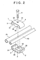
- FIG 2 is an exploded perspective view of the clamp shown in FIG. 1 ;
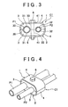
- FIG 3 is a front elevational view illustrating the clamp shown in FIG. 1 as it is used;
- FIG. 4 is a perspective view illustrating the clamp shown in FIG. 1 as it is used;
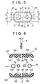
- FIG 5 is a view showing the dimensions of each portion of an elastic holding body used in the clamp shown in FIG 1 ;
- FIG 6 is a vertical cross-sectional view illustrating a clamp according to a second exemplary embodiment of the invention in a disassembled state
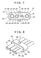
- FIG 7 is a front elevational view of the clamp shown in FIG. 6 as it is used;
- FIG 8 is a perspective view illustrating the clamp shown in FIG 6 as it is used
- FIG. 9 is a view showing the dimensions of each portion of an elastic holding body used in the clamp shown in FIG 6 ;
- FIG 10 is a vertical cross-sectional view illustrating a clamp according to a third exemplary embodiment of the invention in a disassembled state
- FIG 11 is a front elevational view of the clamp shown in FIG. 10 as it is used;
- FIG. 12 is a perspective view illustrating the clamp shown in FIG 10 as it is used.
- FIG 13 is a view showing the dimensions of each portion of an elastic holding body used in the clamp shown in FIG 10 .
- FIG 1 is a vertical cross-sectional view illustrating a clamp according to a first exemplary embodiment of the invention in a disassembled state.
- FIG 2 is an exploded perspective view of that clamp.
- FIG. 3 is a front elevational view, and
- FIG 4 is a perspective view, illustrating the clamp shown in FIG 1 as it is used.
- the clamp in this example is a clamp C1 which holds pipes such as fuel pipes and brake pipes in an automobile.
- the clamp C1 includes a pair of clamp members 1 and 2 which sandwich two pipes P1 and P2 having different diameters.
- Each clamp member 1 and 2 includes an elastic holding body 3 and a reinforcing plate 4.
- Each elastic holding body 3 and 3 is a manufactured product of chloroprene rubber. These two elastic holding bodies 3 and 3 are both formed symmetrical such that overall a generally rectangular block shaped member is formed when mating faces 30 of the elastic holding bodies 3 and 3 are matched up with each other. Two semi-circular concave portions 31 and 32 having different curvature radii are formed parallel to one another in the mating face 30 of each elastic holding body 3 and 3. When these two elastic holding bodies 3 and 3 are put together, circular holes are formed for fitting and holding two pipes P1 and P2 of large and small diameters, respectively. Also, a through hole 33 through which a bolt is inserted is formed in a center portion of each of the elastic holding bodies 3 and 3.
- Each reinforcing plate 4 and 4 is a member that is formed bent in a general U-shape which is fixed with an adhesive to an outer side surface of the elastic holding body 3.
- a through hole 41 through which a bolt is inserted is formed in a center portion of each reinforcing plate 4 and 4.
- a nut 5 is fixed by welding to the center portion of the outer surface of one of the reinforcing plates 4 (the reinforcing plate 4 of the clamp member 2 that is on the bottom in FIG 1 ).
- the centers of the through holes 41 in the reinforcing plates 4 and the center of the nut 5 are substantially aligned with the centers of the through holes 33 in the elastic holding bodies 3 and 3 described above.
- the curvature radii of the concave portions 31 and 32 of the elastic holding bodies 3 and 3 are made smaller than the radii of the pipes P1 and P2, respectively. Binding force on the pipes P1 and P2 is produced by the difference, i.e., the tightening allowance, between those curvature radii of the concave portions 31 and 32 and the radii of the pipes P1 and P2.
- the tightening allowance and compression ratio and the like of the elastic holding body 3 will be described later.
- the pair of clamp members 1 and 2 are first disassembled, and then one clamp member 2 (which has the nut 5) is arranged below the two pipes P1 and P2 and the other clamp member 1 is arranged above the two pipes P1 and P2, as shown in FIGS. 1 and 2 .
- the concave portions 31 and 32 of the elastic holding body 3 of each clamp member 1 and 2 are then aligned with the corresponding pipes P1 and P2, and a hexagonal bolt 6 is inserted from above into the through hole 41 in the reinforcing plate 4 and the through hole 33 in the elastic holding body 3 while the pair of clamp members 1 and 2 are matched up.
- each elastic holding body 3 and 3 is compressed an amount corresponding to the tightening allowance such that binding force is applied to each pipe P1 and P2 by the elastic force of the elastic holding bodies 3 and 3 and the pipes P1 and P2 are held by a strong clamping force.
- each portion of the elastic holding bodies 3 and 3 are set such that the compression ratio of the elastic holding bodies 3 and 3 which hold the two pipes P1 and P2 is the same for both the large diameter pipe P1 and the small diameter pipe P2.
- the dimensions of each portion of the elastic holding bodies 3 and 3 are set such that the operational expression (1) for a compression ratio ⁇ below is satisfied.
- the dimensions of each portion of the elastic holding bodies 3 and 3 are set so as to satisfy this operational expression (2), such that the compression ratio of the elastic holding bodies 3 and 3 becomes the same at the large diameter pipe P1 and the small diameter pipe P2.
- the optimal compression ratio ⁇ of the elastic holding body 3 is first determined beforehand by testing or the like.
- the curvature radius R1 of the large diameter side concave portion 31 is determined from a recommended value of the tightening allowance (r1 - R1) of the large diameter pipe P1.
- the distance L1 on the large diameter side is obtained by the operation expression (2) above using that curvature radius R1, the radius r1 of the large diameter pipe P1, and the compression ratio ⁇ that was determined beforehand.
- the dimensions of each portion are obtained based on the tightening allowance of the large diameter pipe P1.
- the dimensions of each portion may be obtained based on the tightening allowance (i.e., the recommended value) of the small diameter pipe P2.
- the curvature radii R1 and R2 of the concave portions 31, 32 may be determined from the recommended values of the tightening allowances (r1 - R1) and (r2 - R2) of the pipes P1 and P2, respectively, and the distances L1 and L2 may be obtained by the operational expression (2) using the curvature radii R1 and R2, the radii r1 and r2 of the pipes P1 and P2, and the compression ratio ⁇ .
- the above example describes a clamp which holds two pipes P1 and P2.
- the invention is not limited to this, however, i.e., the number of pipes connected and held may alternatively be three or more.
- the invention may also be applied to a clamp C2 which connects and holds four pipes P1 to P4 having different diameters, as described in a second exemplary embodiment illustrated in FIGS. 6 to 9 .
- FIG 10 is a vertical cross-sectional view illustrating a clamp according to a third exemplary embodiment of the invention in a disassembled state.
- FIG 11 is a front elevational view
- FIG 12 is a perspective view, of the clamp shown in FIG 10 as it is used.
- Clamp C3 in this example is characterised in that , in the structure shown in FIGS. 1 to 5 described above, elastic holding bodies 213 and 223 as well as reinforcing portions 214 and 224 of a pair of clamp members 201 and 202 are asymmetrical with respect to one another, and the distance L11 (see FIG 13 ) of one of the elastic holding bodies 213 (i.e., the elastic holding body on the upper side in FIG 10 ) is shorter than the distance L12 (see FIG 13 ) of the other elastic holding body 223 (i.e., the elastic holding body on the lower side in FIG. 10 ).
- the other structure is the same as that of clamp C1 shown in FIGS. 1 to 5 .
- the pair of clamp members are separate bodies, but the invention is not limited to this. That is, the pair of clamp members may be an integrated structure in which they are connected via a hinge or the like, such that they connect and hold a plurality of pipes by opening and closing.
- the invention is not limited to a clamp that connects and holds pipes for an automobile, such as fuel pipes and brake pipes in an automobile.
- the invention may also be applied to a clamp that connects and holds other various types of pipes used in objects aside from automobiles.
- the clamp of this invention can be used for connecting and holding pipes through which fluid flows in a fuel system, brake system, or cooling system or the like in an automobile or the like.
- the clamp of the invention can effectively be used to connect and hold a plurality of pipes having different diameters.
Landscapes
- Engineering & Computer Science (AREA)
- General Engineering & Computer Science (AREA)
- Mechanical Engineering (AREA)
- Supports For Pipes And Cables (AREA)
- Mutual Connection Of Rods And Tubes (AREA)
- Clamps And Clips (AREA)
Abstract
Claims (4)
- Collier de serrage comportant une paire d'éléments de serrage (1, 2; 101, 102; 201, 202) et une pluralité de tuyaux (P1, P2; P3, P4) ayant des section transversale cylindriques de diamètres différents qui sont pris en sandwich par les éléments de serrage, chacun des éléments de serrage (1, 2; 101, 102; 201, 202) incluant un corps élastique (3; 103; 213, 223) comportant une pluralité de parties concaves (31, 32; 131, 132, 133, 134; 231, 232, 233, 234) et une plaque de renforcement (4; 104; 214, 224) fixée sur une surface latérale extérieure du corps élastique (3; 103; 213, 223), le collier de serrage étant structuré pour supporter la pluralité de tuyaux (P1, P2; P3, P4) dans pluralité de parties concaves (31, 32; 131, 132, 133, 134; 231, 232, 233, 234) en alignant la paire d'éléments de serrage (1, 2; 101, 102) quand les tuyaux (P1, P2; P3, P4) sont agencés dans les parties concaves (31, 32; 131, 132, 133, 134; 231, 232, 233, 234) des corps élastique (3; 103; 213, 223), caractérisé en ce que :quand un diamètre d'un nième (n = un entier positif (1, 2, 3...)) tuyau, parmi la pluralité de tuyaux (P1, P2; P3, P4), est désigné par un caractère de référence Dn, un rayon de courbure de la partie concave (31, 32; 131, 132, 133, 134; 231, 232, 233, 234) qui supporte le nième tuyau est désigné par le caractère de référence Rn, et des distances, dans une direction orthogonale à des faces d'accouplement des corps élastique (3; 103; 213; 223) à travers un centre de support de tuyau d'une nième partie concave, des faces d'accouplement des corps élastique (3; 103) à des surfaces latérales intérieures d'une paire de plaques de renforcement (4; 104; 214, 224) sont désignées par les caractères de référence Ln1 et Ln2, respectivement, le rapport de compression des corps élastique (3; 103; 213; 223) satisfait !a relation [(D1 - 2R1) / (L11 + L12 - 2R1) = (D2 - 2R2) / (L21 + L22 - 2R2) = ... = (Dn - 2Rn) / (Ln1 + Ln2 - 2Rn)].
- Collier de serrage selon la revendication 1, dans lequel le corps élastique (3; 103; 213, 223) est du caoutchouc.
- Collier de serrage selon la revendication .1 ou 2, dans lequel les corps élastique (3; 103) et les plaques de renforcement (4; 104) de la paire d'éléments de serrage (1, 2; 101, 102) sont asymétriques les uns par rapport aux autres.
- Collier de serrage selon l'une quelconque des revendications 1 à 3, dans lequel le collier de serrage relie et supporte des tuyaux (P1, P2; P3, P4) pour une automobile.
Applications Claiming Priority (2)
| Application Number | Priority Date | Filing Date | Title |
|---|---|---|---|
| JP2004216303A JP4631338B2 (ja) | 2004-07-23 | 2004-07-23 | クランプ |
| PCT/IB2005/002132 WO2006011031A1 (fr) | 2004-07-23 | 2005-07-04 | Collier de serrage |
Publications (2)
| Publication Number | Publication Date |
|---|---|
| EP1771677A1 EP1771677A1 (fr) | 2007-04-11 |
| EP1771677B1 true EP1771677B1 (fr) | 2010-12-22 |
Family
ID=34972550
Family Applications (1)
| Application Number | Title | Priority Date | Filing Date |
|---|---|---|---|
| EP05757870A Ceased EP1771677B1 (fr) | 2004-07-23 | 2005-07-04 | Collier de serrage |
Country Status (7)
| Country | Link |
|---|---|
| US (1) | US7530536B2 (fr) |
| EP (1) | EP1771677B1 (fr) |
| JP (1) | JP4631338B2 (fr) |
| AR (1) | AR049596A1 (fr) |
| DE (1) | DE602005025486D1 (fr) |
| WO (1) | WO2006011031A1 (fr) |
| ZA (1) | ZA200700212B (fr) |
Families Citing this family (37)
| Publication number | Priority date | Publication date | Assignee | Title |
|---|---|---|---|---|
| KR100783514B1 (ko) * | 2006-03-21 | 2007-12-07 | 현대자동차주식회사 | 진동 절연 장치 |
| US20080121764A1 (en) * | 2006-09-29 | 2008-05-29 | Igor Komsitsky | Line Block Supports and Methods and Apparatus for Making and Using and Reconfiguring for Alternate Sizes of Payload Line Block Supports |
| DE202007004729U1 (de) | 2007-03-30 | 2007-07-12 | Woco Avs Gmbh | Vorrichtung zum Halten wenigstens eines langgestreckten Bauteils |
| BRPI0701686B1 (pt) * | 2007-05-07 | 2019-04-24 | Embraco Indústria De Compressores E Soluções Em Refrigeração Ltda | Arranjo de montagem para os cabos de energização de um motor elétrico de compressor de refrigeração |
| US20090319235A1 (en) * | 2008-04-17 | 2009-12-24 | Maclean-Fogg Company | Fiberglass Cross Arm And Method Of Selecting Same |
| US7922012B2 (en) * | 2008-07-24 | 2011-04-12 | Power Bus Way Ltd. | Cable tray |
| GB0906071D0 (en) * | 2009-04-08 | 2009-05-20 | Airbus Uk Ltd | Cable raceway |
| JP5602460B2 (ja) * | 2010-03-05 | 2014-10-08 | 株式会社ニフコ | クランプ |
| US20110226801A1 (en) * | 2010-03-19 | 2011-09-22 | Christy Smith-Heskel | Dispenser and associated methods |
| EP2573277B1 (fr) * | 2010-05-17 | 2017-02-15 | Volvo Construction Equipment AB | Disposition de fixation de tuyau hydraulique d'un engin de construction |
| JP5177201B2 (ja) * | 2010-10-20 | 2013-04-03 | コベルコ建機株式会社 | 建設機械の配管クランプ |
| GB2492836B (en) * | 2011-07-14 | 2013-07-03 | Subsea 7 Uk Service Company Ltd | Improvements relating to pipelaying |
| JP5870445B2 (ja) * | 2011-11-18 | 2016-03-01 | ポップリベット・ファスナー株式会社 | アース機能付パイプ取付具 |
| WO2013078480A1 (fr) * | 2011-11-27 | 2013-05-30 | Stryker Corporation | Fauteuil roulant |
| JP5923351B2 (ja) * | 2012-03-16 | 2016-05-24 | 株式会社Adeka | 銅膜形成用組成物及び該組成物を用いた銅膜の製造方法 |
| US20140190911A1 (en) * | 2012-03-18 | 2014-07-10 | Matthew Dino Minuti | Device for securing chopsticks to dishwasher rack |
| DE102012216236A1 (de) * | 2012-09-13 | 2014-03-13 | Robert Bosch Gmbh | Halter zur Befestigung eines rohrförmigen Bauteils an einer Anbaustruktur |
| US9971120B2 (en) * | 2012-10-31 | 2018-05-15 | Commscope Technologies Llc | Anchoring cables to rack with cable clamp arrangements |
| US9038967B2 (en) | 2013-03-26 | 2015-05-26 | Solar Turbines Incorporated | Fluid line clamp |
| WO2014176499A1 (fr) * | 2013-04-25 | 2014-10-30 | Robert Atmar Keith Jr | Dispositif de serrage à contact minimal réduisant la corrosion permettant de supporter et de fixer des tuyaux |
| US9863556B2 (en) | 2013-04-25 | 2018-01-09 | Atmar Keith ROBERT, JR. | Corrosion reducing minimum contact clamp for supporting and securing tubing |
| US9142946B2 (en) * | 2013-06-27 | 2015-09-22 | Caterpillar Inc. | Cable retention system |
| FR3015625B1 (fr) * | 2013-12-20 | 2015-12-11 | Snecma | Bras de guidage d'elements de forme allongee, en particulier pour une turbomachine |
| WO2015105902A1 (fr) * | 2014-01-07 | 2015-07-16 | Kirkhill-Ta Co. | Ensemble bloc de ligne d'inter-verrouillage |
| DE102014100781A1 (de) * | 2014-01-23 | 2015-07-23 | Hans-Jürgen Guido | Schwingungsdämpfer |
| JP6454110B2 (ja) * | 2014-09-12 | 2019-01-16 | ポップリベット・ファスナー株式会社 | 防振クランプ |
| EP3221575B1 (fr) * | 2014-11-19 | 2021-01-06 | Vitesco Technologies GmbH | Ensemble rail de carburant pour un moteur à combustion interne |
| US20160290531A1 (en) * | 2015-03-31 | 2016-10-06 | Tektronix, Inc. | Cable restraint system |
| FR3049327B1 (fr) * | 2016-03-24 | 2018-08-17 | Akwel Sweden Ab | Procede de fabrication pour realiser un assemblage de support et tuyauterie |
| CN106286530B (zh) * | 2016-08-31 | 2018-03-13 | 北京术锐技术有限公司 | 一种多根杆的锁紧装置 |
| US10800540B2 (en) * | 2017-08-03 | 2020-10-13 | The Boeing Company | Transport element clamp system |
| US10161542B1 (en) | 2017-11-10 | 2018-12-25 | Cnh Industrial America Llc | Mounting hard lines to a vehicle frame |
| US10439381B1 (en) * | 2018-07-10 | 2019-10-08 | The Boeing Company | Electrical raceway system and associated wire bundle clamp system and method |
| CN108716570A (zh) * | 2018-07-26 | 2018-10-30 | 徐州徐工铁路装备有限公司 | 一种凿岩台车推进器软管支架 |
| CN109292280B (zh) * | 2018-09-11 | 2021-01-26 | 京东方科技集团股份有限公司 | 用于装载薄膜的盒和装载薄膜的方法 |
| CN113669543B (zh) * | 2021-07-19 | 2022-09-06 | 东北大学 | 一种具有减振耐温功能的航空发动机双联卡箍 |
| US20240218944A1 (en) * | 2023-01-04 | 2024-07-04 | Hubbell Incorporated | Multi-sized cable clamp |
Family Cites Families (18)
| Publication number | Priority date | Publication date | Assignee | Title |
|---|---|---|---|---|
| US2361943A (en) * | 1942-01-23 | 1944-11-07 | Adel Prec Products Corp | Conduit supporting and bonding block |
| US2355742A (en) * | 1942-09-21 | 1944-08-15 | Adel Prec Products Corp | Conduit supporting block |
| US2404531A (en) * | 1943-12-13 | 1946-07-23 | Adel Prec Products Corp | Conduit supporting block |
| US2354919A (en) * | 1944-04-08 | 1944-08-01 | Leroy Robert Bowles | Multiple clamping device |
| FR1373067A (fr) * | 1963-07-22 | 1964-09-25 | Brides d'attache à effet amortisseur pour tuyauteries | |
| US3592427A (en) * | 1969-01-09 | 1971-07-13 | Louis J Misuraca | Adaptable module, conduit and tube support |
| JPS5675383U (fr) * | 1979-11-13 | 1981-06-19 | ||
| JPH066253Y2 (ja) * | 1987-06-08 | 1994-02-16 | 日産自動車株式会社 | クランプ装置 |
| US5060810A (en) * | 1990-05-03 | 1991-10-29 | Gary Jones | Clamps for load braces |
| US5098047A (en) * | 1990-10-18 | 1992-03-24 | Flex Rail, Inc. | Tube clamp |
| JP2563935Y2 (ja) * | 1991-02-14 | 1998-03-04 | 株式会社ニフコ | 取付保持具 |
| JPH066253A (ja) | 1992-06-19 | 1994-01-14 | Hitachi Ltd | 無線通信装置 |
| FR2708705B1 (fr) | 1993-08-05 | 1995-10-20 | Peugeot | Dispositif de montage d'un tube sur un support. |
| US6193195B1 (en) * | 1999-04-26 | 2001-02-27 | Carl H. Owens | Clamp for metal tubing |
| DE19925772A1 (de) * | 1999-06-05 | 2000-12-07 | Hydac Befestigungstechnik Gmbh | Zweirohrschelle |
| JP2003329173A (ja) | 2002-05-15 | 2003-11-19 | Toyoda Gosei Co Ltd | 配管構造体およびホース保持具 |
| FR2843438B1 (fr) * | 2002-08-09 | 2005-02-11 | Amphenol Air Lb | Dispositif de maintien de tuyauteries |
| JP2005106162A (ja) * | 2003-09-30 | 2005-04-21 | Mitsubishi Automob Eng Co Ltd | パイプの保持構造 |
-
2004
- 2004-07-23 JP JP2004216303A patent/JP4631338B2/ja not_active Expired - Fee Related
-
2005
- 2005-07-04 ZA ZA200700212A patent/ZA200700212B/en unknown
- 2005-07-04 DE DE602005025486T patent/DE602005025486D1/de active Active
- 2005-07-04 US US11/631,523 patent/US7530536B2/en not_active Expired - Fee Related
- 2005-07-04 WO PCT/IB2005/002132 patent/WO2006011031A1/fr active Application Filing
- 2005-07-04 EP EP05757870A patent/EP1771677B1/fr not_active Ceased
- 2005-07-21 AR ARP050103024A patent/AR049596A1/es not_active Application Discontinuation
Also Published As
| Publication number | Publication date |
|---|---|
| JP4631338B2 (ja) | 2011-02-16 |
| AR049596A1 (es) | 2006-08-16 |
| JP2006038040A (ja) | 2006-02-09 |
| US7530536B2 (en) | 2009-05-12 |
| EP1771677A1 (fr) | 2007-04-11 |
| ZA200700212B (en) | 2008-06-25 |
| WO2006011031A1 (fr) | 2006-02-02 |
| US20080017761A1 (en) | 2008-01-24 |
| DE602005025486D1 (de) | 2011-02-03 |
Similar Documents
| Publication | Publication Date | Title |
|---|---|---|
| EP1771677B1 (fr) | Collier de serrage | |
| JP3899836B2 (ja) | 筒型ゴムマウント | |
| JP3525567B2 (ja) | 筒形防振支持体 | |
| US5857659A (en) | Mounting component for a cylindrical bushing and a mounting body | |
| CN101646880B (zh) | 防振装置 | |
| EP0229471A1 (fr) | Dispositif de fixation pour ressort à lame | |
| US5435532A (en) | Elastic suspension for attaching dynamically stressed function parts | |
| US6189874B1 (en) | X-configuration engine mounting | |
| EP0460529B1 (fr) | Dispositif à amortissement hydraulique | |
| JPH02292542A (ja) | 防振絶縁用弾性装置 | |
| US7819222B2 (en) | Device and method for attenuating energy along a conduit | |
| JPS61157430A (ja) | 支持構造体への振動ボデイの装着組立体 | |
| JP2000193004A (ja) | 防振装置 | |
| US20030173489A1 (en) | Exhaust pipe supporting device | |
| JP3650888B2 (ja) | 連結ロッドの製造方法および連結ロッド | |
| US7059353B2 (en) | Power steering noise and vibration attenuator | |
| US6910681B1 (en) | Retaining U-bolts to a tubular axle housing | |
| JP3772535B2 (ja) | ショックアブソーバ用取付金具 | |
| EP1030096A2 (fr) | Dispositif élastique de suspension avec amortisseur | |
| CN218377450U (zh) | 一种夹紧装置 | |
| JPH09317944A (ja) | 車両用エンジンの配管類のクランプ | |
| JP4130502B2 (ja) | 油圧式緩衝器用油圧管連結装置 | |
| WO2002042661A1 (fr) | Tige de raccordement | |
| JP2000046086A (ja) | 筒形防振マウント | |
| JPH10339342A (ja) | 防振装置 |
Legal Events
| Date | Code | Title | Description |
|---|---|---|---|
| PUAI | Public reference made under article 153(3) epc to a published international application that has entered the european phase |
Free format text: ORIGINAL CODE: 0009012 |
|
| 17P | Request for examination filed |
Effective date: 20070104 |
|
| AK | Designated contracting states |
Kind code of ref document: A1 Designated state(s): DE FR |
|
| RBV | Designated contracting states (corrected) |
Designated state(s): DE FR |
|
| DAX | Request for extension of the european patent (deleted) | ||
| 17Q | First examination report despatched |
Effective date: 20091216 |
|
| GRAP | Despatch of communication of intention to grant a patent |
Free format text: ORIGINAL CODE: EPIDOSNIGR1 |
|
| GRAS | Grant fee paid |
Free format text: ORIGINAL CODE: EPIDOSNIGR3 |
|
| GRAA | (expected) grant |
Free format text: ORIGINAL CODE: 0009210 |
|
| AK | Designated contracting states |
Kind code of ref document: B1 Designated state(s): DE FR |
|
| REF | Corresponds to: |
Ref document number: 602005025486 Country of ref document: DE Date of ref document: 20110203 Kind code of ref document: P |
|
| REG | Reference to a national code |
Ref country code: DE Ref legal event code: R096 Ref document number: 602005025486 Country of ref document: DE Effective date: 20110203 |
|
| PLBE | No opposition filed within time limit |
Free format text: ORIGINAL CODE: 0009261 |
|
| STAA | Information on the status of an ep patent application or granted ep patent |
Free format text: STATUS: NO OPPOSITION FILED WITHIN TIME LIMIT |
|
| 26N | No opposition filed |
Effective date: 20110923 |
|
| REG | Reference to a national code |
Ref country code: DE Ref legal event code: R097 Ref document number: 602005025486 Country of ref document: DE Effective date: 20110923 |
|
| REG | Reference to a national code |
Ref country code: DE Ref legal event code: R084 Ref document number: 602005025486 Country of ref document: DE Effective date: 20130410 |
|
| REG | Reference to a national code |
Ref country code: FR Ref legal event code: PLFP Year of fee payment: 12 |
|
| REG | Reference to a national code |
Ref country code: FR Ref legal event code: PLFP Year of fee payment: 13 |
|
| PGFP | Annual fee paid to national office [announced via postgrant information from national office to epo] |
Ref country code: FR Payment date: 20170613 Year of fee payment: 13 |
|
| PGFP | Annual fee paid to national office [announced via postgrant information from national office to epo] |
Ref country code: DE Payment date: 20170627 Year of fee payment: 13 |
|
| REG | Reference to a national code |
Ref country code: DE Ref legal event code: R119 Ref document number: 602005025486 Country of ref document: DE |
|
| PG25 | Lapsed in a contracting state [announced via postgrant information from national office to epo] |
Ref country code: FR Free format text: LAPSE BECAUSE OF NON-PAYMENT OF DUE FEES Effective date: 20180731 Ref country code: DE Free format text: LAPSE BECAUSE OF NON-PAYMENT OF DUE FEES Effective date: 20190201 |