EP1770870A1 - Verfahren und Vorrichtung zur Stromleitungskommunikation - Google Patents
Verfahren und Vorrichtung zur Stromleitungskommunikation Download PDFInfo
- Publication number
- EP1770870A1 EP1770870A1 EP05256179A EP05256179A EP1770870A1 EP 1770870 A1 EP1770870 A1 EP 1770870A1 EP 05256179 A EP05256179 A EP 05256179A EP 05256179 A EP05256179 A EP 05256179A EP 1770870 A1 EP1770870 A1 EP 1770870A1
- Authority
- EP
- European Patent Office
- Prior art keywords
- powerline
- widebands
- band
- network
- communication
- Prior art date
- Legal status (The legal status is an assumption and is not a legal conclusion. Google has not performed a legal analysis and makes no representation as to the accuracy of the status listed.)
- Granted
Links
- 230000006854 communication Effects 0.000 title claims description 173
- 238000004891 communication Methods 0.000 title claims description 172
- 238000000034 method Methods 0.000 title claims description 37
- 238000005516 engineering process Methods 0.000 claims description 117
- 230000005540 biological transmission Effects 0.000 description 40
- 230000008878 coupling Effects 0.000 description 36
- 238000010168 coupling process Methods 0.000 description 36
- 238000005859 coupling reaction Methods 0.000 description 36
- 238000010586 diagram Methods 0.000 description 20
- 230000001965 increasing effect Effects 0.000 description 14
- 230000008901 benefit Effects 0.000 description 13
- 238000002955 isolation Methods 0.000 description 12
- 230000033228 biological regulation Effects 0.000 description 10
- 238000012545 processing Methods 0.000 description 9
- 238000013459 approach Methods 0.000 description 6
- 238000001914 filtration Methods 0.000 description 6
- 238000001228 spectrum Methods 0.000 description 6
- 238000009499 grossing Methods 0.000 description 5
- 230000001105 regulatory effect Effects 0.000 description 5
- 238000000926 separation method Methods 0.000 description 5
- 239000003990 capacitor Substances 0.000 description 4
- 238000011161 development Methods 0.000 description 4
- 230000018109 developmental process Effects 0.000 description 4
- 230000005611 electricity Effects 0.000 description 4
- 230000006870 function Effects 0.000 description 4
- 230000001939 inductive effect Effects 0.000 description 4
- 238000009434 installation Methods 0.000 description 4
- 230000002452 interceptive effect Effects 0.000 description 4
- 238000013461 design Methods 0.000 description 3
- 230000007246 mechanism Effects 0.000 description 3
- 238000005192 partition Methods 0.000 description 3
- 230000002829 reductive effect Effects 0.000 description 3
- 230000004044 response Effects 0.000 description 3
- 230000001360 synchronised effect Effects 0.000 description 3
- 230000002238 attenuated effect Effects 0.000 description 2
- 230000007175 bidirectional communication Effects 0.000 description 2
- 230000003139 buffering effect Effects 0.000 description 2
- 239000000969 carrier Substances 0.000 description 2
- 230000008859 change Effects 0.000 description 2
- 230000006735 deficit Effects 0.000 description 2
- 230000001419 dependent effect Effects 0.000 description 2
- 230000009977 dual effect Effects 0.000 description 2
- 230000000694 effects Effects 0.000 description 2
- 230000001771 impaired effect Effects 0.000 description 2
- 230000010354 integration Effects 0.000 description 2
- 239000003550 marker Substances 0.000 description 2
- 230000008569 process Effects 0.000 description 2
- 230000035945 sensitivity Effects 0.000 description 2
- 238000013519 translation Methods 0.000 description 2
- 101150012579 ADSL gene Proteins 0.000 description 1
- 102100020775 Adenylosuccinate lyase Human genes 0.000 description 1
- 108700040193 Adenylosuccinate lyases Proteins 0.000 description 1
- 235000008694 Humulus lupulus Nutrition 0.000 description 1
- XUIMIQQOPSSXEZ-UHFFFAOYSA-N Silicon Chemical compound [Si] XUIMIQQOPSSXEZ-UHFFFAOYSA-N 0.000 description 1
- 230000004075 alteration Effects 0.000 description 1
- 230000003466 anti-cipated effect Effects 0.000 description 1
- 230000009286 beneficial effect Effects 0.000 description 1
- 230000015556 catabolic process Effects 0.000 description 1
- 238000006243 chemical reaction Methods 0.000 description 1
- 230000003750 conditioning effect Effects 0.000 description 1
- 238000010276 construction Methods 0.000 description 1
- 238000006731 degradation reaction Methods 0.000 description 1
- 230000000593 degrading effect Effects 0.000 description 1
- 230000000670 limiting effect Effects 0.000 description 1
- 238000012986 modification Methods 0.000 description 1
- 230000004048 modification Effects 0.000 description 1
- 230000003287 optical effect Effects 0.000 description 1
- 239000013307 optical fiber Substances 0.000 description 1
- 238000011045 prefiltration Methods 0.000 description 1
- 230000000135 prohibitive effect Effects 0.000 description 1
- 238000011160 research Methods 0.000 description 1
- 238000012552 review Methods 0.000 description 1
- 238000009738 saturating Methods 0.000 description 1
- 238000007493 shaping process Methods 0.000 description 1
- 229910052710 silicon Inorganic materials 0.000 description 1
- 239000010703 silicon Substances 0.000 description 1
- 230000007480 spreading Effects 0.000 description 1
- 238000000411 transmission spectrum Methods 0.000 description 1
Images


Classifications
-
- H—ELECTRICITY
- H04—ELECTRIC COMMUNICATION TECHNIQUE
- H04B—TRANSMISSION
- H04B3/00—Line transmission systems
- H04B3/54—Systems for transmission via power distribution lines
- H04B3/542—Systems for transmission via power distribution lines the information being in digital form
-
- H—ELECTRICITY
- H04—ELECTRIC COMMUNICATION TECHNIQUE
- H04B—TRANSMISSION
- H04B2203/00—Indexing scheme relating to line transmission systems
- H04B2203/54—Aspects of powerline communications not already covered by H04B3/54 and its subgroups
- H04B2203/5404—Methods of transmitting or receiving signals via power distribution lines
- H04B2203/5416—Methods of transmitting or receiving signals via power distribution lines by adding signals to the wave form of the power source
-
- H—ELECTRICITY
- H04—ELECTRIC COMMUNICATION TECHNIQUE
- H04B—TRANSMISSION
- H04B2203/00—Indexing scheme relating to line transmission systems
- H04B2203/54—Aspects of powerline communications not already covered by H04B3/54 and its subgroups
- H04B2203/5462—Systems for power line communications
- H04B2203/5495—Systems for power line communications having measurements and testing channel
Definitions
- the present invention relates to a device and method for powerline communication and in particular, a device and method for wideband powerline communication.
- Powerline communication is a technology that modulates a radio signal with data and transmits the signal on existing electricity powerlines in a band of frequencies that are not used for supplying electricity.
- PLC leverages the ubiquity of existing electricity networks to provide extensive network coverage. Furthermore, since PLC enables data to be accessed from conventional power-outlets, no new wiring needs to be installed in a building (or different parts of a building). Accordingly, PLC offers the additional advantage of reduced installation costs.
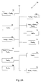
- a household 10 typically has a distributed mains wiring system consisting of one or more ring mains, several stubs and some distribution back to a junction box 12.
- the household 10 comprise four rooms 14, 16, 18 and 20. Every room 14-20 may have a different number of outlets and other mains connections.
- room 14 may have only one connection 22, room 16 may have two connections 24, 26, room 18 may have three connections 28, 30, 32 and room 20 may have six connections 34, 36, 38, 40, 42, 44.
- outlets in the household 10 there are a variety of distances and paths between different power outlets in the household 10.
- the outlets most closely located to each other are those on multi-plug strips, and the outlets furthest away from each other are those on the ends of stubs of different ring mains (e.g. power outlets in the garden shed and the attic).
- the majority of outlets associated with a particular application e.g. Home Cinema
- powerline will be used henceforth to refer to low voltage household mains distribution cabling (typically 100-240 V AC power) or any other distributed electrically conductive cabling (i.e. AC or DC), that is capable of passing power to appliances connected to it.
- powerline technology will be used henceforth to refer to a specification that when implemented as a series of network interface devices connected to a powerline, enables the devices to bi-directionally communicate with each other using signals superimposed on the power distribution signal already present on the powerline.
- network interface device will be used henceforth to describe an apparatus that implements either fully or partially, a communications technology, such as a powerline technology, to enable the apparatus to communicate with other devices connected to the same network (such as a powerline), regardless of whether or not the apparatus is integrated with other apparatuses or functions within a single enclosure.
- a device connected to a powerline network will be generically known henceforth as a “node”.
- the term “coverage” will henceforth be used to refer to the maximum distance between two nodes at which data transmitted therebetween is still detectable by either node.
- the term “throughput” will be understood to represent the rate at which nodes send or receive data on a network.
- wideband will be used henceforth to refer to a frequency band used by a powerline technology signal, characterised by having a bandwidth of greater than, or equal to, 10 MHz from the first frequency to the last frequency of the band irrespective of the presence of notches.
- narrowband will be used to refer to a frequency band used by a powerline technology signal, characterised by having a bandwidth of less than 10 MHz.
- transmission time will henceforth be used to describe the maximum amount of time it takes to transmit a single co-existent message.
- the transmission time includes, but is not limited to, a start of transmission marker time (if any), a synchronisation time (if any), a channel access resolution time (if any), a negotiation time (if any), a message transmission time, an acknowledge transmission time (if any) and an end of transmission marker time (if any).
- OFDM orthogonal frequency division multiplexing
- CDMA Code Division Multiple Access
- OFDM uses the sum of multiple overlapping but non-interfering, sub-carriers to carry content across a medium.
- OFDM is typically implemented using a discrete Fourier transform (DFT) (or its more specific fast Fourier transform (FFT)) as the filter bank at the core of the modulation block.
- DFT discrete Fourier transform
- FFT fast Fourier transform
- CDMA employs a code, rather than a frequency, as a carrier.
- the code is a pseudo-random sequence that can be purposely chosen for characteristics like frequency spectrum, orthogonality with other codes, etc. and can be considered as a more general case of a carrier than a single frequency.
- the codes may be mixed and recovered without losses after synchronisation.
- a further modulation technique known as Orthogonal Wavelet Division Multiplex (OWDM) was proposed by CEPCA and developed by Matsushita and employs a version of OFDM based on wavelet transforms.
- PLC In its early days, PLC was mainly used for home automation (e.g. remote control of lighting) using very low data transmission rates (i.e. ⁇ 1Mbps). However, in recent years several medium data-rate PLC technologies have been developed (including HomePlug 1.0 and other proprietary solutions) that enable data to be transmitted at tens of Megabits per second.
- the HomePlug 1.0 system is described in United States Patent No. US5574748 and the DS2 proprietary system is described in European Patent Application No. EP1351408 .
- Both the HomePlug AV standard and the OPERA standard use the frequency range of 1-30MHz to transmit signals and the developers of these standards have campaigned with regulators to allow signals within this frequency range to be transmitted at elevated power-levels.
- radio waves emitted from signals injected at these frequencies can interfere with licensed radio services (e.g. emergency services).
- regulators have required PLC operators to ensure that PLC technologies attenuate or "notch" PLC signals in frequency bands where licensed services are in nearby use.
- notch will be used henceforth to refer to a frequency band where the energy level of a powerline technology signal has been deliberately reduced to prevent interference with other users of the spectrum (whether on or off the powerline). Notches are characterized by having a narrower bandwidth than the powerline technology signal itself and are generally implemented by digital or analogue signal processing means within a single digital signal processing block or analogue front end.
- sub-band will be used henceforth to refer to a frequency band where a powerline technology signal characteristic differs from the characteristics of the powerline technology signal in the remainder of the signal's bandwidth. Such differences can include the optional or mandatory presence of the sub-band, the signal power level of the sub-band and the directionality of the sub-band.
- Sub-bands are characterized by having a narrower bandwidth than the powerline technology signal itself.
- the use of overlapping sub-bands in OFDM enables notches to be created, wherein a sub-band is disabled if the reception of the sub-band is heavily impaired or the sub-band can interfere with another service.
- OWDM can simplify the notching out of carriers due to its lower side lobes.
- the above-mentioned new PLC standards permit a node to have only one physical receiver and one transmitter active at any given time.
- High throughput is achieved in these systems by employing a large number of bits per second per hertz (i.e. bps/Hz) in their modulation schemes.
- bps/Hz bits per second per hertz
- Sharing the frequency spectrum within a communication band is less beneficial and more complex, because of overlaps between each of the current modulation technologies. This has a direct impact on the performance of each PLC standard in the absence of negotiation between user modems.
- a proposal to allow frequency band changes has been disclosed in International Patent Application No. WO2003015291 .
- both the frequency sharing approach (described in W020030152919 ) and the above-mentioned time sharing approaches are merely co-existence strategies, rather than communication technologies.
- the 45Mbps Mixed Analog-Digital Broadband IC for Internet Power-Line Data Synchronous Link (codename Madbric) has the ability to use different frequency bands for different applications.
- the different bands are all in the 1-30MHz range, and are used for either reception or transmission, effectively being part of the same communication system, and are not being capable of being operated independently.
- Patent No. TW516283 describes an apparatus comprising an analogue front-end that with minimal design change can work in two different frequency bands.
- the apparatus cannot operate in the two different frequency bands simultaneously (i.e. concurrently and reliably on the same powerline at any given instant in time).
- the purpose of the apparatus is to enable the same modem to be built for different frequency bands by changing a few components in the design. Once configured, the apparatus will only transmit in the configured frequency band (i.e. above or below 25MHz). In other words, once configured, only one frequency band will be available for communication.
- United States Patent No. US2004107588 describes an analogue front end for a PLC system that is capable of shifting a total and unique frequency band, using a mixer or a synthesizer (similar to a tuner in a radio) to translate a transmitted or received band from one frequency to another. This provides the ability to transmit and receive signals from any frequency band, but does not allow multiple bands to simultaneously and independently (i.e. without synchronisation of different operating phases such as reception, transmission, negotiation etc.) communicate with different parts of the network.
- United States Patent Application No. US2003016123 describes a power control system that injects more power into each of the sub-bands of an OFDM system that are more affected by channel impairments.
- the resulting signal is transmitted as a single band, but with a particular power shape depending on the sub-band power assignation.
- the power-shaping is performed within the same wideband signal, transmitting different power levels for each sub band.
- These sub-bands are part of the same communication system. As such, there is no independent and simultaneous operation. Consequently, there is no need to implement analogue separation of each of the sub-bands into different receiver or transmitter paths.
- United States Patent No. US5777544 describes a method of combining a narrowband control signal with a wideband data signal.
- the signals are not operated independently and are in fact synchronised. More particularly, one signal is purposefully a narrowband signal for control, the other signal is wideband in nature and used for general communication.
- analogue implementation cost also increase non-linearly with bps/Hz.
- an N bit converter is not simply twice the size of a N/2 bit converter, as there must either be a binary increase in the number of elements, or the elements must be made larger to achieve the matching performance expected of the higher quality converter.
- the bps/Hz requirement increases the linearity specifications of the interface circuitry so that the signal to noise and distortion (SINAD) ratio of the increased bps/Hz modulation scheme is achieved.
- SINAD signal to noise and distortion
- Prior art PLC systems only allow single technology broadband communication and employ a single analogue front-end that must cope with the entire dynamic range of a transmitted signal, even if in certain cases, the signal can be split into different frequency sub-bands by PLC modulation techniques, (e.g. creating notches with OFDM by disabling some of the carrier frequencies, or in the sub-band approach described in International Patent Application No. WO2004100392 ).
- PLC modulation techniques e.g. creating notches with OFDM by disabling some of the carrier frequencies, or in the sub-band approach described in International Patent Application No. WO2004100392 ).
- None of the prior-art solutions allow the possibility of a single integrated communication network which enables two or more wideband, general use, simultaneous and independent bi-directional broadband data communication technologies to work in the same powerline medium, to achieve a better cost/performance trade-off and expandability to Gbit/s performance levels.
- a device for communicating over a powerline comprising a means of substantially simultaneously sending and/or receiving data over a plurality of widebands.
- a method of communicating over a powerline comprising substantially simultaneously sending and/or receiving data over a plurality of widebands.
- a powerline communication network comprising at least one of the powerline communication devices of the first aspect.
- a method of communicating in the powerline communication network of the third aspect comprising the method of the second aspect.
- a system for communicating over a powerline comprising the device for communicating over a powerline as claimed in any of the preceding claims; a means of connecting to the powerline; and a means for transmitting data from the device to appropriate applications or transmitting data from the applications to the device.
- the powerline communication device improves the throughput/coverage/cost performance trade-off of a powerline network when compared with current-generation PLC networks, by spreading the transmission of data into a plurality of independent wideband frequency bands that can be operated simultaneously and independently.
- the powerline communication device also facilitates inter-operability by using one of the frequency bands to facilitate communication with nodes employing previous powerline technologies.
- the powerline communication device provides a way of creating a scalable implementation of a heterogeneous network where nodes of previous technologies work, without loss of performance, together with new-generation powerline technologies.
- the powerline communication device enables the use of frequencies above 30 MHz whilst maintaining compatibility with current worldwide EMC regulations and standards. This is achieved by using a signal of frequency less than 30 MHz (as currently used by the powerline standard and/or regulations) and at least one other signal of frequency greater than 30 MHz without compromising the performance of any of the signals due to interference.
- the result is a new PLC system that facilitates interoperability with a pre-existing powerline communication technology within a wideband (currently in the frequency range of 1MHz to 30MHz) and provides the ability to extend the system into new significantly higher frequency widebands (at frequencies between 30MHz and 1GHz) to improve the overall throughput of the resulting communication system while simplifying the implementation of any single given wideband.
- the powerline communication device comprises a network interface device that employs an analogue signal processing means to separate the paths of different wideband signals received from the powerline before converting them to their digital representation.
- the analogue signal processing means also separates the paths of different wideband signals to be transmitted on the powerline (after their conversion from their digital representation).
- the network interface device employs TDMA (time division multiple access) and/or FDMA (frequency division multiple access) as a scheme for enabling co-existence, synchronisation and/or bi-directional transmission.
- the analogue signal processing means is a purposefully designed block comprising discrete and/or integrated electronic components and the natural characteristics of the wiring and/or printed circuit board traces used to interconnect said components.
- the powerline communication device increases the number of components and signal paths in the network interface device, the powerline communication device provides greater potential for optimising and reducing the cost/complexity of each of the components and signal paths. This is particularly the case, when the powerline communication device is employed in a system that must:
- Each of the pre-existing and new-generation powerline technologies may implement different modulation schemes (e.g. OFDM, CDMA and/or OWDM), either alone or in combination).
- the powerline communication device can send data through any or all of the bands.
- the powerline communication device can distribute the data from a single source or mesh it together with data repeated from another node on the network.
- Each node on the powerline communication network is an apparatus that integrates:
- the powerline communication device uses a signal (in line with the current standards and injected power regulations) of frequency less than about 30 MHz and at least one other signal of frequency greater than 30 MHz without compromising the performance of any of the signals due to interference. This feature enables the powerline communication device to increase throughput whilst enabling interoperability with previous PLC technologies.
- a wideband frequency band used in the powerline communication device whose frequency of less than about 30 MHz will be known henceforth as a "low band”.
- a wideband frequency band(s) used in the powerline communication device whose frequency is greater than about 30 MHz will be known henceforth as "high band(s)”.
- the main advantage of using a low band is the possibility for higher coverage than that achievable with a high band, due to the greater injected power allowed by the regulations and the lower channel attenuation.
- the main advantage of using a high band is the higher throughput achievable due to the greater available bandwidth.
- the powerline communication device can exploit the natural topology of powerline networks in a home, wherein a group of related devices and sockets are typically clustered close to each other (e.g. plasma screen, DVD player and speakers in a living room) and other clusters of devices and sockets are clustered elsewhere (e.g. desktop printer, scanner and ADSL router in a home office).
- a group of related devices and sockets are typically clustered close to each other (e.g. plasma screen, DVD player and speakers in a living room) and other clusters of devices and sockets are clustered elsewhere (e.g. desktop printer, scanner and ADSL router in a home office).
- Such household topologies can benefit from the high throughput short-range coverage provided by the high band (which is simultaneously and independently available within each of the clusters) whilst the low band can be used to carry the majority of data communications between the clusters. It will also be appreciated that some nodes may benefit from communications on both bands.
- the parallel use of multiple widebands enables the use of different injected power levels, receiver sensitivities, transmission times, symbol lengths and modulation techniques to optimise the performance and cost of each wideband, leading to a better cost performance solution even though it is necessary to provide more than one analogue and digital front-end.
- Part of the implementation cost advantage arises from the ability to reduce the bps/Hz in each wideband, but still maintain throughput performance because of the additional bandwidth available. This effect non-linearly compensates for the cost of implementing more than one wideband communication technology.
- the reduced coverage of the high band(s) is offset by the parallel use of the low band (with its greater allowable injected power).
- the powerline communication device may be used to provide Gbit/s performance at a lower cost than current 200Mbps systems, by using lower bps/Hz modulation schemes (i.e. approximately 5 bps/Hz rather than 10 bps/Hz) over multiple widebands.
- lower bps/Hz modulation schemes i.e. approximately 5 bps/Hz rather than 10 bps/Hz
- a network interface device In order to practically implement the powerline communication device, a network interface device must employ analogue separation and include multiple analogue front-ends.
- the use of analogue frequency separation enables each wideband technology to operate independently, and has the following main advantages:
- the powerline communication device can also allow other network technologies to be layered independently on top of it, for example:
- the network interface device can combine and partition data communicated across different paths to maximise performance, coexistence and interoperability whilst minimizing system cost.
- the powerline communication device of the present invention will be referred to henceforth as an “improved powerline communication device”.
- the network interface device of the improved powerline communication device will be referred to henceforth as an “improved network interface device”.
- the powerline communication network comprising nodes that are improved communication devices will be known henceforth as an “improved powerline communication network”.
- the following description will provide a broad overview of the improved powerline communication device.
- the next section will use an exemplary heterogeneous powerline network to discuss different communication link configurations supported by the improved powerline communication network.
- the operation of the improved powerline communication device will next be described by referring to a one-packet communication mechanism (using the repeator principle) implemented on the previously-described exemplary heterogeneous powerline network.
- a one-packet communication mechanism using the repeator principle
- the specific heterogeneous network described in these sections is used for illustrative purposes only. In particular, the examples described in these sections should in no way be construed as limiting the improved powerline communication device.
- the next section will describe the hardware architecture of a modem in a improved network interface device. To demonstrate the advantages and possible configurations of the improved powerline communication device, the next section will compare the paths in prior art network interface devices and the improved network interface device.
- the preferred embodiment of the improved powerline communication network comprises a plurality of nodes of which some employ a network interface device that enables simultaneous and independent communication over two or more widebands, to similar multi-wideband nodes.
- the first wideband comprises frequencies of less than 30MHz, in line with the current standards and injected power levels (and will henceforth be known as a low band) and the other wideband(s) comprise frequencies of greater than 30MHz (and will henceforth be known as high band(s)).
- This enables powerline technologies to be optimised for each of the widebands, so that the trade-off between cost, coverage and throughput will be superior to that achieved by a purely mono-wideband approach.
- the modulation schemes for each technology used within the improved powerline communication network can be optimised for cost. For instance it may not be necessary to use a particularly high modulation density (bps/Hz) in the low band to enhance throughput because the low band can work in parallel with the inherently high throughput high band(s).
- bps/Hz modulation density
- the improved powerline communication network provides inter-operability with prior art powerline technologies by also supporting communication with mono-wideband nodes (that use one of the powerline technologies supported in the low band or high band(s) and communicate at frequencies in the low or high band(s).
- the improved network interface device may be part of an external modem apparatus or embedded within another apparatus (e.g. computer, TV etc.). However, regardless of the manner in which an improved network interface device is included within a node, the device remains physically connected to electrically conductive cabling (that passes AC or DC power) and is capable of transmitting digital data across the cabling using either or all of the low and high bands.
- low band signals may be transmitted with a power of approximately up to -50dBm/Hz whereas high band signals may only be transmitted with a power that causes emissions in this frequency band to be lower than -80dBm/Hz. Accordingly, signals in the low band may be transmitted with a power approximately one thousand times greater than signals in the high band. Consequently, if signals in both of these bands were to be transmitted simultaneously, without using some form of analogue frequency isolation, the dynamic range and voltage compliancy requirements of the high band signals would be significantly increased.
- the potential for interference or saturation of a lower power signal may be even more problematic.
- one of the bands is used to receive a line-attenuated signal whose power level is close to the noise on the powerline (i.e. - 150dBm)
- the other band is used to transmit a signal at its maximum allowable transmission power
- the isolation required to prevent the signals from the two bands from interfering with each other would be approximately 100dB.
- this is beyond the current state of the art analogue implementations and would have high implementation costs.
- the improved network interface device employs an analogue separation means to isolate the paths from the powerline connection to an apparatus; to data-converters for each wideband.
- One of the most efficient ways of providing this isolation is by high-pass filtering or band-pass filtering high band signals, whilst minimising out-of band signals in the low band (using high linearity components and possibly analogue low-pass smoothing or anti-aliasing).
- other analogue techniques e.g. echo-cancelling or resistive diplexers
- these other techniques would be difficult to implement in the frequency ranges of the improved powerline communication network.
- the term “transmitter signal path” will be used to refer to the path of a signal transmitted from an apparatus to the powerline.
- the term “receiver signal path” will be used to refer to the path of a signal received by an apparatus from a powerline.
- Signals in the high band and the low band can use the same or different modulation techniques (e.g. OFDM, CDMA and/or ODWM) or time division schemes to facilitate co-existence and/or bi-directional communication.
- the low band could employ a modulation scheme that is inter-operable with one of the existing powerline modem standards or proposals, whilst the high band is used for performance expansion.
- Data and/or control can be passed through one or both of the widebands simultaneously and via a plurality of nodes in the form of a repeater network.
- the improved powerline communication device may be implemented on one or more integrated circuits (whether dedicated to the modem function or as part of an application system on a chip), and in combination with the characteristics of passive components and interconnects.
- the implementation of the analogue filtering means to separate the low band and high band(s)) employs a combination of all the components in the different signal paths, whether passive or active, integrated or discrete.
- the widebands it is possible for the widebands:
- the improved powerline communication device it is also possible to expand the improved powerline communication device to communicate on more than two widebands. Similarly, it is also possible for the widebands to overlap slightly if required, and to be different in frequency ranges to those cited in the specific description.
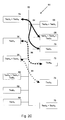
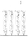
- a heterogeneous network 50 that represents the improved powerline communication network, comprises a plurality of nodes 54-76. Some of the nodes comprise the improved powerline communication device and accordingly implement more than one PLC technology. Nodes that do not include the improved network interface device can only implement one PLC technology. For the sake of simplicity, nodes that can only implement one PLC technology will be known henceforth as “mono-wideband nodes”. Similarly, nodes that can implement more than one technology will be known henceforth as "multi-wideband nodes”.
- Nodes 54 and 76 comprise the improved network interface device and are capable of implementing PLC technologies Tech A and Tech B .
- Nodes 58 and 66 comprise the improved network interface device and are capable of implementing PLC technologies Tech B and Tech C .
- nodes 60 and 68 comprise the improved network interface device and are capable of implementing all three PLC technologies.
- the remaining nodes do not comprise the improved network interface device and thus can only implement one of the PLC technologies.
- nodes 62 and 70 implement PLC technology Tech A only
- nodes 56 and 72 implement PLC technology Tech B only
- nodes 64 and 74 implement PLC technology Tech C only. All of the communication between the nodes on the network 50 takes place through a common powerline 52.
- One of the main advantages of the improved powerline communication network is that it supports communication between nodes that implement different PLC technologies.
- prior art PLC systems can only support communication between nodes that implement identical PLC technologies (e.g. nodes 56 and 72), even if the nodes in question co-exist on a network with nodes that implement other PLC technologies (e.g. nodes 64 and 74).
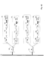
- Figure 2b shows two simultaneous, bi-directional and non-interfering communication links in the heterogeneous network 50 of Figure 2a.
- a first communication link 80 is a point-to-point communication link between nodes 54 and 68 which simultaneously uses the high band and low band to enable simultaneous communication of Tech A and Tech B messages between the two nodes.
- node 68 is capable of implementing all three technologies (i.e. Tech A , Tech B and Tech C ) only the Tech A and Tech B capabilities of node 68 are used in the first communication link 80. Furthermore, it should be noted that the first communication link 80 can redistribute data from the Tech A and Tech B technologies across the high band and the low band in accordance with the current network characteristics (e.g. channel impairments).
- a second communication link 82 connects nodes 68, 58, 60, 74 and 64. Since nodes 64 and 74 are only capable of implementing PLC technology Tech C , the second communication link 82 only supports communications of the Tech C technology. The presence of the two communication links 80 and 82 allows nodes 68, 58, 60, 74 and 64 to establish communication (through the second communication link 82) at the same time that node 68 is communicating with 56 (through the first communication link 80). In other words, the network arrangement depicted in Figure 2b, enables two simultaneous and concurrent communications to be performed, wherein the first communication link 80 enables dynamic data transmission and reception using technologies Tech A and/or Tech B and the second communication link 82 enables dynamic data transmission and reception using technology Tech C .
- Figure 2c shows three concurrent and simultaneous communication links 84, 86 and 88 in the heterogeneous network 50 of Figure 2a.
- the first communication link 84 provides a bi-directional point-to-multipoint connection between node 54 and nodes 68 and 70. Since node 70 is only capable of implementing technology Tech A , the first communication link only supports communications of the Tech A technology. Meanwhile a second communication link 86 enables communication between nodes 56 and 72 of technology Tech B with technology Tech A , using a co-existence strategy such as Time Division Multiple Access (TDMA) (i.e. a multiple access technique where only one transmitter transmits on a particular channel at any given time).
- TDMA Time Division Multiple Access
- a third communication link 88 supports communication of Tech C , wherein these communications are conducted in a different wideband that does not interfere with the other communication links.
- first communication link 90 between nodes 68, 58 and 60 of the heterogeneous network 50 depicted in Figure 2a.
- the first communication link 50 is bi-directional and supports communication of Tech B and Tech C .
- second communication link 92 between nodes 70 and 62 of the same heterogeneous network 50.
- the second communication link 92 supports communication of Tech A .
- Repeators can also be used to increase the coverage of a given technology (when a node can detect its neighbouring node, but not further nodes thereafter).
- a modem 80 in an improved network interface device comprises N blocks 82A-82N corresponding to each of the PLC technologies supported by the node.
- block 82A corresponds with the Tech A technology
- block 82B corresponds with the Tech B technology
- block 82N which corresponds with the Tech N technology.
- Each block 82A-82N comprises the first (PHY) and second (MAC) layers of the OSI stack for each technology.
- the block 82A comprises the blocks PHY A and MAC A .
- the block 82B comprises the blocks PHY B and MAC B .
- the modem 80 further comprises a data distribution block 84, which distributes data amongst the blocks 80A and 80N in accordance with the technology of the signal and current network traffic characteristics.
- signals from each technology supported by a node are processed by an analogue filter bank (not shown). The operation of the analogue filter bank will be described in more detail later.
- the processed signals 86 are forwarded to the data distribution block 84 for distribution amongst the blocks 82A-82N.
- the outputs from all of the blocks 82A-82N are combined in a coupling/decoupling stage 88 from which they are injected into a powerline 90.
- the coupling/decoupling stage 88 When used for receiving a signal from the powerline 90, the coupling/decoupling stage 88 decouples the component signals for each supported PLC technology. The decoupled signals are processed through blocks 82A-82N and forwarded through the data distribution block 84 to the appropriate applications running on the node.
- Each of the PHY blocks may have a feedback signal 92A-92N which provides information regarding the usage of each of the technology signal paths. This information is used by the data distribution block 84 to redistribute the data flow amongst the N available blocks 82A-82N. It should also be noted that parts of the MAC and PHY blocks (PHY A -PHY N ) and (MAC A -MAC N ) may be capable of sharing resources.
- a powerline 100 is connected to a single coupling unit 102, which has high-pass transmission characteristics to enable the rejection of the AC line frequency of the powerline 100.
- the coupling unit 102 is in turn connected to receiver and transmitter paths 104, 106, which are isolated during half duplex phases using an RX/TX switch 108.
- the receiver path 104 typically comprises a band-limiting anti-aliasing filter 110, a programmable gain amplifier (PGA) 112, and an ADC 114.
- the resulting digital signal 116 is then demodulated 118.
- the anti-aliasing filter 110 may be in a different order and may be partially or completely provided by the bandwidth of the PGA.
- the transmitter path 106 typically comprises a line driver 120 (which may or may not be capable of operating in high impedance mode) and a band-limiting smoothing filter 122.
- the band-limiting smoothing filter 122 limits the power of harmonics (in the out-of-band range) in the analogue signal (the harmonics being produced by the operation of a DAC 124 on a received digital signal 126 that had previously been modulated 128). It will be realised that part of the modulation and demodulation schemes 118, 128 could also be performed in the analogue domain.
- a slightly different form of a prior art single wideband system employs separate transmitter and receiver coupling units 130, 132.
- a TX/RX switch is not required in this form of the prior art powerline transmission system, as either the impedance of the line driver 120 does not significantly represent an extra impedance load to the powerline 100 or the line driver 120 itself is capable of going into a high impedance mode.
- the improved network interface device comprises two analogue front-ends separated into two low band analogue paths LB 1 and LB 2 and two high band paths HB 1 and HB 2 , by coupling units 140, 142, 144 and 146 respectively.
- the analogue filtering characteristics of the different paths are designed to pass the signal of a given band whilst rejecting the signals of the other bands.
- the modulation schemes of each technology 152, 154 may be the same or different, as may be the demodulation schemes 148, 150.
- coupling unit 166 is used for low band communication and coupling unit 176 is used for high band communication.
- the coupling units 166, 176 can be optimised to have different pass-frequency characteristics.
- each high band path (188-191 and 203-206) is isolated from the low band paths (192-195 and 197-201) by deliberately inserted filters 187, 202 with high pass or band pass characteristics.
- Figure 4f shows a fourth embodiment of the improved network interface device, applied to two different wideband technologies as in Figure 4e. Whilst there are many possible other combinations, it is important to note that it is not necessary for there to be separate paths and converters for the high band paths and low band paths in either the receiver or transmitter, as communications in one direction may benefit more from the improved network interface device than communications in the other direction.
- the improved network interface device comprises one coupling unit for transmission 218 and one for reception 208.
- the high band is isolated from the low-band on the receiver path, by deliberately inserted filters 209 with high-pass or band-pass characteristics.
- the transmitter modulation schemes are combined in the digital domain 222A, 222B and then passed through a very high performance DAC 221, smoothing filter 220 and line driver 219.
- the fourth embodiment is in theory a possible alternative, in reality it would probably be too expensive and technically challenging to implement with the bands and bps/Hz expected of a performing powerline network.
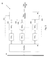
- an exemplary integrated circuit 250 implementation of the improved network interface device comprises two analogue front ends AFE A , AFE B for the two widebands of the improved powerline communication device.
- the exemplary integrated circuit 250 also comprises a logic element 226 to implement the different powerline modem technologies (including DFE and MAC) and provide a digital interface to the next stage application 228 in the device.
- the high band analogue front end (AFE B ) contains high band converters 230, 232 and active interface electronics (i.e. a PGA 234 and line driver 236) and connects to the powerline via a coupling unit along path 238.
- the low band analogue front end (AFE A ) comprises low band converters 240, 242 and active interface electronics (i.e. a PGA 244 and line driver 246) and connects to the powerline via a coupling unit along path 248.
- a digital representation of the signal to be sent on the low band and high band is produced in the logic element 226 and is present at interfaces 250, 252 to the analogue front ends AFE A , AFE B .
- an alternative integration partition 300 of the integrated circuit implementation of the improved network interface device there are two integrated circuits, namely a digital modem integrated circuit 302 and an analogue modem integrated circuit 304 containing the two analogue front ends AFE A , AFE B .
- the analogue front end of each wideband is split into data converters Conv A , Conv B and interface circuits I/Face A , I/Face B .
- the converters Conv A , Conv B are integrated with the digital logic 401 of the powerline modem in one integrated circuit 402 while the higher current/voltage interface circuitry is provided in another integrated circuit 404.
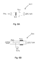
- a coupling unit can have frequency characteristics.
- a capacitive coupling unit 500 comprises X1 type capacitors 502 that are used to couple a signal source 504 (via an isolating transformer 506) onto a powerline 508.
- the impedances of the transformer 506, capacitors 502, signal source 504 and the powerline 508 determine the frequency response of the capacitive coupling unit 500.
- an inductive coupling unit 520 comprises a signal transformer 522 that inductively couples a signal 524 in tandem with a Y1 type capacitor 526.
- the inductive coupling unit 520 is roughly equivalent to the capacitive coupling unit 500 (depicted in Figure 6a), with the respective impedances of the transformer 522, capacitor 526, signal source 524 and powerline 528 determining the frequency response of the inductive coupling unit 520.
- a low-pass filtered version of the powerline 508, 528 can be used within the improved network interface device to provide a power supply. It is also possible to implement higher order filters in the coupling units with more passive components. Nonetheless, it will be appreciated that it is possible to employ many other types of coupling unit (e.g. optical coupling units) in the powerline network interface device.
- coupling unit e.g. optical coupling units
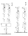
- Figures 7a to 7c illustrates the exemplary frequency spectra of a number of different powerline technologies, and demonstrates how an analogue filtering means could be used to separate the signals of a given technology (from the signals of the other technologies) into a particular signal path.
- a first technology Tech A has a transmission power P A and a wide-band 540 delimited by frequencies f A1 and f A2 .
- the wide-band 540 has internal notches 542 to comply with EMC regulations.
- a second technology Tech B has a transmission power of P B and a wide-band 544 delimited by frequencies f B1 and f B2 .
- the wide-band 544 also has a notch 546 to comply with EMC regulations. It should be noted that f B1 must be greater than f A2 to avoid band-overlapping.
- a third technology Tech N has transmission power P N and a wide-band 548 delimited by frequencies f N1 and f N2 .
- the wide-band 548 also has a notch 550 to comply with regulations.
- the minimum wide-band frequency supported by the powerline technologies communicated by the powerline network system is 10 MHz.
- a first, second and third analogue filter respectively isolate the signals from each of Tech A , Tech B and Tech N , from the signals from the other technologies.
- the analogue filter characteristics are applicable to the transmitter and/or the receiver of each technology within a node.
- the first analogue filter Filt A is defined by passband start and end frequencies f A3 , f A4 .
- the second analogue filter Filt B is defined by passband start and end frequencies f B3 and f B4 .
- the third analogue filter Filt N is defined by passband start and end frequencies f N3 and f N4 .
- the start of at least one of the passbands of the analogue separating means of the powerline communication device is between 1 MHz and 30MHz, and is at least 10MHz in width. At least one of the other bands exists at a frequency greater than 30MHz and less than 1 GHz.
- the difference between the passband and stopband for any one of the elements of the analogue separating means is more than 6dB.
- analogue filters it is possible for different analogue filters to overlap (e.g. f A4 >f B3 ), or not to overlap (e.g. f B4 ⁇ f N3 ). It should also be noted that it is not necessary for the passbands of all of the analogue filters to have the same transmission power.
- the product of the analogue filter characteristic and the modulation scheme of a given PLC technology determines the effectiveness of the isolation by each analogue filter.
- the absolute transmission of the filters in their respective passbands is less important than the ratio of passband to stopband, as any attenuation differences in these filters can often be compensated for with more injected power at the pre-filter stage and/or increased receiver sensitivity.
- Figure 7c shows an example of the isolation provided by the second analogue filter Filt B to the Tech B signal.
- the second analogue filter passes a signal Path B that is the product of the transmission power (PF B ) of then passband of the second analogue filter and the transmission power (P B ) of the Tech B signal.
- the signals of the other technologies (Tech A and Tech N ) are attenuated by the stopband of Filt B to a power level PF N that is sufficiently less than PF B to ensure that they do not significantly interfere with the Path B signal.
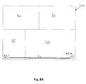
- One of the important advantages of the multi-wideband concept implemented in the improved powerline communication network is the ability to provide increased throughput as the number of nodes increase in the network.
- increased throughput demand typically coincides with an increased number of nodes, since more data needs to be transmitted when multiple devices share the network.
- Figure 8a shows a simple initial installation of a single service, in this case IPTV delivered to the home 600 (depicted in Figure 1) via a DSL connection 602, which is distributed (using the improved powerline communication network) from the DSL modem 602 in the office to a TV set 604 in the living room. Since the distance between the DSL modem 602 and the TV set 604 is comparatively long, the connection C1 therebetween predominantly uses the low band due to its inherently greater coverage. The bandwidth provided by the low band is sufficient for the TV set because only a single TV channel is transmitted.
- connections C2-C7 are predominantly implemented using the high band (due to its greater throughput) over the relatively short distances present.
- Low band connections C8, C9 will still be in use when their efficiency is higher than using multiple hops of high band links.
- many connections e.g. C10 will be served by communication using both bands.
- a node on the network will typically discover the other nodes on the powerline through some form of synchronisation that is usually defined within the powerline technology used in one of the bands.
- the node will also identify the technology capabilities and virtual network membership of the detected nodes, to determine what communication will be possible and/or allowable (for instance, whilst a detected node may physically have certain technology capabilities, these may be impaired by interference or restricted in use).
- the sending node Having identified the physically possible and allowable communications, the sending node will decide the best path for sending/receiving data, based on factors such as the type of data to be communicated, how it is ranked in the QoS and the available channel capacity.
Priority Applications (18)
| Application Number | Priority Date | Filing Date | Title |
|---|---|---|---|
| EP05256179.2A EP1770870B1 (de) | 2005-10-03 | 2005-10-03 | Verfahren und Vorrichtung zur Stromleitungskommunikation |
| US11/467,141 US7899436B2 (en) | 2005-10-03 | 2006-08-24 | Multi-wideband communications over power lines |
| US11/536,539 US20070076666A1 (en) | 2005-10-03 | 2006-09-28 | Multi-Wideband Communications over Power Lines |
| EP06794617.8A EP1932249B1 (de) | 2005-10-03 | 2006-10-02 | Mehr-breitband-kommunikation auf stromleitungen |
| JP2008532879A JP2009510867A (ja) | 2005-10-03 | 2006-10-02 | 電力線を通じての複数の広帯域による通信 |
| PCT/GB2006/003665 WO2007039723A1 (en) | 2005-10-03 | 2006-10-02 | Multi-wideband communications over power lines |
| CNA2006800365841A CN101292437A (zh) | 2005-10-03 | 2006-10-02 | 电力线上的多宽带通信 |
| US11/752,865 US8213895B2 (en) | 2005-10-03 | 2007-05-23 | Multi-wideband communications over multiple mediums within a network |
| US11/752,887 US8406239B2 (en) | 2005-10-03 | 2007-05-23 | Multi-wideband communications over multiple mediums |
| US12/484,754 US7877078B2 (en) | 2005-10-03 | 2009-06-15 | Power line communication networks and methods employing multiple widebands |
| US12/554,400 US7725096B2 (en) | 2005-10-03 | 2009-09-04 | Multi-wideband communications over power lines |
| US12/770,586 US7970374B2 (en) | 2005-10-03 | 2010-04-29 | Multi-wideband communications over power lines |
| US12/972,302 US20110205918A1 (en) | 2005-10-03 | 2010-12-17 | Apparatus for Power Line and Wireless Communications |
| US12/986,945 US20120014459A1 (en) | 2005-10-03 | 2011-01-07 | Power Line Communication Networks and Methods employing Multiple Widebands |
| US13/036,870 US8538369B2 (en) | 2005-10-03 | 2011-02-28 | Multi-wideband communications over power lines |
| US13/163,376 US8204472B2 (en) | 2005-10-03 | 2011-06-17 | Multi-wideband communications over power lines |
| US13/485,133 US20120243621A1 (en) | 2005-10-03 | 2012-05-31 | Multi-Wideband Communications over Multiple Mediums within a Network |
| US13/781,105 US9036649B2 (en) | 2005-10-03 | 2013-02-28 | Multi-wideband communications over multiple mediums |
Applications Claiming Priority (1)
| Application Number | Priority Date | Filing Date | Title |
|---|---|---|---|
| EP05256179.2A EP1770870B1 (de) | 2005-10-03 | 2005-10-03 | Verfahren und Vorrichtung zur Stromleitungskommunikation |
Publications (2)
| Publication Number | Publication Date |
|---|---|
| EP1770870A1 true EP1770870A1 (de) | 2007-04-04 |
| EP1770870B1 EP1770870B1 (de) | 2019-04-03 |
Family
ID=35456000
Family Applications (1)
| Application Number | Title | Priority Date | Filing Date |
|---|---|---|---|
| EP05256179.2A Active EP1770870B1 (de) | 2005-10-03 | 2005-10-03 | Verfahren und Vorrichtung zur Stromleitungskommunikation |
Country Status (3)
| Country | Link |
|---|---|
| US (5) | US7899436B2 (de) |
| EP (1) | EP1770870B1 (de) |
| CN (1) | CN101292437A (de) |
Cited By (11)
| Publication number | Priority date | Publication date | Assignee | Title |
|---|---|---|---|---|
| WO2009150224A1 (en) * | 2008-06-13 | 2009-12-17 | Gigle Semiconductors Limited | Power line communication system |
| WO2010010216A1 (es) * | 2008-07-14 | 2010-01-28 | Diseño De Sistemas En Silicio, S.A. | Procedimiento de transmisión de datos multibanda |
| EP2400667A1 (de) * | 2010-06-23 | 2011-12-28 | Gigle Networks Limited | Kommunikationsnetz und Verfahren dafür |
| CN103973338A (zh) * | 2013-02-04 | 2014-08-06 | 刘锦文 | 电力线载波控制模块 |
| CN103973520A (zh) * | 2013-01-24 | 2014-08-06 | 上海芯域微电子有限公司 | 电力线载波多媒介高速宽带互联终端装置 |
| CN105049084A (zh) * | 2015-08-06 | 2015-11-11 | 珠海慧信微电子有限公司 | 电力线载波通信组网方法、装置和系统 |
| CN106209676A (zh) * | 2016-06-30 | 2016-12-07 | 广东睿江云计算股份有限公司 | 基于多设备的云主机系统的数据处理方法及装置 |
| US10002995B2 (en) | 2013-09-09 | 2018-06-19 | Marvell World Trade Ltd. | Multiple transmission windows for OFDM symbol |
| US10141984B2 (en) | 2008-07-14 | 2018-11-27 | Marvell World Trade Ltd. | Multi-band transmission system |
| CN109643478A (zh) * | 2016-07-22 | 2019-04-16 | 亚马逊技术有限公司 | 用于无线音频/视频记录和通信装置的无线扬声器装置 |
| WO2021148398A1 (en) | 2020-01-20 | 2021-07-29 | Basf Se | Evaporation retardant membrane for odorant compositions |
Families Citing this family (39)
| Publication number | Priority date | Publication date | Assignee | Title |
|---|---|---|---|---|
| US20080159358A1 (en) * | 2007-01-02 | 2008-07-03 | David Ruiz | Unknown Destination Traffic Repetition |
| US20110205918A1 (en) * | 2005-10-03 | 2011-08-25 | Hurwitz Jonathan E D | Apparatus for Power Line and Wireless Communications |
| EP1770870B1 (de) * | 2005-10-03 | 2019-04-03 | Avago Technologies International Sales Pte. Limited | Verfahren und Vorrichtung zur Stromleitungskommunikation |
| US8406239B2 (en) * | 2005-10-03 | 2013-03-26 | Broadcom Corporation | Multi-wideband communications over multiple mediums |
| US7970374B2 (en) * | 2005-10-03 | 2011-06-28 | Broadcom Corporation | Multi-wideband communications over power lines |
| US8213895B2 (en) | 2005-10-03 | 2012-07-03 | Broadcom Europe Limited | Multi-wideband communications over multiple mediums within a network |
| US7808985B2 (en) * | 2006-11-21 | 2010-10-05 | Gigle Networks Sl | Network repeater |
| FR2891968B1 (fr) * | 2005-10-12 | 2008-01-18 | Valeo Electronique Sys Liaison | Systeme de communication entre une unite d'acquisition d'images video et un ordinateur de bord pour un vehicule automobile |
| US8520715B2 (en) * | 2006-07-06 | 2013-08-27 | Broadcom Corporation | Adaptative multi-carrier code division multiple access |
| US7860146B2 (en) * | 2006-07-06 | 2010-12-28 | Gigle Networks, Inc. | Adaptative multi-carrier code division multiple access |
| US8213582B2 (en) * | 2008-03-14 | 2012-07-03 | Broadcom Europe Limited | Coupling signal processing circuitry with a wireline communications medium |
| US9705562B2 (en) * | 2006-07-25 | 2017-07-11 | Broadcom Europe Limited | Dual transformer communication interface |
| US8885814B2 (en) * | 2006-07-25 | 2014-11-11 | Broadcom Europe Limited | Feedback impedance control for driving a signal |
| US8094643B2 (en) * | 2008-07-10 | 2012-01-10 | Qualcomm Incorporated | Dynamic power management for time division multiplexing devices |
| US8212944B2 (en) * | 2008-07-10 | 2012-07-03 | Qualcomm Incorporated | Fast stream switching |
| US8674823B1 (en) | 2009-05-12 | 2014-03-18 | Plug ID, LLC. | Power management system |
| US8675651B2 (en) * | 2010-01-18 | 2014-03-18 | Qualcomm Incorporated | Coexistence mechanism for non-compatible powerline communication devices |
| US8718115B2 (en) * | 2010-10-08 | 2014-05-06 | Texas Instruments Incorporated | Building, transmitting, and receiving frame structures in power line communications |
| JP5172938B2 (ja) * | 2010-12-14 | 2013-03-27 | 本田技研工業株式会社 | 車両用電力線通信装置 |
| FR2970828A1 (fr) * | 2011-01-25 | 2012-07-27 | France Telecom | Filtre de ponderation, procedes et dispositifs d'emission et de reception d'un signal analogique et programme d'ordinateur correspondants |
| US9300491B2 (en) | 2011-02-11 | 2016-03-29 | Qualcomm Incorporated | Frame delivery path selection in hybrid communication networks |
| US8897169B2 (en) | 2011-03-02 | 2014-11-25 | Qualcomm Incorporated | Discovery of conventional devices and bridges in hybrid communication networks |
| US9025603B2 (en) | 2011-03-08 | 2015-05-05 | Qualcomm Incorporated | Addressing scheme for hybrid communication networks |
| WO2012125743A1 (en) | 2011-03-14 | 2012-09-20 | Qualcomm Atheros, Inc. | Hybrid networking simple-connect setup via proxy device |
| EP2686997B1 (de) * | 2011-03-14 | 2018-10-10 | Qualcomm Incorporated | Master-kennwortsatz für hybridvernetzung |
| US20130002409A1 (en) * | 2011-06-30 | 2013-01-03 | Broadcom Corporation | Powerline communication device with adaptable interface |
| US8483291B2 (en) * | 2011-06-30 | 2013-07-09 | Broadcom Corporation | Analog to digital converter with increased sub-range resolution |
| JP5915015B2 (ja) | 2011-07-25 | 2016-05-11 | ソニー株式会社 | 通信装置及び通信方法、並びに通信システム |
| US9059932B2 (en) | 2011-11-03 | 2015-06-16 | Qualcomm Incorporated | Packet ordering based on delivery route changes in communication networks |
| US8824477B2 (en) | 2011-11-03 | 2014-09-02 | Qualcomm Incorporated | Multiple delivery route packet ordering |
| TW201328205A (zh) * | 2011-12-23 | 2013-07-01 | Hon Hai Prec Ind Co Ltd | 音頻設備轉接器 |
| TW201327170A (zh) * | 2011-12-23 | 2013-07-01 | Hon Hai Prec Ind Co Ltd | Ieee1394設備轉接器 |
| US9490887B2 (en) | 2013-03-28 | 2016-11-08 | Sony Corporation | Communication device and method providing beamforming for two or more transmission channels |
| US9529763B2 (en) | 2013-07-02 | 2016-12-27 | Infineon Technologies Ag | Sensor systems and methods utilizing adaptively selected carrier frequencies |
| CN103414496A (zh) * | 2013-08-02 | 2013-11-27 | 华为技术有限公司 | 电力线通信方法、集中控制装置和终端、电力线通信系统 |
| US9571315B2 (en) | 2013-09-10 | 2017-02-14 | Infineon Technologies Ag | Sensor systems and methods utilizing band pass filter tuning |
| CN105900345B (zh) * | 2014-12-04 | 2019-04-19 | 华为技术有限公司 | 一种信号处理电路 |
| CN106936473B (zh) * | 2015-12-30 | 2020-02-14 | 杭州华为数字技术有限公司 | 电力线通信节点分组的方法和相关设备 |
| CN114598355B (zh) * | 2022-02-10 | 2023-05-23 | 珠海格力电器股份有限公司 | 载波通信系统 |
Citations (4)
| Publication number | Priority date | Publication date | Assignee | Title |
|---|---|---|---|---|
| EP0580457A1 (de) | 1992-05-27 | 1994-01-26 | Denis Albert Koubi | Verfahren und Einrichtung zur Übertragung von Information und breitbandigen analogen und/oder digitalen Signalen durch Benutzung der elektrischen Energieversorgungsnetzes |
| EP1134909A1 (de) | 2000-03-14 | 2001-09-19 | Biwave Technologies | Einzelkabelübertragungsvorrichtung für Signale und Stromversorgung eines Überwachungssystems |
| EP1432138A1 (de) | 2002-12-19 | 2004-06-23 | Laboratoire Europeen ADSL | Vorrichtung und Verfahren zur Verteilung von digitalen Daten |
| WO2004100392A1 (fr) | 2003-04-30 | 2004-11-18 | Spidcom Technologies | Procede de transmission de donnees par courant porteur |
Family Cites Families (126)
| Publication number | Priority date | Publication date | Assignee | Title |
|---|---|---|---|---|
| US3445763A (en) | 1965-10-06 | 1969-05-20 | Gen Electric | Digital reading impedance measuring arrangement |
| US3379973A (en) | 1966-01-10 | 1968-04-23 | Halliburton Co | Impedance measuring circuit having the unknown impedance in the feedback path of an amplifier |
| US4096361A (en) | 1977-06-20 | 1978-06-20 | Bell Telephone Laboratories, Incorporated | Test apparatus for obtaining impedance settings for hybrid balance networks |
| US4224483A (en) | 1979-03-12 | 1980-09-23 | Bell Telephone Laboratories, Incorporated | Electronic loaded/nonloaded telephone loop identification circuit |
| CA1158738A (en) | 1980-04-30 | 1983-12-13 | Manitoba Telephone System (The) | Video and data distribution module with subscriber terminal |
| US4636711A (en) | 1984-12-04 | 1987-01-13 | Airborne Electronics, Inc. | Pulse width modulation control circuit with a variable zero to one hundred percent duty cycle |
| US4636771A (en) | 1984-12-10 | 1987-01-13 | Westinghouse Electric Corp. | Power line communications terminal and interface circuit associated therewith |
| US4922534A (en) | 1985-11-18 | 1990-05-01 | General Datacomm, Inc. | Intelligent synchronous modem and communication system incorporating the same |
| US4772870A (en) | 1986-11-20 | 1988-09-20 | Reyes Ronald R | Power line communication system |
| US6104707A (en) | 1989-04-28 | 2000-08-15 | Videocom, Inc. | Transformer coupler for communication over various lines |
| US5929896A (en) | 1989-07-14 | 1999-07-27 | Inline Connection Corporation | RF broadcast system utilizing internal telephone lines |
| US5090024A (en) | 1989-08-23 | 1992-02-18 | Intellon Corporation | Spread spectrum communications system for networks |
| US6014386A (en) | 1989-10-30 | 2000-01-11 | Videocom, Inc. | System and method for high speed communication of video, voice and error-free data over in-wall wiring |
| IL100127A0 (en) | 1991-03-11 | 1992-08-18 | Future Domain Corp | Scsi controller |
| US5287065A (en) | 1991-10-04 | 1994-02-15 | Doble Engineering Company | Automatic bridge balancing using controllable impedance in characterizing unknown impedance |
| GB9222205D0 (en) | 1992-10-22 | 1992-12-02 | Norweb Plc | Low voltage filter |
| US5880631A (en) | 1996-02-28 | 1999-03-09 | Qualcomm Incorporated | High dynamic range variable gain amplifier |
| US6697415B1 (en) | 1996-06-03 | 2004-02-24 | Broadcom Corporation | Spread spectrum transceiver module utilizing multiple mode transmission |
| US6893868B2 (en) * | 1997-02-20 | 2005-05-17 | Onco Immunin, Inc. | Homo-doubly labeled compositions for the detection of enzyme activity in biological samples |
| US5777544A (en) | 1997-03-17 | 1998-07-07 | Intellon Corporation | Apparatus and method for controlling data communications having combination of wide and narrow band frequency protocols |
| US5978371A (en) | 1997-03-31 | 1999-11-02 | Abb Power T&D Company Inc. | Communications module base repeater |
| JP3171141B2 (ja) | 1997-06-06 | 2001-05-28 | 日本電気株式会社 | 移動体通信用送信機およびその制御方法 |
| US6243413B1 (en) | 1998-04-03 | 2001-06-05 | International Business Machines Corporation | Modular home-networking communication system and method using disparate communication channels |
| US6353628B1 (en) | 1998-12-15 | 2002-03-05 | Nortel Networks Limited | Apparatus, method and system having reduced power consumption in a multi-carrier wireline environment |
| EP1104101A3 (de) * | 1999-11-26 | 2005-02-02 | Matsushita Electric Industrial Co., Ltd. | Vorrichtung zur Teilbandtrennung / Zusammensetzung eines digitalen Signal zur erzeugung einer Filterung mit Bandtrennung und Bandzusammensetzung mit verringerten Gruppenlaufzeit |
| DE10014676C2 (de) | 2000-03-24 | 2002-02-07 | Polytrax Inf Technology Ag | Datenübertragung über ein Stromversorgungsnetz |
| US7054279B2 (en) | 2000-04-07 | 2006-05-30 | Broadcom Corporation | Method and apparatus for optimizing signal transformation in a frame-based communications network |
| US6998962B2 (en) | 2000-04-14 | 2006-02-14 | Current Technologies, Llc | Power line communication apparatus and method of using the same |
| US7103240B2 (en) | 2001-02-14 | 2006-09-05 | Current Technologies, Llc | Method and apparatus for providing inductive coupling and decoupling of high-frequency, high-bandwidth data signals directly on and off of a high voltage power line |
| US6965302B2 (en) | 2000-04-14 | 2005-11-15 | Current Technologies, Llc | Power line communication system and method of using the same |
| US20020110311A1 (en) | 2001-02-14 | 2002-08-15 | Kline Paul A. | Apparatus and method for providing a power line communication device for safe transmission of high-frequency, high-bandwidth signals over existing power distribution lines |
| US7079537B1 (en) | 2000-04-25 | 2006-07-18 | Advanced Micro Devices, Inc. | Layer 3 switching logic architecture in an integrated network switch |
| WO2001095518A2 (en) | 2000-06-07 | 2001-12-13 | Conexant Systems, Inc. | Method and apparatus for dual-band modulation in powerline communication network systems |
| KR100348625B1 (ko) | 2000-06-16 | 2002-08-13 | 엘지전자 주식회사 | 네트워크 인프라 통합 시스템 |
| US6518839B2 (en) | 2000-06-28 | 2003-02-11 | Texas Instrumetns Incorporated | Method and apparatus for effecting programmable gain amplification |
| DE10031538C2 (de) | 2000-06-28 | 2002-12-12 | Siemens Ag | Digital/Analog-Wandler |
| US20040213237A1 (en) | 2000-06-29 | 2004-10-28 | Toshikazu Yasue | Network authentication apparatus and network authentication system |
| DE10038372C2 (de) | 2000-08-07 | 2003-03-13 | Infineon Technologies Ag | Differentieller Digital/Analog-Wandler |
| US7248148B2 (en) | 2000-08-09 | 2007-07-24 | Current Technologies, Llc | Power line coupling device and method of using the same |
| EP1323288A4 (de) | 2000-08-14 | 2007-03-21 | Main Net Comm Ltd | Stromleitungs-kommunikationssystem |
| US6411163B1 (en) | 2000-08-14 | 2002-06-25 | Intersil Americas Inc. | Transconductance amplifier circuit |
| JP4520032B2 (ja) | 2000-08-17 | 2010-08-04 | パナソニック株式会社 | ヘッダ圧縮装置およびヘッダ圧縮方法 |
| WO2002017100A1 (en) | 2000-08-24 | 2002-02-28 | 2Wire, Inc. | System and method for selectively bridging and routing data packets between multiple networks |
| JP2002077251A (ja) | 2000-08-28 | 2002-03-15 | Nec Corp | データ伝送システム、データ中継装置、およびデータ中継方法 |
| US6373377B1 (en) | 2000-10-05 | 2002-04-16 | Conexant Systems, Inc. | Power supply with digital data coupling for power-line networking |
| ES2184587B1 (es) | 2000-12-18 | 2004-08-01 | Diseño De Sistemas En Silicio, S.A. | Sistema y procedimiento de transmision digital de datos punto a multipunto sobre red electrica. |
| DE10063675C1 (de) | 2000-12-20 | 2002-06-20 | Siemens Ag | Verfahren und Vorrichtung zur Übertragung von Daten auf wenigstens einer elektrischen Energieversorgungsleitung |
| EP1371219A4 (de) | 2001-02-14 | 2006-06-21 | Current Tech Llc | Datenkommunikation über eine stromversorgungsleitung |
| ES2186531B1 (es) | 2001-04-19 | 2005-03-16 | Diseño De Sistemas En Silicio, S.A. | Procedimiento de acceso multiple y multiple transmision de datos para un sistema multiusuario de transmision digital de datos punto a multipunto sobre red electrica. |
| EP1253736A3 (de) | 2001-04-26 | 2003-12-10 | NTT DoCoMo, Inc. | Datenübertragungsstreckensteuerung für mobile Kommunikation |
| US8296817B2 (en) | 2001-05-17 | 2012-10-23 | Broadcom Corporation | Apparatus for transporting home networking frame-based communications signals over coaxial cables |
| US7245472B2 (en) | 2001-05-18 | 2007-07-17 | Curretn Grid, Llc | Medium voltage signal coupling structure for last leg power grid high-speed data network |
| US7173935B2 (en) | 2002-06-07 | 2007-02-06 | Current Grid, Llc | Last leg utility grid high-speed data communication network having virtual local area network functionality |
| WO2002101952A1 (en) | 2001-06-12 | 2002-12-19 | Main.Net Communications Ltd. | Coupling circuits for power line communications |
| WO2003009083A2 (en) | 2001-07-17 | 2003-01-30 | Main.Net Communications Ltd. | Dual purpose power line modem |
| WO2003015291A2 (en) | 2001-08-04 | 2003-02-20 | Enikia Llc | Frequency management and policing |
| WO2004014056A1 (en) | 2001-08-04 | 2004-02-12 | Enikia Llc | Power line communication system |
| US20030062990A1 (en) | 2001-08-30 | 2003-04-03 | Schaeffer Donald Joseph | Powerline bridge apparatus |
| US6947736B2 (en) | 2001-11-20 | 2005-09-20 | Texas Instruments Incorporated | Universal broadband home network for scalable IEEE 802.11 based wireless and wireline networking |
| JP4075461B2 (ja) | 2001-11-27 | 2008-04-16 | ソニー株式会社 | 通信システム、通信端末及び通信方法 |
| US7053756B2 (en) | 2001-12-21 | 2006-05-30 | Current Technologies, Llc | Facilitating communication of data signals on electric power systems |
| ATE329415T1 (de) | 2002-03-12 | 2006-06-15 | Koninkl Philips Electronics Nv | Repeater für versorgungsleitungssystem |
| US6847678B2 (en) | 2002-04-25 | 2005-01-25 | Raytheon Company | Adaptive air interface waveform |
| US6957086B2 (en) * | 2002-05-01 | 2005-10-18 | Microsoft Corporation | Method for wireless capability discovery and protocol negotiation, and wireless device including same |
| US7113763B2 (en) * | 2002-06-03 | 2006-09-26 | Nokia Corporation | Bluetooth access point and remote bluetooth modules for powerline based networking |
| US7027483B2 (en) | 2002-06-21 | 2006-04-11 | Pulse-Link, Inc. | Ultra-wideband communication through local power lines |
| US7120847B2 (en) | 2002-06-26 | 2006-10-10 | Intellon Corporation | Powerline network flood control restriction |
| AU2003254932A1 (en) | 2002-08-23 | 2004-03-11 | Matsushita Electric Industrial Co., Ltd. | Ofdm-cdma transmission device and ofdm-cdma transmission method |
| AU2003277439A1 (en) | 2002-10-17 | 2004-05-04 | Ambient Corporation | Repeaters sharing a common medium for communications |
| US6751879B1 (en) | 2002-12-06 | 2004-06-22 | Jian-Hua Pu | Laser meter |
| US7075414B2 (en) | 2003-05-13 | 2006-07-11 | Current Technologies, Llc | Device and method for communicating data signals through multiple power line conductors |
| US6980090B2 (en) | 2002-12-10 | 2005-12-27 | Current Technologies, Llc | Device and method for coupling with electrical distribution network infrastructure to provide communications |
| US6980091B2 (en) | 2002-12-10 | 2005-12-27 | Current Technologies, Llc | Power line communication system and method of operating the same |
| US6944569B2 (en) | 2003-04-01 | 2005-09-13 | Fluke Precision Measurement Ltd. | Method and apparatus for generating an electronic test signal |
| EP1656745B1 (de) * | 2003-04-08 | 2016-04-06 | ACN Advanced Communications Networks SA | System und verfahren zur datenübertragung über stromversorgungsleitungen |
| US6985715B2 (en) | 2003-05-29 | 2006-01-10 | Amperion, Inc. | Method and device for frequency translation in powerline communications |
| ES2221803B1 (es) | 2003-06-18 | 2006-03-01 | Diseño De Sistemas En Silicio, S.A. | Procedimiento de acceso al medio de transmision de multiples nodos de comunicaciones sobre red electrica. |
| US7321291B2 (en) | 2004-10-26 | 2008-01-22 | Current Technologies, Llc | Power line communications system and method of operating the same |
| US20060291575A1 (en) | 2003-07-03 | 2006-12-28 | Berkman William H | Power Line Communication System and Method |
| EP1501189B1 (de) | 2003-07-22 | 2009-08-12 | Panasonic Corporation | Hochfrequenzverstärker mit variabler Verstärkung, Regelvorrichtung, Hochfrequenzumsetzer mit variabler Verstärkung und Kommunikationsvorrichtung |
| US8451817B2 (en) | 2003-07-24 | 2013-05-28 | Cisco Technology, Inc. | Method and apparatus for processing duplicate packets |
| US7286609B2 (en) | 2003-08-08 | 2007-10-23 | Intel Corporation | Adaptive multicarrier wireless communication system, apparatus and associated methods |
| US20050089061A1 (en) | 2003-08-28 | 2005-04-28 | Oleg Logvinov | Joint powerline/ultra-wide band system |
| WO2005032158A2 (en) | 2003-09-23 | 2005-04-07 | Arkados, Inc. | Integrated universal network adapter |
| US7493100B2 (en) | 2003-10-15 | 2009-02-17 | General Electric Company | Compensating for dynamic nulls in a power line communication system |
| US7457885B2 (en) | 2005-02-10 | 2008-11-25 | Asoka Usa Corporation | Powerline communication system and method using coupler design for additional users |
| US7221196B2 (en) | 2003-12-05 | 2007-05-22 | Aquantia Corporation | Low-power low-voltage multi-level variable-resistor line driver |
| EP2058972B1 (de) | 2003-12-25 | 2011-08-17 | NTT DoCoMo, Inc. | Funkkommunikationssystem, Sender, Empfänger und Funkkommunikationsverfahren |
| KR100534594B1 (ko) | 2003-12-27 | 2005-12-07 | 한국전자통신연구원 | 다중반송파 코드분할다중접속 시스템에서 적응형 하향링크패킷 전송방법 |
| US7123580B2 (en) | 2004-01-16 | 2006-10-17 | Nokia Corporation | Multiple user adaptive modulation scheme for MC-CDMA |
| US20050174950A1 (en) | 2004-02-09 | 2005-08-11 | Sharp Laboratories Of America, Inc. | Distributed network organization and topology discovery in ad-hoc network |
| EP1569402A1 (de) | 2004-02-26 | 2005-08-31 | Alcatel | Digitales Teilnehmerleitungs-(DSL)-modem mit adaptiver Bitverteilung, welcher ein Modell der Qualität des Komunikationskanals verwendet |
| IL161869A (en) * | 2004-05-06 | 2014-05-28 | Serconet Ltd | A system and method for carrying a signal originating is wired using wires |
| US7269403B1 (en) | 2004-06-03 | 2007-09-11 | Miao George J | Dual-mode wireless and wired power line communications |
| US7346356B2 (en) * | 2004-07-07 | 2008-03-18 | Motorola, Inc. | Method and communication unit for use in a wideband wireless communications system |
| ES2387197T3 (es) | 2004-08-04 | 2012-09-17 | Quadlogic Controls Corporation | Procedimiento y sistema para el acoplamiento de señales de frecuencia de radio con lineas de potencia de tension media, con dispositivo de auto-sintoma |
| US7506042B2 (en) | 2004-08-06 | 2009-03-17 | Sharp Laboratories Of America, Inc. | Hierarchical ad hoc network organizational method involving with proxy networking |
| KR100555711B1 (ko) | 2004-08-31 | 2006-03-03 | 삼성전자주식회사 | 애드 혹 네트워크에서 플러딩 방법 |
| US7391317B2 (en) * | 2004-09-08 | 2008-06-24 | Satius, Inc. | Apparatus and method for transmitting digital data over various communication media |
| WO2006047174A1 (en) | 2004-10-22 | 2006-05-04 | The Procter & Gamble Company | Packaging and disposable article disposed therein |
| US7307568B1 (en) | 2004-11-19 | 2007-12-11 | Analog Devices, Inc. | Return-to-hold switching scheme for DAC output stage |
| US7345998B2 (en) | 2004-12-15 | 2008-03-18 | Smart Labs, Inc. | Mesh network of intelligent devices communicating via powerline and radio frequency |
| US7239892B2 (en) | 2005-01-03 | 2007-07-03 | Monster Cable Products, Inc. | Alternating current power strip with network repeating and management |
| US7339958B2 (en) * | 2005-01-03 | 2008-03-04 | Mediatek, Inc. | System and method for performing signal synchronization of data streams |
| US7561573B2 (en) | 2005-03-23 | 2009-07-14 | Fujitsu Limited | Network adaptor, communication system and communication method |
| US7265664B2 (en) | 2005-04-04 | 2007-09-04 | Current Technologies, Llc | Power line communications system and method |
| US7719966B2 (en) | 2005-04-13 | 2010-05-18 | Zeugma Systems Inc. | Network element architecture for deep packet inspection |
| US7558206B2 (en) * | 2005-06-21 | 2009-07-07 | Current Technologies, Llc | Power line communication rate limiting system and method |
| US7787477B2 (en) | 2005-07-11 | 2010-08-31 | Mks Instruments, Inc. | Address-transparent device and method |
| US8737420B2 (en) | 2005-07-27 | 2014-05-27 | Sigma Designs Israel S.D.I. Ltd. | Bandwidth management in a powerline network |
| KR100708939B1 (ko) | 2005-08-08 | 2007-04-17 | 삼성전기주식회사 | 디지털/아날로그 변환기 |
| US20070060151A1 (en) | 2005-09-09 | 2007-03-15 | Huitai Development Corporation | Power Line Communication System |
| KR100750173B1 (ko) | 2005-09-30 | 2007-08-17 | 삼성전자주식회사 | 전력선 통신 방법 및 장치 |
| US20080159358A1 (en) | 2007-01-02 | 2008-07-03 | David Ruiz | Unknown Destination Traffic Repetition |
| US8406239B2 (en) | 2005-10-03 | 2013-03-26 | Broadcom Corporation | Multi-wideband communications over multiple mediums |
| US8213895B2 (en) | 2005-10-03 | 2012-07-03 | Broadcom Europe Limited | Multi-wideband communications over multiple mediums within a network |
| EP1770870B1 (de) | 2005-10-03 | 2019-04-03 | Avago Technologies International Sales Pte. Limited | Verfahren und Vorrichtung zur Stromleitungskommunikation |
| US7808985B2 (en) | 2006-11-21 | 2010-10-05 | Gigle Networks Sl | Network repeater |
| US20070076666A1 (en) | 2005-10-03 | 2007-04-05 | Riveiro Juan C | Multi-Wideband Communications over Power Lines |
| US7860146B2 (en) | 2006-07-06 | 2010-12-28 | Gigle Networks, Inc. | Adaptative multi-carrier code division multiple access |
| US9705562B2 (en) | 2006-07-25 | 2017-07-11 | Broadcom Europe Limited | Dual transformer communication interface |
| US8213582B2 (en) | 2008-03-14 | 2012-07-03 | Broadcom Europe Limited | Coupling signal processing circuitry with a wireline communications medium |
| US7417463B1 (en) | 2007-09-13 | 2008-08-26 | Gigle Semiconductor Limited | Wireline transmission circuit |
| US8885814B2 (en) | 2006-07-25 | 2014-11-11 | Broadcom Europe Limited | Feedback impedance control for driving a signal |
| DE602007011077D1 (de) | 2007-10-25 | 2011-01-20 | Stichting Imec Nederland | Analog-Digital-Wandler und Verwendungsverfahren dafür |
| US7602220B1 (en) | 2008-06-24 | 2009-10-13 | Gigle Semiconductor, Ltd. | Resistor-input transconductor including common-mode compensation |
-
2005
- 2005-10-03 EP EP05256179.2A patent/EP1770870B1/de active Active
-
2006
- 2006-08-24 US US11/467,141 patent/US7899436B2/en not_active Expired - Fee Related
- 2006-10-02 CN CNA2006800365841A patent/CN101292437A/zh active Pending
-
2009
- 2009-06-15 US US12/484,754 patent/US7877078B2/en not_active Expired - Fee Related
- 2009-09-04 US US12/554,400 patent/US7725096B2/en not_active Expired - Fee Related
-
2011
- 2011-01-07 US US12/986,945 patent/US20120014459A1/en not_active Abandoned
- 2011-02-28 US US13/036,870 patent/US8538369B2/en active Active
Patent Citations (4)
| Publication number | Priority date | Publication date | Assignee | Title |
|---|---|---|---|---|
| EP0580457A1 (de) | 1992-05-27 | 1994-01-26 | Denis Albert Koubi | Verfahren und Einrichtung zur Übertragung von Information und breitbandigen analogen und/oder digitalen Signalen durch Benutzung der elektrischen Energieversorgungsnetzes |
| EP1134909A1 (de) | 2000-03-14 | 2001-09-19 | Biwave Technologies | Einzelkabelübertragungsvorrichtung für Signale und Stromversorgung eines Überwachungssystems |
| EP1432138A1 (de) | 2002-12-19 | 2004-06-23 | Laboratoire Europeen ADSL | Vorrichtung und Verfahren zur Verteilung von digitalen Daten |
| WO2004100392A1 (fr) | 2003-04-30 | 2004-11-18 | Spidcom Technologies | Procede de transmission de donnees par courant porteur |
Cited By (20)
| Publication number | Priority date | Publication date | Assignee | Title |
|---|---|---|---|---|
| US8670479B2 (en) | 2008-06-13 | 2014-03-11 | Broadcom Corporation | Power line communication system |
| WO2009150224A1 (en) * | 2008-06-13 | 2009-12-17 | Gigle Semiconductors Limited | Power line communication system |
| US10141984B2 (en) | 2008-07-14 | 2018-11-27 | Marvell World Trade Ltd. | Multi-band transmission system |
| WO2010010216A1 (es) * | 2008-07-14 | 2010-01-28 | Diseño De Sistemas En Silicio, S.A. | Procedimiento de transmisión de datos multibanda |
| ES2349515A1 (es) * | 2008-07-14 | 2011-01-04 | Diseño De Sistemas En Silicio, S.A. | Procedimiento de transmision de datos multibanda. |
| CN102089991A (zh) * | 2008-07-14 | 2011-06-08 | 马维尔西班牙有限责任公司 | 多频带数据传输方法 |
| CN102089991B (zh) * | 2008-07-14 | 2015-01-07 | 马维尔西班牙有限责任公司 | 多频带数据传输方法 |
| US8982909B2 (en) | 2008-07-14 | 2015-03-17 | Marvell Hispania, S.L. | Multi-band data transmission |
| US10998941B2 (en) | 2008-07-14 | 2021-05-04 | Marvell Asia Pte, Ltd. | Multi-band transmission system |
| EP2400667A1 (de) * | 2010-06-23 | 2011-12-28 | Gigle Networks Limited | Kommunikationsnetz und Verfahren dafür |
| US8605743B2 (en) | 2010-06-23 | 2013-12-10 | Broadcom Corporation | Power line communications device transmitting at differing power levels in same communication |
| GB2481421B (en) * | 2010-06-23 | 2016-10-26 | Gigle Networks Ltd | Communications network and method thereof |
| CN103973520A (zh) * | 2013-01-24 | 2014-08-06 | 上海芯域微电子有限公司 | 电力线载波多媒介高速宽带互联终端装置 |
| CN103973338A (zh) * | 2013-02-04 | 2014-08-06 | 刘锦文 | 电力线载波控制模块 |
| US10002995B2 (en) | 2013-09-09 | 2018-06-19 | Marvell World Trade Ltd. | Multiple transmission windows for OFDM symbol |
| CN105049084A (zh) * | 2015-08-06 | 2015-11-11 | 珠海慧信微电子有限公司 | 电力线载波通信组网方法、装置和系统 |
| CN106209676A (zh) * | 2016-06-30 | 2016-12-07 | 广东睿江云计算股份有限公司 | 基于多设备的云主机系统的数据处理方法及装置 |
| CN109643478A (zh) * | 2016-07-22 | 2019-04-16 | 亚马逊技术有限公司 | 用于无线音频/视频记录和通信装置的无线扬声器装置 |
| CN109643478B (zh) * | 2016-07-22 | 2019-12-27 | 亚马逊技术有限公司 | 用于无线音频/视频记录和通信装置的无线扬声器装置 |
| WO2021148398A1 (en) | 2020-01-20 | 2021-07-29 | Basf Se | Evaporation retardant membrane for odorant compositions |
Also Published As
| Publication number | Publication date |
|---|---|
| US20110194626A1 (en) | 2011-08-11 |
| US8538369B2 (en) | 2013-09-17 |
| US20090323829A1 (en) | 2009-12-31 |
| CN101292437A (zh) | 2008-10-22 |
| US7877078B2 (en) | 2011-01-25 |
| EP1770870B1 (de) | 2019-04-03 |
| US20090252209A1 (en) | 2009-10-08 |
| US20070075843A1 (en) | 2007-04-05 |
| US20120014459A1 (en) | 2012-01-19 |
| US7899436B2 (en) | 2011-03-01 |
| US7725096B2 (en) | 2010-05-25 |
Similar Documents
| Publication | Publication Date | Title |
|---|---|---|
| EP1770870B1 (de) | Verfahren und Vorrichtung zur Stromleitungskommunikation | |
| EP1932249B1 (de) | Mehr-breitband-kommunikation auf stromleitungen | |
| US8204472B2 (en) | Multi-wideband communications over power lines | |
| EP2149200B1 (de) | Mehrfach-breitband-kommunikation über mehrere medien in einem netzwerk | |
| US9036649B2 (en) | Multi-wideband communications over multiple mediums | |
| US7463877B2 (en) | PLC breaker bridge | |
| JP4767638B2 (ja) | フィルタ装置 | |
| TWI387231B (zh) | 透過電力線之多重寬頻通訊 | |
| JP2009510867A (ja) | 電力線を通じての複数の広帯域による通信 |
Legal Events
| Date | Code | Title | Description |
|---|---|---|---|
| PUAI | Public reference made under article 153(3) epc to a published international application that has entered the european phase |
Free format text: ORIGINAL CODE: 0009012 |
|
| AK | Designated contracting states |
Kind code of ref document: A1 Designated state(s): AT BE BG CH CY CZ DE DK EE ES FI FR GB GR HU IE IS IT LI LT LU LV MC NL PL PT RO SE SI SK TR |
|
| AX | Request for extension of the european patent |
Extension state: AL BA HR MK YU |
|
| 17P | Request for examination filed |
Effective date: 20070921 |
|
| 17Q | First examination report despatched |
Effective date: 20071115 |
|
| AKX | Designation fees paid |
Designated state(s): AT BE BG CH CY CZ DE DK EE ES FI FR GB GR HU IE IS IT LI LT LU LV MC NL PL PT RO SE SI SK TR |
|
| 19A | Proceedings stayed before grant |
Effective date: 20070917 |
|
| 19F | Resumption of proceedings before grant (after stay of proceedings) |
Effective date: 20080701 |
|
| R17C | First examination report despatched (corrected) |
Effective date: 20081030 |
|
| RAP1 | Party data changed (applicant data changed or rights of an application transferred) |
Owner name: GIGLE NETWORKS LIMITED |
|
| RAP1 | Party data changed (applicant data changed or rights of an application transferred) |
Owner name: GIGLE NETWORKS LIMITED |
|
| RAP1 | Party data changed (applicant data changed or rights of an application transferred) |
Owner name: BROADCOM EUROPE LIMITED |
|
| STAA | Information on the status of an ep patent application or granted ep patent |
Free format text: STATUS: EXAMINATION IS IN PROGRESS |
|
| RAP1 | Party data changed (applicant data changed or rights of an application transferred) |
Owner name: AVAGO TECHNOLOGIES GENERAL IP (SINGAPORE) PTE. LTD |
|
| GRAP | Despatch of communication of intention to grant a patent |
Free format text: ORIGINAL CODE: EPIDOSNIGR1 |
|
| STAA | Information on the status of an ep patent application or granted ep patent |
Free format text: STATUS: GRANT OF PATENT IS INTENDED |
|
| INTG | Intention to grant announced |
Effective date: 20181022 |
|
| RAP1 | Party data changed (applicant data changed or rights of an application transferred) |
Owner name: AVAGO TECHNOLOGIES INTERNATIONAL SALES PTE. LIMITE |
|
| GRAS | Grant fee paid |
Free format text: ORIGINAL CODE: EPIDOSNIGR3 |
|
| GRAA | (expected) grant |
Free format text: ORIGINAL CODE: 0009210 |
|
| STAA | Information on the status of an ep patent application or granted ep patent |
Free format text: STATUS: THE PATENT HAS BEEN GRANTED |
|
| AK | Designated contracting states |
Kind code of ref document: B1 Designated state(s): AT BE BG CH CY CZ DE DK EE ES FI FR GB GR HU IE IS IT LI LT LU LV MC NL PL PT RO SE SI SK TR |
|
| REG | Reference to a national code |
Ref country code: GB Ref legal event code: FG4D |
|
| REG | Reference to a national code |
Ref country code: CH Ref legal event code: EP Ref country code: AT Ref legal event code: REF Ref document number: 1117027 Country of ref document: AT Kind code of ref document: T Effective date: 20190415 |
|
| REG | Reference to a national code |
Ref country code: DE Ref legal event code: R096 Ref document number: 602005055587 Country of ref document: DE |
|
| REG | Reference to a national code |
Ref country code: IE Ref legal event code: FG4D |
|
| REG | Reference to a national code |
Ref country code: NL Ref legal event code: MP Effective date: 20190403 |
|
| REG | Reference to a national code |
Ref country code: LT Ref legal event code: MG4D |
|
| REG | Reference to a national code |
Ref country code: AT Ref legal event code: MK05 Ref document number: 1117027 Country of ref document: AT Kind code of ref document: T Effective date: 20190403 |
|
| PG25 | Lapsed in a contracting state [announced via postgrant information from national office to epo] |
Ref country code: NL Free format text: LAPSE BECAUSE OF FAILURE TO SUBMIT A TRANSLATION OF THE DESCRIPTION OR TO PAY THE FEE WITHIN THE PRESCRIBED TIME-LIMIT Effective date: 20190403 |
|
| PG25 | Lapsed in a contracting state [announced via postgrant information from national office to epo] |
Ref country code: SE Free format text: LAPSE BECAUSE OF FAILURE TO SUBMIT A TRANSLATION OF THE DESCRIPTION OR TO PAY THE FEE WITHIN THE PRESCRIBED TIME-LIMIT Effective date: 20190403 Ref country code: PT Free format text: LAPSE BECAUSE OF FAILURE TO SUBMIT A TRANSLATION OF THE DESCRIPTION OR TO PAY THE FEE WITHIN THE PRESCRIBED TIME-LIMIT Effective date: 20190803 Ref country code: FI Free format text: LAPSE BECAUSE OF FAILURE TO SUBMIT A TRANSLATION OF THE DESCRIPTION OR TO PAY THE FEE WITHIN THE PRESCRIBED TIME-LIMIT Effective date: 20190403 Ref country code: CZ Free format text: LAPSE BECAUSE OF FAILURE TO SUBMIT A TRANSLATION OF THE DESCRIPTION OR TO PAY THE FEE WITHIN THE PRESCRIBED TIME-LIMIT Effective date: 20190403 Ref country code: LT Free format text: LAPSE BECAUSE OF FAILURE TO SUBMIT A TRANSLATION OF THE DESCRIPTION OR TO PAY THE FEE WITHIN THE PRESCRIBED TIME-LIMIT Effective date: 20190403 Ref country code: ES Free format text: LAPSE BECAUSE OF FAILURE TO SUBMIT A TRANSLATION OF THE DESCRIPTION OR TO PAY THE FEE WITHIN THE PRESCRIBED TIME-LIMIT Effective date: 20190403 |
|
| PG25 | Lapsed in a contracting state [announced via postgrant information from national office to epo] |
Ref country code: GR Free format text: LAPSE BECAUSE OF FAILURE TO SUBMIT A TRANSLATION OF THE DESCRIPTION OR TO PAY THE FEE WITHIN THE PRESCRIBED TIME-LIMIT Effective date: 20190704 Ref country code: PL Free format text: LAPSE BECAUSE OF FAILURE TO SUBMIT A TRANSLATION OF THE DESCRIPTION OR TO PAY THE FEE WITHIN THE PRESCRIBED TIME-LIMIT Effective date: 20190403 Ref country code: BG Free format text: LAPSE BECAUSE OF FAILURE TO SUBMIT A TRANSLATION OF THE DESCRIPTION OR TO PAY THE FEE WITHIN THE PRESCRIBED TIME-LIMIT Effective date: 20190703 Ref country code: LV Free format text: LAPSE BECAUSE OF FAILURE TO SUBMIT A TRANSLATION OF THE DESCRIPTION OR TO PAY THE FEE WITHIN THE PRESCRIBED TIME-LIMIT Effective date: 20190403 |
|
| PG25 | Lapsed in a contracting state [announced via postgrant information from national office to epo] |
Ref country code: AT Free format text: LAPSE BECAUSE OF FAILURE TO SUBMIT A TRANSLATION OF THE DESCRIPTION OR TO PAY THE FEE WITHIN THE PRESCRIBED TIME-LIMIT Effective date: 20190403 Ref country code: IS Free format text: LAPSE BECAUSE OF FAILURE TO SUBMIT A TRANSLATION OF THE DESCRIPTION OR TO PAY THE FEE WITHIN THE PRESCRIBED TIME-LIMIT Effective date: 20190803 |
|
| REG | Reference to a national code |
Ref country code: DE Ref legal event code: R097 Ref document number: 602005055587 Country of ref document: DE |
|
| PG25 | Lapsed in a contracting state [announced via postgrant information from national office to epo] |
Ref country code: DK Free format text: LAPSE BECAUSE OF FAILURE TO SUBMIT A TRANSLATION OF THE DESCRIPTION OR TO PAY THE FEE WITHIN THE PRESCRIBED TIME-LIMIT Effective date: 20190403 Ref country code: EE Free format text: LAPSE BECAUSE OF FAILURE TO SUBMIT A TRANSLATION OF THE DESCRIPTION OR TO PAY THE FEE WITHIN THE PRESCRIBED TIME-LIMIT Effective date: 20190403 Ref country code: RO Free format text: LAPSE BECAUSE OF FAILURE TO SUBMIT A TRANSLATION OF THE DESCRIPTION OR TO PAY THE FEE WITHIN THE PRESCRIBED TIME-LIMIT Effective date: 20190403 Ref country code: SK Free format text: LAPSE BECAUSE OF FAILURE TO SUBMIT A TRANSLATION OF THE DESCRIPTION OR TO PAY THE FEE WITHIN THE PRESCRIBED TIME-LIMIT Effective date: 20190403 |
|
| PLBE | No opposition filed within time limit |
Free format text: ORIGINAL CODE: 0009261 |
|
| STAA | Information on the status of an ep patent application or granted ep patent |
Free format text: STATUS: NO OPPOSITION FILED WITHIN TIME LIMIT |
|
| PG25 | Lapsed in a contracting state [announced via postgrant information from national office to epo] |
Ref country code: IT Free format text: LAPSE BECAUSE OF FAILURE TO SUBMIT A TRANSLATION OF THE DESCRIPTION OR TO PAY THE FEE WITHIN THE PRESCRIBED TIME-LIMIT Effective date: 20190403 |
|
| 26N | No opposition filed |
Effective date: 20200106 |
|
| PG25 | Lapsed in a contracting state [announced via postgrant information from national office to epo] |
Ref country code: TR Free format text: LAPSE BECAUSE OF FAILURE TO SUBMIT A TRANSLATION OF THE DESCRIPTION OR TO PAY THE FEE WITHIN THE PRESCRIBED TIME-LIMIT Effective date: 20190403 |
|
| PG25 | Lapsed in a contracting state [announced via postgrant information from national office to epo] |
Ref country code: SI Free format text: LAPSE BECAUSE OF FAILURE TO SUBMIT A TRANSLATION OF THE DESCRIPTION OR TO PAY THE FEE WITHIN THE PRESCRIBED TIME-LIMIT Effective date: 20190403 Ref country code: MC Free format text: LAPSE BECAUSE OF FAILURE TO SUBMIT A TRANSLATION OF THE DESCRIPTION OR TO PAY THE FEE WITHIN THE PRESCRIBED TIME-LIMIT Effective date: 20190403 |
|
| REG | Reference to a national code |
Ref country code: CH Ref legal event code: PL |
|
| PG25 | Lapsed in a contracting state [announced via postgrant information from national office to epo] |
Ref country code: LU Free format text: LAPSE BECAUSE OF NON-PAYMENT OF DUE FEES Effective date: 20191003 Ref country code: CH Free format text: LAPSE BECAUSE OF NON-PAYMENT OF DUE FEES Effective date: 20191031 Ref country code: LI Free format text: LAPSE BECAUSE OF NON-PAYMENT OF DUE FEES Effective date: 20191031 |
|
| REG | Reference to a national code |
Ref country code: BE Ref legal event code: MM Effective date: 20191031 |
|
| PG25 | Lapsed in a contracting state [announced via postgrant information from national office to epo] |
Ref country code: BE Free format text: LAPSE BECAUSE OF NON-PAYMENT OF DUE FEES Effective date: 20191031 |
|
| GBPC | Gb: european patent ceased through non-payment of renewal fee |
Effective date: 20191003 |
|
| PG25 | Lapsed in a contracting state [announced via postgrant information from national office to epo] |
Ref country code: IE Free format text: LAPSE BECAUSE OF NON-PAYMENT OF DUE FEES Effective date: 20191003 Ref country code: GB Free format text: LAPSE BECAUSE OF NON-PAYMENT OF DUE FEES Effective date: 20191003 Ref country code: FR Free format text: LAPSE BECAUSE OF NON-PAYMENT OF DUE FEES Effective date: 20191031 |
|
| PG25 | Lapsed in a contracting state [announced via postgrant information from national office to epo] |
Ref country code: CY Free format text: LAPSE BECAUSE OF FAILURE TO SUBMIT A TRANSLATION OF THE DESCRIPTION OR TO PAY THE FEE WITHIN THE PRESCRIBED TIME-LIMIT Effective date: 20190403 |
|
| PG25 | Lapsed in a contracting state [announced via postgrant information from national office to epo] |
Ref country code: HU Free format text: LAPSE BECAUSE OF FAILURE TO SUBMIT A TRANSLATION OF THE DESCRIPTION OR TO PAY THE FEE WITHIN THE PRESCRIBED TIME-LIMIT; INVALID AB INITIO Effective date: 20051003 |
|
| PGFP | Annual fee paid to national office [announced via postgrant information from national office to epo] |
Ref country code: DE Payment date: 20231010 Year of fee payment: 19 |