EP1770756A1 - Electrodeless lighting system comprising a metalllic mesh resonator - Google Patents
Electrodeless lighting system comprising a metalllic mesh resonator Download PDFInfo
- Publication number
- EP1770756A1 EP1770756A1 EP06020027A EP06020027A EP1770756A1 EP 1770756 A1 EP1770756 A1 EP 1770756A1 EP 06020027 A EP06020027 A EP 06020027A EP 06020027 A EP06020027 A EP 06020027A EP 1770756 A1 EP1770756 A1 EP 1770756A1
- Authority
- EP
- European Patent Office
- Prior art keywords
- resonator
- electrodeless
- lighting system
- bulb
- aluminum
- Prior art date
- Legal status (The legal status is an assumption and is not a legal conclusion. Google has not performed a legal analysis and makes no representation as to the accuracy of the status listed.)
- Withdrawn
Links
- 229910000831 Steel Inorganic materials 0.000 claims abstract description 7
- 239000010959 steel Substances 0.000 claims abstract description 7
- 229910052782 aluminium Inorganic materials 0.000 claims description 26
- XAGFODPZIPBFFR-UHFFFAOYSA-N aluminium Chemical compound [Al] XAGFODPZIPBFFR-UHFFFAOYSA-N 0.000 claims description 26
- 239000000463 material Substances 0.000 claims description 19
- 239000010410 layer Substances 0.000 claims description 17
- 239000011247 coating layer Substances 0.000 claims description 9
- TWNQGVIAIRXVLR-UHFFFAOYSA-N oxo(oxoalumanyloxy)alumane Chemical compound O=[Al]O[Al]=O TWNQGVIAIRXVLR-UHFFFAOYSA-N 0.000 claims description 9
- PNEYBMLMFCGWSK-UHFFFAOYSA-N aluminium oxide Inorganic materials [O-2].[O-2].[O-2].[Al+3].[Al+3] PNEYBMLMFCGWSK-UHFFFAOYSA-N 0.000 claims description 7
- 229910052593 corundum Inorganic materials 0.000 claims description 7
- 229910001845 yogo sapphire Inorganic materials 0.000 claims description 7
- 230000007797 corrosion Effects 0.000 claims description 6
- 238000005260 corrosion Methods 0.000 claims description 6
- 229910000680 Aluminized steel Inorganic materials 0.000 abstract 1
- 239000007789 gas Substances 0.000 description 6
- BQCADISMDOOEFD-UHFFFAOYSA-N Silver Chemical compound [Ag] BQCADISMDOOEFD-UHFFFAOYSA-N 0.000 description 5
- 230000008878 coupling Effects 0.000 description 5
- 238000010168 coupling process Methods 0.000 description 5
- 238000005859 coupling reaction Methods 0.000 description 5
- 238000002310 reflectometry Methods 0.000 description 5
- 229910052709 silver Inorganic materials 0.000 description 5
- 239000004332 silver Substances 0.000 description 5
- 238000010276 construction Methods 0.000 description 3
- 238000001228 spectrum Methods 0.000 description 3
- XKRFYHLGVUSROY-UHFFFAOYSA-N Argon Chemical compound [Ar] XKRFYHLGVUSROY-UHFFFAOYSA-N 0.000 description 2
- 238000001816 cooling Methods 0.000 description 2
- 238000005562 fading Methods 0.000 description 2
- BUGBHKTXTAQXES-UHFFFAOYSA-N Selenium Chemical compound [Se] BUGBHKTXTAQXES-UHFFFAOYSA-N 0.000 description 1
- NINIDFKCEFEMDL-UHFFFAOYSA-N Sulfur Chemical compound [S] NINIDFKCEFEMDL-UHFFFAOYSA-N 0.000 description 1
- 229910052786 argon Inorganic materials 0.000 description 1
- 239000003054 catalyst Substances 0.000 description 1
- 230000003247 decreasing effect Effects 0.000 description 1
- -1 halogen group compound Chemical class 0.000 description 1
- 229910052743 krypton Inorganic materials 0.000 description 1
- DNNSSWSSYDEUBZ-UHFFFAOYSA-N krypton atom Chemical compound [Kr] DNNSSWSSYDEUBZ-UHFFFAOYSA-N 0.000 description 1
- QSHDDOUJBYECFT-UHFFFAOYSA-N mercury Chemical compound [Hg] QSHDDOUJBYECFT-UHFFFAOYSA-N 0.000 description 1
- 229910052753 mercury Inorganic materials 0.000 description 1
- 229910052751 metal Inorganic materials 0.000 description 1
- 239000002184 metal Substances 0.000 description 1
- 230000003287 optical effect Effects 0.000 description 1
- 239000010453 quartz Substances 0.000 description 1
- 229910052711 selenium Inorganic materials 0.000 description 1
- 239000011669 selenium Substances 0.000 description 1
- VYPSYNLAJGMNEJ-UHFFFAOYSA-N silicon dioxide Inorganic materials O=[Si]=O VYPSYNLAJGMNEJ-UHFFFAOYSA-N 0.000 description 1
- 229910052717 sulfur Inorganic materials 0.000 description 1
- 239000011593 sulfur Substances 0.000 description 1
- 238000002834 transmittance Methods 0.000 description 1
Images
Classifications
-
- H—ELECTRICITY
- H01—ELECTRIC ELEMENTS
- H01J—ELECTRIC DISCHARGE TUBES OR DISCHARGE LAMPS
- H01J65/00—Lamps without any electrode inside the vessel; Lamps with at least one main electrode outside the vessel
- H01J65/04—Lamps in which a gas filling is excited to luminesce by an external electromagnetic field or by external corpuscular radiation, e.g. for indicating plasma display panels
-
- H—ELECTRICITY
- H01—ELECTRIC ELEMENTS
- H01J—ELECTRIC DISCHARGE TUBES OR DISCHARGE LAMPS
- H01J65/00—Lamps without any electrode inside the vessel; Lamps with at least one main electrode outside the vessel
- H01J65/04—Lamps in which a gas filling is excited to luminesce by an external electromagnetic field or by external corpuscular radiation, e.g. for indicating plasma display panels
- H01J65/042—Lamps in which a gas filling is excited to luminesce by an external electromagnetic field or by external corpuscular radiation, e.g. for indicating plasma display panels by an external electromagnetic field
- H01J65/044—Lamps in which a gas filling is excited to luminesce by an external electromagnetic field or by external corpuscular radiation, e.g. for indicating plasma display panels by an external electromagnetic field the field being produced by a separate microwave unit
Definitions
- the present disclosure relates to a subject matter contained in priority Korean Application No. 10-2005-0090816, filed on September 28, 2005 , which is herein expressly incorporated by reference in its entirety.
- the present invention relates to an electrodeless lighting system having an aluminum resonator, and particularly, to an electrodeless lighting system having an aluminum resonator capable of preventing a decrease in a velocity of light due to a fading of silver coated on a resonator by heat generated from an electrodeless bulb.
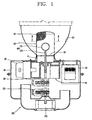
- Fig. 1 is a sectional view illustrating a structure of a related art electrodeless lighting system
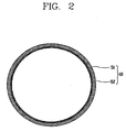
- Fig. 2 is a linear sectional view taken along the line 'II -II' of Fig. 1.
- a related art electrodeless lighting system comprises a casing 10 in which a high voltage generator 20, a microwave generator 30 and a wave guide 40 are disposed, and a resonator 50 and an electrodeless bulb 60 each of which is disposed outside the casing 10.
- the electrodeless lighting system can be operated such that microwaves generated from the microwave generator 30 are induced to the resonator 50 via the wave guide 40 and accordingly inactive gases filled in the electrodeless bulb 60 are plasmarized to thereby emit light.
- the wave guide 40 is formed in a cylindrical tube. One side surface of the wave guide 40 is connected to the microwave generator 30. A resonator coupling member 41 having a certain height is protruded from an upper surface of the wave guide 40 along a height (longitudinal) direction of the wave guide 40.
- the resonator coupling member 41 is formed in a ring (annular) shape having a diameter smaller than that of the wave guide 40, and its center is penetrated.
- the resonator 50 is fixedly coupled to an outer side of the resonator coupling member 41.
- the resonator 50 is constituted with a cylindrical mesh having a net-like structure such that the electrodeless bulb 60 is received in its inner space, microwaves are shielded from being discharged to the outside thus to be delivered to the electrodeless bulb 60, and light emitted from the electrodeless bulb 60 is transmitted to the outside.
- the resonator 50 is formed of a steel material thus to form a cylindrical shape.
- a layer 52 coated with silver is provided on an inner surface of the resonator 50 so as to increase a reflectivity of the resonator 50.
- a mirror 70 is formed in a circular plate having the same diameter as that of the resonator coupling member 41 and is in contact with an upper end of the resonator coupling member 41.
- the electrodeless bulb 60 having a certain length is extended from the center portion of the mirror 70 in a height (longitudinal) direction of the wave guide 40 to thus be exposed out of the wave guide 40.
- the electrodeless bulb 60 comprises a spherical light emitting portion 61 having a certain inner volume for filling a filling material, and a fixing portion 62 formed of the same material as that of the light emitting portion 61 and extended from the light emitting portion 61.
- the light emitting portion 61 is installed inside the resonator 50 and the fixing portion 62 is installed to be formed into the center portion of the wave guide 40.
- the fixing portion 62 installed is connected to a motor shaft of a driving motor 90 which is installed in the casing 10 thus to be rotated at a certain speed.
- the light emitting portion 61 is preferably fabricated using a material such as quartz which has a high optical transmittance and an extremely low dielectric loss.
- the filling material filled in the light emitting portion 61 is constituted with a light emitting material such as metal, a halogen group compound, sulfur, selenium, or the like for forming a plasma to emit light, inactive gases such as argon gas, krypton gas, or the like for forming the plasma in the light emitting portion 61 at the beginning of the light emitting, and a discharge-catalyst material such as mercury for facilitating lighting by supporting an initial discharge or adjusting spectrum of light generated.
- a light emitting material such as metal, a halogen group compound, sulfur, selenium, or the like for forming a plasma to emit light
- inactive gases such as argon gas, krypton gas, or the like
- a discharge-catalyst material such as mercury for facilitating lighting by supporting an initial discharge or adjusting spectrum of light generated
- Unexplained numeral 80 denotes a reflector
- 100 denotes a cooling fan
- 110 denotes a second driving motor for rotating the cooling fan 100
- 120 denotes an air duct.
- the high voltage generator 20 boosts an alternative current (AC) power source and applies the boosted high voltage to the microwave generator 30, which is then oscillated by the high voltage to generate microwaves having an extremely high frequency.
- the generated microwaves are radiated (emitted) into the resonator 50 via the wave guide 40 and thereby inactive gases filled in the electrodeless bulb 60 are excited.
- light emitting material are continuously plasmarized to thus emit light which has a specific discharge spectrum.
- the emitted light arrives at a surface of the mirror 70 disposed at a rear side of the electrodeless bulb 60 and then reflected to a front side of the electrodeless bulb 60 thus to light up a space.
- the resonator 50 is formed of the steel material and the silver-coated layer 52 is provided on the inner surface of the resonator 50, so as to increase a reflectivity.
- heat of high temperature generated from the electrodeless bulb 60 discolors (fades) the silver-coated layer 52 to thereby lower the reflectivity. Accordingly, the velocity of light generated from the electrodeless bulb is problematically decreased.
- an object of the present invention is to provide an electrodeless lighting system having an aluminum resonator capable of preventing a decrease in a velocity of light due to a fading of silver coated on a resonator by heat generated from an electrodeless bulb.
- an electrodeless lighting system having an aluminum resonator comprising: an electrodeless bulb for emitting light by plasmarizing light emitting materials filled therein; and a resonator for receiving the electrodeless bulb in an inner space thereof, and for transmitting light generated from the electrodeless bulb, allowing the electrodeless bulb to emit light by shielding microwaves, which have been generated from a microwave generator and then applied to the inner space, from being discharged to the exterior to thus implement a resonance mode, wherein the resonator is formed of an aluminum.
- an electrodeless lighting system having an aluminum resonator comprising: an electrodeless bulb for emitting light by plasmarizing light emitting materials filled therein; and a resonator formed of a steel material for receiving the electrodeless bulb in an inner space thereof, and for transmitting light generated from the electrodeless bulb, allowing the electrodeless bulb to emit light by shielding microwaves, which have been generated from an microwave generator and then applied to the inner space, from being discharged to the exterior to thus implement a resonance mode, wherein an aluminum layer is coated on an inner surface of the resonator.
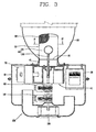
- Fig. 3 is a sectional view illustrating a structure of an electrodeless lighting system having an aluminum resonator in accordance with one embodiment of the present invention
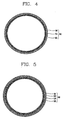
- Fig. 4 is a linear sectional view taken along the line 'IV-IV' of Fig. 3
- Fig. 5 is a sectional view illustrating an electrodeless lighting system having an aluminum coated resonator in accordance with another embodiment of the present invention.
- an electrodeless lighting system having an aluminum resonator 50 in accordance with one embodiment of the present invention comprises an electrodeless bulb 60 for emitting light by plasmarizing light emitting materials filled therein, and a resonator 50 for receiving the electrodeless bulb 60 in an inner space thereof, and for transmitting light generated from the electrodeless bulb 60, allowing the electrodeless bulb 60 to emit light by shielding microwaves, which have been generated from a microwave generator 30 and then applied to the inner space, from being discharged to the exterior to thus implement a resonance mode, wherein the resonator 50 is formed of an aluminum.
- the resonator 50 may be constituted with a cylindrical mesh 56 having a net-like structure such that the electrodeless bulb 60 is received in the inner space thereof, microwaves are shielded from being discharged to the exterior thus to transfer them to the electrodeless bulb 60, and light emitted from the electrodeless bulb 60 is transmitted to the exterior.
- the resonator 50 is formed of a steel material thus to form a cylindrical shape.
- An aluminum oxide layer Al 2 O 3 54 is coated on an inner surface of the mesh 56 to thus prevent the mesh 56 formed of an aluminum from being corroded.
- a high reflection coating layer 55 is formed at an inner surface of the aluminum oxide layer Al 2 O 3 54 to thus increase a reflectivity of the resonator 50.
- the aluminum oxide layer Al 2 O 3 54 is coated on a surface of the mesh 56 formed of the aluminum which is easily oxidized in air so as to prevent the mesh 56 from being oxidized.
- the high voltage generator 20 boosts an alternative current (AC) voltage and applies the boosted high voltage to the microwave generator 30, which is then oscillated to generate microwaves having an extremely high frequency.
- the generated microwaves are radiated into the resonator 50 via a wave guide 40, whereby inactive gases filled in the electrodeless bulb 60 is excited to thereby continuously plasmarize light emitting materials, resulting in generation of light having a specific discharge spectrum.
- the aluminum oxide layer Al 2 O 3 54 formed on the inner surface of the mesh 56 can prevent a corrosion of the resonator 50 formed of the aluminum, and the high reflection coating layer 55 formed on the inner surface of the aluminum oxide layer Al 2 O 3 54 can decrease a loss of light generated from the electrodeless bulb 60.
- the light arrives at the surface of a mirror 70 disposed at a rear side of the electrodeless bulb 60 and then reflected to a front side of the electrodeless bulb 60 to thus light it up.
- Fig. 5 is a sectional view illustrating an electrodeless lighting system having an aluminum coated resonator in accordance with another embodiment of the present invention.
- the same portions as those in the one embodiment of the present invention may have the same reference numerals, and detailed description therefor will not be repeated accordingly.
- a resonator of an electrodeless lighting system having an aluminum coated resonator in accordance with another embodiment of the present invention is formed of the steel material as same as the resonator of the related art electrodeless lighting system.
- An aluminum layer 53 is coated on an inner surface of the resonator 50.
- An aluminum oxide layer 54 is coated on an inner surface of the aluminum layer 53 thus to prevent a corrosion of the aluminum layer 53.
- a high reflection coating layer 55 is disposed on an inner surface of the aluminum oxide layer 54 to increase a reflectivity of the resonator 50.
Landscapes
- Physics & Mathematics (AREA)
- Engineering & Computer Science (AREA)
- Plasma & Fusion (AREA)
- Electromagnetism (AREA)
- Non-Portable Lighting Devices Or Systems Thereof (AREA)
- Discharge Lamps And Accessories Thereof (AREA)
Abstract
A lighting system comprising:
An electrodeless bulb for transmitting light generated by a plasma contained within said bulb; a microwave generator adapted for generating microwave energy for producing and sustaining said plasma;
a metallic mesh resonator adapted for containing said bulb, the resonator being adapted for transmitting light generated by said plasma as well as for preventing leakage of said microwaves to a region exterior of said resonator.
The metallic mesh constituting said resonator may be made of steel or aluminized steel.
An electrodeless bulb for transmitting light generated by a plasma contained within said bulb; a microwave generator adapted for generating microwave energy for producing and sustaining said plasma;
a metallic mesh resonator adapted for containing said bulb, the resonator being adapted for transmitting light generated by said plasma as well as for preventing leakage of said microwaves to a region exterior of said resonator.
The metallic mesh constituting said resonator may be made of steel or aluminized steel.
Description
- The present disclosure relates to a subject matter contained in priority
Korean Application No. 10-2005-0090816, filed on September 28, 2005 - The present invention relates to an electrodeless lighting system having an aluminum resonator, and particularly, to an electrodeless lighting system having an aluminum resonator capable of preventing a decrease in a velocity of light due to a fading of silver coated on a resonator by heat generated from an electrodeless bulb.
- Fig. 1 is a sectional view illustrating a structure of a related art electrodeless lighting system, and Fig. 2 is a linear sectional view taken along the line 'II -II' of Fig. 1.
- As illustrated in Figs. 1 and 2, a related art electrodeless lighting system comprises a
casing 10 in which ahigh voltage generator 20, amicrowave generator 30 and awave guide 40 are disposed, and aresonator 50 and anelectrodeless bulb 60 each of which is disposed outside thecasing 10. The electrodeless lighting system can be operated such that microwaves generated from themicrowave generator 30 are induced to theresonator 50 via thewave guide 40 and accordingly inactive gases filled in theelectrodeless bulb 60 are plasmarized to thereby emit light. - The
wave guide 40 is formed in a cylindrical tube. One side surface of thewave guide 40 is connected to themicrowave generator 30. Aresonator coupling member 41 having a certain height is protruded from an upper surface of thewave guide 40 along a height (longitudinal) direction of thewave guide 40. - The
resonator coupling member 41 is formed in a ring (annular) shape having a diameter smaller than that of thewave guide 40, and its center is penetrated. Theresonator 50 is fixedly coupled to an outer side of theresonator coupling member 41. - The
resonator 50 is constituted with a cylindrical mesh having a net-like structure such that theelectrodeless bulb 60 is received in its inner space, microwaves are shielded from being discharged to the outside thus to be delivered to theelectrodeless bulb 60, and light emitted from theelectrodeless bulb 60 is transmitted to the outside. - The
resonator 50 is formed of a steel material thus to form a cylindrical shape. Alayer 52 coated with silver is provided on an inner surface of theresonator 50 so as to increase a reflectivity of theresonator 50. - A
mirror 70 is formed in a circular plate having the same diameter as that of theresonator coupling member 41 and is in contact with an upper end of theresonator coupling member 41. Theelectrodeless bulb 60 having a certain length is extended from the center portion of themirror 70 in a height (longitudinal) direction of thewave guide 40 to thus be exposed out of thewave guide 40. - The
electrodeless bulb 60, on the other hand, comprises a sphericallight emitting portion 61 having a certain inner volume for filling a filling material, and afixing portion 62 formed of the same material as that of thelight emitting portion 61 and extended from thelight emitting portion 61. - The
light emitting portion 61 is installed inside theresonator 50 and thefixing portion 62 is installed to be formed into the center portion of thewave guide 40. Thefixing portion 62 installed is connected to a motor shaft of a drivingmotor 90 which is installed in thecasing 10 thus to be rotated at a certain speed. - The
light emitting portion 61 is preferably fabricated using a material such as quartz which has a high optical transmittance and an extremely low dielectric loss. The filling material filled in thelight emitting portion 61 is constituted with a light emitting material such as metal, a halogen group compound, sulfur, selenium, or the like for forming a plasma to emit light, inactive gases such as argon gas, krypton gas, or the like for forming the plasma in thelight emitting portion 61 at the beginning of the light emitting, and a discharge-catalyst material such as mercury for facilitating lighting by supporting an initial discharge or adjusting spectrum of light generated. -
Unexplained numeral 80 denotes a reflector, 100 denotes a cooling fan, 110 denotes a second driving motor for rotating thecooling fan - According to such construction, regarding the related art electrodeless lighting system, upon inputting a driving signal to the
high voltage generator 20, thehigh voltage generator 20 boosts an alternative current (AC) power source and applies the boosted high voltage to themicrowave generator 30, which is then oscillated by the high voltage to generate microwaves having an extremely high frequency. The generated microwaves are radiated (emitted) into theresonator 50 via thewave guide 40 and thereby inactive gases filled in theelectrodeless bulb 60 are excited. Accordingly, light emitting material are continuously plasmarized to thus emit light which has a specific discharge spectrum. The emitted light arrives at a surface of themirror 70 disposed at a rear side of theelectrodeless bulb 60 and then reflected to a front side of theelectrodeless bulb 60 thus to light up a space. - However, in the related art electrodeless lighting system, the
resonator 50 is formed of the steel material and the silver-coatedlayer 52 is provided on the inner surface of theresonator 50, so as to increase a reflectivity. As the electrodeless lighting system is used for a long time, heat of high temperature generated from theelectrodeless bulb 60 discolors (fades) the silver-coatedlayer 52 to thereby lower the reflectivity. Accordingly, the velocity of light generated from the electrodeless bulb is problematically decreased. - Therefore, an object of the present invention is to provide an electrodeless lighting system having an aluminum resonator capable of preventing a decrease in a velocity of light due to a fading of silver coated on a resonator by heat generated from an electrodeless bulb.
- To achieve these and other advantages and in accordance with the purpose of the present invention, as embodied and broadly described herein, there is provided an electrodeless lighting system having an aluminum resonator comprising: an electrodeless bulb for emitting light by plasmarizing light emitting materials filled therein; and a resonator for receiving the electrodeless bulb in an inner space thereof, and for transmitting light generated from the electrodeless bulb, allowing the electrodeless bulb to emit light by shielding microwaves, which have been generated from a microwave generator and then applied to the inner space, from being discharged to the exterior to thus implement a resonance mode, wherein the resonator is formed of an aluminum.
- According to another embodiment of the present invention, there is provided an electrodeless lighting system having an aluminum resonator comprising: an electrodeless bulb for emitting light by plasmarizing light emitting materials filled therein; and a resonator formed of a steel material for receiving the electrodeless bulb in an inner space thereof, and for transmitting light generated from the electrodeless bulb, allowing the electrodeless bulb to emit light by shielding microwaves, which have been generated from an microwave generator and then applied to the inner space, from being discharged to the exterior to thus implement a resonance mode, wherein an aluminum layer is coated on an inner surface of the resonator.
- The foregoing and other objects, features, aspects and advantages of the present invention will become more apparent from the following detailed description of the present invention when taken in conjunction with the accompanying drawings.
- The accompanying drawings, which are included to provide a further understanding of the invention and are incorporated in and constitute a part of this specification, illustrate embodiments of the invention and together with the description serve to explain the principles of the invention.
- In the drawings:
- Fig. 1 is a sectional view illustrating a structure of a related art electrodeless lighting system;
- Fig. 2 is a linear sectional view taken along the line 'II -II' of Fig. 1;
- Fig. 3 is a sectional view illustrating a structure of an electrodeless lighting system having an aluminum resonator in accordance with one embodiment of the present invention;
- Fig. 4 is a linear sectional view taken along the line 'IV-IV' of Fig. 3; and
- Fig. 5 is a sectional view illustrating an electrodeless lighting system having an aluminum coated resonator in accordance with another embodiment of the present invention.
- Description will now be given in detail of the present invention, with reference to the accompanying drawings.
- However, the same portions as those in the related art construction may have the same reference numerals, and accordingly detailed description therefor will not be repeated.
- Fig. 3 is a sectional view illustrating a structure of an electrodeless lighting system having an aluminum resonator in accordance with one embodiment of the present invention, Fig. 4 is a linear sectional view taken along the line 'IV-IV' of Fig. 3, and Fig. 5 is a sectional view illustrating an electrodeless lighting system having an aluminum coated resonator in accordance with another embodiment of the present invention.
- As illustrated in the drawings, an electrodeless lighting system having an
aluminum resonator 50 in accordance with one embodiment of the present invention comprises anelectrodeless bulb 60 for emitting light by plasmarizing light emitting materials filled therein, and aresonator 50 for receiving theelectrodeless bulb 60 in an inner space thereof, and for transmitting light generated from theelectrodeless bulb 60, allowing theelectrodeless bulb 60 to emit light by shielding microwaves, which have been generated from amicrowave generator 30 and then applied to the inner space, from being discharged to the exterior to thus implement a resonance mode, wherein theresonator 50 is formed of an aluminum. - The
resonator 50 may be constituted with acylindrical mesh 56 having a net-like structure such that theelectrodeless bulb 60 is received in the inner space thereof, microwaves are shielded from being discharged to the exterior thus to transfer them to theelectrodeless bulb 60, and light emitted from theelectrodeless bulb 60 is transmitted to the exterior. - The
resonator 50 is formed of a steel material thus to form a cylindrical shape. An aluminum oxide layer Al2O3 54 is coated on an inner surface of themesh 56 to thus prevent themesh 56 formed of an aluminum from being corroded. A highreflection coating layer 55 is formed at an inner surface of the aluminum oxide layer Al2O3 54 to thus increase a reflectivity of theresonator 50. - In general, the aluminum oxide layer Al2O3 54 is coated on a surface of the
mesh 56 formed of the aluminum which is easily oxidized in air so as to prevent themesh 56 from being oxidized. - According to such construction, regarding the electrodeless lighting system having the aluminum resonator in accordance with the one embodiment of the present invention, upon inputting a driving signal to the
high voltage generator 20, thehigh voltage generator 20 boosts an alternative current (AC) voltage and applies the boosted high voltage to themicrowave generator 30, which is then oscillated to generate microwaves having an extremely high frequency. The generated microwaves are radiated into theresonator 50 via awave guide 40, whereby inactive gases filled in theelectrodeless bulb 60 is excited to thereby continuously plasmarize light emitting materials, resulting in generation of light having a specific discharge spectrum. - Here, the aluminum oxide layer Al2O3 54 formed on the inner surface of the
mesh 56 can prevent a corrosion of theresonator 50 formed of the aluminum, and the highreflection coating layer 55 formed on the inner surface of the aluminum oxide layer Al2O3 54 can decrease a loss of light generated from theelectrodeless bulb 60. The light arrives at the surface of amirror 70 disposed at a rear side of theelectrodeless bulb 60 and then reflected to a front side of theelectrodeless bulb 60 to thus light it up. - Fig. 5 is a sectional view illustrating an electrodeless lighting system having an aluminum coated resonator in accordance with another embodiment of the present invention. The same portions as those in the one embodiment of the present invention may have the same reference numerals, and detailed description therefor will not be repeated accordingly.
- A resonator of an electrodeless lighting system having an aluminum coated resonator in accordance with another embodiment of the present invention is formed of the steel material as same as the resonator of the related art electrodeless lighting system. An aluminum layer 53 is coated on an inner surface of the
resonator 50. Analuminum oxide layer 54 is coated on an inner surface of the aluminum layer 53 thus to prevent a corrosion of the aluminum layer 53. A highreflection coating layer 55 is disposed on an inner surface of thealuminum oxide layer 54 to increase a reflectivity of theresonator 50.
Claims (10)
- An electrodeless lighting system of an aluminum resonator comprising:an electrodeless bulb for emitting light by plasmarizing light emitting materials filled therein; anda resonator for receiving the electrodeless bulb in an inner space thereof, and for transmitting light generated from the electrodeless bulb, allowing the electrodeless bulb to emit light by shielding microwaves, which have been generated from a microwave generator and then applied to the inner space, from being discharged to the exterior to thus implement a resonance mode,wherein the resonator is formed of an aluminum.
- The electrodeless lighting system of claim 1, wherein a corrosion preventing portion is disposed on an inner surface of the resonator.
- The electrodeless lighting system of claim 2, wherein the corrosion preventing portion denotes an aluminum oxide layer Al2O3 coated on the inner surface of the resonator.
- The electrodeless lighting system of claim 1, 2, or 3, wherein a reflection coating layer is further disposed on the inner surface of the resonator.
- The electrodeless lighting system of claim 4, wherein the reflection coating layer denotes a high reflection coating layer.
- An electrodeless lighting system having an aluminum coated resonator comprising:an electrodeless bulb for emitting light by plasmarizing light emitting materials filled therein; anda resonator formed of a steel material, for receiving the electrodeless bulb in an inner space thereof, and for transmitting light generated from the electrodeless bulb, allowing the electrodeless bulb to emit light by shielding microwaves, which have been generated from a microwave generator and then applied to the inner space, from being discharged to the exterior to thus implement a resonance mode,wherein an aluminum layer is coated on an inner surface of the resonator.
- The electrodeless lighting system of claim 6, wherein a corrosion preventing portion is disposed on an inner surface of the resonator.
- The electrodeless lighting system of claim 7, wherein the corrosion preventing portion denotes an aluminum oxide layer Al2O3 coated on the inner surface of the resonator.
- The electrodeless lighting system of claim 6, 7, or 8, wherein a reflection coating layer is further disposed on the inner surface of the resonator.
- The electrodeless lighting system of claim 9, wherein the reflection coating layer denotes a high reflection coating layer.
Applications Claiming Priority (1)
| Application Number | Priority Date | Filing Date | Title |
|---|---|---|---|
| KR1020050090816A KR100761264B1 (en) | 2005-09-28 | 2005-09-28 | Electrodeless Illuminator with Aluminum Resonator |
Publications (1)
| Publication Number | Publication Date |
|---|---|
| EP1770756A1 true EP1770756A1 (en) | 2007-04-04 |
Family
ID=37622494
Family Applications (1)
| Application Number | Title | Priority Date | Filing Date |
|---|---|---|---|
| EP06020027A Withdrawn EP1770756A1 (en) | 2005-09-28 | 2006-09-25 | Electrodeless lighting system comprising a metalllic mesh resonator |
Country Status (5)
| Country | Link |
|---|---|
| US (1) | US20070069650A1 (en) |
| EP (1) | EP1770756A1 (en) |
| JP (1) | JP2007095691A (en) |
| KR (1) | KR100761264B1 (en) |
| CN (1) | CN100592465C (en) |
Families Citing this family (1)
| Publication number | Priority date | Publication date | Assignee | Title |
|---|---|---|---|---|
| CN103715059B (en) * | 2014-01-02 | 2016-02-10 | 长乐芯聚电子科技研究所 | High brightness microwave lamp |
Citations (3)
| Publication number | Priority date | Publication date | Assignee | Title |
|---|---|---|---|---|
| US6465959B1 (en) * | 1997-06-04 | 2002-10-15 | Fusion Lighting, Inc. | Method and apparatus for improved electrodeless lamp screen |
| WO2003021632A2 (en) * | 2001-08-30 | 2003-03-13 | Quay Technologies Limited | Pulsed uv light source |
| WO2003107725A1 (en) * | 2002-06-14 | 2003-12-24 | Fusion Lighting, Inc. | Microwave electrodeless lamp |
Family Cites Families (10)
| Publication number | Priority date | Publication date | Assignee | Title |
|---|---|---|---|---|
| DE19813709A1 (en) * | 1998-03-27 | 1999-09-30 | Inst Neue Mat Gemein Gmbh | Process for protecting a metallic substrate from corrosion |
| WO2000070651A1 (en) * | 1999-05-12 | 2000-11-23 | Fusion Lighting, Inc. | High brightness microwave lamp |
| KR20010055802A (en) * | 1999-12-13 | 2001-07-04 | 구자홍 | Combined structure of resonator and reflector in electrodeless lamp |
| KR100393780B1 (en) * | 2000-12-18 | 2003-08-02 | 엘지전자 주식회사 | Method for manufacturing resonator of microwave lighting system |
| JP2003249196A (en) * | 2002-02-25 | 2003-09-05 | Matsushita Electric Works Ltd | Microwave electrodeless discharge lamp lighting device |
| JP2005038751A (en) * | 2003-07-16 | 2005-02-10 | Matsushita Electric Works Ltd | Electrodeless discharge lamp lighting device |
| KR100556782B1 (en) * | 2003-12-06 | 2006-03-10 | 엘지전자 주식회사 | Plasma lamp system |
| KR100575666B1 (en) * | 2003-12-13 | 2006-05-03 | 엘지전자 주식회사 | Plasma lamp system |
| KR100585701B1 (en) * | 2004-09-25 | 2006-06-07 | 엘지전자 주식회사 | Resonator of Electrodeless Lighting Equipment |
| KR100631541B1 (en) * | 2004-10-26 | 2006-10-09 | 엘지전자 주식회사 | Street Light System Using Plasma |
-
2005
- 2005-09-28 KR KR1020050090816A patent/KR100761264B1/en not_active Expired - Fee Related
-
2006
- 2006-09-25 EP EP06020027A patent/EP1770756A1/en not_active Withdrawn
- 2006-09-27 JP JP2006262897A patent/JP2007095691A/en not_active Withdrawn
- 2006-09-28 CN CN200610139686A patent/CN100592465C/en not_active Expired - Fee Related
- 2006-09-28 US US11/536,234 patent/US20070069650A1/en not_active Abandoned
Patent Citations (3)
| Publication number | Priority date | Publication date | Assignee | Title |
|---|---|---|---|---|
| US6465959B1 (en) * | 1997-06-04 | 2002-10-15 | Fusion Lighting, Inc. | Method and apparatus for improved electrodeless lamp screen |
| WO2003021632A2 (en) * | 2001-08-30 | 2003-03-13 | Quay Technologies Limited | Pulsed uv light source |
| WO2003107725A1 (en) * | 2002-06-14 | 2003-12-24 | Fusion Lighting, Inc. | Microwave electrodeless lamp |
Also Published As
| Publication number | Publication date |
|---|---|
| KR20070035887A (en) | 2007-04-02 |
| US20070069650A1 (en) | 2007-03-29 |
| CN100592465C (en) | 2010-02-24 |
| JP2007095691A (en) | 2007-04-12 |
| KR100761264B1 (en) | 2007-09-28 |
| CN1941274A (en) | 2007-04-04 |
Similar Documents
| Publication | Publication Date | Title |
|---|---|---|
| RU2278482C1 (en) | Electrode-less lighting system | |
| EP1335407B1 (en) | Electrodeless lighting system and bulb therefor | |
| US20100156295A1 (en) | Electrodeless bulb, and electrodeless lighting system having the same | |
| EP1494265B1 (en) | Lighting apparatus using microwave energy | |
| EP1770756A1 (en) | Electrodeless lighting system comprising a metalllic mesh resonator | |
| CN1855356B (en) | Plasma lighting system | |
| KR100451226B1 (en) | Apparatus for enhancing starting discharge in plasma lighting system | |
| KR100748531B1 (en) | Electrodeless illuminator with metal thin film resonator | |
| JP4259274B2 (en) | Microwave electrodeless discharge lamp device | |
| KR100724461B1 (en) | Electrodeless illuminator with plate resonator | |
| KR100724460B1 (en) | High efficiency electrodeless bulb of electrodeless lighting equipment | |
| KR100748532B1 (en) | Electrodeless illuminator with semi-elliptic resonator | |
| KR100788977B1 (en) | Electrodeless Illuminator with Polygonal Resonator | |
| KR100400401B1 (en) | Lighting apparatus for plasma lighting system | |
| KR100724383B1 (en) | Electrodeless lighting equipment | |
| JP3178368B2 (en) | High frequency electrodeless discharge lamp light reflector and high frequency electrodeless discharge lamp device | |
| KR100641115B1 (en) | Resonator for electrodeless illuminator and electrodeless illuminator with same | |
| US7446484B2 (en) | Middle output electrodeless lighting system | |
| KR100761281B1 (en) | Electrodeless bulb and electrodeless lighting device having same | |
| KR100724467B1 (en) | Anhydrous mercury-free electrode bulbs for electrodeless illuminators with discharge-inducing materials | |
| KR100789300B1 (en) | Resonator for Electrodeless Lighting Equipment | |
| KR100724454B1 (en) | Electrodeless illuminator with multiple slots | |
| KR100724465B1 (en) | Electrodeless illuminator with shape variable resonator | |
| KR100739161B1 (en) | Bulb Eccentric Induction Illuminator | |
| JP2019053897A (en) | Microwave electrodeless lamp and light irradiation device using the same |
Legal Events
| Date | Code | Title | Description |
|---|---|---|---|
| PUAI | Public reference made under article 153(3) epc to a published international application that has entered the european phase |
Free format text: ORIGINAL CODE: 0009012 |
|
| 17P | Request for examination filed |
Effective date: 20061025 |
|
| AK | Designated contracting states |
Kind code of ref document: A1 Designated state(s): AT BE BG CH CY CZ DE DK EE ES FI FR GB GR HU IE IS IT LI LT LU LV MC NL PL PT RO SE SI SK TR |
|
| AX | Request for extension of the european patent |
Extension state: AL BA HR MK YU |
|
| AKX | Designation fees paid |
Designated state(s): DE GB |
|
| STAA | Information on the status of an ep patent application or granted ep patent |
Free format text: STATUS: THE APPLICATION HAS BEEN WITHDRAWN |
|
| 18W | Application withdrawn |
Effective date: 20110713 |