EP1770444A1 - Lithographic apparatus and method for conditioning an interior space of a device manufacturing apparatus - Google Patents
Lithographic apparatus and method for conditioning an interior space of a device manufacturing apparatus Download PDFInfo
- Publication number
- EP1770444A1 EP1770444A1 EP06076806A EP06076806A EP1770444A1 EP 1770444 A1 EP1770444 A1 EP 1770444A1 EP 06076806 A EP06076806 A EP 06076806A EP 06076806 A EP06076806 A EP 06076806A EP 1770444 A1 EP1770444 A1 EP 1770444A1
- Authority
- EP
- European Patent Office
- Prior art keywords
- gas
- gas flow
- component
- shower
- opposite sides
- Prior art date
- Legal status (The legal status is an assumption and is not a legal conclusion. Google has not performed a legal analysis and makes no representation as to the accuracy of the status listed.)
- Granted
Links
Images


Classifications
-
- G—PHYSICS
- G03—PHOTOGRAPHY; CINEMATOGRAPHY; ANALOGOUS TECHNIQUES USING WAVES OTHER THAN OPTICAL WAVES; ELECTROGRAPHY; HOLOGRAPHY
- G03F—PHOTOMECHANICAL PRODUCTION OF TEXTURED OR PATTERNED SURFACES, e.g. FOR PRINTING, FOR PROCESSING OF SEMICONDUCTOR DEVICES; MATERIALS THEREFOR; ORIGINALS THEREFOR; APPARATUS SPECIALLY ADAPTED THEREFOR
- G03F7/00—Photomechanical, e.g. photolithographic, production of textured or patterned surfaces, e.g. printing surfaces; Materials therefor, e.g. comprising photoresists; Apparatus specially adapted therefor
- G03F7/70—Microphotolithographic exposure; Apparatus therefor
- G03F7/708—Construction of apparatus, e.g. environment aspects, hygiene aspects or materials
- G03F7/70908—Hygiene, e.g. preventing apparatus pollution, mitigating effect of pollution or removing pollutants from apparatus
- G03F7/70933—Purge, e.g. exchanging fluid or gas to remove pollutants
-
- G—PHYSICS
- G03—PHOTOGRAPHY; CINEMATOGRAPHY; ANALOGOUS TECHNIQUES USING WAVES OTHER THAN OPTICAL WAVES; ELECTROGRAPHY; HOLOGRAPHY
- G03F—PHOTOMECHANICAL PRODUCTION OF TEXTURED OR PATTERNED SURFACES, e.g. FOR PRINTING, FOR PROCESSING OF SEMICONDUCTOR DEVICES; MATERIALS THEREFOR; ORIGINALS THEREFOR; APPARATUS SPECIALLY ADAPTED THEREFOR
- G03F7/00—Photomechanical, e.g. photolithographic, production of textured or patterned surfaces, e.g. printing surfaces; Materials therefor, e.g. comprising photoresists; Apparatus specially adapted therefor
- G03F7/70—Microphotolithographic exposure; Apparatus therefor
- G03F7/70691—Handling of masks or workpieces
- G03F7/70775—Position control, e.g. interferometers or encoders for determining the stage position
-
- G—PHYSICS
- G03—PHOTOGRAPHY; CINEMATOGRAPHY; ANALOGOUS TECHNIQUES USING WAVES OTHER THAN OPTICAL WAVES; ELECTROGRAPHY; HOLOGRAPHY
- G03F—PHOTOMECHANICAL PRODUCTION OF TEXTURED OR PATTERNED SURFACES, e.g. FOR PRINTING, FOR PROCESSING OF SEMICONDUCTOR DEVICES; MATERIALS THEREFOR; ORIGINALS THEREFOR; APPARATUS SPECIALLY ADAPTED THEREFOR
- G03F7/00—Photomechanical, e.g. photolithographic, production of textured or patterned surfaces, e.g. printing surfaces; Materials therefor, e.g. comprising photoresists; Apparatus specially adapted therefor
- G03F7/70—Microphotolithographic exposure; Apparatus therefor
- G03F7/708—Construction of apparatus, e.g. environment aspects, hygiene aspects or materials
- G03F7/70858—Environment aspects, e.g. pressure of beam-path gas, temperature
- G03F7/70866—Environment aspects, e.g. pressure of beam-path gas, temperature of mask or workpiece
- G03F7/70875—Temperature, e.g. temperature control of masks or workpieces via control of stage temperature
-
- G—PHYSICS
- G03—PHOTOGRAPHY; CINEMATOGRAPHY; ANALOGOUS TECHNIQUES USING WAVES OTHER THAN OPTICAL WAVES; ELECTROGRAPHY; HOLOGRAPHY
- G03F—PHOTOMECHANICAL PRODUCTION OF TEXTURED OR PATTERNED SURFACES, e.g. FOR PRINTING, FOR PROCESSING OF SEMICONDUCTOR DEVICES; MATERIALS THEREFOR; ORIGINALS THEREFOR; APPARATUS SPECIALLY ADAPTED THEREFOR
- G03F7/00—Photomechanical, e.g. photolithographic, production of textured or patterned surfaces, e.g. printing surfaces; Materials therefor, e.g. comprising photoresists; Apparatus specially adapted therefor
- G03F7/70—Microphotolithographic exposure; Apparatus therefor
- G03F7/708—Construction of apparatus, e.g. environment aspects, hygiene aspects or materials
- G03F7/70858—Environment aspects, e.g. pressure of beam-path gas, temperature
- G03F7/70883—Environment aspects, e.g. pressure of beam-path gas, temperature of optical system
Definitions
- the present invention relates to a lithographic apparatus and a method for conditioning an interior space of a device manufacturing apparatus.
- a lithographic apparatus is a machine that applies a desired pattern onto a substrate, usually onto a target portion of the substrate.
- a lithographic apparatus can be used, for example, in the manufacture of integrated circuits (ICs).
- a patterning device which is alternatively referred to as a mask or a reticle, may be used to generate a circuit pattern to be formed on an individual layer of the IC.
- This pattern can be transferred onto a target portion (e.g. comprising part of, one, or several dies) on a substrate (e.g. a silicon wafer). Transfer of the pattern is typically via imaging onto a layer of radiation-sensitive material (resist) provided on the substrate.
- resist radiation-sensitive material
- a single substrate will contain a network of adjacent target portions that are successively patterned.
- lithographic apparatus include so-called steppers, in which each target portion is irradiated by exposing an entire pattern onto the target portion at one time, and so-called scanners, in which each target portion is irradiated by scanning the pattern through a radiation beam in a given direction (the "scanning"-direction) while synchronously scanning the substrate parallel or anti-parallel to this direction. It is also possible to transfer the pattern from the patterning device to the substrate by imprinting the pattern onto the substrate.
- European patent EP 0 498 499 illustrates, in a Figure 18, part of a lithographic apparatus.
- the apparatus includes an interferometer system and a space in which the interferometer beams propagate.
- a constant, preferably laminar stream of air is passed through this space, to obtain a greater accuracy of the interferometer system.
- Both the purity and the temperature of the supplied air can be controlled.
- the air is, for example, of purity class 1 and its temperature is, for example, stable within 0.1 0 C.
- a lithographic apparatus comprising at least a first gas shower which is configured to supply a first gas flow to an interior space of the apparatus, and at least a second gas shower which is configured to supply a second gas flow to the interior space of the apparatus, wherein the gas showers are configured to direct the first gas flow and the second gas flow at least partly towards each other.
- a lithographic apparatus comprising at least one apparatus component having a first side and a second side, faced away from the first side, wherein the apparatus comprises a gas shower system which is configured to supply a first gas flow at least partially towards the first side of the apparatus component, and to supply a second gas flow at least partially towards the second side of the apparatus component.
- a method for conditioning an interior space of a device manufacturing apparatus wherein a first conditioned gas flow and a second conditioned gas flow are being supplied to the interior space, such that the first conditioned gas flow and the second conditioned gas flow are at least partly directed to each other.
- a method for conditioning an interior space of a device manufacturing apparatus wherein a first gas flow is at least partially directed towards a first side of an apparatus component, and a second gas flow is at least partially directed towards a second side of the apparatus component, which second side is faced away from said first side.
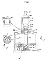
- Figure 1 schematically depicts a lithographic apparatus according to one embodiment of the invention.
- the apparatus comprises:
- the illumination system may include various types of optical components, such as refractive, reflective, magnetic, electromagnetic, electrostatic or other types of optical components, or any combination thereof, for directing, shaping, or controlling radiation.
- optical components such as refractive, reflective, magnetic, electromagnetic, electrostatic or other types of optical components, or any combination thereof, for directing, shaping, or controlling radiation.
- the support structure supports, i.e. bears the weight of, the patterning device. It holds the patterning device in a manner that depends on the orientation of the patterning device, the design of the lithographic apparatus, and other conditions, such as for example whether or not the patterning device is held in a vacuum environment.
- the support structure can use mechanical, vacuum, electrostatic or other clamping techniques to hold the patterning device.
- the support structure may be a frame or a table, for example, which may be fixed or movable as required.
- the support structure may ensure that the patterning device is at a desired position, for example with respect to the projection system. Any use of the terms "reticle” or “mask” herein may be considered synonymous with the more general term "patterning device.”
- patterning device used herein should be broadly interpreted as referring to any device that can be used to impart a radiation beam with a pattern in its cross-section such as to create a pattern in a target portion of the substrate. It should be noted that the pattern imparted to the radiation beam may not exactly correspond to the desired pattern in the target portion of the substrate, for example if the pattern includes phase-shifting features or so called assist features. Generally, the pattern imparted to the radiation beam will correspond to a particular functional layer in a device being created in the target portion, such as an integrated circuit.
- the patterning device may be transmissive or reflective.
- Examples of patterning devices include masks, programmable mirror arrays, and programmable LCD panels.
- Masks are well known in lithography, and include mask types such as binary, alternating phase-shift, and attenuated phase-shift, as well as various hybrid mask types.
- An example of a programmable mirror array employs a matrix arrangement of small mirrors, each of which can be individually tilted so as to reflect an incoming radiation beam in different directions. The tilted mirrors impart a pattern in a radiation beam which is reflected by the mirror matrix.
- projection system used herein should be broadly interpreted as encompassing any type of projection system, including refractive, reflective, catadioptric, magnetic, electromagnetic and electrostatic optical systems, or any combination thereof, as appropriate for the exposure radiation being used, or for other factors such as the use of an immersion liquid or the use of a vacuum. Any use of the term “projection lens” herein may be considered as synonymous with the more general term “projection system”.
- the apparatus is of a transmissive type (e.g. employing a transmissive mask).
- the apparatus may be of a reflective type (e.g. employing a programmable mirror array of a type as referred to above, or employing a reflective mask).
- the lithographic apparatus may be of a type having two (dual stage) or more substrate tables (and/or two or more mask tables). In such "multiple stage” machines the additional tables may be used in parallel, or preparatory steps may be carried out on one or more tables while one or more other tables are being used for exposure.
- the lithographic apparatus may also be of a type wherein at least a portion of the substrate may be covered by a liquid having a relatively high refractive index, e.g. water, so as to fill a space between the projection system and the substrate.
- a liquid having a relatively high refractive index e.g. water
- An immersion liquid may also be applied to other spaces in the lithographic apparatus, for example, between the mask and the projection system. Immersion techniques are well known in the art for increasing the numerical aperture of projection systems.
- immersion as used herein does not mean that a structure, such as a substrate, must be submerged in liquid, but rather only means that liquid is located between the projection system and the substrate during exposure.
- the illuminator IL receives a radiation beam from a radiation source SO.
- the source and the lithographic apparatus may be separate entities, for example when the source is an excimer laser. In such cases, the source is not considered to form part of the lithographic apparatus and the radiation beam is passed from the source SO to the illuminator IL with the aid of a beam delivery system BD comprising, for example, suitable directing mirrors and/or a beam expander. In other cases the source may be an integral part of the lithographic apparatus, for example when the source is a mercury lamp.
- the source SO and the illuminator IL, together with the beam delivery system BD if required, may be referred to as a radiation system.
- the illuminator IL may comprise an adjuster AD for adjusting the angular intensity distribution of the radiation beam.
- an adjuster AD for adjusting the angular intensity distribution of the radiation beam.
- the illuminator IL may comprise various other components, such as an integrator IN and a condenser CO.
- the illuminator may be used to condition the radiation beam, to have a desired uniformity and intensity distribution in its cross-section.
- the radiation beam B is incident on the patterning device (e.g., mask MA), which is held on the support structure (e.g., mask table MT), and is patterned by the patterning device. Having traversed the mask MA, the radiation beam B passes through the projection system PS, which focuses the beam onto a target portion C of the substrate W.
- the substrate table WT can be moved accurately, e.g. so as to position different target portions C in the path of the radiation beam B.
- the first positioner PM and another position sensor can be used to accurately position the mask MA with respect to the path of the radiation beam B, e.g. after mechanical retrieval from a mask library, or during a scan.
- movement of the mask table MT may be realized with the aid of a long-stroke module (coarse positioning) and a short-stroke module (fine positioning), which form part of the first positioner PM.
- movement of the substrate table WT may be realized using a long-stroke module and a short-stroke module, which form part of the second positioner PW.
- the mask table MT may be connected to a short-stroke actuator only, or may be fixed.
- Mask MA and substrate W may be aligned using mask alignment marks M1, M2 and substrate alignment marks P1, P2.
- the substrate alignment marks as illustrated occupy dedicated target portions, they may be located in spaces between target portions (these are known as scribe-lane alignment marks).
- the mask alignment marks may be located between the dies.
- the depicted apparatus could be used in at least one of the following modes:
- the apparatus can include at least one interferometer system IF, as well as at least one gas shower which is arranged to supply laminar gas to at least part of an optical path OP of said interferometer system IF. This is depicted schematically in figures 1 -8.
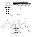
- Figure 2 depicts part of a conventional gas shower system, to condition part of the interior of the apparatus, for example a part of a substrate zone SZ of the apparatus (see Fig. 1) which is traversed by substantially parallel paths OP of optical beams.
- the beam paths OP are shown in cross-section, and can extend perpendicular to the plane of the drawing.
- the respective beams can be, for example, interferometer beams of an interferometer positioning system.
- the interferometer system can be, for example, similar to the system described in EP 0 498 499 A , or be configured differently.
- the optical paths OP can be paths of interferometer beams to position a substrate table or substrate support in an XY-plane (see Fig.
- the apparatus can comprise a substrate support which is moveable in an X- and/or Y- direction with respect to a projection system.
- the interferometer system can be a system for providing X- and/or Y-positioning of such a movable substrate support. Said X- and Y directions can be orthogonal directions.
- a component 10 of the apparatus extends near (above in the drawing) the optical paths OP. Therefore, this component 10 occupies part of the space near the optical paths OP.
- This apparatus component 10 can extend, for example substantially all along the optical paths OP (viewed in a direction perpendicular to the plane of the drawing). Also, the component 10 can extend substantially parallel to the nearby optical beam paths OP (see also Fig. 4, concerning the embodiment described below).
- this component 10 can be a mirror, for example an elongated mirror which can be installed to provide a positioning of a substrate holder in a transversal direction with respect to the optical paths OP, for example a Z-direction which is orthogonal to said X- and Y- direction.
- this component 10 that extends near (above, in the Figures) the optical paths OP can be, for example, a sensor, or a different apparatus component.
- one gas shower extends 101 next to the apparatus component 10, to supply a respective flow of conditioned gas to the interior space.
- the conditioned gas can be, for example, an inert gas, a gas mixture, air, or a different gas.
- the conditioned gas can be ultra clean air of purity class 1.
- the temperature of the gas can be relatively stable, for example, stable within 0.1 0 C and particularly stable within 0.001 0 C. It is known from the prior art how such a thermally stable gas can be provided.
- the gas shower 101 can extend substantially all along the optical paths OP (viewed in a direction perpendicular to the drawing), and/or for example substantially all along the length of the mentioned apparatus component 10, depending on the length of that component 10 with respect to the length of the optical paths OP.
- the gas shower 101 can extend inbetween a projection lens or projection system PS and interferometer "block" IF (see Fig. 1), depending on the arrangement and orientation of the optical paths OP.
- the gas shower 101 does not extend on a side of the substrate support WS or projection lens PL that is faced away from said part of the interferometer system IF.
- the gas shower 101 extends substantially on one lateral side of the projection lens PL.
- the gas shower system can be used to condition the paths OP of the interferometer beams to 0.001 degrees C stability. Because of the location of the apparatus component 10, the gas shower 101 can not condition the optical paths OP from above (in Fig. 2).
- the gas shower 101 is equipped with inclined and diverging vanes 111 plus a curved vane 112 called "slat", to bend gas around the component 10 to condition the optical beams (this is comparable to airplane flap technology).
- Figures 3-4 depict an embodiment, which differs from the embodiment shown in Fig. 2, in that the apparatus includes a gas shower system comprising a first gas shower 1 which is configured to supply a first substantially laminar gas flow g 1 to the interior space of the apparatus, and a second gas shower 2 which is configured to supply a second substantially laminar gas flow g 2 to the interior space.
- Both the first and second gas flow g 1 , g 2 can be, for example the above-mentioned conditioned gas.
- the component 10 of the apparatus extends at least partially between opposite gas outlet sides 3, 4 of the first and second gas shower 1, 2.
- the component 10 abuts or is located near the region that is traversed by substantially parallel parts of the interferometer beams.
- the component 10 can be, for example, a mirror which can be used in the positioning of a substrate support WT, a sensor, of a different component.
- the mentioned component 10 is provided for positioning a substrate support WT in a Z-direction (see Fig. 1 and Fig. 3).
- the apparatus component is provided with a first side 13 and a second side 14.
- the second side 14 of the component 10 is substantially faced away from the first side 13.
- the apparatus component 10 can comprise a third side 15 extending between the first and second side 13, 14.
- the third side 15 comprises a mirror surface, to reflect one or more positioning beams (not depicted).
- the apparatus component 10 can have a substantially rectangular or square cross-section, or be shaped differently.
- the gas shower system 1, 2 is configured to supply the first gas flow g 1 at least partially towards the first side 13 of the apparatus component 10, and to supply the second gas flow g 2 at least partially towards the second side 14 of the apparatus component 10.
- opposite sides 3, 4 of the gas showers 1, 2 are configured to supply the first and second gas flows.
- at least parts of the first and second gas flow g 1 , g 2 meet each other in front of the third side 15 of the apparatus component 10 during use, particularly to condition the optical paths OP.
- other parts of the gas flows g 1 , g 2 can be directed in an opposite direction, for example along the apparatus component 10, away from the optical paths OP, as is clearly depicted in Fig. 3.
- the first and second gas shower 1, 2 of the gas shower system can be arranged such, that the first gas flow g 1 and the second gas flow g 2 are at least partly directed to each other, as is clearly visible in Fig. 3, and towards the further apparatus component 10 which extends between, or reaches between, the gas showers 1, 2.
- the assembly of two gas showers 1, 2 can be spaced-apart from each other. Also, each of the gas showers 1, 2 can be spaced-apart from the further apparatus component 10. Also, in an embodiment, the gas showers 1, 2 can extend inbetween a projection lens or projection system PS and interferometer "block" IF (see Fig. 1), depending on the arrangement and orientation of the optical paths OP. For example, in one embodiment, the gas showers 1, 2 do not extend on a side of the substrate support WS or projection lens PL that is faced away from said part of the interferometer system IF. Thus, in the present embodiment, the gas showers 1, 2 can extend substantially on one lateral side of the projection lens PL.
- assemblies of gas showers 1, 2 extend on various sides of the substrate support WS or projection lens PL, depending for example on the arrangement of the interferometer system.
- gas showers 1, 2 can extend on more than one lateral side of the projection lens PL, for example on opposite lateral sides of the projection lens PL.
- the two gas showers 1, 2 extend substantially parallel with respect to each other, and substantially parallel with respect of respective parallel optical paths OP to be conditioned by the gas flows.
- the apparatus can comprise at least one interferometer system for positioning at least part of the apparatus (such as a substrate holder) utilizing one or more interferometer beams, wherein the first gas shower 1 is configured to supply at least part of the first gas flow g 1 to the region which is traversed by the interferometer beam.
- the second gas shower 2 is configured to supply at least part of the second gas flow g 2 to that region.
- each gas shower 1, 2 can be arranged and configured in various ways.
- each gas shower 1, 2 can include one or more suitable gas outlet sides 3, 4 to disperse laminar gas flows g 1 , g 2 into the apparatus.
- Each of the outlet sides 3, 4 can be provided, for example, with a porous material, a suitable gas disperser, mono filament cloth, one or more sheets having gas apertures, or a different gas distributor.
- Each gas shower outlet side 3, 4 can include one or more layers of one or more materials.
- the outlet side 3, 4 can be, or provide, a wall or wall part of an upstream gas distribution chamber of the respective gas shower 1, 2.
- the gas flows g 1 , g 2 flow substantially perpendicularly from the respective outlet sides 3, 4.
- each gas shower 1, 2, or a respective gas outlet side 3, 4, is configured to generate a substantially uniform laminar gas flow g from gas that is being supplied to the gas shower during use.
- One or more gas sources, to supply gas to the gas showers 3, 4, are not depicted.
- each gas shower 1, 2 can include a high-velocity part HV and an upstream low velocity part LV.
- the high velocity parts can be located near the opposite sides 3, 4 of the gas showers 1, 2.
- gas of a relatively high velocity for example about 1 m/s or a different velocity
- upstream low velocity gas shower parts can also be arranged to feed gas to the interior space, as has been depicted by arrows g 3 , g 4 .
- the opposite sides 3, 4 of the first and second gas shower 1, 2 can be arranged to direct the first gas flow and the second gas flow at least towards each other, as in the present embodiment, and towards the first and second side 13, 14 of the component 10.
- the opposite sides 3, 4 of the gas showers are arranged to supply respective diverging gas flows g 1 , g 2 to the interior space.
- each gas flow g 1 , g 2 as such diverges at least party.
- each gas flow g 1 , g 2 can be diverging when viewed in a virtual plane which is perpendicular to respective optical paths OP, for example a XZ or YZ plane.
- Each diverging gas flow g 1 , g 2 can reach a respective side 13, 14 of the apparatus component 10, as well as the optical paths OP that are located near that apparatus component 10.
- the opposite sides 3, 4 of the first and second gas shower can simply be curved surfaces, or convex surfaces, as is shown in Fig. 3, and be provided with a suitable gas distributor or gas dispersing material, as has been described above.
- the outer side of each gas shower 1, 2 can include a convex gas distribution edge or tip, which edge or tip is at least faced towards the nearby apparatus component 10, and towards said optical paths OP extending in front of the third side 15 of the apparatus component 10.
- the opposite gas shower sides 3, 4 can be arranged in various other ways, and can have, for example, tapered tips, inclined gas passages (see below), or a different configuration.
- one or both gas showers can be configured to provide a respective converging gas flow, or a collimated (parallel) gas flow, or in a different way.
- the first and second gas shower 1, 2 can be configured to induce at least one flow wake (or underpressure) in the interior space.
- said flow wake can be induced near said component 10.
- a location of the wake is depicted with a dashed circle FW in Fig. 3.
- the wake FW can, for example, be induced near said component 10, for example between that component 10 and said optical paths OP, and/or in front of the third side of the component 10.
- the wake FW can also extend at least partially in the optical paths OP.
- the first and second gas flow g 1 , g 2 can be directed such, that the respective wake area is substantially closed in between these gas flows g 1 , g 2 and the apparatus component 10.
- an interior space of the apparatus which space can be traversed by interferometer beams, can be conditioned.
- the first conditioned gas flow g 1 and the second conditioned gas flow g 2 can be supplied to the interior space, such that the first conditioned gas flow and the second conditioned gas flow are at least partly directed to each other, and towards the first and second side of the apparatus component 10.
- the first and second gas flow can meet near the apparatus component 10, to condition the area which is traversed by interferometer beams.
- the first and second gas flow can induce an above-mentioned flow wake FW, or underpressure, in the interior space.
- the first and second gas flow are substantially mirror-symmetrical with respect of each other, viewed for example from the intermediate apparatus component 10.
- the flow rates of the gas flows g 1 , g 2 can be substantially the same.
- the gas flows g 1 , g 2 can be different, can have different flow rates and/or somewhat different flow directions with respect to each other.
- the first and second gas shower 1, 2 can be substantially the same, to provide substantially similar respective gas flows (but with mirror symmetrical flow directions).
- the first and second gas shower 1, 2 can arranged differently, and/or be used to provide gas flows that are asymmetrical, viewed from the intermediate apparatus component 10.
- Figures 5 and 6 depict an embodiment, which differs from the embodiment shown in Figures 3 and 4, in that the gas outlet side 3', 4' of each of the gas showers 1', 2, is arranged to direct the respective gas flow g 1 , g 2 under a certain angle into the interior space.
- the gas flows g 1 , g 2 do not flow substantially perpendicularly from the respective outlet sides 3', 4', but include an angle ⁇ smaller than 90° with that side.
- each of the gas flows by itself can still be a diverging gas flow, such as is depicted in Fig. 3, for example diverging when viewed in a virtual plane which is perpendicular to the optical paths OP, for example a XZ plane or YZ plane.
- the two gas flows can at least partly converge, or join each other (see also Fig. 3).
- the passages 9 can enclose angles ⁇ with said shower outlet side, the angles being in the range of about 20 0 -80 0 .
- said angles can be in the range of about 45 0 -55 0 .
- the gas passages 9 can for example include said angles ⁇ with virtual (vertical) YZ planes, which planes extend perpendicularly with respect to said optical paths OP.
- each gas shower 1', 2' can comprise a shower outlet side 3', 4', comprising a plurality of inclined gas passages, as is shown in detail in Fig. 6 (showing part of the outlet side 4' of the second gas shower 2').
- the shower outlet side 3', 4' can comprise a sheet 8 having the plurality of inclined passages 9, each passage extending substantially obliquely through the sheet.
- the sheet 8 can be a metal sheet or an alloy sheet, wherein the passages 9 can be laser drilled passages, etched passages and/or passages manufactured by electric discharge machining.
- each said gas shower outlet side 3', 4' can comprise a thin metal or alloy sheet 8 having a plurality of passages 9, each of the passages 9 extending obliquely with respect to an outer surface of the metal sheet. Also, a plurality of said passages can extend substantially parallel with respect to each other.
- a thickness t of said sheet 8 (measured in a Y direction in Figure 6) can be smaller than about 1 mm.
- said thickness t can be about 0.5 mm or smaller.
- said sheet 8 can be a metal sheet or an alloy sheet, for example stainless steel, or grown nickel, or an alloy on a pattern.
- relatively small gas passages 9 can be manufactured with high accuracy using laser drilling. Gas passages 9 can also be manufactured using different techniques.
- the sheet 8 can be made of plastic, and/or one or more different materials. Besides laser drilling, different manufacturing methods can be applied to provide said passages 9, such as etching the passages, manufacturing the passages by electric discharge machining, and/or using different processes.
- the gas passages 9 can have various diameters or dimensions.
- a diameter or width D of each of said passages 9 can be, for example, smaller than about 0.2 mm.
- said diameter or width can be smaller than about 0.1 mm. Good results are obtained when said diameter or width of each of said passages is about 0.08 mm.
- the lithographic apparatus can include a movable substrate support WT.
- a substrate support WT (see Fig. 1) can be movable in an X direction and a reverse direction.
- the gas showers 1', 2' are preferably arranged to direct said laminar gas at least partly in the same direction as one direction of movement X of the substrate support WT.
- mentioned inclined gas passages 9 can provide gas flows, having a flow direction F having a component which is parallel to said X direction, and a component which is perpendicular with respect to respective outlet sides 3.
- the gas shower system 1',2' can prevent or diminish the occurrence of a (further) wake behind the substrate support, when the substrate support WT moves away from, for example, an interferometer block IF.
- a so called 'first scan effect' wherein relatively unconditioned gas is sucked from the substrate zone SZ into interferometer beam paths OP due to a first scan movement of a substrate support, can be diminished or avoided.
- Figure 7 is a similar view as Fig. 4 of part of a further embodiment.
- the two gas showers 1", 2" are provided with end part 21, 22 that are located close to each other.
- the end parts extend, for example, opposite one of the ends of the further apparatus component 10, for example an end of the apparatus component 10 that is faced away from a projection system PS and/or substrate table WT (se Fig. 1).
- the gas showers 1", 2" can substantially enclose the end of the apparatus component 10.
- Figure 8 depicts part of an alternative embodiment.
- the embodiment of Fig. 8 differs from the embodiment shown in Fig. 3, in that one of the sides 203 of one of the gas showers 201 is configured to provide a converging gas flow g 1 .
- the gas outlet side 203 of the respective gas shower 201 can simply be a suitably curved surface, or concave surface, as is shown in Fig. 8, and be provided with a suitable gas distributor or gas dispersing material, as has been described above.
- the outer side of the respective gas shower 201 can include a concave gas distribution edge or tip, which edge or tip is at least faced towards the nearby apparatus component 10, and towards said optical paths OP extending in front of the third side 15 of the apparatus component 10.
- the converging gas flow g 1 can be converging when viewed in a mentioned virtual plane which is perpendicular to respective optical paths OP, for example a XZ or YZ plane.
- one of the sides 204 of the gas showers 202 is configured to provide a collimated gas flow g 2 , for example a gas flow g 2 of substantially parallel flow components when leaving the gas shower 202.
- the gas outlet side 204 of the respective gas shower 202 can simply be a substantially flat surfaces, as is shown in Fig. 8, and be provided with a suitable gas distributor or gas dispersing material, as has been described above.
- Such a flat gas outlet side 204 can also be at least faced towards the nearby apparatus component 10, and towards said optical paths OP extending in front of the third side 15 of the apparatus component 10.
- the collimated gas flow g 2 can be collimated (or substantially parallel by itself) when viewed in a mentioned virtual plane which is perpendicular to respective optical paths OP, for example a XZ or YZ plane.
- each of the gas shower outlet sides 203, 204 can be provided, for example, with a porous material, a suitable gas disperser, mono filament cloth, one or more sheets having gas apertures, or a different gas distributor.
- Each gas shower outlet side 203, 204 can include one or more layers of one or more materials.
- the outlet side 203, 204 can be, or provide, a wall or wall part of an upstream gas distribution chamber of the respective gas shower 201, 202.
- the gas flows g 1 , g 2 flow substantially perpendicularly from the respective outlet sides 203, 204.
- the opposite gas shower sides 3, 4, 203, 204 can be arranged in various other ways.
- both of the opposite outlet sides can be flat sides, or concave sides.
- one of the outlet sides can be substantially flat or concave (as in Fig. 8), whereas the opposite outlet side of the opposite gas shower can be concave, or be configured to provide an at least partially diverging gas flow (as in Fig. 3).
- the embodiment of Fig. 8 can be combined, for example, with the embodiment shown in Fig. 4, particularly concerning the flow directions of the gas flows g 1 , g 2 .
- the Fig. 8 embodiment can be combined with the embodiment of Figures 5-6, wherein the gas outlet side 203, 204 of one or both of the gas showers can be arranged to direct the respective gas flow g 1 , g 2 under a certain angle into the interior space (for example by providing respective gas outlet sides 203, 204 with inclined gas passages, as has been describes above).
- the embodiments shown in Figures 2-8 can prevent or diminish mixing of conditioned gas shower system gasses with "ambient" gasses, for example less-conditioned substrate zone SZ gas. Besides, decelerating of laminar shower gasses can be prevented in this way. This can lead to a reduction of mixing of conditioned shower gasses with ambient gasses. Therefore, the gas showers 1, 2 can lead to a good conditioning of an interior (or part thereof) of the apparatus, particularly to condition mentioned interferometer beam paths OP. For example, mixing of unconditioned gasses into lower positioned interferometer beams which are relatively remote from the apparatus component 10, see for example Fig. 3, can be prevented relatively well. Paths of these 'lower' interferometer beams are indicated by OP L in Figures 2, 3 and 8.
- the showers 1, 2 can provide two gas supply areas, one on each side 13, 14 of the apparatus component 10.
- the surface or gas supply side 3, 4 of each supply part of each gas shower 1, 2 can be covered or provided with a mono filament cloth to generate a uniform laminar 'down' flow of a certain velocity.
- the two surfaces 3, 4 of the gas showers 1, 2 can, for example, be positioned at an inclined angle towards the apparatus component 10, such that potential mixing zones of low momentum and unconditioned gas can be located outside interferometer paths OP, and such that a flow wake FW under the mirror surface is minimal.
- the gas shower assembly 1, 2 can enclose substantially the entire end of the respective apparatus component (for example as in Fig. 7), for example at the interferometer-part side.
- a top surface of the substrate support can be configured to induce a pressure stagnation point PSP, for example in cooperation with lateral end parts of the gas showers 1, 2.
- a pressure stagnation point PSP can avoid or reduce entrainment of unconditioned gas into interferometer paths OP. This is schematically depicted in Fig. 9, wherein the location of the pressure stagnation point is indicated by a dashed circle PSP.
- lithographic apparatus in the manufacture of ICs
- the lithographic apparatus described herein may have other applications, such as the manufacture of integrated optical systems, guidance and detection patterns for magnetic domain memories, flat-panel displays, liquid-crystal displays (LCDs), thin-film magnetic heads, etc.
- LCDs liquid-crystal displays
- any use of the terms “wafer” or “die” herein may be considered as synonymous with the more general terms “substrate” or "target portion”, respectively.
- the substrate referred to herein may be processed, before or after exposure, in for example a track (a tool that typically applies a layer of resist to a substrate and develops the exposed resist), a metrology tool and/or an inspection tool. Where applicable, the disclosure herein may be applied to such and other substrate processing tools. Further, the substrate may be processed more than once, for example in order to create a multi-layer IC, so that the term substrate used herein may also refer to a substrate that already contains multiple processed layers.
- imprint lithography a topography in a patterning device defines the pattern created on a substrate.
- the topography of the patterning device may be pressed into a layer of resist supplied to the substrate whereupon the resist is cured by applying electromagnetic radiation, heat, pressure or a combination thereof.
- the patterning device is moved out of the resist leaving a pattern in it after the resist is cured.
- UV radiation e.g. having a wavelength of or about 365, 355, 248, 193, 157 or 126 nm
- EUV radiation e.g. having a wavelength in the range of 5-20 nm
- particle beams such as ion beams or electron beams.
- lens may refer to any one or combination of various types of optical components, including refractive, reflective, magnetic, electromagnetic and electrostatic optical components.
- the invention may take the form of a computer program containing one or more sequences of machine-readable instructions describing a method as disclosed above, or a data storage medium (e.g. semiconductor memory, magnetic or optical disk) having such a computer program stored therein.
- a data storage medium e.g. semiconductor memory, magnetic or optical disk
- the first and second gas shower can be separate gas shower units, or be parts of one gas shower unit.
- the first and second gas shower can be part of the same gas shower system, or of different gas shower systems. Together, the first and second gas shower can form a gas shower assembly.
- the first and second gas shower can be integrated with each other, connected to each other, be connected to the same gas supply or be connected to different gas supplies.
- the first and second gas shower can also be configured differently.
- one ore more further gas showers can be provided, as will be clear to the skilled person.
Landscapes
- Health & Medical Sciences (AREA)
- Physics & Mathematics (AREA)
- General Physics & Mathematics (AREA)
- Epidemiology (AREA)
- Public Health (AREA)
- Life Sciences & Earth Sciences (AREA)
- Atmospheric Sciences (AREA)
- Engineering & Computer Science (AREA)
- Environmental & Geological Engineering (AREA)
- Toxicology (AREA)
- Exposure And Positioning Against Photoresist Photosensitive Materials (AREA)
- Exposure Of Semiconductors, Excluding Electron Or Ion Beam Exposure (AREA)
Abstract
Description
- The present invention relates to a lithographic apparatus and a method for conditioning an interior space of a device manufacturing apparatus.
- A lithographic apparatus is a machine that applies a desired pattern onto a substrate, usually onto a target portion of the substrate. A lithographic apparatus can be used, for example, in the manufacture of integrated circuits (ICs). In that instance, a patterning device, which is alternatively referred to as a mask or a reticle, may be used to generate a circuit pattern to be formed on an individual layer of the IC. This pattern can be transferred onto a target portion (e.g. comprising part of, one, or several dies) on a substrate (e.g. a silicon wafer). Transfer of the pattern is typically via imaging onto a layer of radiation-sensitive material (resist) provided on the substrate. In general, a single substrate will contain a network of adjacent target portions that are successively patterned. Known lithographic apparatus include so-called steppers, in which each target portion is irradiated by exposing an entire pattern onto the target portion at one time, and so-called scanners, in which each target portion is irradiated by scanning the pattern through a radiation beam in a given direction (the "scanning"-direction) while synchronously scanning the substrate parallel or anti-parallel to this direction. It is also possible to transfer the pattern from the patterning device to the substrate by imprinting the pattern onto the substrate.
- The application of gas showers is known from the art. For example,
European patent EP 0 498 499 illustrates, in a Figure 18, part of a lithographic apparatus. The apparatus includes an interferometer system and a space in which the interferometer beams propagate. A constant, preferably laminar stream of air is passed through this space, to obtain a greater accuracy of the interferometer system. Both the purity and the temperature of the supplied air can be controlled. The air is, for example, ofpurity class 1 and its temperature is, for example, stable within 0.10 C. - It is desirable to provide a lithography apparatus, wherein the conditioning of at least part of the interior, and/or optical paths, in the apparatus can be improved.
- In an embodiment of the invention, there is provided a lithographic apparatus, comprising at least a first gas shower which is configured to supply a first gas flow to an interior space of the apparatus, and at least a second gas shower which is configured to supply a second gas flow to the interior space of the apparatus, wherein the gas showers are configured to direct the first gas flow and the second gas flow at least partly towards each other.
- Besides, in another embodiment of the invention, there is provided a lithographic apparatus, comprising at least one apparatus component having a first side and a second side, faced away from the first side, wherein the apparatus comprises a gas shower system which is configured to supply a first gas flow at least partially towards the first side of the apparatus component, and to supply a second gas flow at least partially towards the second side of the apparatus component.
- In an embodiment of the invention, there is provided a method for conditioning an interior space of a device manufacturing apparatus, wherein a first conditioned gas flow and a second conditioned gas flow are being supplied to the interior space, such that the first conditioned gas flow and the second conditioned gas flow are at least partly directed to each other.
- Besides, in another embodiment of the invention, there is provided a method for conditioning an interior space of a device manufacturing apparatus, wherein a first gas flow is at least partially directed towards a first side of an apparatus component, and a second gas flow is at least partially directed towards a second side of the apparatus component, which second side is faced away from said first side.
- Embodiments of the invention will now be described, by way of example only, with reference to the accompanying schematic drawings in which corresponding reference symbols indicate corresponding parts, and in which:
- Figure 1 depicts a lithographic apparatus according to an embodiment of the invention;
- Figure 2 schematically depicts part of a conventional gas shower system, in cross-section;
- Figure 3 depicts part of a gas shower system according to an embodiment of the invention;
- Figure 4 schematically depicts a top view of Fig. 3;
- Figure 5 is a similar view as Fig. 4, of an alternative embodiment;
- Figure 6 depicts a detail of a gas outlet side, in cross-section, of a gas shower system according to an embodiment;
- Figure 7 is a top view of part of a further embodiment;
- Figure 8 is similar to Fig. 3, of an other embodiment of the invention; and
- Figure 9 schematically depicts part of an embodiment, in side view.
- Figure 1 schematically depicts a lithographic apparatus according to one embodiment of the invention. The apparatus comprises:
- an illumination system (illuminator) IL configured to condition a radiation beam B (e.g. UV radiation or a different type of radiation).
- a support structure (e.g. a mask table) MT constructed to support a patterning device (e.g. a mask) MA and connected to a first positioner PM configured to accurately position the patterning device in accordance with certain parameters;
- a substrate zone SZ comprising a substrate table or substrate support (e.g. a wafer table) WT constructed to hold a substrate (e.g. a resist-coated wafer) W and connected to a second positioner PW configured to accurately position the substrate in accordance with certain parameters; and
- a projection system (e.g. a refractive projection lens system) PS configured to project a pattern imparted to the radiation beam B by patterning device MA onto a target portion C (e.g. comprising one or more dies) of the substrate W.
- The illumination system may include various types of optical components, such as refractive, reflective, magnetic, electromagnetic, electrostatic or other types of optical components, or any combination thereof, for directing, shaping, or controlling radiation.
- The support structure supports, i.e. bears the weight of, the patterning device. It holds the patterning device in a manner that depends on the orientation of the patterning device, the design of the lithographic apparatus, and other conditions, such as for example whether or not the patterning device is held in a vacuum environment. The support structure can use mechanical, vacuum, electrostatic or other clamping techniques to hold the patterning device. The support structure may be a frame or a table, for example, which may be fixed or movable as required. The support structure may ensure that the patterning device is at a desired position, for example with respect to the projection system. Any use of the terms "reticle" or "mask" herein may be considered synonymous with the more general term "patterning device."
- The term "patterning device" used herein should be broadly interpreted as referring to any device that can be used to impart a radiation beam with a pattern in its cross-section such as to create a pattern in a target portion of the substrate. It should be noted that the pattern imparted to the radiation beam may not exactly correspond to the desired pattern in the target portion of the substrate, for example if the pattern includes phase-shifting features or so called assist features. Generally, the pattern imparted to the radiation beam will correspond to a particular functional layer in a device being created in the target portion, such as an integrated circuit.
- The patterning device may be transmissive or reflective. Examples of patterning devices include masks, programmable mirror arrays, and programmable LCD panels. Masks are well known in lithography, and include mask types such as binary, alternating phase-shift, and attenuated phase-shift, as well as various hybrid mask types. An example of a programmable mirror array employs a matrix arrangement of small mirrors, each of which can be individually tilted so as to reflect an incoming radiation beam in different directions. The tilted mirrors impart a pattern in a radiation beam which is reflected by the mirror matrix.
- The term "projection system" used herein should be broadly interpreted as encompassing any type of projection system, including refractive, reflective, catadioptric, magnetic, electromagnetic and electrostatic optical systems, or any combination thereof, as appropriate for the exposure radiation being used, or for other factors such as the use of an immersion liquid or the use of a vacuum. Any use of the term "projection lens" herein may be considered as synonymous with the more general term "projection system".
- As here depicted, the apparatus is of a transmissive type (e.g. employing a transmissive mask). Alternatively, the apparatus may be of a reflective type (e.g. employing a programmable mirror array of a type as referred to above, or employing a reflective mask).
- The lithographic apparatus may be of a type having two (dual stage) or more substrate tables (and/or two or more mask tables). In such "multiple stage" machines the additional tables may be used in parallel, or preparatory steps may be carried out on one or more tables while one or more other tables are being used for exposure.
- The lithographic apparatus may also be of a type wherein at least a portion of the substrate may be covered by a liquid having a relatively high refractive index, e.g. water, so as to fill a space between the projection system and the substrate. An immersion liquid may also be applied to other spaces in the lithographic apparatus, for example, between the mask and the projection system. Immersion techniques are well known in the art for increasing the numerical aperture of projection systems. The term "immersion" as used herein does not mean that a structure, such as a substrate, must be submerged in liquid, but rather only means that liquid is located between the projection system and the substrate during exposure.
- Referring to figure 1, the illuminator IL receives a radiation beam from a radiation source SO. The source and the lithographic apparatus may be separate entities, for example when the source is an excimer laser. In such cases, the source is not considered to form part of the lithographic apparatus and the radiation beam is passed from the source SO to the illuminator IL with the aid of a beam delivery system BD comprising, for example, suitable directing mirrors and/or a beam expander. In other cases the source may be an integral part of the lithographic apparatus, for example when the source is a mercury lamp. The source SO and the illuminator IL, together with the beam delivery system BD if required, may be referred to as a radiation system.
- The illuminator IL may comprise an adjuster AD for adjusting the angular intensity distribution of the radiation beam. Generally, at least the outer and/or inner radial extent (commonly referred to as σ-outer and σ-inner, respectively) of the intensity distribution in a pupil plane of the illuminator can be adjusted. In addition, the illuminator IL may comprise various other components, such as an integrator IN and a condenser CO. The illuminator may be used to condition the radiation beam, to have a desired uniformity and intensity distribution in its cross-section.
- The radiation beam B is incident on the patterning device (e.g., mask MA), which is held on the support structure (e.g., mask table MT), and is patterned by the patterning device. Having traversed the mask MA, the radiation beam B passes through the projection system PS, which focuses the beam onto a target portion C of the substrate W. With the aid of the second positioner PW and position sensor IF (e.g. an interferometric device, linear encoder or capacitive sensor), the substrate table WT can be moved accurately, e.g. so as to position different target portions C in the path of the radiation beam B. Similarly, the first positioner PM and another position sensor (which is not explicitly depicted in Figure 1) can be used to accurately position the mask MA with respect to the path of the radiation beam B, e.g. after mechanical retrieval from a mask library, or during a scan. In general, movement of the mask table MT may be realized with the aid of a long-stroke module (coarse positioning) and a short-stroke module (fine positioning), which form part of the first positioner PM. Similarly, movement of the substrate table WT may be realized using a long-stroke module and a short-stroke module, which form part of the second positioner PW. In the case of a stepper (as opposed to a scanner) the mask table MT may be connected to a short-stroke actuator only, or may be fixed. Mask MA and substrate W may be aligned using mask alignment marks M1, M2 and substrate alignment marks P1, P2. Although the substrate alignment marks as illustrated occupy dedicated target portions, they may be located in spaces between target portions (these are known as scribe-lane alignment marks). Similarly, in situations in which more than one die is provided on the mask MA, the mask alignment marks may be located between the dies.
- The depicted apparatus could be used in at least one of the following modes:
- 1. In step mode, the mask table MT and the substrate table WT are kept essentially stationary, while an entire pattern imparted to the radiation beam is projected onto a target portion C at one time (i.e. a single static exposure). The substrate table WT is then shifted in the X and/or Y direction so that a different target portion C can be exposed. In step mode, the maximum size of the exposure field limits the size of the target portion C imaged in a single static exposure.
- 2. In scan mode, the mask table MT and the substrate table WT are scanned synchronously while a pattern imparted to the radiation beam is projected onto a target portion C (i.e. a single dynamic exposure). The velocity and direction of the substrate table WT relative to the mask table MT may be determined by the (de-)magnification and image reversal characteristics of the projection system PS. In scan mode, the maximum size of the exposure field limits the width (in the non-scanning direction) of the target portion in a single dynamic exposure, whereas the length of the scanning motion determines the height (in the scanning direction) of the target portion.
- 3. In another mode, the mask table MT is kept essentially stationary holding a programmable patterning device, and the substrate table WT is moved or scanned while a pattern imparted to the radiation beam is projected onto a target portion C. In this mode, generally a pulsed radiation source is employed and the programmable patterning device is updated as required after each movement of the substrate table WT or in between successive radiation pulses during a scan. This mode of operation can be readily applied to maskless lithography that utilizes programmable patterning device, such as a programmable mirror array of a type as referred to above.
- Combinations and/or variations on the above described modes of use or entirely different modes of use may also be employed.
- In an embodiment, the apparatus can include at least one interferometer system IF, as well as at least one gas shower which is arranged to supply laminar gas to at least part of an optical path OP of said interferometer system IF. This is depicted schematically in figures 1 -8.
- Figure 2 depicts part of a conventional gas shower system, to condition part of the interior of the apparatus, for example a part of a substrate zone SZ of the apparatus (see Fig. 1) which is traversed by substantially parallel paths OP of optical beams. In Fig. 2, the beam paths OP are shown in cross-section, and can extend perpendicular to the plane of the drawing. The respective beams can be, for example, interferometer beams of an interferometer positioning system. The interferometer system can be, for example, similar to the system described in
EP 0 498 499 A , or be configured differently. For example, the optical paths OP can be paths of interferometer beams to position a substrate table or substrate support in an XY-plane (see Fig. 1), or in a different direction. For example, as has been described above, the apparatus can comprise a substrate support which is moveable in an X- and/or Y- direction with respect to a projection system. The interferometer system can be a system for providing X- and/or Y-positioning of such a movable substrate support. Said X- and Y directions can be orthogonal directions. - As Fig. 2 depicts, a
component 10 of the apparatus extends near (above in the drawing) the optical paths OP. Therefore, thiscomponent 10 occupies part of the space near the optical paths OP. Thisapparatus component 10 can extend, for example substantially all along the optical paths OP (viewed in a direction perpendicular to the plane of the drawing). Also, thecomponent 10 can extend substantially parallel to the nearby optical beam paths OP (see also Fig. 4, concerning the embodiment described below). For example, thiscomponent 10 can be a mirror, for example an elongated mirror which can be installed to provide a positioning of a substrate holder in a transversal direction with respect to the optical paths OP, for example a Z-direction which is orthogonal to said X- and Y- direction. Also, thiscomponent 10 that extends near (above, in the Figures) the optical paths OP can be, for example, a sensor, or a different apparatus component. - In the conventional apparatus, one gas shower extends 101 next to the
apparatus component 10, to supply a respective flow of conditioned gas to the interior space. The conditioned gas can be, for example, an inert gas, a gas mixture, air, or a different gas. The conditioned gas can be ultra clean air ofpurity class 1. The temperature of the gas can be relatively stable, for example, stable within 0.10 C and particularly stable within 0.0010 C. It is known from the prior art how such a thermally stable gas can be provided. - In Fig. 2, the gas flow is depicted by arrows g. For example, the
gas shower 101 can extend substantially all along the optical paths OP (viewed in a direction perpendicular to the drawing), and/or for example substantially all along the length of the mentionedapparatus component 10, depending on the length of thatcomponent 10 with respect to the length of the optical paths OP. Also, as an example, thegas shower 101 can extend inbetween a projection lens or projection system PS and interferometer "block" IF (see Fig. 1), depending on the arrangement and orientation of the optical paths OP. For example, thegas shower 101 does not extend on a side of the substrate support WS or projection lens PL that is faced away from said part of the interferometer system IF. Thus, in the present embodiments, thegas shower 101 extends substantially on one lateral side of the projection lens PL. - The gas shower system can be used to condition the paths OP of the interferometer beams to 0.001 degrees C stability. Because of the location of the
apparatus component 10, thegas shower 101 can not condition the optical paths OP from above (in Fig. 2). In the conventional system, thegas shower 101 is equipped with inclined and divergingvanes 111 plus acurved vane 112 called "slat", to bend gas around thecomponent 10 to condition the optical beams (this is comparable to airplane flap technology). - Figures 3-4 depict an embodiment, which differs from the embodiment shown in Fig. 2, in that the apparatus includes a gas shower system comprising a
first gas shower 1 which is configured to supply a first substantially laminar gas flow g1 to the interior space of the apparatus, and asecond gas shower 2 which is configured to supply a second substantially laminar gas flow g2 to the interior space. Both the first and second gas flow g1, g2 can be, for example the above-mentioned conditioned gas. - In the embodiment of Figures 3 and 4, the
component 10 of the apparatus extends at least partially between opposite gas outlet sides 3, 4 of the first andsecond gas shower component 10 abuts or is located near the region that is traversed by substantially parallel parts of the interferometer beams. As in the embodiment of Fig.2, thecomponent 10 can be, for example, a mirror which can be used in the positioning of a substrate support WT, a sensor, of a different component. In a further embodiment, the mentionedcomponent 10 is provided for positioning a substrate support WT in a Z-direction (see Fig. 1 and Fig. 3). - In the present embodiment, the apparatus component is provided with a
first side 13 and asecond side 14. Thesecond side 14 of thecomponent 10 is substantially faced away from thefirst side 13. Also, theapparatus component 10 can comprise athird side 15 extending between the first andsecond side third side 15 comprises a mirror surface, to reflect one or more positioning beams (not depicted). For example, theapparatus component 10 can have a substantially rectangular or square cross-section, or be shaped differently. - As is shown, the
gas shower system first side 13 of theapparatus component 10, and to supply the second gas flow g2 at least partially towards thesecond side 14 of theapparatus component 10. Particularly,opposite sides gas showers third side 15 of theapparatus component 10 during use, particularly to condition the optical paths OP. Besides, other parts of the gas flows g1, g2 can be directed in an opposite direction, for example along theapparatus component 10, away from the optical paths OP, as is clearly depicted in Fig. 3. - Also, in the present embodiment, the first and
second gas shower further apparatus component 10 which extends between, or reaches between, thegas showers - The assembly of two
gas showers gas showers further apparatus component 10. Also, in an embodiment, thegas showers gas showers gas showers gas showers gas showers - In Figures 3 and 4, the two
gas showers first gas shower 1 is configured to supply at least part of the first gas flow g1 to the region which is traversed by the interferometer beam. In Fig. 3 and 4, thesecond gas shower 2 is configured to supply at least part of the second gas flow g2 to that region. - Each of the
gas showers gas shower shower outlet side outlet side respective gas shower respective outlet sides - Preferably, each
gas shower gas outlet side gas showers gas shower opposite sides gas showers - Particularly, the
opposite sides second gas shower second side component 10. For example, in the present embodiment, theopposite sides respective side apparatus component 10, as well as the optical paths OP that are located near thatapparatus component 10. To provide diverging gas flows g1, g2, theopposite sides gas shower nearby apparatus component 10, and towards said optical paths OP extending in front of thethird side 15 of theapparatus component 10. The oppositegas shower sides - Besides, the first and
second gas shower component 10. A location of the wake is depicted with a dashed circle FW in Fig. 3. The wake FW can, for example, be induced near saidcomponent 10, for example between thatcomponent 10 and said optical paths OP, and/or in front of the third side of thecomponent 10. The wake FW can also extend at least partially in the optical paths OP. Besides, in an embodiment, the first and second gas flow g1, g2 can be directed such, that the respective wake area is substantially closed in between these gas flows g1, g2 and theapparatus component 10. - During use of the embodiment of Figures 3 and 4, an interior space of the apparatus, which space can be traversed by interferometer beams, can be conditioned. Therein, the first conditioned gas flow g1 and the second conditioned gas flow g2 can be supplied to the interior space, such that the first conditioned gas flow and the second conditioned gas flow are at least partly directed to each other, and towards the first and second side of the
apparatus component 10. Also, for example, during use, the first and second gas flow can meet near theapparatus component 10, to condition the area which is traversed by interferometer beams. Also, during use, in an embodiment, the first and second gas flow can induce an above-mentioned flow wake FW, or underpressure, in the interior space. In a further embodiment, the first and second gas flow are substantially mirror-symmetrical with respect of each other, viewed for example from theintermediate apparatus component 10. For example, the flow rates of the gas flows g1, g2 can be substantially the same. Alternatively, the gas flows g1, g2 can be different, can have different flow rates and/or somewhat different flow directions with respect to each other. As an example, the first andsecond gas shower second gas shower intermediate apparatus component 10. - Figures 5 and 6 depict an embodiment, which differs from the embodiment shown in Figures 3 and 4, in that the gas outlet side 3', 4' of each of the
gas showers 1', 2, is arranged to direct the respective gas flow g1, g2 under a certain angle into the interior space. Particularly, during use, the gas flows g1, g2 do not flow substantially perpendicularly from the respective outlet sides 3', 4', but include an angle β smaller than 90° with that side. Besides, each of the gas flows by itself can still be a diverging gas flow, such as is depicted in Fig. 3, for example diverging when viewed in a virtual plane which is perpendicular to the optical paths OP, for example a XZ plane or YZ plane. However, with respect to each other, the two gas flows can at least partly converge, or join each other (see also Fig. 3). For example, thepassages 9 can enclose angles β with said shower outlet side, the angles being in the range of about 200-800. As an example, said angles can be in the range of about 450-550. - In the present Figures 5, 6, the
gas passages 9 can for example include said angles β with virtual (vertical) YZ planes, which planes extend perpendicularly with respect to said optical paths OP. - The respective gas showers 1', 2' can be constructed in various ways to provide respective inclined gas flows. For example, each gas shower 1', 2' can comprise a shower outlet side 3', 4', comprising a plurality of inclined gas passages, as is shown in detail in Fig. 6 (showing part of the outlet side 4' of the second gas shower 2'). The shower outlet side 3', 4' can comprise a
sheet 8 having the plurality ofinclined passages 9, each passage extending substantially obliquely through the sheet. For example, thesheet 8 can be a metal sheet or an alloy sheet, wherein thepassages 9 can be laser drilled passages, etched passages and/or passages manufactured by electric discharge machining. - In an embodiment, each said gas shower outlet side 3', 4' can comprise a thin metal or
alloy sheet 8 having a plurality ofpassages 9, each of thepassages 9 extending obliquely with respect to an outer surface of the metal sheet. Also, a plurality of said passages can extend substantially parallel with respect to each other. - In an embodiment, a thickness t of said sheet 8 (measured in a Y direction in Figure 6) can be smaller than about 1 mm. For example, said thickness t can be about 0.5 mm or smaller. Also, said
sheet 8 can be a metal sheet or an alloy sheet, for example stainless steel, or grown nickel, or an alloy on a pattern. In that case, relativelysmall gas passages 9 can be manufactured with high accuracy using laser drilling.Gas passages 9 can also be manufactured using different techniques. Also, thesheet 8 can be made of plastic, and/or one or more different materials. Besides laser drilling, different manufacturing methods can be applied to provide saidpassages 9, such as etching the passages, manufacturing the passages by electric discharge machining, and/or using different processes. - The
gas passages 9 can have various diameters or dimensions. A diameter or width D of each of saidpassages 9 can be, for example, smaller than about 0.2 mm. For example, said diameter or width can be smaller than about 0.1 mm. Good results are obtained when said diameter or width of each of said passages is about 0.08 mm. - In an embodiment, the lithographic apparatus can include a movable substrate support WT. For example, in the embodiment of Fig. 5, a substrate support WT (see Fig. 1) can be movable in an X direction and a reverse direction. In that case, in a further embodiment, the gas showers 1', 2' are preferably arranged to direct said laminar gas at least partly in the same direction as one direction of movement X of the substrate support WT. As is shown in Fig. 5, for example, mentioned
inclined gas passages 9 can provide gas flows, having a flow direction F having a component which is parallel to said X direction, and a component which is perpendicular with respect to respective outlet sides 3. In this way, the gas shower system 1',2' can prevent or diminish the occurrence of a (further) wake behind the substrate support, when the substrate support WT moves away from, for example, an interferometer block IF. In this way, a so called 'first scan effect', wherein relatively unconditioned gas is sucked from the substrate zone SZ into interferometer beam paths OP due to a first scan movement of a substrate support, can be diminished or avoided. - Figure 7 is a similar view as Fig. 4 of part of a further embodiment. In figure 7, the two
gas showers 1", 2" are provided withend part further apparatus component 10, for example an end of theapparatus component 10 that is faced away from a projection system PS and/or substrate table WT (se Fig. 1). For example, thegas showers 1", 2" can substantially enclose the end of theapparatus component 10. - Figure 8 depicts part of an alternative embodiment. The embodiment of Fig. 8 differs from the embodiment shown in Fig. 3, in that one of the
sides 203 of one of thegas showers 201 is configured to provide a converging gas flow g1. To this aim, for example, thegas outlet side 203 of therespective gas shower 201 can simply be a suitably curved surface, or concave surface, as is shown in Fig. 8, and be provided with a suitable gas distributor or gas dispersing material, as has been described above. For example, the outer side of therespective gas shower 201 can include a concave gas distribution edge or tip, which edge or tip is at least faced towards thenearby apparatus component 10, and towards said optical paths OP extending in front of thethird side 15 of theapparatus component 10. For example, the converging gas flow g1, can be converging when viewed in a mentioned virtual plane which is perpendicular to respective optical paths OP, for example a XZ or YZ plane. - In the embodiment of Fig. 8, also, one of the
sides 204 of thegas showers 202 is configured to provide a collimated gas flow g2, for example a gas flow g2 of substantially parallel flow components when leaving thegas shower 202. To this aim, for example, thegas outlet side 204 of therespective gas shower 202 can simply be a substantially flat surfaces, as is shown in Fig. 8, and be provided with a suitable gas distributor or gas dispersing material, as has been described above. Such a flatgas outlet side 204 can also be at least faced towards thenearby apparatus component 10, and towards said optical paths OP extending in front of thethird side 15 of theapparatus component 10. For example, the collimated gas flow g2, can be collimated (or substantially parallel by itself) when viewed in a mentioned virtual plane which is perpendicular to respective optical paths OP, for example a XZ or YZ plane. - Also, in the embodiment of Fig. 8, each of the gas shower outlet sides 203, 204 can be provided, for example, with a porous material, a suitable gas disperser, mono filament cloth, one or more sheets having gas apertures, or a different gas distributor. Each gas
shower outlet side outlet side respective gas shower - The opposite
gas shower sides - Also, the embodiment of Fig. 8 can be combined, for example, with the embodiment shown in Fig. 4, particularly concerning the flow directions of the gas flows g1, g2. On the other hand, the Fig. 8 embodiment can be combined with the embodiment of Figures 5-6, wherein the
gas outlet side - The embodiments shown in Figures 2-8 can prevent or diminish mixing of conditioned gas shower system gasses with "ambient" gasses, for example less-conditioned substrate zone SZ gas. Besides, decelerating of laminar shower gasses can be prevented in this way. This can lead to a reduction of mixing of conditioned shower gasses with ambient gasses. Therefore, the
gas showers apparatus component 10, see for example Fig. 3, can be prevented relatively well. Paths of these 'lower' interferometer beams are indicated by OPL in Figures 2, 3 and 8. - The
showers side apparatus component 10. As follows from the above, the surface orgas supply side gas shower surfaces gas showers apparatus component 10, such that potential mixing zones of low momentum and unconditioned gas can be located outside interferometer paths OP, and such that a flow wake FW under the mirror surface is minimal. It was previously believed that relatively large amounts of unconditioned gas would be sucked into this flow wake FW, particularly at outer ends of theapparatus component 10, for example near an interferometer-part IF and near the projection system PL (see Fig. 1). Now. experiments have surprisingly shown, however, that this is happening only very slightly. To further limit the entrainment of unconditioned gas, thegas shower assembly - Besides, near the projection system PS, a top surface of the substrate support can be configured to induce a pressure stagnation point PSP, for example in cooperation with lateral end parts of the
gas showers - Although specific reference may be made in this text to the use of lithographic apparatus in the manufacture of ICs, it should be understood that the lithographic apparatus described herein may have other applications, such as the manufacture of integrated optical systems, guidance and detection patterns for magnetic domain memories, flat-panel displays, liquid-crystal displays (LCDs), thin-film magnetic heads, etc. The skilled artisan will appreciate that, in the context of such alternative applications, any use of the terms "wafer" or "die" herein may be considered as synonymous with the more general terms "substrate" or "target portion", respectively. The substrate referred to herein may be processed, before or after exposure, in for example a track (a tool that typically applies a layer of resist to a substrate and develops the exposed resist), a metrology tool and/or an inspection tool. Where applicable, the disclosure herein may be applied to such and other substrate processing tools. Further, the substrate may be processed more than once, for example in order to create a multi-layer IC, so that the term substrate used herein may also refer to a substrate that already contains multiple processed layers.
- Although specific reference may have been made above to the use of embodiments of the invention in the context of optical lithography, it will be appreciated that the invention may be used in other applications, for example imprint lithography, and where the context allows, is not limited to optical lithography. In imprint lithography a topography in a patterning device defines the pattern created on a substrate. The topography of the patterning device may be pressed into a layer of resist supplied to the substrate whereupon the resist is cured by applying electromagnetic radiation, heat, pressure or a combination thereof. The patterning device is moved out of the resist leaving a pattern in it after the resist is cured.
- The terms "radiation" and "beam" used herein encompass all types of electromagnetic radiation, including ultraviolet (UV) radiation (e.g. having a wavelength of or about 365, 355, 248, 193, 157 or 126 nm) and extreme ultra-violet (EUV) radiation (e.g. having a wavelength in the range of 5-20 nm), as well as particle beams, such as ion beams or electron beams.
- The term "lens", where the context allows, may refer to any one or combination of various types of optical components, including refractive, reflective, magnetic, electromagnetic and electrostatic optical components.
- While specific embodiments of the invention have been described above, it will be appreciated that the invention may be practiced otherwise than as described. For example, the invention may take the form of a computer program containing one or more sequences of machine-readable instructions describing a method as disclosed above, or a data storage medium (e.g. semiconductor memory, magnetic or optical disk) having such a computer program stored therein.
- The descriptions above are intended to be illustrative, not limiting. Thus, it will be apparent to one skilled in the art that modifications may be made to the invention as described without departing from the scope of the claims set out below.
- For example, the first and second gas shower can be separate gas shower units, or be parts of one gas shower unit. Also, the first and second gas shower can be part of the same gas shower system, or of different gas shower systems. Together, the first and second gas shower can form a gas shower assembly. Besides, the first and second gas shower can be integrated with each other, connected to each other, be connected to the same gas supply or be connected to different gas supplies. The first and second gas shower can also be configured differently. Besides, one ore more further gas showers can be provided, as will be clear to the skilled person.
Claims (54)
- A lithographic apparatus, comprising at least a first gas shower which is configured to supply a first gas flow to an interior space of the apparatus, and at least a second gas shower which is configured to supply a second gas flow to the interior space of the apparatus, wherein the gas showers are configured to direct the first gas flow and the second gas flow at least partly towards each other.
- Apparatus according to claim 1, wherein a component of the apparatus extends at least partially between opposite sides of the first and second gas shower.
- Apparatus according to claim 2, wherein the component is a mirror.
- Apparatus according to any of the preceding claims, wherein the apparatus comprises at least one interferometer system for positioning at least part of the apparatus utilizing one or more interferometer beams, wherein the first gas shower is configured to supply at least part of the first gas flow to a region which is traversed by the one or more interferometer beams.
- Apparatus according to claims 2 and 4, wherein the component abuts or is located near the region that is traversed by the at least one interferometer beam.
- Apparatus according to claim 4 or 5, wherein the second gas shower is configured to supply at least part of the second gas flow to the region which is traversed by the interferometer beam.
- Apparatus according to any of claims 4-6, wherein opposite sides of the first and second gas shower extend substantially parallel to at least one path of the interferometer beam.
- Apparatus according to any of claims 4-7, wherein the apparatus comprises a substrate support which is moveable in an X- and/or Y- direction with respect to a projection system, wherein the interferometer system is a system for providing X-and/or Y- positioning of the movable substrate support.
- Apparatus according to claims 3 and 8, wherein the mirror is provided for positioning the substrate support in a Z-direction.
- Apparatus according to any of the preceding claims, wherein at least opposite sides of the first and second gas shower are arranged to supply the first gas flow and the second gas flow to the interior space.
- Apparatus according to any of the preceding claims, wherein at least one of the opposite sides of the first and second gas shower is a curved surface.
- Apparatus according to any of the preceding claims, wherein at least one of the opposite sides of the first and second gas shower is arranged to supply a converging or a diverging gas flow to the interior space.
- Apparatus according to any of the preceding claims, wherein at least one of the opposite sides of the first and second gas shower is a concave surface.
- Apparatus according to any of the preceding claims, wherein at least one of the opposite sides of the first and second gas shower is a substantially flat surface.
- A lithographic apparatus according to any of the preceding claims, wherein the apparatus comprises a substrate support which is moveable with respect to a projection system, wherein at least the first gas shower is arranged to direct part of the respective gas flow at least partly in the same direction as a first direction of movement of the substrate support.
- Apparatus according to any of the preceding claims, wherein the at least first and second gas shower are configured to induce at least one flow wake in the interior space.
- Apparatus according to claims 2 and 16, wherein the flow wake is induced near the component.
- Apparatus according to any of the preceding claims, wherein at least the first gas shower comprises a shower outlet side comprising a plurality of inclined gas passages.
- Apparatus according to claim 18, wherein the shower outlet side comprises a sheet having the plurality of inclined passages, each passage extending substantially obliquely through the sheet.
- Apparatus according to claim 19, wherein the sheet is a metal sheet or an alloy sheet, wherein the passages are laser drilled passages, etched passages and/or passages manufactured by electric discharge machining.
- A lithographic apparatus according to any of the preceding claims, comprising at least one apparatus component having a first side and a second side, faced away from the first side, wherein the apparatus comprises a gas shower system which is configured to supply a first gas flow at least partially towards the first side of the apparatus component, and to supply a second gas flow at least partially towards the second side of the apparatus component.
- Apparatus according to claim 21, wherein the gas shower system comprises opposite sides which are configured to supply the first and second gas flows.
- Apparatus according to claim 22, wherein the apparatus component extends at least partially between the opposite sides of the gas shower system.
- Apparatus according to claim 22 or 23, wherein opposite sides of the gas shower system extend substantially parallel to at least one path of the interferometer beam.
- Apparatus according to any of claims 22-24, wherein the opposite sides of the gas shower system are mirror symmetrical.
- Apparatus according to any of claims 22-25, wherein the apparatus component comprises a third side extending between the first and second side, wherein at least parts of the first and second gas flow meet each other in front of the third side of the apparatus component during use.
- Apparatus according to any of claims 21-26, wherein the apparatus component is a mirror.
- Apparatus according to any of claims 21-27, wherein the apparatus comprises at least one interferometer system for positioning at least part of the apparatus utilizing one or more interferometer beams, wherein the gas shower system is configured to supply at least part of the first and second gas flows to a region which is traversed by the interferometer beam.
- Apparatus according to claims 21 and 28, wherein the apparatus component abuts or is located near the region that is traversed by the at least one interferometer beam.
- Apparatus according to any of claims 22-29, wherein at least one of the opposite sides of the gas shower system is a curved surface.
- Apparatus according to any of claims 22-30, wherein at least one of the opposite sides of the gas shower system is arranged to supply a converging or a diverging gas flow towards the apparatus component.
- Apparatus according to claim any of claims 22-31, wherein at least one of the opposite sides of the gas shower system is a concave surface.
- Apparatus according to any of claims 22-32, wherein at least one of the opposite sides of the gas shower system is a substantially flat surface.
- Apparatus according to any of claims 22-33, wherein at least one of the opposite sides of the gas shower system is arranged to supply a collimated gas flow towards the apparatus component.
- Method for conditioning an interior space of a device manufacturing apparatus, wherein a first conditioned gas flow and a second conditioned gas flow are being supplied to the interior space, such that the first conditioned gas flow and the second conditioned gas flow are at least partly directed to each other.
- Method according to claim 35, wherein parts of the first and second gas flow meet each other near a component of the apparatus.
- Method according to claim 36, wherein the component is a mirror.
- Method according to any of claims 35-36, wherein at least one interferometer beam traverses the interior space, wherein the path of the interferometer beam is conditioned by said first and/or second gas flow.
- Method according to claims 36 and 38, wherein the component of the apparatus abuts or is located near the region that is traversed by the at least one interferometer beam.
- Method according to any of claims 36-39, wherein the first gas flow is at least directed towards a first side of the component of the apparatus, the second gas flow is at least directed to a second side of the component of the apparatus, the first side and the second side of the component being faced away from each other.
- Method according to any of claims 35-40, wherein the first and second gas flow induce a flow wake in the interior space.
- Method according to any of claims 35-41, wherein the first and second gas flow induce a flow wake near a mirror surface of a mirror of the apparatus.
- Method according to any of claims 35-42, wherein at least a converging part of the first gas flow is directed to part of the second gas flow and/or towards a component of the apparatus.
- Method according to any of claims 35 -43, wherein at least a collimated part of the first gas flow is directed to part of the second gas flow and/or towards a component of the apparatus.
- Method according to any of claims 35-44, wherein at least a diverging part of the first gas flow is directed to part of the second gas flow and/or towards a component of the apparatus.
- Method according to any of claims 35-45, wherein at least a converging part of the first gas flow is directed to a converging part of the second gas flow and/or towards a component of the apparatus.
- Method according to any of claims 35-46, wherein at least a converging part of the first gas flow is directed to a collimated part of the second gas flow and/or towards a component of the apparatus.
- Method according to any of claims 35-47, wherein diverging parts of the first and second gas flow are directed to each other and/or towards a component of the apparatus.
- Method according to any of claims 35-48, wherein the interior space is a substrate zone of the apparatus, or part of a substrate zone of the apparatus.
- Method according to any of claims 35-49, wherein a first gas flow is at least partially directed towards a first side of an apparatus component, and a second gas flow is at least partially directed towards a second side of the apparatus component, which second side is faced away from the first side.
- Method according to claim 50, wherein at least one or the first and second gas flow is a converging gas flow or a diverging gas flow.
- Method according to claim 50 or 51, wherein at least parts of the first and second gas flow meet each other in an area in front of a third side of the apparatus component, which third side extends between the first and second side of the component.
- Method according to claim 52, wherein the third side of the apparatus component includes a mirror surface.
- Method according to any of claims 50-53, wherein optical paths of interferometer beams extend in an area near the apparatus component, wherein at least parts of the first and second gas flow are directed towards the optical paths.
Applications Claiming Priority (1)
| Application Number | Priority Date | Filing Date | Title |
|---|---|---|---|
| US11/238,156 US7728951B2 (en) | 2005-09-29 | 2005-09-29 | Lithographic apparatus and method for conditioning an interior space of a device manufacturing apparatus |
Publications (2)
| Publication Number | Publication Date |
|---|---|
| EP1770444A1 true EP1770444A1 (en) | 2007-04-04 |
| EP1770444B1 EP1770444B1 (en) | 2009-08-19 |
Family
ID=37561273
Family Applications (1)
| Application Number | Title | Priority Date | Filing Date |
|---|---|---|---|
| EP06076806A Not-in-force EP1770444B1 (en) | 2005-09-29 | 2006-09-29 | Lithographic apparatus and method for conditioning an interior space of a device manufacturing apparatus |
Country Status (8)
| Country | Link |
|---|---|
| US (1) | US7728951B2 (en) |
| EP (1) | EP1770444B1 (en) |
| JP (1) | JP4580915B2 (en) |
| KR (1) | KR100854482B1 (en) |
| CN (1) | CN1940728B (en) |
| DE (1) | DE602006008549D1 (en) |
| SG (1) | SG131088A1 (en) |
| TW (1) | TWI344582B (en) |
Cited By (1)
| Publication number | Priority date | Publication date | Assignee | Title |
|---|---|---|---|---|
| US8988650B2 (en) | 2010-08-24 | 2015-03-24 | Asml Netherlands B.V. | Lithographic apparatus and device manufacturing method |
Families Citing this family (6)
| Publication number | Priority date | Publication date | Assignee | Title |
|---|---|---|---|---|
| US7728951B2 (en) * | 2005-09-29 | 2010-06-01 | Asml Netherlands B.V. | Lithographic apparatus and method for conditioning an interior space of a device manufacturing apparatus |
| US7420299B2 (en) * | 2006-08-25 | 2008-09-02 | Asml Netherlands B.V. | Lithographic apparatus and device manufacturing method |
| US7561250B2 (en) * | 2007-06-19 | 2009-07-14 | Asml Netherlands B.V. | Lithographic apparatus having parts with a coated film adhered thereto |
| CN111830790A (en) * | 2019-04-17 | 2020-10-27 | 上海微电子装备(集团)股份有限公司 | Gas bath device and photoetching machine |
| EP3923075A1 (en) | 2020-06-08 | 2021-12-15 | ASML Netherlands B.V. | Apparatus for use in a metrology process or lithographic process |
| JP7591919B2 (en) * | 2020-12-16 | 2024-11-29 | キヤノン株式会社 | Storage device, exposure device, and method for manufacturing an article |
Citations (5)
| Publication number | Priority date | Publication date | Assignee | Title |
|---|---|---|---|---|
| EP0498499A1 (en) | 1991-02-07 | 1992-08-12 | ASM Lithography B.V. | Method of and device for repetitively imaging a mask pattern on a substrate |
| JP2000036453A (en) | 1998-07-17 | 2000-02-02 | Canon Inc | Exposure apparatus and device manufacturing method |
| EP1347336A1 (en) | 1997-12-02 | 2003-09-24 | ASML Netherlands B.V. | Interferometer system and lithographic apparatus comprising such a system |
| EP1536458A1 (en) | 2002-06-11 | 2005-06-01 | Nikon Corporation | Exposure system and exposure method |
| EP1600818A1 (en) | 2004-05-17 | 2005-11-30 | ASML Netherlands B.V. | Lithographic apparatus and device manufacturing method |
Family Cites Families (15)
| Publication number | Priority date | Publication date | Assignee | Title |
|---|---|---|---|---|
| US4233123A (en) * | 1978-12-18 | 1980-11-11 | General Motors Corporation | Method for making an air cooled combustor |
| JPH0785112B2 (en) * | 1987-02-16 | 1995-09-13 | キヤノン株式会社 | Stage device |
| JPH07117371B2 (en) * | 1987-07-14 | 1995-12-18 | 株式会社ニコン | measuring device |
| JP3089802B2 (en) * | 1992-04-01 | 2000-09-18 | 株式会社ニコン | Stage position measuring apparatus, projection exposure apparatus and projection exposure method |
| US5469260A (en) * | 1992-04-01 | 1995-11-21 | Nikon Corporation | Stage-position measuring apparatus |
| KR100211666B1 (en) * | 1996-10-15 | 1999-08-02 | 윤종용 | Apparatus and method for preventing the contamination of semiconductor stepper |
| US5870197A (en) * | 1996-10-24 | 1999-02-09 | Nikon Corporation | Precision stage interferometer system with local single air duct |
| JP3271759B2 (en) * | 1999-03-31 | 2002-04-08 | 株式会社ニコン | Scanning exposure method, scanning exposure apparatus, and device manufacturing method using the method |
| JP4560182B2 (en) * | 2000-07-06 | 2010-10-13 | キヤノン株式会社 | Decompression processing apparatus, semiconductor manufacturing apparatus, and device manufacturing method |
| JP2002373852A (en) * | 2001-06-15 | 2002-12-26 | Canon Inc | Exposure equipment |
| KR20030012297A (en) * | 2001-07-31 | 2003-02-12 | 주식회사 하이닉스반도체 | Temperature controlling apparatus of lens in the stepper facility manufacturing semiconductor devices |
| JP4006235B2 (en) * | 2002-02-05 | 2007-11-14 | キヤノン株式会社 | Inert gas replacement method and apparatus, reticle storage, reticle inspection apparatus, reticle transport box, and device manufacturing method |
| US7050149B2 (en) * | 2002-06-11 | 2006-05-23 | Nikon Corporation | Exposure apparatus and exposure method |
| KR101419192B1 (en) * | 2003-08-29 | 2014-07-15 | 가부시키가이샤 니콘 | Exposure apparatus and device producing method |
| US7728951B2 (en) * | 2005-09-29 | 2010-06-01 | Asml Netherlands B.V. | Lithographic apparatus and method for conditioning an interior space of a device manufacturing apparatus |
-
2005
- 2005-09-29 US US11/238,156 patent/US7728951B2/en not_active Expired - Fee Related
-
2006
- 2006-09-05 JP JP2006239753A patent/JP4580915B2/en not_active Expired - Fee Related
- 2006-09-18 TW TW095134463A patent/TWI344582B/en not_active IP Right Cessation
- 2006-09-25 SG SG200606641-9A patent/SG131088A1/en unknown
- 2006-09-29 KR KR1020060096314A patent/KR100854482B1/en not_active Expired - Fee Related
- 2006-09-29 EP EP06076806A patent/EP1770444B1/en not_active Not-in-force
- 2006-09-29 CN CN200610142098XA patent/CN1940728B/en not_active Expired - Fee Related
- 2006-09-29 DE DE602006008549T patent/DE602006008549D1/en active Active
Patent Citations (5)
| Publication number | Priority date | Publication date | Assignee | Title |
|---|---|---|---|---|
| EP0498499A1 (en) | 1991-02-07 | 1992-08-12 | ASM Lithography B.V. | Method of and device for repetitively imaging a mask pattern on a substrate |
| EP1347336A1 (en) | 1997-12-02 | 2003-09-24 | ASML Netherlands B.V. | Interferometer system and lithographic apparatus comprising such a system |
| JP2000036453A (en) | 1998-07-17 | 2000-02-02 | Canon Inc | Exposure apparatus and device manufacturing method |
| EP1536458A1 (en) | 2002-06-11 | 2005-06-01 | Nikon Corporation | Exposure system and exposure method |
| EP1600818A1 (en) | 2004-05-17 | 2005-11-30 | ASML Netherlands B.V. | Lithographic apparatus and device manufacturing method |
Cited By (5)
| Publication number | Priority date | Publication date | Assignee | Title |
|---|---|---|---|---|
| US8988650B2 (en) | 2010-08-24 | 2015-03-24 | Asml Netherlands B.V. | Lithographic apparatus and device manufacturing method |
| US9529277B2 (en) | 2010-08-24 | 2016-12-27 | Asml Netherlands B.V. | Lithographic apparatus and device manufacturing method |
| US9891542B2 (en) | 2010-08-24 | 2018-02-13 | Asml Netherlands B.V. | Lithographic apparatus and device manufacturing method |
| US10216102B2 (en) | 2010-08-24 | 2019-02-26 | Asml Netherlands B.V. | Lithographic apparatus and device manufacturing method |
| US10620553B2 (en) | 2010-08-24 | 2020-04-14 | Asml Netherlands B.V. | Lithographic apparatus and device manufacturing method |
Also Published As
| Publication number | Publication date |
|---|---|
| KR20070036734A (en) | 2007-04-03 |
| JP2007096294A (en) | 2007-04-12 |
| SG131088A1 (en) | 2007-04-26 |
| KR100854482B1 (en) | 2008-08-26 |
| TW200717190A (en) | 2007-05-01 |
| CN1940728B (en) | 2012-07-04 |
| US7728951B2 (en) | 2010-06-01 |
| TWI344582B (en) | 2011-07-01 |
| DE602006008549D1 (en) | 2009-10-01 |
| CN1940728A (en) | 2007-04-04 |
| JP4580915B2 (en) | 2010-11-17 |
| EP1770444B1 (en) | 2009-08-19 |
| US20070071889A1 (en) | 2007-03-29 |
Similar Documents
| Publication | Publication Date | Title |
|---|---|---|
| EP1650604A2 (en) | Apparatus and method for supporting and thermally conditioning a substrate, a support table, a chuck and a lithographic apparatus comprising said support table | |
| US8687166B2 (en) | Lithographic apparatus having an encoder position sensor system | |
| US8564760B2 (en) | Lithographic apparatus, device manufacturing method and a control system | |
| US8441610B2 (en) | Assembly comprising a conditioning system and at least one object, a conditioning system, a lithographic apparatus and methods | |
| EP1777590B1 (en) | Lithographic apparatus comprising a gas shower | |
| EP1681596A1 (en) | Lithographic apparatus and device manufacturing method | |
| EP1600819A1 (en) | Lithographic apparatus having a gas flushing device | |
| EP1770444B1 (en) | Lithographic apparatus and method for conditioning an interior space of a device manufacturing apparatus | |
| US7465943B2 (en) | Controlling the flow through the collector during cleaning | |
| US7202934B2 (en) | Lithographic apparatus and device manufacturing method | |
| US7148951B2 (en) | Lithographic apparatus | |
| US8836913B2 (en) | Lithographic apparatus having an encoder type position sensor system | |
| EP1857881A1 (en) | Lithographic apparatus and device manufacturing method | |
| KR101528577B1 (en) | A lithographic apparatus, a projection system and a device manufacturing method | |
| CN100498538C (en) | Lithographic apparatus and device manufacturing method |
Legal Events
| Date | Code | Title | Description |
|---|---|---|---|
| PUAI | Public reference made under article 153(3) epc to a published international application that has entered the european phase |
Free format text: ORIGINAL CODE: 0009012 |
|
| AK | Designated contracting states |
Kind code of ref document: A1 Designated state(s): AT BE BG CH CY CZ DE DK EE ES FI FR GB GR HU IE IS IT LI LT LU LV MC NL PL PT RO SE SI SK TR |
|
| AX | Request for extension of the european patent |
Extension state: AL BA HR MK YU |
|
| 17P | Request for examination filed |
Effective date: 20070807 |
|
| 17Q | First examination report despatched |
Effective date: 20070906 |
|
| AKX | Designation fees paid |
Designated state(s): DE FR GB IT NL |
|
| GRAP | Despatch of communication of intention to grant a patent |
Free format text: ORIGINAL CODE: EPIDOSNIGR1 |
|
| GRAS | Grant fee paid |
Free format text: ORIGINAL CODE: EPIDOSNIGR3 |
|
| GRAA | (expected) grant |
Free format text: ORIGINAL CODE: 0009210 |
|
| AK | Designated contracting states |
Kind code of ref document: B1 Designated state(s): DE FR GB IT NL |
|
| REG | Reference to a national code |
Ref country code: GB Ref legal event code: FG4D |
|
| REF | Corresponds to: |
Ref document number: 602006008549 Country of ref document: DE Date of ref document: 20091001 Kind code of ref document: P |
|
| NLV1 | Nl: lapsed or annulled due to failure to fulfill the requirements of art. 29p and 29m of the patents act | ||
| PG25 | Lapsed in a contracting state [announced via postgrant information from national office to epo] |
Ref country code: NL Free format text: LAPSE BECAUSE OF FAILURE TO SUBMIT A TRANSLATION OF THE DESCRIPTION OR TO PAY THE FEE WITHIN THE PRESCRIBED TIME-LIMIT Effective date: 20090819 |
|
| PLBE | No opposition filed within time limit |
Free format text: ORIGINAL CODE: 0009261 |
|
| STAA | Information on the status of an ep patent application or granted ep patent |
Free format text: STATUS: NO OPPOSITION FILED WITHIN TIME LIMIT |
|
| 26N | No opposition filed |
Effective date: 20100520 |
|
| PG25 | Lapsed in a contracting state [announced via postgrant information from national office to epo] |
Ref country code: IT Free format text: LAPSE BECAUSE OF FAILURE TO SUBMIT A TRANSLATION OF THE DESCRIPTION OR TO PAY THE FEE WITHIN THE PRESCRIBED TIME-LIMIT Effective date: 20090819 |
|
| GBPC | Gb: european patent ceased through non-payment of renewal fee |
Effective date: 20100929 |
|
| PG25 | Lapsed in a contracting state [announced via postgrant information from national office to epo] |
Ref country code: GB Free format text: LAPSE BECAUSE OF NON-PAYMENT OF DUE FEES Effective date: 20100929 |
|
| REG | Reference to a national code |
Ref country code: FR Ref legal event code: PLFP Year of fee payment: 11 |
|
| PGFP | Annual fee paid to national office [announced via postgrant information from national office to epo] |
Ref country code: DE Payment date: 20160921 Year of fee payment: 11 |
|
| PGFP | Annual fee paid to national office [announced via postgrant information from national office to epo] |
Ref country code: FR Payment date: 20160921 Year of fee payment: 11 |
|
| REG | Reference to a national code |
Ref country code: DE Ref legal event code: R119 Ref document number: 602006008549 Country of ref document: DE |
|
| REG | Reference to a national code |
Ref country code: FR Ref legal event code: ST Effective date: 20180531 |
|
| PG25 | Lapsed in a contracting state [announced via postgrant information from national office to epo] |
Ref country code: DE Free format text: LAPSE BECAUSE OF NON-PAYMENT OF DUE FEES Effective date: 20180404 |
|
| PG25 | Lapsed in a contracting state [announced via postgrant information from national office to epo] |
Ref country code: FR Free format text: LAPSE BECAUSE OF NON-PAYMENT OF DUE FEES Effective date: 20171002 |