EP1770420A1 - Actuator - Google Patents
Actuator Download PDFInfo
- Publication number
- EP1770420A1 EP1770420A1 EP06020528A EP06020528A EP1770420A1 EP 1770420 A1 EP1770420 A1 EP 1770420A1 EP 06020528 A EP06020528 A EP 06020528A EP 06020528 A EP06020528 A EP 06020528A EP 1770420 A1 EP1770420 A1 EP 1770420A1
- Authority
- EP
- European Patent Office
- Prior art keywords
- actuator
- piezoelectric element
- weight member
- driving
- electro
- Prior art date
- Legal status (The legal status is an assumption and is not a legal conclusion. Google has not performed a legal analysis and makes no representation as to the accuracy of the status listed.)
- Granted
Links
- 238000006243 chemical reaction Methods 0.000 claims abstract description 21
- 230000008602 contraction Effects 0.000 claims abstract description 20
- NJPPVKZQTLUDBO-UHFFFAOYSA-N novaluron Chemical compound C1=C(Cl)C(OC(F)(F)C(OC(F)(F)F)F)=CC=C1NC(=O)NC(=O)C1=C(F)C=CC=C1F NJPPVKZQTLUDBO-UHFFFAOYSA-N 0.000 description 12
- 239000000853 adhesive Substances 0.000 description 8
- 239000000463 material Substances 0.000 description 7
- 238000000034 method Methods 0.000 description 6
- 239000007779 soft material Substances 0.000 description 6
- 229910052751 metal Inorganic materials 0.000 description 5
- 239000002184 metal Substances 0.000 description 5
- OKTJSMMVPCPJKN-UHFFFAOYSA-N Carbon Chemical compound [C] OKTJSMMVPCPJKN-UHFFFAOYSA-N 0.000 description 4
- 229920001971 elastomer Polymers 0.000 description 3
- 229910002804 graphite Inorganic materials 0.000 description 3
- 239000010439 graphite Substances 0.000 description 3
- 230000005484 gravity Effects 0.000 description 3
- 239000005060 rubber Substances 0.000 description 3
- 230000008901 benefit Effects 0.000 description 2
- 239000013078 crystal Substances 0.000 description 2
- 238000006073 displacement reaction Methods 0.000 description 2
- 238000002156 mixing Methods 0.000 description 2
- 229920005989 resin Polymers 0.000 description 2
- 239000011347 resin Substances 0.000 description 2
- 230000003068 static effect Effects 0.000 description 2
- 229920006311 Urethane elastomer Polymers 0.000 description 1
- 230000002411 adverse Effects 0.000 description 1
- 229910052799 carbon Inorganic materials 0.000 description 1
- 239000002131 composite material Substances 0.000 description 1
- 238000010276 construction Methods 0.000 description 1
- 238000010586 diagram Methods 0.000 description 1
- 238000003475 lamination Methods 0.000 description 1
- 239000000203 mixture Substances 0.000 description 1
- 239000000843 powder Substances 0.000 description 1
- 230000035939 shock Effects 0.000 description 1
- 229920002803 thermoplastic polyurethane Polymers 0.000 description 1
- WFKWXMTUELFFGS-UHFFFAOYSA-N tungsten Chemical compound [W] WFKWXMTUELFFGS-UHFFFAOYSA-N 0.000 description 1
Images

Classifications
-
- H—ELECTRICITY
- H02—GENERATION; CONVERSION OR DISTRIBUTION OF ELECTRIC POWER
- H02N—ELECTRIC MACHINES NOT OTHERWISE PROVIDED FOR
- H02N2/00—Electric machines in general using piezoelectric effect, electrostriction or magnetostriction
- H02N2/02—Electric machines in general using piezoelectric effect, electrostriction or magnetostriction producing linear motion, e.g. actuators; Linear positioners ; Linear motors
- H02N2/021—Electric machines in general using piezoelectric effect, electrostriction or magnetostriction producing linear motion, e.g. actuators; Linear positioners ; Linear motors using intermittent driving, e.g. step motors, piezoleg motors
- H02N2/025—Inertial sliding motors
Definitions
- the present invention relates to an actuator, and in particular relates to an actuator for driving a lens of a digital camera and a mobile telephone with a camera feature.
- an actuator employing a piezoelectric element has been known as a driving device for a lens of a digital camera.
- an actuator according to JP-A-2002-142470 is composed of a piezoelectric element, a driving member, and a pedestal base.
- a driving member is affixed to the end face at one side of the extension/contraction direction of the piezoelectric element, and a driven member is frictionally engaged with the driving member.
- the pedestal base is affixed to the end face at the other side of the extension/contraction direction.
- the pedestal base has a function of a weight as an inertia body.
- Pulse-shaped voltage is applied to the piezoelectric element in such a construction, and movement of the piezoelectric element in the extension direction and the contraction direction is transmitted to the driving member by an inertia action of the pedestal base.
- the driven member moves along with the driving member, and where the piezoelectric element is rapidly deformed, the driven member remains at the same position by the inertia of the mass thereof. Therefore, by repeating application of pulse-shaped voltage, it is possible to cause the driven member to intermittently move at a minute pitch.
- the thus composed actuator generates a problem of resonating among the pedestal base, the piezoelectric element, and the driving member.
- the actuator according to JP-A-2002-142470 is resiliently supported on the main body by adhering the pedestal base to the main body with a rubber-based adhesive agent so that no influence due to resonance is given thereto when being mounted onto the main body.
- a rubber-based adhesive agent so that no influence due to resonance is given thereto when being mounted onto the main body.
- Japanese Patent No. 3171187 describes an actuator utilizing the resonance. According to the actuator, by applying pulse-shaped voltage to displacement of the piezoelectric element when resonating, the amount of displacement of the driven member is increased.
- the actuator according to JP-A-2002-142470 or Japanese Patent No. 3171187 has a piezoelectric element, a driving member and a pedestal base (or a supporting member) disposed in line in the driving direction, the size thereof in the driving direction is increased, and where a particularly large pedestal base is used, there is a problem that the actuator becomes large. An actuator that can be downsized is demanded.
- the actuator according to JP-A-2002-142470 or Japanese Patent No. 3171187 utilizes a resonant state generated inside the actuator composed of a piezoelectric element, a driving member and a pedestal base, there arises a problem that the driving member is adversely influenced by resonance, and the driving member is thus displaced in directions other than the extension/contraction direction of the piezoelectric element.
- the driving member 2 is displaced in directions other than the extension/contraction direction upon receiving influence of resonance.
- the present invention has been made in view of these circumstances, and an obj ect thereof is to provide an actuator capable of securely obtaining a sufficient thrust of the driven member and capable of being downsized in the driving direction.
- an actuator of a first aspect of the invention comprises: an electro-mechanical conversion element; a driving frictional member mounted onto one side in an extension/contraction direction of the electro-mechanical conversion element, the driving frictional member being frictionally engaged with a driven member; and a weight member mounted onto the other side in the extension/contraction direction of the electro-mechanical conversion element, wherein at least a part of the weight member is disposed at the one side from an end face of the other side of the electro-mechanical conversion element.
- the weight member since at least a part of the weight member is disposed at the one side from the end face of the other side of the electro-mechanical conversion element, it is possible to downsize the actuator in the driving direction (that is, in the extension/contraction direction of the electro-mechanical conversion element).
- the weight member can be made large without making the actuator large in the driving direction, it is possible to secure a sufficient thrust of the driven member.
- a second aspect of the invention provides the actuator according to the first aspect of the invention, further comprises a connecting member mounted onto the end face of the other side of the electro-mechanical conversion element, wherein the weight member is mounted onto the connecting member.
- the weight member since the weight member is mounted onto the end face at the other side of the electro-mechanical conversion element via the connectingmember, the degree of freedom for disposing the weight member is increased, wherein it is possible to further downsize the actuator.
- a third aspect of the invention provides the actuator according to the first or second aspect of the invention, wherein the weight member is formed to be cylindrical, and at least a part of the electro-mechanical conversion element is disposed inside the weight member.
- the weight member is formed to be cylindrical, it is possible to further downsize the actuator.
- FIG. 1 is a configurational view depicting an actuator according to the present invention.
- the actuator 10 is mainly composed of a piezoelectric element (corresponding to an electro-mechanical conversion element) 12, a driving shaft (corresponding to a driving frictional member) 14, a driven member 16 and a weight member 18.
- the piezoelectric element 12 is laminated in the direction of the arrow and is formed to be like a rectangular parallelepiped.
- the piezoelectric element 12 is deformed (is caused to extend and contract) in the lamination direction by applying voltage thereto. Therefore, the piezoelectric element 12 is devised so that the end faces 12A and 12B in its longitudinal direction are displaced.
- the base end of the driving shaft 14 is affixed to one end face 12A of the end faces 12A and 12B of the piezoelectric element 12.
- the driving shaft 14 is formed to be, for example, columnar, and the axis is disposed in the directions of the arrow (that is, in the extension/contraction direction of the piezoelectricelement).
- a graphite crystal composite in which graphite crystal is firmly compounded for example, carbon graphite is employed as the material of the driving shaft 14.
- the driving shaft 14 is not limited to a columnar shape. It may be a square rod.
- the driven member 16 is a member connected to a lens frame (not shown), and is engaged with the driving shaft 14 with a predetermined frictional force. Further, the driven member 16 is slidably supported along the driving shaft 14. The frictional force between the driven member 16 and the driving shaft 14 is set so that, when a gently fluctuating voltage is applied to the piezoelectric element 12, the static frictional force is made greater than the driving force, and when a radically fluctuating voltage is applied to the piezoelectric element 12, the static frictional force is made smaller than the driving force.
- the weight member 18 is formed to be rectangularly tubular, wherein a rectangular hole 18 that is greater than the section of the piezoelectric element 12 is formed.
- the face 18B at the base end side of the weight member 18 is affixed to the plate-shaped connecting member 22 with an adhesive agent, and the connecting member 22 is affixed to the end face 12B of the piezoelectric element 12 with a resilient adhesive agent 20.
- the weight member 18 is mounted onto the end face 12B of the piezoelectric element 12 via the connecting member 22, and the weight member 18 is disposed at the end face 12A side from the end face 12B of the piezoelectric element 12.
- the weight member 18 prevents the end face 12B from being displaced greater than the end face 12A by applying a load to the end face 12B of the piezoelectric element 12. It is preferable that the weight of the weight member 18 is greater than that of the driving shaft 14. For example, where the weight of the driving shaft 14 is 8mg, and the weight of the piezoelectric element 12 is 32mg, the weight member 18 of 32mg is used.
- the weight member 18 is formed of a soft material.
- a material whose Young's modulus is smaller than that of the piezoelectric element 12 and the driving shaft 14 is used as the material of the weight member 18. It is preferable that the Young's modulus of the weight member 18 is 1Gpa or less, and further preferably, the Young's modulus is 300Mpa or less.
- Such a weight member 18 is formed by blending a resilient body such as rubber with metal powder having a high specific gravity.
- the weight member 18 is produced by blending urethane rubber or urethane resin with tungsten powder. It is preferable that the specific gravity of the weight member 18 is as high as possible in view of downsizing of the unit, and the specific gravity thereof is set to, for example, approximately 8 through 12.
- the weight member 18 is fixed at the fixing frame 24 at the face 18C at the tip end side with an adhesive agent, thereby the actuator 10 composed of the weight member 18, connecting member 22, piezoelectric member 12, and driving shaft 14 is supported on the fixing frame 24.
- the fixing frame 24 is a member mounted onto the main body (not shown) of a mobile telephone and is provided with two through holes 24A and 24A.
- the through holes 24A and 24A are formed with a slightly greater diameter than that of the driving shaft 14, wherein the driving shaft 14 is slidably supported in the direction of the arrows by inserting the driving shaft 14 into the through holes 24A and 24A.
- a driving pulse supplying device (not shown) is electrically connected to the above-described piezoelectric element 12, and voltage having such waveforms as shown in FIG. 2A and FIG. 2B is applied by the driving pulse supplying device.
- FIG. 2A and FIG. 2B show examples of pulse waveforms applied to the piezoelectric element 12, wherein FIG. 2A showsapulsewaveform for causing the driven member 16 to move in the left direction of the arrows, and FIG. 2B shows a pulse waveform for causing the driven member 16 to move in the right direction of the arrows.
- a roughly comb-shaped driving pulse in which a gradual rise occurs from time ⁇ 1 to time ⁇ 2, and a rapid fall occurs at time ⁇ 3 is applied to the piezoelectric element 12. Therefore, the piezoelectric element 12 gently extends from time ⁇ 1 to time ⁇ 2.
- the driven member 16 moves along with the driving shaft 14. Accordingly, the driven member 16 can be moved in the left direction in FIG. 1. Since the piezoelectric element 12 rapidly contracts at time ⁇ 3, the driving shaft 14 moves in the right direction in FIG. 1. At this time, since the driving shaft 14 rapidly moves, only the driving shaft 14 moves with the driven member 16 remaining stopped at its position by inertia. Therefore, by repeatedly applying a comb-shaped driving pulse shown in FIG. 2A, the driven member 16 shown in FIG. 1 repeats moving in the left direction and stopping, wherein it is possible to move the driven member 16 in the left direction.
- a roughly comb-shaped driving pulse in which a rapid rise occurs at time ⁇ 1 and a gradual fall occurs from time ⁇ 2 to ⁇ 3 is applied to the piezoelectric element 12. Therefore, the piezoelectric element 12 rapidly extends at time ⁇ 1, wherein the driving shaft 14 moves in the left direction in FIG. 1. At this time, since the driving shaft 14 rapidly moves, only the driving shaft 14 moves with the driven member 16 remaining stopped at its position by inertia. The piezoelectric element 12 gradually contracts from time ⁇ 2 to time ⁇ 3. At this time, since the driving shaft 14 is gently displaced, the driven member 16 moves along with the driving shaft 14. The driven member 16 can thus be moved in the right direction in FIG. 1. Therefore, by repeatedly applying the comb-shaped driving pulse shown in FIG. 2B, the driven member 16 shown in FIG. 1 repeats moving in the right direction and stopping, wherein the driven member 16 can be moved in the right direction.
- the weight member 18 is displaced at the end face 12A side from the end face 12B of the piezoelectric element 12, it is possible to downsize the actuator 10 in the driving direction in comparison with the related-art unit shown in FIGS. 7A and 7B (that is, the case where the piezoelectric element 1, driving shaft 2 and pedestal base are arranged in the driving direction).
- the actuator 10 since the actuator 10 according to the embodiment employs a soft material as the weight member 18, it is possible to suppress resonance generated in the actuator 10 itself. That is, where the weight member 18 composed of a soft material is used, the resonance frequency of the system consisting of the piezoelectric element 12, driving shaft 14, and weight member 18 can be lowered. In detail, it is possible to greatly lower the resonance frequency f 0 of the equivalence 1 free system in which the piezoelectric element 12 and the driving shaft 14 are made into mass and the weight member 18 is made into a resilient body. Since the resonance frequency f 0 is lowered, the driving frequency f is easily set to a vibration-proof region in which f ⁇ 2 1/2 ⁇ f 0 is brought about, wherein influence of the resonance can be reduced.
- the position of disposing the weight member 18 is not limited thereto.
- only a part of the weight member 18 may be disposed at the end face 12A side from the end face 12B.
- the weight member 18 is affixed to the fixing frame 24 at the tip end side face 18C in the above-described embodiment, the fixing position thereof is not limited thereto.
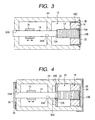
- the weight member 18 may be affixed to the fixing frame 24 at the outside face 18D of the weight member 18 as shown in FIG. 3. In this case, a gap between the outside face 18D of the weight member 18 and the fixing frame 24 may be filled with a resilient adhesive agent 30.
- the actuator 10 is supported at the weight member 18 side in the above-described embodiment, the supporting method of the actuator 10 is not limited thereto.
- the actuator 10 may be supported at the end face 12A side of the piezoelectric element 12.
- a supporting member 32 is affixed to the end face 12A of the piezoelectric element 12.
- a hole 32A is formed in the supporting member 32, and a driving shaft 14 is inserted into the hole 32A.
- the supporting member 32 is fixed with an adhesive agent in a state that it is brought into contact with the stepped portion 24B of the fixing frame 24.
- the actuator 10 supportedasdescribedabove is supportednearly in a state that it is suspended in midair. Therefore, vibration is hardly transmitted between the actuator 10 and the fixing frame 24, wherein influence due to resonance is reduced, and the driven member 16 can be accurately moved.
- a protection plate 26 is mounted onto one side of the fixing frame 24 in FIG. 4 and another protection plate 34 is mounted onto the other side thereof.
- the protection plate 26 is formed to be like a plate and is mounted onto the fixing frame 24 by a double-sided tape 28 in a state that it is in contact with the tip end face of the driving shaft 14.
- the protection plate 34 is composed of metal or resin, etc., and is formed to be an overturned U-shape, and it is mounted in a state that it is not in contact with the weight member 18.
- the actuator 10 is reinforced by attaching the protection plates 26 and 34 to the fixing frame 24, wherein the actuator 10 is prevented from being damaged upon receiving a shock due to a falling object, etc.
- the protection plate 26 may be mounted without contacting with the driving shaft 14. Also, the protection plate 34 may be mounted in contact with the weight member 18.
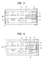
- FIG. 5 is a configurational view showing another supporting method of the actuator 10.
- the actuator 10 shown in FIG. 5 is supported in a state that it is pushed by a pair of supporting plates 40 and 42 at both sides in the extension/contraction direction of the piezoelectric element 12.
- the supporting plate 40 is composed of a thin metal plate and is formed to be an overturned U-shape, and is mounted onto the fixing frame 24 in a state that it is pushed by the weight member 18.
- the supporting plate 42 is composed of a thin metal plate and is affixed to the fixing frame 24 by an adhesive agent 44 in a state that the supporting plate presses the tip end face of the driving shaft 14.
- the actuator 10 If the actuator 10 constructed as described above is supported, the actuator 10 is supported nearly in an internally floated state.
- the actuator 10 supported in such a state has no portion affixed to the fixing frame 24, vibration is hardly transmitted between the actuator 10 and the fixing frame 24, wherein resonance hardly occurs between the actuator 10 and the fixing frame 24. Therefore, since the actuator 10 is supported so that influence due to resonance is reduced, the drivenmember 16 canbe accuratelymoved.
- the actuator 10 can be kept in a resonance-free state by placing the actuator between both sides of the fixing frame 24 and supporting the same therein.
- the actuator 10 may be supported as shown in FIG. 6.
- the actuator 10 in FIG. 6 is supported in a state that both sides of the piezoelectric element 12 are pushed by a pair of supporting members 36 and 36.
- the supporting members 36 and 36 are made of metal, resin or rubber, etc., and are mounted onto the fixing frame 24. Furthermore, the tip ends of the supporting member 36 and 36 and the sides of the piezoelectric element 12 may be adhered with a resilient adhesive agent. Also, by using a cylindrical member instead of a pair of supporting members 36 and 36, the piezoelectric member 12 may be supported at the entire circumference of the side thereof so as to be pushed.
- the actuator 10 supported as described above is supported so that both sides of the piezoelectric element 12 are pushed by a pair of supporting members 36 and 36, the actuator 10 is supported nearly in an internally floated state. Therefore, since vibrations are hardly transmitted between the actuator 10 and the fixing frame 24, the actuator 10 is less influenced due to resonance, and it is possible to accurately move the driven member 16.
- the weight member 18 composed of a soft material is used in the above-described embodiment, the material thereof is not limited thereto. A weight member made of a hard material may be employed. Also in this case, by supporting the actuator 10 as described above, influence due to resonance can be reduced, wherein it is possible to accurately move the driven member 16.
- the weight member 18 is made into a cylindrical shape in the above-described embodiment, the shape thereof is not limited thereto.
- the weight material 18 may be divided into a plurality of pieces to be mounted.
- the actuator 10 according to the present invention may be applicable to a small-sized precision apparatus such as, for example, a digital camera and a mobile telephone.
- a mobile telephone operates at a low voltage that is 3V or less, it is possible to drive the same at a high frequency, which is 20kHz or so, if the actuator 10 according to the present actuator is used, and it is possible to move the driven member 16 at a high speed that is 2mm per second or more. Therefore, even a zoom lens for which movement of 10mm or so is required can be quickly moved.
- the use of the actuator 10 according to the present invention is not limited to movement of a movable lens such as a focus lens, zoom lens, etc., and the actuator 10 may also be used for movement of a CCD.
- the actuator according to the present invention since at least a part of the weight member is disposed inside the end face of an electro-mechanical conversion element, it is possible to downsize the actuator in the driving direction.
Landscapes
- General Electrical Machinery Utilizing Piezoelectricity, Electrostriction Or Magnetostriction (AREA)
Abstract
Description
- The present invention relates to an actuator, and in particular relates to an actuator for driving a lens of a digital camera and a mobile telephone with a camera feature.
- An actuator employing a piezoelectric element has been known as a driving device for a lens of a digital camera. For example, an actuator according to
JP-A-2002-142470 - The thus composed actuator generates a problem of resonating among the pedestal base, the piezoelectric element, and the driving member. Further, the actuator according to
JP-A-2002-142470 - If such resonance is utilized, there is an advantage by which the amount of movement of the drivingmember is increased. For example,
Japanese Patent No. 3171187 - However, since the actuator according to
JP-A-2002-142470 Japanese Patent No. 3171187 - Further, since the actuator according to
JP-A-2002-142470 Japanese Patent No. 3171187 member 2 is displaced in directions other than the extension/contraction direction upon receiving influence of resonance. Therefore, a driving force based on extension and contraction of thepiezoelectric element 1 is not accurately transmitted to the drivenmember 3, wherein it becomes difficult to accurately cause the drivenmember 3 to move in the extension/contraction direction of thepiezoelectric element 1. In particular, if the pedestal base (weight member) is made large to increase the thrust of the drivenmember 3, resonance is liable to occur, wherein an actuator in which resonance is hardly brought about is demanded. - The present invention has been made in view of these circumstances, and an obj ect thereof is to provide an actuator capable of securely obtaining a sufficient thrust of the driven member and capable of being downsized in the driving direction.
- In order to achieve the object, an actuator of a first aspect of the invention comprises: an electro-mechanical conversion element; a driving frictional member mounted onto one side in an extension/contraction direction of the electro-mechanical conversion element, the driving frictional member being frictionally engaged with a driven member; and a weight member mounted onto the other side in the extension/contraction direction of the electro-mechanical conversion element, wherein at least a part of the weight member is disposed at the one side from an end face of the other side of the electro-mechanical conversion element.
- According to the first aspect of the invention, since at least a part of the weight member is disposed at the one side from the end face of the other side of the electro-mechanical conversion element, it is possible to downsize the actuator in the driving direction (that is, in the extension/contraction direction of the electro-mechanical conversion element).
- In addition, according to the first aspect of the invention, since the weight member can be made large without making the actuator large in the driving direction, it is possible to secure a sufficient thrust of the driven member.
- A second aspect of the invention provides the actuator according to the first aspect of the invention, further comprises a connecting member mounted onto the end face of the other side of the electro-mechanical conversion element, wherein the weight member is mounted onto the connecting member.
- According to the second aspect of the invention, since the weight member is mounted onto the end face at the other side of the electro-mechanical conversion element via the connectingmember, the degree of freedom for disposing the weight member is increased, wherein it is possible to further downsize the actuator.
- A third aspect of the invention provides the actuator according to the first or second aspect of the invention, wherein the weight member is formed to be cylindrical, and at least a part of the electro-mechanical conversion element is disposed inside the weight member.
- According to the third aspect of the invention, since the weight member is formed to be cylindrical, it is possible to further downsize the actuator.
-
- FIG. 1 is a sectional view showing an embodiment of an actuator according to the present invention;
- FIGS. 2A and 2B are waveform diagrams showing a driving pulse applied to a piezoelectric element;
- FIG. 3 is a sectional view showing an actuator in which the supporting method differs from that in FIG. 1;
- FIG. 4 is a sectional view showing an actuator in which the supporting method differs from that in FIG. 1;
- FIG. 5 is a sectional view showing an actuator in which the supporting method differs from that in FIG. 1;
- FIG. 6 is a sectional view showing an actuator in which the supporting method differs from that in FIG. 1; and
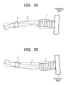
- FIGS. 7A and 7B are views describing problematic points of the related-art actuator.
- Hereinafter, a detailed description is given of a preferred embodiment of an actuator according to the present invention with reference to the accompanying drawings. FIG. 1 is a configurational view depicting an actuator according to the present invention.
- As depicted in FIG. 1, the
actuator 10 is mainly composed of a piezoelectric element (corresponding to an electro-mechanical conversion element) 12, a driving shaft (corresponding to a driving frictional member) 14, a drivenmember 16 and aweight member 18. - The
piezoelectric element 12 is laminated in the direction of the arrow and is formed to be like a rectangular parallelepiped. Thepiezoelectric element 12 is deformed (is caused to extend and contract) in the lamination direction by applying voltage thereto. Therefore, thepiezoelectric element 12 is devised so that the end faces 12A and 12B in its longitudinal direction are displaced. - The base end of the
driving shaft 14 is affixed to oneend face 12A of theend faces piezoelectric element 12. Thedriving shaft 14 is formed to be, for example, columnar, and the axis is disposed in the directions of the arrow (that is, in the extension/contraction direction of the piezoelectricelement). A graphite crystal composite in which graphite crystal is firmly compounded), for example, carbon graphite is employed as the material of thedriving shaft 14. In addition, thedriving shaft 14 is not limited to a columnar shape. It may be a square rod. - The driven
member 16 is a member connected to a lens frame (not shown), and is engaged with thedriving shaft 14 with a predetermined frictional force. Further, the drivenmember 16 is slidably supported along thedriving shaft 14. The frictional force between the drivenmember 16 and thedriving shaft 14 is set so that, when a gently fluctuating voltage is applied to thepiezoelectric element 12, the static frictional force is made greater than the driving force, and when a radically fluctuating voltage is applied to thepiezoelectric element 12, the static frictional force is made smaller than the driving force. - The
weight member 18 is formed to be rectangularly tubular, wherein arectangular hole 18 that is greater than the section of thepiezoelectric element 12 is formed. In a state that theweight member 18 is inserted into thehole 18, theface 18B at the base end side of theweight member 18 is affixed to the plate-shaped connectingmember 22 with an adhesive agent, and the connectingmember 22 is affixed to theend face 12B of thepiezoelectric element 12 with a resilientadhesive agent 20. Accordingly, theweight member 18 is mounted onto theend face 12B of thepiezoelectric element 12 via the connectingmember 22, and theweight member 18 is disposed at theend face 12A side from theend face 12B of thepiezoelectric element 12. - The
weight member 18 prevents theend face 12B from being displaced greater than theend face 12A by applying a load to theend face 12B of thepiezoelectric element 12. It is preferable that the weight of theweight member 18 is greater than that of the drivingshaft 14. For example, where the weight of the drivingshaft 14 is 8mg, and the weight of thepiezoelectric element 12 is 32mg, theweight member 18 of 32mg is used. - Also, the
weight member 18 is formed of a soft material. A material whose Young's modulus is smaller than that of thepiezoelectric element 12 and the drivingshaft 14 is used as the material of theweight member 18. It is preferable that the Young's modulus of theweight member 18 is 1Gpa or less, and further preferably, the Young's modulus is 300Mpa or less. Such aweight member 18 is formed by blending a resilient body such as rubber with metal powder having a high specific gravity. For example, theweight member 18 is produced by blending urethane rubber or urethane resin with tungsten powder. It is preferable that the specific gravity of theweight member 18 is as high as possible in view of downsizing of the unit, and the specific gravity thereof is set to, for example, approximately 8 through 12. - The
weight member 18 is fixed at the fixingframe 24 at theface 18C at the tip end side with an adhesive agent, thereby theactuator 10 composed of theweight member 18, connectingmember 22,piezoelectric member 12, and drivingshaft 14 is supported on the fixingframe 24. The fixingframe 24 is a member mounted onto the main body (not shown) of a mobile telephone and is provided with two throughholes holes shaft 14, wherein the drivingshaft 14 is slidably supported in the direction of the arrows by inserting the drivingshaft 14 into the throughholes - A driving pulse supplying device (not shown) is electrically connected to the above-described
piezoelectric element 12, and voltage having such waveforms as shown in FIG. 2A and FIG. 2B is applied by the driving pulse supplying device. - FIG. 2A and FIG. 2B show examples of pulse waveforms applied to the
piezoelectric element 12, wherein FIG. 2Ashowsapulsewaveform for causing the drivenmember 16 to move in the left direction of the arrows, and FIG. 2B shows a pulse waveform for causing the drivenmember 16 to move in the right direction of the arrows. - In the case of FIG. 2A, a roughly comb-shaped driving pulse in which a gradual rise occurs from time α1 to time α2, and a rapid fall occurs at time α3 is applied to the
piezoelectric element 12. Therefore, thepiezoelectric element 12 gently extends from time α1 to time α2. At this time, since the drivingshaft 14 gradually moves, the drivenmember 16 moves along with the drivingshaft 14. Accordingly, the drivenmember 16 can be moved in the left direction in FIG. 1. Since thepiezoelectric element 12 rapidly contracts at time α3, the drivingshaft 14 moves in the right direction in FIG. 1. At this time, since the drivingshaft 14 rapidly moves, only the drivingshaft 14 moves with the drivenmember 16 remaining stopped at its position by inertia. Therefore, by repeatedly applying a comb-shaped driving pulse shown in FIG. 2A, the drivenmember 16 shown in FIG. 1 repeats moving in the left direction and stopping, wherein it is possible to move the drivenmember 16 in the left direction. - In the case of FIG. 2B, a roughly comb-shaped driving pulse in which a rapid rise occurs at time β1 and a gradual fall occurs from time β2 to β3 is applied to the
piezoelectric element 12. Therefore, thepiezoelectric element 12 rapidly extends at time β1, wherein the drivingshaft 14 moves in the left direction in FIG. 1. At this time, since the drivingshaft 14 rapidly moves, only the drivingshaft 14 moves with the drivenmember 16 remaining stopped at its position by inertia. Thepiezoelectric element 12 gradually contracts from time β2 to time β3. At this time, since the drivingshaft 14 is gently displaced, the drivenmember 16 moves along with the drivingshaft 14. The drivenmember 16 can thus be moved in the right direction in FIG. 1. Therefore, by repeatedly applying the comb-shaped driving pulse shown in FIG. 2B, the drivenmember 16 shown in FIG. 1 repeats moving in the right direction and stopping, wherein the drivenmember 16 can be moved in the right direction. - Since, in the
actuator 10 according to the embodiment constructed as described above, theweight member 18 is displaced at the end face 12A side from theend face 12B of thepiezoelectric element 12, it is possible to downsize theactuator 10 in the driving direction in comparison with the related-art unit shown in FIGS. 7A and 7B (that is, the case where thepiezoelectric element 1, drivingshaft 2 and pedestal base are arranged in the driving direction). - Further, since the
actuator 10 according to the embodiment employs a soft material as theweight member 18, it is possible to suppress resonance generated in theactuator 10 itself. That is, where theweight member 18 composed of a soft material is used, the resonance frequency of the system consisting of thepiezoelectric element 12, drivingshaft 14, andweight member 18 can be lowered. In detail, it is possible to greatly lower the resonance frequency f0 of theequivalence 1 free system in which thepiezoelectric element 12 and the drivingshaft 14 are made into mass and theweight member 18 is made into a resilient body. Since the resonance frequency f0 is lowered, the driving frequency f is easily set to a vibration-proof region in which f≥21/2·f0 is brought about, wherein influence of the resonance can be reduced. Therefore, as shown in FIG. 7A and FIG. 7B, it is possible to prevent vibrations of thepiezoelectric element 12 in directions other than the extension/contraction direction, which are generated where theweight member 18 is composed of a hard material. Thereby, since the drivingshaft 14 is displaced in the extension/contraction direction of thepiezoelectric element 12, a driving force based on extension and contraction of thepiezoelectric element 12 can be accurately transmitted to the drivenmember 16, wherein it is possible to accurately drive and control the drivenmember 16 in the extension/contraction direction of thepiezoelectric element 12. In addition, since the resonance frequency f0 is lowered, influence due to unevenness in the composition of thepiezoelectric element 12, drivingshaft 14 andweight member 18 is reduced, wherein a stable driving force can be brought about. - Since resonance inside the
actuator 10 can be suppressed by thus using theweight member 18 of a soft material, influence of the resonance is reduced where alarge weight member 18 is employed, wherein the drivenmember 16 can be further accurately moved. - Although the entirety of the
weight member 18 is disposed at the end face 12A side from theend face 12B of thepiezoelectric element 12 in the above-described embodiment, the position of disposing theweight member 18 is not limited thereto. For example, only a part of theweight member 18 may be disposed at the end face 12A side from theend face 12B. - Further, although the
weight member 18 is affixed to the fixingframe 24 at the tipend side face 18C in the above-described embodiment, the fixing position thereof is not limited thereto. Theweight member 18 may be affixed to the fixingframe 24 at theoutside face 18D of theweight member 18 as shown in FIG. 3. In this case, a gap between theoutside face 18D of theweight member 18 and the fixingframe 24 may be filled with a resilientadhesive agent 30. - In addition, although the
actuator 10 is supported at theweight member 18 side in the above-described embodiment, the supporting method of theactuator 10 is not limited thereto. For example, as shown in FIG. 4, theactuator 10 may be supported at the end face 12A side of thepiezoelectric element 12. In theactuator 10 shown in FIG. 4, a supportingmember 32 is affixed to theend face 12A of thepiezoelectric element 12. Ahole 32A is formed in the supportingmember 32, and a drivingshaft 14 is inserted into thehole 32A. Also, the supportingmember 32 is fixed with an adhesive agent in a state that it is brought into contact with the steppedportion 24B of the fixingframe 24. - The
actuator 10 supportedasdescribedabove is supportednearly in a state that it is suspended in midair. Therefore, vibration is hardly transmitted between the actuator 10 and the fixingframe 24, wherein influence due to resonance is reduced, and the drivenmember 16 can be accurately moved. - Also, a
protection plate 26 is mounted onto one side of the fixingframe 24 in FIG. 4 and anotherprotection plate 34 is mounted onto the other side thereof. Theprotection plate 26 is formed to be like a plate and is mounted onto the fixingframe 24 by a double-sided tape 28 in a state that it is in contact with the tip end face of the drivingshaft 14. Theprotection plate 34 is composed of metal or resin, etc., and is formed to be an overturned U-shape, and it is mounted in a state that it is not in contact with theweight member 18. Theactuator 10 is reinforced by attaching theprotection plates frame 24, wherein theactuator 10 is prevented from being damaged upon receiving a shock due to a falling object, etc. Theprotection plate 26 may be mounted without contacting with the drivingshaft 14. Also, theprotection plate 34 may be mounted in contact with theweight member 18. - FIG. 5 is a configurational view showing another supporting method of the
actuator 10. Theactuator 10 shown in FIG. 5 is supported in a state that it is pushed by a pair of supportingplates piezoelectric element 12. The supportingplate 40 is composed of a thin metal plate and is formed to be an overturned U-shape, and is mounted onto the fixingframe 24 in a state that it is pushed by theweight member 18. The supportingplate 42 is composed of a thin metal plate and is affixed to the fixingframe 24 by anadhesive agent 44 in a state that the supporting plate presses the tip end face of the drivingshaft 14. - If the
actuator 10 constructed as described above is supported, theactuator 10 is supported nearly in an internally floated state. Theactuator 10 supported in such a state has no portion affixed to the fixingframe 24, vibration is hardly transmitted between the actuator 10 and the fixingframe 24, wherein resonance hardly occurs between the actuator 10 and the fixingframe 24. Therefore, since theactuator 10 is supported so that influence due to resonance is reduced, thedrivenmember 16 canbe accuratelymoved. Inparticular, where theweight member 18 is composed of a soft material, since resonance is hardly brought about inside theactuator 10 as described above, theactuator 10 can be kept in a resonance-free state by placing the actuator between both sides of the fixingframe 24 and supporting the same therein. - Also, the
actuator 10 may be supported as shown in FIG. 6. Theactuator 10 in FIG. 6 is supported in a state that both sides of thepiezoelectric element 12 are pushed by a pair of supportingmembers members frame 24. Furthermore, the tip ends of the supportingmember piezoelectric element 12 may be adhered with a resilient adhesive agent. Also, by using a cylindrical member instead of a pair of supportingmembers piezoelectric member 12 may be supported at the entire circumference of the side thereof so as to be pushed. - Since the
actuator 10 supported as described above is supported so that both sides of thepiezoelectric element 12 are pushed by a pair of supportingmembers actuator 10 is supported nearly in an internally floated state. Therefore, since vibrations are hardly transmitted between the actuator 10 and the fixingframe 24, theactuator 10 is less influenced due to resonance, and it is possible to accurately move the drivenmember 16. - Although the
weight member 18 composed of a soft material is used in the above-described embodiment, the material thereof is not limited thereto. A weight member made of a hard material may be employed. Also in this case, by supporting theactuator 10 as described above, influence due to resonance can be reduced, wherein it is possible to accurately move the drivenmember 16. - Although the
weight member 18 is made into a cylindrical shape in the above-described embodiment, the shape thereof is not limited thereto. Theweight material 18 may be divided into a plurality of pieces to be mounted. - Also, the
actuator 10 according to the present invention may be applicable to a small-sized precision apparatus such as, for example, a digital camera and a mobile telephone. In particular, although it is necessary that a mobile telephone operates at a low voltage that is 3V or less, it is possible to drive the same at a high frequency, which is 20kHz or so, if theactuator 10 according to the present actuator is used, and it is possible to move the drivenmember 16 at a high speed that is 2mm per second or more. Therefore, even a zoom lens for which movement of 10mm or so is required can be quickly moved. Also, the use of theactuator 10 according to the present invention is not limited to movement of a movable lens such as a focus lens, zoom lens, etc., and theactuator 10 may also be used for movement of a CCD. - With the actuator according to the present invention, since at least a part of the weight member is disposed inside the end face of an electro-mechanical conversion element, it is possible to downsize the actuator in the driving direction.
- The entire disclosure of each and every foreign patent application from which the benefit of foreign priority has been claimed in the present application is incorporated herein by reference, as if fully set forth.
Claims (3)
- An actuator comprising:an electro-mechanical conversion element;a driving frictional member mounted onto one side in an extension/contraction direction of the electro-mechanical conversion element, the driving frictional member being frictionally engaged with a driven member; anda weight member mounted onto the other side in the extension/contraction direction of the electro-mechanical conversion element,wherein at least a part of the weight member is disposed at the one side from an end face of the other side of the electro-mechanical conversion element.
- The actuator according to Claim 1, further comprisinga connecting member mounted onto the end face of the other side of the electro-mechanical conversion element,wherein the weight member is mounted onto the connecting member.
- The actuator according to Claim 1,wherein the weight member is formed to be cylindrical, andat least a part of the electro-mechanical conversion element is disposed inside the weight member.
Applications Claiming Priority (1)
| Application Number | Priority Date | Filing Date | Title |
|---|---|---|---|
| JP2005288633A JP2007104761A (en) | 2005-09-30 | 2005-09-30 | Actuator |
Publications (2)
| Publication Number | Publication Date |
|---|---|
| EP1770420A1 true EP1770420A1 (en) | 2007-04-04 |
| EP1770420B1 EP1770420B1 (en) | 2012-05-23 |
Family
ID=37649385
Family Applications (1)
| Application Number | Title | Priority Date | Filing Date |
|---|---|---|---|
| EP06020528A Not-in-force EP1770420B1 (en) | 2005-09-30 | 2006-09-29 | Actuator |
Country Status (4)
| Country | Link |
|---|---|
| US (1) | US7368854B2 (en) |
| EP (1) | EP1770420B1 (en) |
| JP (1) | JP2007104761A (en) |
| CN (1) | CN1941595B (en) |
Families Citing this family (17)
| Publication number | Priority date | Publication date | Assignee | Title |
|---|---|---|---|---|
| JP2007274777A (en) * | 2006-03-30 | 2007-10-18 | Fujinon Corp | Piezoelectric element and driving device |
| JP4879641B2 (en) * | 2006-04-28 | 2012-02-22 | パナソニック株式会社 | Piezoelectric driving device, imaging device, and portable terminal device |
| EP2006994A4 (en) | 2006-04-10 | 2012-11-07 | Panasonic Corp | PIEZOELECTRIC ATTACK DEVICE, IMAGE FORMING DEVICE, AND MOBILE TERMINAL DEVICE |
| JP4898264B2 (en) * | 2006-04-10 | 2012-03-14 | パナソニック株式会社 | Piezoelectric driving device, imaging device, and portable terminal device |
| JP5146325B2 (en) * | 2007-01-10 | 2013-02-20 | コニカミノルタアドバンストレイヤー株式会社 | Drive device |
| KR20080093880A (en) * | 2007-04-17 | 2008-10-22 | 미쓰미덴기가부시기가이샤 | drive |
| KR20080093885A (en) * | 2007-04-18 | 2008-10-22 | 미쓰미덴기가부시기가이샤 | drive |
| KR20080094572A (en) * | 2007-04-19 | 2008-10-23 | 미쓰미덴기가부시기가이샤 | drive |
| US7956513B2 (en) * | 2007-04-20 | 2011-06-07 | Mitsumi Electric Co., Ltd. | Method of driving a driving device |
| US7759634B2 (en) * | 2007-04-24 | 2010-07-20 | Mitsumi Electric Co., Ltd. | Position detecting device capable of improving detection accuracy |
| KR100975137B1 (en) * | 2008-05-02 | 2010-08-11 | 한국생산기술연구원 | High Rigidity Dual Servo Nanostage |
| US8829766B2 (en) * | 2008-08-01 | 2014-09-09 | Epcos Ag | Piezoelectric resonator operating in thickness shear mode |
| JP2010246277A (en) * | 2009-04-07 | 2010-10-28 | Shicoh Engineering Co Ltd | Linear drive unit |
| JP6330129B2 (en) * | 2014-06-23 | 2018-05-30 | 新シコー科技株式会社 | LINEAR DRIVE DEVICE, ELECTRONIC DEVICE USING LINEAR DRIVE DEVICE AND BODY |
| JP6736371B2 (en) * | 2016-06-17 | 2020-08-05 | キヤノン株式会社 | Position adjusting mechanism, exposure apparatus, and article manufacturing method |
| JP6819274B2 (en) * | 2016-12-21 | 2021-01-27 | Tdk株式会社 | Piezoelectric unit |
| JP6812510B2 (en) * | 2018-08-09 | 2021-01-13 | キヤノン株式会社 | Vibration type actuator and electronic equipment having it |
Citations (4)
| Publication number | Priority date | Publication date | Assignee | Title |
|---|---|---|---|---|
| US20020030422A1 (en) * | 2000-09-14 | 2002-03-14 | Minolta Co., Ltd. | Drive mechanism employing electromechanical transducer |
| US20030168940A1 (en) * | 2002-01-10 | 2003-09-11 | Kazuhito Kurita | Drive unit |
| US20040012304A1 (en) * | 2001-01-22 | 2004-01-22 | Ryuichi Yoshida | Drive mechanism employing electromechanical transducer and method for controlling the drive mechanism |
| EP1708287A2 (en) * | 2005-03-31 | 2006-10-04 | Fujinon Corporation | Driving mechanism |
Family Cites Families (8)
| Publication number | Priority date | Publication date | Assignee | Title |
|---|---|---|---|---|
| JPS5831159B2 (en) * | 1978-09-29 | 1983-07-04 | 松下電工株式会社 | Ultrasonic transducer device |
| JPH09247967A (en) * | 1996-03-06 | 1997-09-19 | Minolta Co Ltd | Driving device using electromechanical transducer |
| US5912525A (en) * | 1996-03-21 | 1999-06-15 | Nikon Corporation | Vibration actuator |
| JPH10337057A (en) * | 1997-06-02 | 1998-12-18 | Minolta Co Ltd | Drive |
| JP2002119074A (en) * | 2000-10-04 | 2002-04-19 | Minolta Co Ltd | Driving device using electromechanical transducer |
| US6611080B2 (en) * | 2001-06-04 | 2003-08-26 | Nanyang Technological University | Linear piezoelectric motor with self locking means |
| KR100501196B1 (en) * | 2003-07-09 | 2005-07-18 | 삼성전기주식회사 | lens driving device |
| JP2007151238A (en) * | 2005-11-24 | 2007-06-14 | Fujinon Corp | Drive device |
-
2005
- 2005-09-30 JP JP2005288633A patent/JP2007104761A/en not_active Abandoned
-
2006
- 2006-09-26 CN CN200610139611XA patent/CN1941595B/en not_active Expired - Fee Related
- 2006-09-28 US US11/528,455 patent/US7368854B2/en not_active Expired - Fee Related
- 2006-09-29 EP EP06020528A patent/EP1770420B1/en not_active Not-in-force
Patent Citations (4)
| Publication number | Priority date | Publication date | Assignee | Title |
|---|---|---|---|---|
| US20020030422A1 (en) * | 2000-09-14 | 2002-03-14 | Minolta Co., Ltd. | Drive mechanism employing electromechanical transducer |
| US20040012304A1 (en) * | 2001-01-22 | 2004-01-22 | Ryuichi Yoshida | Drive mechanism employing electromechanical transducer and method for controlling the drive mechanism |
| US20030168940A1 (en) * | 2002-01-10 | 2003-09-11 | Kazuhito Kurita | Drive unit |
| EP1708287A2 (en) * | 2005-03-31 | 2006-10-04 | Fujinon Corporation | Driving mechanism |
Also Published As
| Publication number | Publication date |
|---|---|
| JP2007104761A (en) | 2007-04-19 |
| CN1941595B (en) | 2010-11-10 |
| US7368854B2 (en) | 2008-05-06 |
| CN1941595A (en) | 2007-04-04 |
| EP1770420B1 (en) | 2012-05-23 |
| US20070075609A1 (en) | 2007-04-05 |
Similar Documents
| Publication | Publication Date | Title |
|---|---|---|
| EP1770420B1 (en) | Actuator | |
| EP1788643B1 (en) | Driving mechanism | |
| US7372190B2 (en) | Driving apparatus | |
| KR100777630B1 (en) | Driving machanism | |
| US20110095649A1 (en) | Vibrating device | |
| KR100777634B1 (en) | Driving mechanism | |
| KR100777637B1 (en) | Driving mechanism, photographic mechanism and cellular phone | |
| CN101860258B (en) | Linear drive unit | |
| EP1753042B1 (en) | Actuator | |
| CN102062927A (en) | Linear driving device | |
| KR100777636B1 (en) | Driving mechanism, imaging mechanism and cellular phone | |
| JP2008245467A (en) | Drive device | |
| EP1753121A2 (en) | Actuator | |
| CN100529827C (en) | Driving mechanism, photographic mechanism and cellular phone | |
| CN100533194C (en) | drive unit | |
| JP6948102B2 (en) | Linear drive, camera and electronic equipment | |
| CN100456072C (en) | drive unit | |
| JP2007274788A (en) | Drive unit | |
| JP2007274816A (en) | Drive unit | |
| JP2007274758A (en) | Drive unit |
Legal Events
| Date | Code | Title | Description |
|---|---|---|---|
| PUAI | Public reference made under article 153(3) epc to a published international application that has entered the european phase |
Free format text: ORIGINAL CODE: 0009012 |
|
| 17P | Request for examination filed |
Effective date: 20060929 |
|
| AK | Designated contracting states |
Kind code of ref document: A1 Designated state(s): AT BE BG CH CY CZ DE DK EE ES FI FR GB GR HU IE IS IT LI LT LU LV MC NL PL PT RO SE SI SK TR |
|
| AX | Request for extension of the european patent |
Extension state: AL BA HR MK YU |
|
| AKX | Designation fees paid |
Designated state(s): AT BE BG CH CY CZ DE DK EE ES FI FR GB GR HU IE IS IT LI LT LU LV MC NL PL PT RO SE SI SK TR |
|
| RAP1 | Party data changed (applicant data changed or rights of an application transferred) |
Owner name: FUJIFILM CORPORATION |
|
| GRAP | Despatch of communication of intention to grant a patent |
Free format text: ORIGINAL CODE: EPIDOSNIGR1 |
|
| GRAS | Grant fee paid |
Free format text: ORIGINAL CODE: EPIDOSNIGR3 |
|
| GRAA | (expected) grant |
Free format text: ORIGINAL CODE: 0009210 |
|
| AK | Designated contracting states |
Kind code of ref document: B1 Designated state(s): AT BE BG CH CY CZ DE DK EE ES FI FR GB GR HU IE IS IT LI LT LU LV MC NL PL PT RO SE SI SK TR |
|
| REG | Reference to a national code |
Ref country code: GB Ref legal event code: FG4D |
|
| REG | Reference to a national code |
Ref country code: CH Ref legal event code: EP |
|
| REG | Reference to a national code |
Ref country code: AT Ref legal event code: REF Ref document number: 559331 Country of ref document: AT Kind code of ref document: T Effective date: 20120615 |
|
| REG | Reference to a national code |
Ref country code: IE Ref legal event code: FG4D |
|
| REG | Reference to a national code |
Ref country code: DE Ref legal event code: R096 Ref document number: 602006029618 Country of ref document: DE Effective date: 20120719 |
|
| REG | Reference to a national code |
Ref country code: NL Ref legal event code: VDEP Effective date: 20120523 |
|
| REG | Reference to a national code |
Ref country code: LT Ref legal event code: MG4D Effective date: 20120523 |
|
| PG25 | Lapsed in a contracting state [announced via postgrant information from national office to epo] |
Ref country code: LT Free format text: LAPSE BECAUSE OF FAILURE TO SUBMIT A TRANSLATION OF THE DESCRIPTION OR TO PAY THE FEE WITHIN THE PRESCRIBED TIME-LIMIT Effective date: 20120523 Ref country code: FI Free format text: LAPSE BECAUSE OF FAILURE TO SUBMIT A TRANSLATION OF THE DESCRIPTION OR TO PAY THE FEE WITHIN THE PRESCRIBED TIME-LIMIT Effective date: 20120523 Ref country code: IS Free format text: LAPSE BECAUSE OF FAILURE TO SUBMIT A TRANSLATION OF THE DESCRIPTION OR TO PAY THE FEE WITHIN THE PRESCRIBED TIME-LIMIT Effective date: 20120923 Ref country code: CY Free format text: LAPSE BECAUSE OF FAILURE TO SUBMIT A TRANSLATION OF THE DESCRIPTION OR TO PAY THE FEE WITHIN THE PRESCRIBED TIME-LIMIT Effective date: 20120523 Ref country code: SE Free format text: LAPSE BECAUSE OF FAILURE TO SUBMIT A TRANSLATION OF THE DESCRIPTION OR TO PAY THE FEE WITHIN THE PRESCRIBED TIME-LIMIT Effective date: 20120523 |
|
| PGFP | Annual fee paid to national office [announced via postgrant information from national office to epo] |
Ref country code: GB Payment date: 20120925 Year of fee payment: 7 |
|
| REG | Reference to a national code |
Ref country code: AT Ref legal event code: MK05 Ref document number: 559331 Country of ref document: AT Kind code of ref document: T Effective date: 20120523 |
|
| PG25 | Lapsed in a contracting state [announced via postgrant information from national office to epo] |
Ref country code: SI Free format text: LAPSE BECAUSE OF FAILURE TO SUBMIT A TRANSLATION OF THE DESCRIPTION OR TO PAY THE FEE WITHIN THE PRESCRIBED TIME-LIMIT Effective date: 20120523 Ref country code: PT Free format text: LAPSE BECAUSE OF FAILURE TO SUBMIT A TRANSLATION OF THE DESCRIPTION OR TO PAY THE FEE WITHIN THE PRESCRIBED TIME-LIMIT Effective date: 20120924 Ref country code: GR Free format text: LAPSE BECAUSE OF FAILURE TO SUBMIT A TRANSLATION OF THE DESCRIPTION OR TO PAY THE FEE WITHIN THE PRESCRIBED TIME-LIMIT Effective date: 20120824 Ref country code: LV Free format text: LAPSE BECAUSE OF FAILURE TO SUBMIT A TRANSLATION OF THE DESCRIPTION OR TO PAY THE FEE WITHIN THE PRESCRIBED TIME-LIMIT Effective date: 20120523 |
|
| PG25 | Lapsed in a contracting state [announced via postgrant information from national office to epo] |
Ref country code: BE Free format text: LAPSE BECAUSE OF FAILURE TO SUBMIT A TRANSLATION OF THE DESCRIPTION OR TO PAY THE FEE WITHIN THE PRESCRIBED TIME-LIMIT Effective date: 20120523 |
|
| PGFP | Annual fee paid to national office [announced via postgrant information from national office to epo] |
Ref country code: FR Payment date: 20120809 Year of fee payment: 7 |
|
| PG25 | Lapsed in a contracting state [announced via postgrant information from national office to epo] |
Ref country code: SK Free format text: LAPSE BECAUSE OF FAILURE TO SUBMIT A TRANSLATION OF THE DESCRIPTION OR TO PAY THE FEE WITHIN THE PRESCRIBED TIME-LIMIT Effective date: 20120523 Ref country code: AT Free format text: LAPSE BECAUSE OF FAILURE TO SUBMIT A TRANSLATION OF THE DESCRIPTION OR TO PAY THE FEE WITHIN THE PRESCRIBED TIME-LIMIT Effective date: 20120523 Ref country code: RO Free format text: LAPSE BECAUSE OF FAILURE TO SUBMIT A TRANSLATION OF THE DESCRIPTION OR TO PAY THE FEE WITHIN THE PRESCRIBED TIME-LIMIT Effective date: 20120523 Ref country code: CZ Free format text: LAPSE BECAUSE OF FAILURE TO SUBMIT A TRANSLATION OF THE DESCRIPTION OR TO PAY THE FEE WITHIN THE PRESCRIBED TIME-LIMIT Effective date: 20120523 Ref country code: NL Free format text: LAPSE BECAUSE OF FAILURE TO SUBMIT A TRANSLATION OF THE DESCRIPTION OR TO PAY THE FEE WITHIN THE PRESCRIBED TIME-LIMIT Effective date: 20120523 Ref country code: EE Free format text: LAPSE BECAUSE OF FAILURE TO SUBMIT A TRANSLATION OF THE DESCRIPTION OR TO PAY THE FEE WITHIN THE PRESCRIBED TIME-LIMIT Effective date: 20120523 Ref country code: DK Free format text: LAPSE BECAUSE OF FAILURE TO SUBMIT A TRANSLATION OF THE DESCRIPTION OR TO PAY THE FEE WITHIN THE PRESCRIBED TIME-LIMIT Effective date: 20120523 |
|
| PGFP | Annual fee paid to national office [announced via postgrant information from national office to epo] |
Ref country code: DE Payment date: 20121128 Year of fee payment: 7 |
|
| PG25 | Lapsed in a contracting state [announced via postgrant information from national office to epo] |
Ref country code: PL Free format text: LAPSE BECAUSE OF FAILURE TO SUBMIT A TRANSLATION OF THE DESCRIPTION OR TO PAY THE FEE WITHIN THE PRESCRIBED TIME-LIMIT Effective date: 20120523 Ref country code: IT Free format text: LAPSE BECAUSE OF FAILURE TO SUBMIT A TRANSLATION OF THE DESCRIPTION OR TO PAY THE FEE WITHIN THE PRESCRIBED TIME-LIMIT Effective date: 20120523 |
|
| PLBE | No opposition filed within time limit |
Free format text: ORIGINAL CODE: 0009261 |
|
| STAA | Information on the status of an ep patent application or granted ep patent |
Free format text: STATUS: NO OPPOSITION FILED WITHIN TIME LIMIT |
|
| PG25 | Lapsed in a contracting state [announced via postgrant information from national office to epo] |
Ref country code: ES Free format text: LAPSE BECAUSE OF FAILURE TO SUBMIT A TRANSLATION OF THE DESCRIPTION OR TO PAY THE FEE WITHIN THE PRESCRIBED TIME-LIMIT Effective date: 20120903 Ref country code: MC Free format text: LAPSE BECAUSE OF NON-PAYMENT OF DUE FEES Effective date: 20120930 |
|
| REG | Reference to a national code |
Ref country code: CH Ref legal event code: PL |
|
| 26N | No opposition filed |
Effective date: 20130226 |
|
| REG | Reference to a national code |
Ref country code: IE Ref legal event code: MM4A |
|
| REG | Reference to a national code |
Ref country code: DE Ref legal event code: R097 Ref document number: 602006029618 Country of ref document: DE Effective date: 20130226 |
|
| PG25 | Lapsed in a contracting state [announced via postgrant information from national office to epo] |
Ref country code: CH Free format text: LAPSE BECAUSE OF NON-PAYMENT OF DUE FEES Effective date: 20120930 Ref country code: IE Free format text: LAPSE BECAUSE OF NON-PAYMENT OF DUE FEES Effective date: 20120929 Ref country code: LI Free format text: LAPSE BECAUSE OF NON-PAYMENT OF DUE FEES Effective date: 20120930 Ref country code: BG Free format text: LAPSE BECAUSE OF FAILURE TO SUBMIT A TRANSLATION OF THE DESCRIPTION OR TO PAY THE FEE WITHIN THE PRESCRIBED TIME-LIMIT Effective date: 20120823 |
|
| PG25 | Lapsed in a contracting state [announced via postgrant information from national office to epo] |
Ref country code: TR Free format text: LAPSE BECAUSE OF FAILURE TO SUBMIT A TRANSLATION OF THE DESCRIPTION OR TO PAY THE FEE WITHIN THE PRESCRIBED TIME-LIMIT Effective date: 20120523 |
|
| GBPC | Gb: european patent ceased through non-payment of renewal fee |
Effective date: 20130929 |
|
| PG25 | Lapsed in a contracting state [announced via postgrant information from national office to epo] |
Ref country code: LU Free format text: LAPSE BECAUSE OF NON-PAYMENT OF DUE FEES Effective date: 20120929 |
|
| REG | Reference to a national code |
Ref country code: DE Ref legal event code: R119 Ref document number: 602006029618 Country of ref document: DE Effective date: 20140401 |
|
| REG | Reference to a national code |
Ref country code: FR Ref legal event code: ST Effective date: 20140530 |
|
| PG25 | Lapsed in a contracting state [announced via postgrant information from national office to epo] |
Ref country code: HU Free format text: LAPSE BECAUSE OF FAILURE TO SUBMIT A TRANSLATION OF THE DESCRIPTION OR TO PAY THE FEE WITHIN THE PRESCRIBED TIME-LIMIT Effective date: 20060929 Ref country code: GB Free format text: LAPSE BECAUSE OF NON-PAYMENT OF DUE FEES Effective date: 20130929 |
|
| PG25 | Lapsed in a contracting state [announced via postgrant information from national office to epo] |
Ref country code: DE Free format text: LAPSE BECAUSE OF NON-PAYMENT OF DUE FEES Effective date: 20140401 Ref country code: FR Free format text: LAPSE BECAUSE OF NON-PAYMENT OF DUE FEES Effective date: 20130930 |