EP1770258A1 - A method for a variable air intake system and an internal combustion engine comprising a variable air intake system. - Google Patents
A method for a variable air intake system and an internal combustion engine comprising a variable air intake system. Download PDFInfo
- Publication number
- EP1770258A1 EP1770258A1 EP05109144A EP05109144A EP1770258A1 EP 1770258 A1 EP1770258 A1 EP 1770258A1 EP 05109144 A EP05109144 A EP 05109144A EP 05109144 A EP05109144 A EP 05109144A EP 1770258 A1 EP1770258 A1 EP 1770258A1
- Authority
- EP
- European Patent Office
- Prior art keywords
- vol
- air intake
- related parameter
- value
- engine
- Prior art date
- Legal status (The legal status is an assumption and is not a legal conclusion. Google has not performed a legal analysis and makes no representation as to the accuracy of the status listed.)
- Granted
Links
- 238000002485 combustion reaction Methods 0.000 title claims abstract description 20
- 238000000034 method Methods 0.000 title claims abstract description 20
- 230000001419 dependent effect Effects 0.000 claims 3
- 238000010586 diagram Methods 0.000 description 4
- 239000000446 fuel Substances 0.000 description 2
- 238000011144 upstream manufacturing Methods 0.000 description 2
- 238000001514 detection method Methods 0.000 description 1
- 230000007257 malfunction Effects 0.000 description 1
Images





Classifications
-
- F—MECHANICAL ENGINEERING; LIGHTING; HEATING; WEAPONS; BLASTING
- F02—COMBUSTION ENGINES; HOT-GAS OR COMBUSTION-PRODUCT ENGINE PLANTS
- F02D—CONTROLLING COMBUSTION ENGINES
- F02D41/00—Electrical control of supply of combustible mixture or its constituents
- F02D41/22—Safety or indicating devices for abnormal conditions
- F02D41/222—Safety or indicating devices for abnormal conditions relating to the failure of sensors or parameter detection devices
-
- F—MECHANICAL ENGINEERING; LIGHTING; HEATING; WEAPONS; BLASTING
- F02—COMBUSTION ENGINES; HOT-GAS OR COMBUSTION-PRODUCT ENGINE PLANTS
- F02B—INTERNAL-COMBUSTION PISTON ENGINES; COMBUSTION ENGINES IN GENERAL
- F02B27/00—Use of kinetic or wave energy of charge in induction systems, or of combustion residues in exhaust systems, for improving quantity of charge or for increasing removal of combustion residues
- F02B27/02—Use of kinetic or wave energy of charge in induction systems, or of combustion residues in exhaust systems, for improving quantity of charge or for increasing removal of combustion residues the systems having variable, i.e. adjustable, cross-sectional areas, chambers of variable volume, or like variable means
- F02B27/0205—Use of kinetic or wave energy of charge in induction systems, or of combustion residues in exhaust systems, for improving quantity of charge or for increasing removal of combustion residues the systems having variable, i.e. adjustable, cross-sectional areas, chambers of variable volume, or like variable means characterised by the charging effect
- F02B27/021—Resonance charging
-
- F—MECHANICAL ENGINEERING; LIGHTING; HEATING; WEAPONS; BLASTING
- F02—COMBUSTION ENGINES; HOT-GAS OR COMBUSTION-PRODUCT ENGINE PLANTS
- F02B—INTERNAL-COMBUSTION PISTON ENGINES; COMBUSTION ENGINES IN GENERAL
- F02B27/00—Use of kinetic or wave energy of charge in induction systems, or of combustion residues in exhaust systems, for improving quantity of charge or for increasing removal of combustion residues
- F02B27/02—Use of kinetic or wave energy of charge in induction systems, or of combustion residues in exhaust systems, for improving quantity of charge or for increasing removal of combustion residues the systems having variable, i.e. adjustable, cross-sectional areas, chambers of variable volume, or like variable means
- F02B27/0226—Use of kinetic or wave energy of charge in induction systems, or of combustion residues in exhaust systems, for improving quantity of charge or for increasing removal of combustion residues the systems having variable, i.e. adjustable, cross-sectional areas, chambers of variable volume, or like variable means characterised by the means generating the charging effect
- F02B27/0242—Fluid communication passages between intake ducts, runners or chambers
-
- F—MECHANICAL ENGINEERING; LIGHTING; HEATING; WEAPONS; BLASTING
- F02—COMBUSTION ENGINES; HOT-GAS OR COMBUSTION-PRODUCT ENGINE PLANTS
- F02B—INTERNAL-COMBUSTION PISTON ENGINES; COMBUSTION ENGINES IN GENERAL
- F02B27/00—Use of kinetic or wave energy of charge in induction systems, or of combustion residues in exhaust systems, for improving quantity of charge or for increasing removal of combustion residues
- F02B27/02—Use of kinetic or wave energy of charge in induction systems, or of combustion residues in exhaust systems, for improving quantity of charge or for increasing removal of combustion residues the systems having variable, i.e. adjustable, cross-sectional areas, chambers of variable volume, or like variable means
- F02B27/0226—Use of kinetic or wave energy of charge in induction systems, or of combustion residues in exhaust systems, for improving quantity of charge or for increasing removal of combustion residues the systems having variable, i.e. adjustable, cross-sectional areas, chambers of variable volume, or like variable means characterised by the means generating the charging effect
- F02B27/0247—Plenum chambers; Resonance chambers or resonance pipes
- F02B27/0252—Multiple plenum chambers or plenum chambers having inner separation walls, e.g. comprising valves for the same group of cylinders
-
- F—MECHANICAL ENGINEERING; LIGHTING; HEATING; WEAPONS; BLASTING
- F02—COMBUSTION ENGINES; HOT-GAS OR COMBUSTION-PRODUCT ENGINE PLANTS
- F02B—INTERNAL-COMBUSTION PISTON ENGINES; COMBUSTION ENGINES IN GENERAL
- F02B27/00—Use of kinetic or wave energy of charge in induction systems, or of combustion residues in exhaust systems, for improving quantity of charge or for increasing removal of combustion residues
- F02B27/02—Use of kinetic or wave energy of charge in induction systems, or of combustion residues in exhaust systems, for improving quantity of charge or for increasing removal of combustion residues the systems having variable, i.e. adjustable, cross-sectional areas, chambers of variable volume, or like variable means
- F02B27/0294—Actuators or controllers therefor; Diagnosis; Calibration
-
- F—MECHANICAL ENGINEERING; LIGHTING; HEATING; WEAPONS; BLASTING
- F02—COMBUSTION ENGINES; HOT-GAS OR COMBUSTION-PRODUCT ENGINE PLANTS
- F02D—CONTROLLING COMBUSTION ENGINES
- F02D41/00—Electrical control of supply of combustible mixture or its constituents
- F02D41/22—Safety or indicating devices for abnormal conditions
- F02D41/221—Safety or indicating devices for abnormal conditions relating to the failure of actuators or electrically driven elements
-
- F—MECHANICAL ENGINEERING; LIGHTING; HEATING; WEAPONS; BLASTING
- F02—COMBUSTION ENGINES; HOT-GAS OR COMBUSTION-PRODUCT ENGINE PLANTS
- F02D—CONTROLLING COMBUSTION ENGINES
- F02D2200/00—Input parameters for engine control
- F02D2200/02—Input parameters for engine control the parameters being related to the engine
- F02D2200/04—Engine intake system parameters
- F02D2200/0402—Engine intake system parameters the parameter being determined by using a model of the engine intake or its components
-
- F—MECHANICAL ENGINEERING; LIGHTING; HEATING; WEAPONS; BLASTING
- F02—COMBUSTION ENGINES; HOT-GAS OR COMBUSTION-PRODUCT ENGINE PLANTS
- F02D—CONTROLLING COMBUSTION ENGINES
- F02D2200/00—Input parameters for engine control
- F02D2200/02—Input parameters for engine control the parameters being related to the engine
- F02D2200/04—Engine intake system parameters
- F02D2200/0411—Volumetric efficiency
-
- F—MECHANICAL ENGINEERING; LIGHTING; HEATING; WEAPONS; BLASTING
- F02—COMBUSTION ENGINES; HOT-GAS OR COMBUSTION-PRODUCT ENGINE PLANTS
- F02D—CONTROLLING COMBUSTION ENGINES
- F02D2200/00—Input parameters for engine control
- F02D2200/02—Input parameters for engine control the parameters being related to the engine
- F02D2200/04—Engine intake system parameters
- F02D2200/0414—Air temperature
-
- F—MECHANICAL ENGINEERING; LIGHTING; HEATING; WEAPONS; BLASTING
- F02—COMBUSTION ENGINES; HOT-GAS OR COMBUSTION-PRODUCT ENGINE PLANTS
- F02D—CONTROLLING COMBUSTION ENGINES
- F02D41/00—Electrical control of supply of combustible mixture or its constituents
- F02D41/02—Circuit arrangements for generating control signals
- F02D41/18—Circuit arrangements for generating control signals by measuring intake air flow
- F02D41/187—Circuit arrangements for generating control signals by measuring intake air flow using a hot wire flow sensor
-
- Y—GENERAL TAGGING OF NEW TECHNOLOGICAL DEVELOPMENTS; GENERAL TAGGING OF CROSS-SECTIONAL TECHNOLOGIES SPANNING OVER SEVERAL SECTIONS OF THE IPC; TECHNICAL SUBJECTS COVERED BY FORMER USPC CROSS-REFERENCE ART COLLECTIONS [XRACs] AND DIGESTS
- Y02—TECHNOLOGIES OR APPLICATIONS FOR MITIGATION OR ADAPTATION AGAINST CLIMATE CHANGE
- Y02T—CLIMATE CHANGE MITIGATION TECHNOLOGIES RELATED TO TRANSPORTATION
- Y02T10/00—Road transport of goods or passengers
- Y02T10/10—Internal combustion engine [ICE] based vehicles
- Y02T10/12—Improving ICE efficiencies
Definitions
- the present invention refers to a method for diagnosing a variable air intake system of an internal combustion engine, and an internal combustion engine comprising a variable air intake system.
- a variable air intake system for a combustion engine usually comprises valves for guiding the intake air through conduits in dependence of the engine speed.
- valves for guiding the intake air through conduits in dependence of the engine speed.
- it is critical that the valves are fully operational according to the design intentions of the system, i.e. that they open and close to guide the airflow as desired. Sensor deviations can cause erroneous diagnose and affect the operation of the engine negatively.
- the object of the invention is to provide a large degree of certainty regarding diagnose information obtained regarding a variable air intake system of an internal combustion engine.
- the method according to the invention monitors the function of the variable air intake system by comparing two air intake related parameter values at respective engine speeds, the result is a low dependency of sensor tolerance deviations and ambient conditions influencing the sensors. Specifically, the method according to the invention is less vulnerable to such sensor deviations, compared to a method involving analysis of absolute sensor values or absolute values of an air intake related parameter based on sensor values. Thereby, the inventive method increases the degree of certainty regarding the diagnose information.
- the air intake related parameter shall be understood as a parameter that can be used to derive a status of the engine air intake system.
- the air intake related parameter is the volumetric efficiency of the engine. This is of considerable advantage, since the volumetric efficiency is closely related to the operation of the air intake manifold, and since it provides relevant information irrespective of engine operational settings and conditions, such as the throttle setting, fuel supply, and ignition setting.
- the volumetric efficiency is determined based on values of the intake air temperature, the intake air mass flow, the engine speed, and the manifold absolute pressure.
- the volumetric efficiency is based on values obtained exclusively at open throttle conditions, instead of the manifold absolute pressure, the atmospheric pressure can be used for determining the volumetric efficiency.
- volumetric efficiency As an alternative to using volumetric efficiency as the air intake related parameter, the latter can be based on engine torque or engine output power, determined in manners known in the art. Thereby, the air intake related parameter should also be based on fuel flow and ignition as a function of the crankshaft angle.
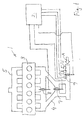
- Fig. 1 shows schematically parts of an internal combustion engine 1.
- the engine comprises a cylinder block 3, in this example provided with six cylinders arranged in a line, a variable air intake manifold 4, an exhaust manifold 5 and engine control means 2.
- the engine control means 2 here also referred to as an engine control unit, ECU, is provided for controlling various functions of the engine 1.
- the ECU 2 can be provided as one physical unit, or several interconnected elements. In operation air is introduced in the intake manifold 4, as depicted by the arrow A, by the control of a throttle valve 6, in turn controlled by the ECU.
- a pressure sensor 9 Downstream of the throttle valve 6 a pressure sensor 9 is provided and connected to the ECU 2 for providing values of the manifold absolute pressure (MAP).
- MAP manifold absolute pressure
- an airflow sensor 10 Upstream of the throttle valve 6 an airflow sensor 10, e.g. a thermal airflow meter as described in US6662640B2 , is provided and connected to the ECU 2 for providing values of the mass air flow (MAF).
- MAF mass air flow
- a temperature sensor 11 is provided and connected to the ECU 2 for providing values of the intake air temperature (IAT).
- the sensors 9, 10, 11 are known in the art and not described further here.
- the ECU can determine values of an air intake related parameter.
- variable air intake manifold 4 is provided with a first and a second manifold valve 7, 8, each manoeuvrable by a respective actuator (not depicted in fig. 1), in turn connected to and controllable by the ECU 2.
- the effective length of manifold conduits can be selected depending on the engine speed, so that an advantageous volumetric efficiency can be provided at different engine speed intervals. More specifically, the effective length of manifold conduits can be selected so as to obtain a resonance, advantageous for the volumetric efficiency, in the manifold at more than one engine speed value.
- the variable air intake manifold 4 provides for three intake modes.
- the curve I presents the volumetric efficiency of the engine at a first intake mode, in which both manifold valves 7, 8 are closed.
- the curve II presents the volumetric efficiency at a second intake mode, in which the first manifold valve 7 is open and the second manifold valve 8 is closed.
- the curve III presents the volumetric efficiency at a third intake mode, in which both manifold valves 7, 8 are open.
- the valves 7, 8 are operated to provide the greatest possible volumetric efficiency at each engine speed. Thereby, at engine speeds below a first threshold speed Ne1 the intake manifold 4 is set to the first intake mode (curve I), at engine speeds between the first threshold speed Ne1 and a second threshold speed Ne2 the intake manifold 4 is set to the second intake mode (curve II), and at engine speeds above the second threshold speed Ne2 the intake manifold 4 is set to the third intake mode (curve III).
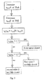
- the following steps are taken to establish a functional status of the variable air intake system in the first intake mode. More specifically the steps are take to establish whether both manifold valves 7, 8 are fully closed, and if any of them is not fully closed, to identify that valve.
- a first value n vol A of the volumetric efficiency at a first engine speed NeA, and a second value n vol B of the volumetric efficiency at a second engine speed NeB are determined.
- the second engine speed NeB is higher than the first engine speed NeA and within the engine speed interval of the first intake mode, i.e. below the first threshold speed Ne1.
- the efficiency ratio r nBA is compared to a first predetermined threshold value r1. If the efficiency ratio r nBA is larger than the first threshold value r1, it is determined that both manifold valves 7, 8 are fully closed, i.e. the variable intake system is in the correct mode.
- Determining the relative value r nBA of the volumetric efficiency as a ratio between the first and second values n vol A, n vol B of the volumetric efficiency is advantageous, since it makes any influence of sensor deviations very small.
- the first threshold value r1 is determined based on a first reference value rBI related to a correct function of the variable air intake system, (in this example: both valves 7, 8 are closed), and on a second reference value rBII related to a non-correct function of the variable air intake system, (in this example: the first valve 7 is not fully closed).
- the first threshold value r1 is predetermined as the mean value of the first reference value rBI and the second reference value rBII.
- the first threshold value r1 can be chosen to be closer to any of the first or second values rBII, rBII. Nevertheless, chosing the first threshold value r1 too close to the first reference value rBI may cause a false error detection of a functional system. Also, a threshold value r1 being too close to the second reference value rBII may cause a risk that a system error passes undetected.
- the efficiency ratio r nBA is smaller than the first threshold value r1, the efficiency ratio r nBA is compared to a second predetermined threshold value r2.
- the second threshold value r2 is determined in a manner corresponding to the first threshold value r1. This means that the second threshold value r2 is chosen based on predetermined information on the difference in the volumetric efficiency in a case were the first manifold valve 7 is not fully closed compared to a case where the second manifold valve 8 is not fully closed. In the latter case, the volumetric efficiency follows curve III in fig. 2. In the case where the first manifold valve 7 is not fully closed, but the second manifold valve 8 is fully closed, the volumetric efficiency follows curve II in fig. 2.
- the second threshold value r2 is chosen based on a volumetric efficiency value that lies between the volumetric efficiency values of curves II and III, at second engine speed NeB.
- the efficiency ratio r nBA is smaller than the second threshold value r2, it is determined that the second manifold valve 8 is not fully closed. If the efficiency ratio r nBA is larger than the second threshold value r2, (but smaller than the first threshold value r1), it is determined that the first manifold valve 7 is not fully closed.
- the second engine speed NeB is preferably chosen so as to give the largest possible difference regarding the efficiency ratio in a case of correct function of the air intake system compared to a case of malfunction thereof.
- a first value n vol B of the volumetric efficiency at a first engine speed NeB, and a second value n vol C of the volumetric efficiency at a second engine speed NeC are determined.
- the first engine speed NeB is within the engine speed interval of the first intake mode, i.e. below the first threshold speed Ne1.
- the second engine speed NeC is higher than the first engine speed NeB and within the engine speed interval of the second intake mode, i.e. above the first threshold speed Ne1 and below the second threshold speed Ne2.
- the efficiency ratio r nBC is compared to a third predetermined threshold efficiency ratio r3. If the efficiency ratio r nBC is larger than the third threshold value r3, it is determined that the first manifold valve 7 is not fully open. If the efficiency ratio r nBC is smaller than the third threshold value r3, it is determined that the first manifold valve 7 is fully open, as it should be.
- the third threshold value r3 is predetermined in a manner corresponding to the establishment of the first threshold value r1, described above.
- a first value n vol C of the volumetric efficiency at a first engine speed NeC, and a second value n vol D of the volumetric efficiency at a second engine speed NeD are determined.
- the first engine speed NeC is within the engine speed interval of the second intake mode, i.e. above the first threshold speed Ne1 and below the second threshold speed Ne2.
- the second engine speed NeD is higher than the first engine speed NeC and within the engine speed interval of the third intake mode, i.e. above the second threshold speed Ne2.
- the efficiency ratio r nCD is compared to a fourth predetermined threshold efficiency ratio r4. If the efficiency ratio r nCD is larger than the fourth threshold value r4, it is determined that the second manifold valve 8 is not fully open. If the efficiency ratio r nCD is smaller than the fourth threshold value r4, it is determined that the second manifold valve 8 is fully open, as it should be.
- the fourth threshold value r4 is predetermined in a manner corresponding to the establishment of the first threshold value r1, described above.
- an embodiment of the inventive method has been described in conjunction to a three mode air intake system.
- the invention is equally applicable to an air intake system with two intake modes, or a system with more than three intake modes.
- an embodiment of the inventive method in conjunction to an air intake system with two intake modes is described in conjunction with fig. 6-9.
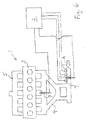
- Fig. 6 shows schematically parts of an internal combustion engine 1 with engine control means, ECU 2, therefore,
- the engine has the same features as the one shown in fig. 1, but differs regarding the following:
- variable air intake manifold 4 is provided with a manifold valve 7, manoeuvrable by an actuator (not depicted in fig. 6), in turn connected to and controllable by the ECU 2.
- a manifold valve 7 manoeuvrable by an actuator (not depicted in fig. 6), in turn connected to and controllable by the ECU 2.
- the effective length of manifold conduits can be selected depending on the engine speed, so that an advantageous volumetric efficiency can be provided at different engine speed intervals.
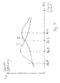
- the variable air intake manifold 4 provides for two intake modes. Referring to fig. 7, the curve I presents the volumetric efficiency of the engine at a first intake mode, in which the manifold valve 7 is closed. The curve II presents the volumetric efficiency at a second intake mode, in which the manifold valve 7 is open. To provide for the greatest possible volumetric efficiency at each engine speed, at engine speeds below a threshold speed Ne1 the intake manifold 4 is set to the first intake mode (curve I), and at engine speeds above the threshold speed Ne1 the intake manifold 4 is set to the second intake mode (curve II).
- n vol A, n vol B of the volumetric efficiency at a first and second engine speed NeA, NeB, respectively, are determined.
- An efficiency ratio r nBA n vol B/ n vol A is determined and compared to a first predetermined threshold efficiency ratio r1.
- the first threshold value r1 is predetermined in a manner corresponding to what has been described above. If the efficiency ratio r nBA is larger than the first threshold value r1, it is determined that the manifold valve 7 is fully closed, as it should be. If the efficiency ratio r nBA is smaller than the first threshold value r1, it is determined that the manifold valve 7 is not fully closed.
- n vol B, n vol C of the volumetric efficiency at a first and second engine speed NeB, NeC, respectively, are determined.
- the first engine speed NeB is within the engine speed interval of the first intake mode
- the second engine speed NeC is within the engine speed interval of the second intake mode.
- An efficiency ratio r nBC n vol B/ n vol C is determined and compared to a second predetermined threshold efficiency ratio r2.
- the second threshold value r2 is predetermined in a manner corresponding to what has been described above. If the efficiency ratio r nBC is larger than the second threshold value r2, it is determined that the manifold valve 7 is not open.
- r nAB n vol A/ n vol B
- r nBC n vol B/ n vol C
- alternatives are possible for the comparison of the first and second values of the volumetric efficiency.
Landscapes
- Engineering & Computer Science (AREA)
- Chemical & Material Sciences (AREA)
- Combustion & Propulsion (AREA)
- Mechanical Engineering (AREA)
- General Engineering & Computer Science (AREA)
- Health & Medical Sciences (AREA)
- Biomedical Technology (AREA)
- Combined Controls Of Internal Combustion Engines (AREA)
- Characterised By The Charging Evacuation (AREA)
Abstract
Description
- The present invention refers to a method for diagnosing a variable air intake system of an internal combustion engine, and an internal combustion engine comprising a variable air intake system.
- In known art, a number of methods for diagnosing valve functions in a non-variable engine air intake manifold have been suggested, see for example
US5138874A . - A variable air intake system for a combustion engine, for example as described in
US5638785A , usually comprises valves for guiding the intake air through conduits in dependence of the engine speed. For the function of such systems, it is critical that the valves are fully operational according to the design intentions of the system, i.e. that they open and close to guide the airflow as desired. Sensor deviations can cause erroneous diagnose and affect the operation of the engine negatively. - The object of the invention is to provide a large degree of certainty regarding diagnose information obtained regarding a variable air intake system of an internal combustion engine.
- This object is reached with a method for diagnosing a variable air intake system of an internal combustion engine, comprising the steps of
- determining a first value of an air intake related parameter at a first engine speed,
- determining a second value of the air intake related parameter at a second engine speed,
- comparing the first and second values of the air intake related parameter, and
- establishing, based on the comparison of the first and second values of the air intake related parameter, a functional status of the variable air intake system.
- Since the method according to the invention monitors the function of the variable air intake system by comparing two air intake related parameter values at respective engine speeds, the result is a low dependency of sensor tolerance deviations and ambient conditions influencing the sensors. Specifically, the method according to the invention is less vulnerable to such sensor deviations, compared to a method involving analysis of absolute sensor values or absolute values of an air intake related parameter based on sensor values. Thereby, the inventive method increases the degree of certainty regarding the diagnose information.
- For this presentation, the air intake related parameter shall be understood as a parameter that can be used to derive a status of the engine air intake system. Preferably, the air intake related parameter is the volumetric efficiency of the engine. This is of considerable advantage, since the volumetric efficiency is closely related to the operation of the air intake manifold, and since it provides relevant information irrespective of engine operational settings and conditions, such as the throttle setting, fuel supply, and ignition setting.
- As explained in detail below, the volumetric efficiency is determined based on values of the intake air temperature, the intake air mass flow, the engine speed, and the manifold absolute pressure. Alternatively, if the volumetric efficiency is based on values obtained exclusively at open throttle conditions, instead of the manifold absolute pressure, the atmospheric pressure can be used for determining the volumetric efficiency.
- As an alternative to using volumetric efficiency as the air intake related parameter, the latter can be based on engine torque or engine output power, determined in manners known in the art. Thereby, the air intake related parameter should also be based on fuel flow and ignition as a function of the crankshaft angle.
- Advantageous embodiments are defined in claims 3-6, and are more closely described below.
- The object stated above is also reached with an internal combustion engine according to any of the claims 7-12.
- Below, the invention will be described in greater detail with reference to the drawing, in which
- fig. 1 shows schematically parts of an internal combustion engine and a control system therefore,
- fig. 2 is a diagram of the volumetric efficiency as a function of engine speed concerning the engine in fig. 1,
- fig. 3, fig. 4 and fig. 5 are block diagrams depicting steps in methods in connection to the engine in fig. 1,
- fig. 6 shows schematically parts of an alternative internal combustion engine and a control system therefore,
- fig. 7 is a diagram of the volumetric efficiency as a function of engine speed concerning the engine in fig. 6, and
- fig. 8 and fig. 9 are block diagrams depicting steps in methods in connection to the engine in fig. 6.
- Fig. 1 shows schematically parts of an
internal combustion engine 1. The engine comprises acylinder block 3, in this example provided with six cylinders arranged in a line, a variableair intake manifold 4, anexhaust manifold 5 and engine control means 2. The engine control means 2, here also referred to as an engine control unit, ECU, is provided for controlling various functions of theengine 1. The ECU 2 can be provided as one physical unit, or several interconnected elements. In operation air is introduced in theintake manifold 4, as depicted by the arrow A, by the control of athrottle valve 6, in turn controlled by the ECU. - Downstream of the throttle valve 6 a
pressure sensor 9 is provided and connected to theECU 2 for providing values of the manifold absolute pressure (MAP). Upstream of thethrottle valve 6 an airflow sensor 10, e.g. a thermal airflow meter as described inUS6662640B2 , is provided and connected to theECU 2 for providing values of the mass air flow (MAF). Also, upstream of the throttle valve 6 a temperature sensor 11 is provided and connected to theECU 2 for providing values of the intake air temperature (IAT). Thesensors 9, 10, 11 are known in the art and not described further here. - The ECU can determine values of an air intake related parameter. In this embodiment, the air intake related parameter is the volumetric efficiency nvol of the engine, determined based partly on information obtained from the
sensors 9, 10, 11, and according to the equation:
where: IAT = intake air temperature, MAF = intake air mass flow, Ne = engine speed, and MAP = manifold absolute pressure. - The variable
air intake manifold 4 is provided with a first and asecond manifold valve ECU 2. As is known in the art, by suitable control of the manifold valve settings, the effective length of manifold conduits can be selected depending on the engine speed, so that an advantageous volumetric efficiency can be provided at different engine speed intervals. More specifically, the effective length of manifold conduits can be selected so as to obtain a resonance, advantageous for the volumetric efficiency, in the manifold at more than one engine speed value. - The variable
air intake manifold 4 provides for three intake modes. Referring to fig. 2, the curve I presents the volumetric efficiency of the engine at a first intake mode, in which bothmanifold valves first manifold valve 7 is open and thesecond manifold valve 8 is closed. The curve III presents the volumetric efficiency at a third intake mode, in which bothmanifold valves - The
valves intake manifold 4 is set to the first intake mode (curve I), at engine speeds between the first threshold speed Ne1 and a second threshold speed Ne2 theintake manifold 4 is set to the second intake mode (curve II), and at engine speeds above the second threshold speed Ne2 theintake manifold 4 is set to the third intake mode (curve III). - Referring to fig. 2 and fig. 3, the following steps are taken to establish a functional status of the variable air intake system in the first intake mode. More specifically the steps are take to establish whether both
manifold valves - By comparing the first and second values nvol A, nvol B of the volumetric efficiency, a relative value rnBA of the volumetric efficiency is determined as the efficiency ratio rnBA = nvol B/nvol A. The efficiency ratio rnBA is compared to a first predetermined threshold value r1. If the efficiency ratio rnBA is larger than the first threshold value r1, it is determined that both
manifold valves - Determining the relative value rnBA of the volumetric efficiency as a ratio between the first and second values nvol A, nvol B of the volumetric efficiency is advantageous, since it makes any influence of sensor deviations very small.
- The first threshold value r1 is determined based on a first reference value rBI related to a correct function of the variable air intake system, (in this example: both
valves first valve 7 is not fully closed). Referring to fig. 2, the first reference value rBI is determined as rBI = nvol BI/nvo A, where nvol BI is a value of the volumetric efficiency at the second engine speed NeB and at a correct function of the variable air intake system. The second reference value rBII is determined as rBII = nvol BII/nvol A, where nvol BII is a value of the volumetric efficiency at the same engine speed NeB and at a non-correct function of the variable air intake system. Preferably, the first threshold value r1 is predetermined as the mean value of the first reference value rBI and the second reference value rBII. However, alternatively the first threshold value r1 can be chosen to be closer to any of the first or second values rBII, rBII. Nevertheless, chosing the first threshold value r1 too close to the first reference value rBI may cause a false error detection of a functional system. Also, a threshold value r1 being too close to the second reference value rBII may cause a risk that a system error passes undetected. - Referring again to fig. 3, if the efficiency ratio rnBA is smaller than the first threshold value r1, the efficiency ratio rnBA is compared to a second predetermined threshold value r2. The second threshold value r2 is determined in a manner corresponding to the first threshold value r1. This means that the second threshold value r2 is chosen based on predetermined information on the difference in the volumetric efficiency in a case were the
first manifold valve 7 is not fully closed compared to a case where thesecond manifold valve 8 is not fully closed. In the latter case, the volumetric efficiency follows curve III in fig. 2. In the case where thefirst manifold valve 7 is not fully closed, but thesecond manifold valve 8 is fully closed, the volumetric efficiency follows curve II in fig. 2. The second threshold value r2 is chosen based on a volumetric efficiency value that lies between the volumetric efficiency values of curves II and III, at second engine speed NeB. - Thus, in this embodiment, if the efficiency ratio rnBA is smaller than the second threshold value r2, it is determined that the
second manifold valve 8 is not fully closed. If the efficiency ratio rnBA is larger than the second threshold value r2, (but smaller than the first threshold value r1), it is determined that thefirst manifold valve 7 is not fully closed. - It should be noted that the second engine speed NeB is preferably chosen so as to give the largest possible difference regarding the efficiency ratio in a case of correct function of the air intake system compared to a case of malfunction thereof.
- Referring to fig. 2 and fig. 4, the following steps are taken to check whether the
first manifold valve 7 is fully open in the second intake mode. A first value nvol B of the volumetric efficiency at a first engine speed NeB, and a second value nvol C of the volumetric efficiency at a second engine speed NeC are determined. The first engine speed NeB is within the engine speed interval of the first intake mode, i.e. below the first threshold speed Ne1. The second engine speed NeC is higher than the first engine speed NeB and within the engine speed interval of the second intake mode, i.e. above the first threshold speed Ne1 and below the second threshold speed Ne2. - By comparing the first and second values nvol B, nvol C of the volumetric efficiency, a relative value rnBC of the volumetric efficiency is determined as the efficiency ratio rnBC = nvol B/nvol C. The efficiency ratio rnBC is compared to a third predetermined threshold efficiency ratio r3. If the efficiency ratio rnBC is larger than the third threshold value r3, it is determined that the
first manifold valve 7 is not fully open. If the efficiency ratio rnBC is smaller than the third threshold value r3, it is determined that thefirst manifold valve 7 is fully open, as it should be. - The third threshold value r3 is predetermined in a manner corresponding to the establishment of the first threshold value r1, described above.
- Referring to fig. 2 and fig. 5, the following steps are taken to check whether the
second manifold valve 8 is fully open in the third intake mode. A first value nvol C of the volumetric efficiency at a first engine speed NeC, and a second value nvol D of the volumetric efficiency at a second engine speed NeD are determined. The first engine speed NeC is within the engine speed interval of the second intake mode, i.e. above the first threshold speed Ne1 and below the second threshold speed Ne2. The second engine speed NeD is higher than the first engine speed NeC and within the engine speed interval of the third intake mode, i.e. above the second threshold speed Ne2. - By comparing the first and second values nvol C, nvol D of the volumetric efficiency, a relative value rnCD of the volumetric efficiency is determined as the efficiency ratio rnCD = nvol C/nvol D. The efficiency ratio rnCD is compared to a fourth predetermined threshold efficiency ratio r4. If the efficiency ratio rnCD is larger than the fourth threshold value r4, it is determined that the
second manifold valve 8 is not fully open. If the efficiency ratio rnCD is smaller than the fourth threshold value r4, it is determined that thesecond manifold valve 8 is fully open, as it should be. - The fourth threshold value r4 is predetermined in a manner corresponding to the establishment of the first threshold value r1, described above.
- Above, an embodiment of the inventive method has been described in conjunction to a three mode air intake system. However, the invention is equally applicable to an air intake system with two intake modes, or a system with more than three intake modes. Below, an embodiment of the inventive method in conjunction to an air intake system with two intake modes is described in conjunction with fig. 6-9.
- Fig. 6 shows schematically parts of an
internal combustion engine 1 with engine control means,ECU 2, therefore, The engine has the same features as the one shown in fig. 1, but differs regarding the following: - The variable
air intake manifold 4 is provided with amanifold valve 7, manoeuvrable by an actuator (not depicted in fig. 6), in turn connected to and controllable by theECU 2. As is known in the art, by suitable control of themanifold valve 7 setting, the effective length of manifold conduits can be selected depending on the engine speed, so that an advantageous volumetric efficiency can be provided at different engine speed intervals. - The variable
air intake manifold 4 provides for two intake modes. Referring to fig. 7, the curve I presents the volumetric efficiency of the engine at a first intake mode, in which themanifold valve 7 is closed. The curve II presents the volumetric efficiency at a second intake mode, in which themanifold valve 7 is open. To provide for the greatest possible volumetric efficiency at each engine speed, at engine speeds below a threshold speed Ne1 theintake manifold 4 is set to the first intake mode (curve I), and at engine speeds above the threshold speed Ne1 theintake manifold 4 is set to the second intake mode (curve II). - Referring to fig. 7 and fig. 8, steps taken to check whether the
manifold valve 7 is fully closed in the first intake mode, correspond to the steps described above, with reference to fig. 2, to check whether bothmanifold valves - An efficiency ratio rnBA = nvol B/nvol A is determined and compared to a first predetermined threshold efficiency ratio r1. The first threshold value r1 is predetermined in a manner corresponding to what has been described above. If the efficiency ratio rnBA is larger than the first threshold value r1, it is determined that the
manifold valve 7 is fully closed, as it should be. If the efficiency ratio rnBA is smaller than the first threshold value r1, it is determined that themanifold valve 7 is not fully closed. - Referring to fig. 7 and fig. 9, the following steps are taken to check whether the
manifold valve 7 is open in the second intake mode. A first and a second value nvol B, nvol C of the volumetric efficiency at a first and second engine speed NeB, NeC, respectively, are determined. The first engine speed NeB is within the engine speed interval of the first intake mode, and the second engine speed NeC is within the engine speed interval of the second intake mode. - An efficiency ratio rnBC = nvol B/nvol C is determined and compared to a second predetermined threshold efficiency ratio r2. The second threshold value r2 is predetermined in a manner corresponding to what has been described above. If the efficiency ratio rnBC is larger than the second threshold value r2, it is determined that the
manifold valve 7 is not open. - Above, comparing the first and second values of the volumetric efficiency has been described as comprising determining a relative value rnAB, rnBC, rnCD of the volumetric efficiency as the efficiency ratio rnAB=nvol A/nvol B, rnBC=nvol B/nvol C and rnCD=nvol C/nvol D, respectively. However, alternatives are possible for the comparison of the first and second values of the volumetric efficiency. For example, said comparison could comprise determining a relative value of the volumetric efficiency as the efficiency difference rnAB=nvol A - nvol B, rnBC=nvol B - nvol C and rnCD =nvol C - nvol D, respectively.
Claims (12)
- A method for diagnosing a variable air intake system (4, 7, 8) of an internal combustion engine (1), characterized by the steps of- determining a first value (nvol A, nvol B, nvol C) of an air intake related parameter at a first engine speed (NeA, NeB, NeC),- determining a second value (nvol B, nvol C, nvol D) of the air intake related parameter at a second engine speed (NeB, NeC, NeD),- comparing the first and second values (nvol A, nvol B, nvol C, nvol D) of the air intake related parameter, and- establishing, based on the comparison of the first and second values (nvol A, hvol B, hvol C, nvol D) of the air intake related parameter, a functional status of the variable air intake system.
- A method according to claim 1, wherein the air intake related parameter is the volumetric efficiency of the engine.
- A method according to any of the preceding claims, wherein the functional status of the variable air intake system refers to the functional status of at least one valve (7, 8) in the variable intake system.
- A method according to any of the preceding claims, wherein the step of comparing the first and second values (nvol A, nvol B, nvol C, nvol D) of the air intake related parameter comprises determining a relative value (rnAB, rnBC, rncD ) of the air intake related parameter, based on the first and second values (nvol A, nvol B, hvol C, nvol D) of the air intake related parameter, the method further comprising the step of comparing the relative value (rnAB, rnBC, rncD ) of the air intake related parameter to a predetermined threshold value (r1, r2, r3, r4).
- A method according to claim 4, wherein the step of determining a relative value (rnAB, rnBC, rnCD ) of the air intake related parameter, comprises determining the relative value (rnAB, rnBC, rnCD ) of the air intake related parameter as a ratio between the first and second values (nvol A, nvol B, nvol C, nvol D) of the air intake related parameter.
- A method according to claim 4 or 5, wherein the threshold value (r1, r2, r3, r4) is dependent on a value (nvol BI) of the air intake related parameter at a correct function of the variable air intake system, and on a value (nvol BII) of the air intake related parameter at a non-correct function of the variable air intake system.
- An internal combustion engine comprising a variable air intake system (4, 7, 8) and engine control means (2), characterized in that the engine control means (2) is adapted to determine a first value (nvol A, nvol B, nvol C) of an air intake related parameter at a first engine speed (NeA, NeB, NeC), and a second value (nvol B, nvol C, nvol D) of the air intake related parameter at a second engine speed (NeB, NeC, NeD), and in that the engine control means (2) is further adapted to compare the first and second values of the air intake related parameter, and to establish, based on the comparison of the first and second values (nvol A, nvol B, nvol C, nvol D) of the air intake related parameter, a functional status of the variable air intake system.
- An internal combustion engine according to claim 7, wherein the air intake related parameter is the volumetric efficiency of the engine.
- An internal combustion engine according to claim 7 or 8, wherein the functional status of the variable air intake system refers to the functional status of at least one valve (7, 8) in the variable intake system.
- An internal combustion engine according to claim 7, 8 or 9, wherein the engine control means (2) is adapted to determine a relative value (rnAB, rnBC, nncD ) of the air intake related parameter, based on the first and second values (nvol A, nvol B, nvol C, nvol D) of the air intake related parameter, the engine control means (2) further being adapted to compare the relative value (rnAB, rnBC, rnCD ) of the air intake related parameter to a predetermined threshold value (r1, r2, r3, r4).
- An internal combustion engine according to claim 10, wherein the engine control means (2) is adapted to determine the relative value (rnAB, rnBC , rnCD ) of the air intake related parameter as a ratio between the first and second values (nvol A, nvol B, nvol C, nvol D) of the air intake related parameter.
- An internal combustion engine according to claim 10 or 11, wherein the threshold value (r1, r2, r3, r4) is dependent on a value (nvol BI) of the air intake related parameter at a correct function of the variable air intake system, and the second reference value (rBII) is dependent on a value (nvol BII) of the air intake related parameter at a non-correct function of the variable air intake system.
Priority Applications (4)
| Application Number | Priority Date | Filing Date | Title |
|---|---|---|---|
| DE602005008975T DE602005008975D1 (en) | 2005-10-03 | 2005-10-03 | Method for a variable intake system and internal combustion engine with a variable intake system |
| EP05109144A EP1770258B1 (en) | 2005-10-03 | 2005-10-03 | A method for a variable air intake system and an internal combustion engine comprising a variable air intake system. |
| EP06113932A EP1770259B1 (en) | 2005-10-03 | 2006-05-15 | A method for a variable air intake system, and an internal combustion engine comprising a variable air intake system. |
| DE602006003499T DE602006003499D1 (en) | 2005-10-03 | 2006-05-15 | Method for a variable intake system and internal combustion engine with a variable intake system |
Applications Claiming Priority (1)
| Application Number | Priority Date | Filing Date | Title |
|---|---|---|---|
| EP05109144A EP1770258B1 (en) | 2005-10-03 | 2005-10-03 | A method for a variable air intake system and an internal combustion engine comprising a variable air intake system. |
Publications (2)
| Publication Number | Publication Date |
|---|---|
| EP1770258A1 true EP1770258A1 (en) | 2007-04-04 |
| EP1770258B1 EP1770258B1 (en) | 2008-08-13 |
Family
ID=35355628
Family Applications (2)
| Application Number | Title | Priority Date | Filing Date |
|---|---|---|---|
| EP05109144A Expired - Lifetime EP1770258B1 (en) | 2005-10-03 | 2005-10-03 | A method for a variable air intake system and an internal combustion engine comprising a variable air intake system. |
| EP06113932A Ceased EP1770259B1 (en) | 2005-10-03 | 2006-05-15 | A method for a variable air intake system, and an internal combustion engine comprising a variable air intake system. |
Family Applications After (1)
| Application Number | Title | Priority Date | Filing Date |
|---|---|---|---|
| EP06113932A Ceased EP1770259B1 (en) | 2005-10-03 | 2006-05-15 | A method for a variable air intake system, and an internal combustion engine comprising a variable air intake system. |
Country Status (2)
| Country | Link |
|---|---|
| EP (2) | EP1770258B1 (en) |
| DE (2) | DE602005008975D1 (en) |
Cited By (2)
| Publication number | Priority date | Publication date | Assignee | Title |
|---|---|---|---|---|
| CN105673238A (en) * | 2016-01-13 | 2016-06-15 | 奇瑞汽车股份有限公司 | Diagnostic method of engine variable intake manifold execution mechanism |
| US11359563B2 (en) * | 2017-06-02 | 2022-06-14 | Vitesco Technologies GmbH | Method for determining the current trimming of the intake tract of an internal combustion engine during operation |
Citations (6)
| Publication number | Priority date | Publication date | Assignee | Title |
|---|---|---|---|---|
| JPS61247822A (en) * | 1985-04-25 | 1986-11-05 | Mazda Motor Corp | Intake apparatus of engine |
| US5138874A (en) | 1991-07-01 | 1992-08-18 | General Motors Corporation | Diagnostic system for detecting faults in engine air intake check valves |
| US5638785A (en) | 1996-10-15 | 1997-06-17 | Ford Motor Company | Variable air intake manifold |
| DE19727669A1 (en) * | 1997-06-30 | 1999-01-07 | Bosch Gmbh Robert | Monitoring function throttle flap of IC engine |
| US6662640B2 (en) | 2000-10-19 | 2003-12-16 | Denso Corporation | Air amount detector for internal combustion engine |
| DE10346734B3 (en) * | 2003-10-08 | 2005-04-21 | Bayerische Motoren Werke Ag | Method for fault diagnosis with a variable intake manifold in the intake system of an internal combustion engine |
Family Cites Families (2)
| Publication number | Priority date | Publication date | Assignee | Title |
|---|---|---|---|---|
| US6546789B1 (en) * | 1997-06-30 | 2003-04-15 | Robert Bosch Gmbh | Method and arrangement for monitoring the operation of an intake-manifold flap for switching over the intake manifold of an internal combustion engine |
| EP1655466B1 (en) * | 2004-11-05 | 2007-03-21 | Ford Global Technologies, LLC | Method for diagnosing variable intake system failure |
-
2005
- 2005-10-03 DE DE602005008975T patent/DE602005008975D1/en not_active Expired - Lifetime
- 2005-10-03 EP EP05109144A patent/EP1770258B1/en not_active Expired - Lifetime
-
2006
- 2006-05-15 DE DE602006003499T patent/DE602006003499D1/en not_active Expired - Lifetime
- 2006-05-15 EP EP06113932A patent/EP1770259B1/en not_active Ceased
Patent Citations (6)
| Publication number | Priority date | Publication date | Assignee | Title |
|---|---|---|---|---|
| JPS61247822A (en) * | 1985-04-25 | 1986-11-05 | Mazda Motor Corp | Intake apparatus of engine |
| US5138874A (en) | 1991-07-01 | 1992-08-18 | General Motors Corporation | Diagnostic system for detecting faults in engine air intake check valves |
| US5638785A (en) | 1996-10-15 | 1997-06-17 | Ford Motor Company | Variable air intake manifold |
| DE19727669A1 (en) * | 1997-06-30 | 1999-01-07 | Bosch Gmbh Robert | Monitoring function throttle flap of IC engine |
| US6662640B2 (en) | 2000-10-19 | 2003-12-16 | Denso Corporation | Air amount detector for internal combustion engine |
| DE10346734B3 (en) * | 2003-10-08 | 2005-04-21 | Bayerische Motoren Werke Ag | Method for fault diagnosis with a variable intake manifold in the intake system of an internal combustion engine |
Non-Patent Citations (1)
| Title |
|---|
| PATENT ABSTRACTS OF JAPAN vol. 011, no. 098 (M - 575) 27 March 1987 (1987-03-27) * |
Cited By (2)
| Publication number | Priority date | Publication date | Assignee | Title |
|---|---|---|---|---|
| CN105673238A (en) * | 2016-01-13 | 2016-06-15 | 奇瑞汽车股份有限公司 | Diagnostic method of engine variable intake manifold execution mechanism |
| US11359563B2 (en) * | 2017-06-02 | 2022-06-14 | Vitesco Technologies GmbH | Method for determining the current trimming of the intake tract of an internal combustion engine during operation |
Also Published As
| Publication number | Publication date |
|---|---|
| EP1770258B1 (en) | 2008-08-13 |
| EP1770259A1 (en) | 2007-04-04 |
| EP1770259B1 (en) | 2008-11-05 |
| DE602005008975D1 (en) | 2008-09-25 |
| DE602006003499D1 (en) | 2008-12-18 |
Similar Documents
| Publication | Publication Date | Title |
|---|---|---|
| US6687601B2 (en) | System for diagnosing an air handling mechanism of an internal combustion engine | |
| EP1705357B1 (en) | Method and a relative device for diagnosing misfire or partial combustion conditions in an internal combustion engine | |
| US7677091B2 (en) | Air-fuel ratio controller for an internal combustion engine and diagnosis apparatus for intake sensors | |
| US7104259B2 (en) | Diagnostic device for exhaust gas recirculation system | |
| EP2840244B1 (en) | Control device for internal combustion engine equipped with supercharger | |
| JP7193017B2 (en) | LEAK DIAGNOSIS METHOD AND LEAK DIAGNOSIS DEVICE FOR BLOW-BY GAS PROCESSING DEVICE FOR INTERNAL COMBUSTION ENGINE | |
| EP2010777B1 (en) | Control apparatus and control method for internal combustion engine having centrifugal compressor | |
| EP1746275B1 (en) | Monitoring system for internal combustion engine | |
| EP3029307A1 (en) | Control device for internal combustion engine | |
| US7631551B2 (en) | Adaptive barometric pressure estimation in which an internal combustion engine is located | |
| JP7193016B2 (en) | LEAK DIAGNOSIS METHOD AND LEAK DIAGNOSIS DEVICE FOR BLOW-BY GAS PROCESSING DEVICE FOR INTERNAL COMBUSTION ENGINE | |
| CN101054928A (en) | Charge motion control valve fuzzy logic diagnostic | |
| EP2052144B1 (en) | Apparatus for and method of controlling internal combustion engine equipped with turbocharger | |
| WO2022074957A1 (en) | Electronic control device and engine control system | |
| EP1770258B1 (en) | A method for a variable air intake system and an internal combustion engine comprising a variable air intake system. | |
| US9239577B2 (en) | Method and device for carrying out an onboard diagnosis | |
| US11614043B2 (en) | Method for setting a throttle valve, engine control unit, and a vehicle | |
| US9347418B2 (en) | Method of monitoring EGR system | |
| CN119373588B (en) | A hydrogen engine exhaust measurement device, performance diagnosis method and system | |
| JP2007205339A (en) | Turbocharger state quantity estimation device | |
| EP3112652B1 (en) | Egr control method and egr device | |
| JP4259570B2 (en) | Valve abnormality determination device, abnormality determination method, program for realizing the method, and recording medium recording the program | |
| EP4116548B1 (en) | Abnormality diagnostic method for internal combustion engine and abnormality diagnostic device for internal combustion engine | |
| JPH1047130A (en) | Internal combustion engine abnormality detection device | |
| JP6494822B1 (en) | Control device for internal combustion engine and control method for internal combustion engine |
Legal Events
| Date | Code | Title | Description |
|---|---|---|---|
| PUAI | Public reference made under article 153(3) epc to a published international application that has entered the european phase |
Free format text: ORIGINAL CODE: 0009012 |
|
| AK | Designated contracting states |
Kind code of ref document: A1 Designated state(s): AT BE BG CH CY CZ DE DK EE ES FI FR GB GR HU IE IS IT LI LT LU LV MC NL PL PT RO SE SI SK TR |
|
| AX | Request for extension of the european patent |
Extension state: AL BA HR MK YU |
|
| 17P | Request for examination filed |
Effective date: 20071001 |
|
| 17Q | First examination report despatched |
Effective date: 20071102 |
|
| AKX | Designation fees paid |
Designated state(s): DE GB SE |
|
| GRAP | Despatch of communication of intention to grant a patent |
Free format text: ORIGINAL CODE: EPIDOSNIGR1 |
|
| GRAS | Grant fee paid |
Free format text: ORIGINAL CODE: EPIDOSNIGR3 |
|
| GRAA | (expected) grant |
Free format text: ORIGINAL CODE: 0009210 |
|
| AK | Designated contracting states |
Kind code of ref document: B1 Designated state(s): DE GB SE |
|
| REG | Reference to a national code |
Ref country code: GB Ref legal event code: FG4D |
|
| REF | Corresponds to: |
Ref document number: 602005008975 Country of ref document: DE Date of ref document: 20080925 Kind code of ref document: P |
|
| REG | Reference to a national code |
Ref country code: SE Ref legal event code: TRGR |
|
| PLBE | No opposition filed within time limit |
Free format text: ORIGINAL CODE: 0009261 |
|
| STAA | Information on the status of an ep patent application or granted ep patent |
Free format text: STATUS: NO OPPOSITION FILED WITHIN TIME LIMIT |
|
| 26N | No opposition filed |
Effective date: 20090514 |
|
| REG | Reference to a national code |
Ref country code: GB Ref legal event code: 732E Free format text: REGISTERED BETWEEN 20111020 AND 20111025 |
|
| REG | Reference to a national code |
Ref country code: DE Ref legal event code: R082 Ref document number: 602005008975 Country of ref document: DE Representative=s name: HOFFMANN - EITLE, DE |
|
| REG | Reference to a national code |
Ref country code: DE Ref legal event code: R082 Ref document number: 602005008975 Country of ref document: DE Representative=s name: HOFFMANN - EITLE, DE Effective date: 20120207 Ref country code: DE Ref legal event code: R081 Ref document number: 602005008975 Country of ref document: DE Owner name: VOLVO CAR CORPORATION, SE Free format text: FORMER OWNER: FORD GLOBAL TECHNOLOGIES, LLC, DEARBORN, MICH., US Effective date: 20120207 Ref country code: DE Ref legal event code: R082 Ref document number: 602005008975 Country of ref document: DE Representative=s name: HOFFMANN - EITLE PATENT- UND RECHTSANWAELTE PA, DE Effective date: 20120207 |
|
| PGFP | Annual fee paid to national office [announced via postgrant information from national office to epo] |
Ref country code: DE Payment date: 20141015 Year of fee payment: 10 Ref country code: SE Payment date: 20141027 Year of fee payment: 10 Ref country code: GB Payment date: 20141015 Year of fee payment: 10 |
|
| REG | Reference to a national code |
Ref country code: DE Ref legal event code: R119 Ref document number: 602005008975 Country of ref document: DE |
|
| REG | Reference to a national code |
Ref country code: SE Ref legal event code: EUG |
|
| GBPC | Gb: european patent ceased through non-payment of renewal fee |
Effective date: 20151003 |
|
| PG25 | Lapsed in a contracting state [announced via postgrant information from national office to epo] |
Ref country code: DE Free format text: LAPSE BECAUSE OF NON-PAYMENT OF DUE FEES Effective date: 20160503 Ref country code: GB Free format text: LAPSE BECAUSE OF NON-PAYMENT OF DUE FEES Effective date: 20151003 |
|
| PG25 | Lapsed in a contracting state [announced via postgrant information from national office to epo] |
Ref country code: SE Free format text: LAPSE BECAUSE OF NON-PAYMENT OF DUE FEES Effective date: 20151004 |