EP1770035A1 - Sheet supplying apparatus - Google Patents
Sheet supplying apparatus Download PDFInfo
- Publication number
- EP1770035A1 EP1770035A1 EP06019903A EP06019903A EP1770035A1 EP 1770035 A1 EP1770035 A1 EP 1770035A1 EP 06019903 A EP06019903 A EP 06019903A EP 06019903 A EP06019903 A EP 06019903A EP 1770035 A1 EP1770035 A1 EP 1770035A1
- Authority
- EP
- European Patent Office
- Prior art keywords
- sheet
- recording
- recording sheets
- supply
- supply path
- Prior art date
- Legal status (The legal status is an assumption and is not a legal conclusion. Google has not performed a legal analysis and makes no representation as to the accuracy of the status listed.)
- Granted
Links
- 238000011144 upstream manufacturing Methods 0.000 claims description 8
- 230000001154 acute effect Effects 0.000 claims description 4
- 239000000976 ink Substances 0.000 description 26
- 230000003247 decreasing effect Effects 0.000 description 6
- 238000012423 maintenance Methods 0.000 description 6
- 238000007599 discharging Methods 0.000 description 5
- 238000010276 construction Methods 0.000 description 4
- 238000005192 partition Methods 0.000 description 4
- 239000011521 glass Substances 0.000 description 3
- 238000004519 manufacturing process Methods 0.000 description 2
- 230000036544 posture Effects 0.000 description 2
- 229920003002 synthetic resin Polymers 0.000 description 2
- 239000000057 synthetic resin Substances 0.000 description 2
- 238000005452 bending Methods 0.000 description 1
- 230000005540 biological transmission Effects 0.000 description 1
- 238000001514 detection method Methods 0.000 description 1
- 230000005489 elastic deformation Effects 0.000 description 1
- 238000011010 flushing procedure Methods 0.000 description 1
- 238000001746 injection moulding Methods 0.000 description 1
- 230000002452 interceptive effect Effects 0.000 description 1
- 239000004973 liquid crystal related substance Substances 0.000 description 1
- 230000004048 modification Effects 0.000 description 1
- 238000012986 modification Methods 0.000 description 1
- 230000004044 response Effects 0.000 description 1
Images






Classifications
-
- B—PERFORMING OPERATIONS; TRANSPORTING
- B65—CONVEYING; PACKING; STORING; HANDLING THIN OR FILAMENTARY MATERIAL
- B65H—HANDLING THIN OR FILAMENTARY MATERIAL, e.g. SHEETS, WEBS, CABLES
- B65H3/00—Separating articles from piles
- B65H3/44—Simultaneously, alternately, or selectively separating articles from two or more piles
-
- B—PERFORMING OPERATIONS; TRANSPORTING
- B65—CONVEYING; PACKING; STORING; HANDLING THIN OR FILAMENTARY MATERIAL
- B65H—HANDLING THIN OR FILAMENTARY MATERIAL, e.g. SHEETS, WEBS, CABLES
- B65H3/00—Separating articles from piles
- B65H3/46—Supplementary devices or measures to assist separation or prevent double feed
- B65H3/56—Elements, e.g. scrapers, fingers, needles, brushes, acting on separated article or on edge of the pile
-
- B—PERFORMING OPERATIONS; TRANSPORTING
- B65—CONVEYING; PACKING; STORING; HANDLING THIN OR FILAMENTARY MATERIAL
- B65H—HANDLING THIN OR FILAMENTARY MATERIAL, e.g. SHEETS, WEBS, CABLES
- B65H2405/00—Parts for holding the handled material
- B65H2405/10—Cassettes, holders, bins, decks, trays, supports or magazines for sheets stacked substantially horizontally
- B65H2405/11—Parts and details thereof
- B65H2405/113—Front, i.e. portion adjacent to the feeding / delivering side
- B65H2405/1134—Front, i.e. portion adjacent to the feeding / delivering side movable, e.g. pivotable
-
- B—PERFORMING OPERATIONS; TRANSPORTING
- B65—CONVEYING; PACKING; STORING; HANDLING THIN OR FILAMENTARY MATERIAL
- B65H—HANDLING THIN OR FILAMENTARY MATERIAL, e.g. SHEETS, WEBS, CABLES
- B65H2405/00—Parts for holding the handled material
- B65H2405/10—Cassettes, holders, bins, decks, trays, supports or magazines for sheets stacked substantially horizontally
- B65H2405/11—Parts and details thereof
- B65H2405/113—Front, i.e. portion adjacent to the feeding / delivering side
- B65H2405/1136—Front, i.e. portion adjacent to the feeding / delivering side inclined, i.e. forming an angle different from 90 with the bottom
-
- B—PERFORMING OPERATIONS; TRANSPORTING
- B65—CONVEYING; PACKING; STORING; HANDLING THIN OR FILAMENTARY MATERIAL
- B65H—HANDLING THIN OR FILAMENTARY MATERIAL, e.g. SHEETS, WEBS, CABLES
- B65H2405/00—Parts for holding the handled material
- B65H2405/30—Other features of supports for sheets
- B65H2405/33—Compartmented support
- B65H2405/332—Superposed compartments
Definitions
- the present invention relates to a sheet supplying apparatus that supplies a plurality of recording sheets, one by one, while separating the recording sheets from each other.
- a conventional image recording device such as a printer or a facsimile machine, includes an image recording portion and a sheet-supply cassette that accommodates a plurality of stacked recording sheets each as a recording medium, and supplies the recording sheets, one by one, from the sheet-supply cassette to the image recording portion so that the image recording portion may record an image on each recording sheet.
- Patent Document 1 i.e., Japanese Patent Application Publication No. 2004-149297 or its corresponding U.S. Patent Application Publication No.
- 2004-084831 A1 discloses a sheet supplying device including a sheet accommodating portion that accommodates a plurality of stacked recording sheets in their inclined postures; a sheet-supply roller that is pressed on the uppermost one of the stacked recording sheets; and a sheet separating portion that is supported by a bottom plate such that respective lower (i.e., leading) ends of the stacked recording sheets are held in contact with the sheet separating portion.
- the sheet separating portion includes a plurality of projecting portions that are arranged at regular intervals of distance, along a sheet-supply path along which each recording sheet is supplied; a plurality of pairs of arm portions each pair of which supports a corresponding one of the projecting portions, on either side of the one projecting portion; and a continuous base portion that continuously connects the arm portions to each other and thereby supports the arm portions.
- the sheet separating portion is held by a holder that is formed of a metallic plate and is fixed to the bottom plate, such that the projecting portions project by respective predetermined amounts through an elongate hole of the holder that is elongate along the sheet-supply path.
- the leading end of the uppermost recording sheet pushes an appropriate one of the projecting portions, and consequently the one projecting portion is moved downward into the elongate hole of the holder because of elastic deformation of the corresponding arm portion. Since, however, the other recording sheets than the uppermost recording sheet are not moved because the respective leading ends thereof are engaged with the other projecting portions that remain projecting from the elongate hole, only the uppermost recording sheet is separated from the other recording sheets and is conveyed forward.
- Patent Document 2 i.e., Japanese Patent Application Publication No. 11-59925 discloses a sheet supplying device including a first box-like sheet-supply cassette and a second plate-like sheet-supply cassette that is detachably attached to a top portion of the first cassette and that accommodates a plurality of recording sheets whose size is smaller than that of the recording sheets accommodated by the first cassette.
- the second sheet-supply cassette is detached from the first cassette, so that only the first cassette is inserted into the housing.
- the second cassette is attached to the first sheet-supply cassette, so that the second cassette with the first cassette is inserted into the housing.
- a sheet-supply roller is pressed on the uppermost one of the recording sheets accommodated by the second cassette, so as to supply the uppermost recording sheet to an image recording portion; and in the state in which only the first cassette is set in the housing, the sheet-supply roller is pressed on the uppermost one of the recording sheets accommodated by the first cassette, so as to supply the uppermost recording sheet to the image recording portion.
- the first sheet-supply cassette has, in an end wall thereof, an outlet opening that is commonly used to supply the recording sheets from both the first and second sheet-supply cassettes.
- the sheet supplying device disclosed by Patent Document 2 does not employ a sheet separating portion as disclosed by Patent Document 1 in such a manner that the sheet separating portion is applied to the outlet opening of the first sheet-supply cassette and is commonly used to separate, from each other, the recording sheets supplied from each of the first and second sheet-supply cassettes.
- the conventional sheet supplying device does not meet two requirements, i.e., the decreasing of size of the device as a whole and the increasing of accuracy of the supplying of recording sheets.
- the present invention has been developed. It is therefore an object of the present invention to solve at least one of the above-indicated problems. It is another object of the present invention to provide a sheet supplying apparatus that employs a plurality of sheet accommodating portions each of which accommodates a plurality of stacked recording sheets and that supplies, from each of the two sheet accommodating portions, the recording sheets while separating the sheets from each other. It is another object of the present invention to provide a sheet supplying apparatus that enjoys a simplified construction and/or a decreased production cost.
- a sheet supplying apparatus for supplying a plurality of recording sheets, one by one, along a sheet-supply path
- the apparatus comprising a first accommodating portion which has a first supporting surface, which accommodates a plurality of first recording sheets stacked on each other on the first supporting surface, and from which the first recording sheets are supplied, one by one, along the sheet-supply path; a second accommodating portion which has a second supporting surface, which accommodates a plurality of second recording sheets stacked on each other on the second supporting surface, and from which the second recording sheets are supplied, one by one, along the sheet-supply path; at least one supplying member which contacts an uppermost one of the first recording sheets accommodated by the first accommodating portion, so as to supply the uppermost first recording sheet from the first accommodating portion, and additionally contacts an uppermost one of the second recording sheets accommodated by the second accommodating portion, so as to supply the uppermost second recording sheet from the second accommodating portion; a separating device which cooperates with the at least one supplying member to separate the first recording
- the inclined guide plate and the sheet-separate body are commonly used for supplying the first recording sheets from the first accommodating portion and supplying the second recording sheets from the second accommodating portion.
- the first recording sheets accommodated by the first accommodating portion can be supplied while being reliably separated from each other
- the second recording sheets accommodated by the second accommodating portion can be supplied while being reliably separated from each other.
- the present apparatus enjoys a simpler construction and a lower production cost than a case where individual inclined guide plates and individual sheet-separate bodies are provided for the first and second accommodating portions, respectively.
- the present sheet supplying apparatus does not employ the contact preventing portion, then the uppermost first recording sheet that has been separated from the other first recording sheets by the sheet-separate portions of the upstream portion of the array of sheet-separate portions with respect to the sheet-supply path, continues to contact the sheet-separate portions of the downstream portion of the array.
- the present apparatus employs the contact preventing portion provided at the position corresponding to the intermediate portion of the array of sheet-separate portions and assuring that the contact preventing portion prevents each of the first recording sheets supplied from the first accommodating portion, from contacting the downstream portion of the array of sheet-separate portions that is located on the downstream side of the contact preventing portion with respect to the sheet-supply path.
- each of the first recording sheets accommodated by the first accommodating portion can be supplied without increasing the load of conveying thereof. Consequently, for example, the driving force used to drive the supplying member need not be increased, a capacity or size of a drive source to drive the supplying member need not be increased, or a cost of the drive source need not be increased.
- the present embodiment relates to a sheet supplying apparatus that is employed by an image recording apparatus 1, i.e., a "multi-function device (MFD)" having a printer function, a copier function, a scanner function, and a facsimile-machine function.
- the image recording apparatus 1 includes a housing 2 that is formed by injection molding of a synthetic resin and constitutes a main frame of the recording apparatus 1.
- a first sheet-supply cassette 3 described later, that is insertable into, and removable from, the housing 2 via a front opening 2a thereof.
- a second sheet-supply cassette 30, also described later, is connectable to, or placeable on, a top portion of the first sheet-supply cassette 3, such that the second sheet-supply cassette 30 is advanceable to a sheet-supply position thereof and is retractable to a non-sheet-supply position thereof.
- a portion, a side, or an end of the recording apparatus 1 where the opening 2a is provided will be referred to as the "front" portion, side, or end thereof and a portion, a side, or an end of the apparatus 1 that is opposite to the front portion, side, or end thereof will be referred to as the "rear" portion, side, or end thereof.
- an image reading device 12 that is used for each of the copier function and the facsimile-machine function, i.e., reading an original image from an original sheet.
- the image reading device 12 is constructed such that the reading device 12 is pivotable about an axis portion, not shown, located along one lateral side of the housing 2, so that the reading device 12 can be opened upward and closed downward.
- a cover member 13 that can cover the original sheet placed on an upper surface of the image reading device 12, is attached to the reading device 12 such that a rear end of the cover member 13 is pivotable about an axis portion 12a located along a rear end of the reading device 12, so that the cover member 13 can be opened upward and closed downward.
- an operation panel 14 is provided in front of the image reading device 12.
- the operation panel 14 includes various sorts of operation keys and a liquid crystal display (LCD).
- the image reading device 12 includes an original-sheet support glass plate 16 that supports, on an upper surface thereof, the original sheet and can be covered by the cover member 13 that can be opened upward to allow the original sheet to be placed on the glass plate 16.
- a contact image sensor (CIS) 17 is provided below the support glass plate 16, such that the image sensor 17 can be reciprocated along a guide shaft 17a in a main scanning direction, i.e., a Y direction shown in Fig. 1, so as to read the original image from the original sheet.
- the Y direction is perpendicular to the drawing sheet of Fig. 2.
- an image recording portion 7 a sheet discharging portion 10
- an ink storing portion 15 (Fig. 3) within respective projected areas of the image reading device 12 and the operation panel 14 that are projected in a vertically downward direction that is perpendicular to the Y direction and also to an X direction perpendicular to the Y direction.
- the ink storing portion 15 is provided on one side of the sheet discharging portion 10.
- the image recording device 7 is provided between an upward opening box-like frame 21, and a first and a second elongate plate-like guide member 22, 23 that are respectively supported by two end walls of the box-like frame 21 and extend in the Y direction (i.e., the main scanning direction).
- the first guide member 22 is located on an upstream side of the second guide member 23 in a sheet-convey direction, A.
- the recording device 7 includes a carriage 5 that carries an ink-jet recording head 4 and bridges the two guide members 22, 23 such that the carriage 5 is slideable or reciprocateable on the same 22, 23.
- a timing belt 24 is wound on pulleys fixed to an upper surface of the second guide member 23, located on the downstream side in the sheet-convey direction A, such that the timing belt 24 extends in the main scanning direction (i.e., the Y direction) and is driven to reciprocate the carriage 5.
- a carriage (CR) motor 25 that drives the timing belt 24 is fixed to a lower surface of the second guide member 23.
- the CR motor 25 is provided by a DC (direct current) motor.
- the DC motor may be replaced with a stepper motor or other sorts of electric motors.
- the second guide member 23 is provided with a belt-like encoder strip, not shown, that extends in the main scanning direction and detects a current position of the carriage 5 in the same direction.
- the belt-like encoder strip is disposed such that a detection plane thereof having a plurality of slits arranged at regular intervals in the main scanning direction is vertical.
- a flat platen 26 extends in the Y direction such that the platen 26 is opposed to a lower surface of the recording head 4 mounted on the carriage 5, and the platen 26 is fixed to an upper portion of a bottom plate 21b of the box-like frame 21 at a position between the first and second guide members 22, 23.
- a partition plate 29 is formed of the synthetic resin, integrally with the housing 2, and is located above the sheet discharging portion 10, at a height position substantially level with the bottom plate 21a of the box-like frame 21, such that the partition plate 29 extends from the lower surface of the downstream-side, second guide member 23 to the front opening 2a of the housing 2 that also functions as a sheet-discharge outlet.
- the ink storing portion 15 opens upward through an upper opening of the housing 2, and accommodates four ink cartridges 19 (19a, 19b, 19c, 19d) that respectively store four inks, e.g., black (BK), cyan (C), magenta (M), and yellow inks (Y), for the purpose of recording a full-color image.
- Each of the four ink cartridges 19 has a substantially rectangular parallelepiped shape having a small area in its plan view, and a great height.
- the four ink cartridges 19 are arranged in an array in the X direction, and each ink cartridge 19 is attachable to, and detachable from, the ink storing portion 15 through the upper opening of the housing 2.
- the four ink cartridges 19 are connected to the recording head 4 via respective flexible ink-supply tubes 20, so as to supply the respective inks to the same 4.
- the ink storing portion 15 is modified to accommodate the corresponding number of ink cartridges 19, and those ink cartridges 19 are connected to the recording head 4 via the corresponding number of flexible ink-supply tubes 20, respectively.
- respective base end portions of the four flexible ink-supply tubes 20 that are near the corresponding ink cartridges 19 are bundled up with each other, at a position near one end of the ink storing portion 15.
- Respective intermediate portions of the four flexible ink-supply tubes 20 are supported by a substantially horizontal, upper surface of the partition plate 29, so as to extend in the Y direction from one end (i.e., a left-side end in Fig. 3) of the plate 29 to the opposite end (i.e., a right-side end in Fig. 3) of the same 29.
- the bundled base end portions of the four ink-supply tubes 20 are arranged, side by side, on the upper surface of the partition plate 29.
- the image recording portion 7 additionally includes an ink receiving portion, not shown, and a maintenance unit, not shown, that are provided in respective opposite areas outside or beyond an image recording area corresponding to a width (i.e., a length of a short side) of each recording sheet as a sort of recording medium that is accommodated by the first sheet-supply cassette 3.
- the recording head 4 At a flushing position opposed to the ink receiving portion, the recording head 4 periodically ejects or "flushes" droplets of inks during an image recording operation, for the purpose of preventing clogging of ink-ejection nozzles of the recording head 4, and the ink receiving portion receives the droplets of inks ejected by the nozzles of the head 4.
- a capping portion of the maintenance unit covers the lower surface (i.e., nozzle-support surface) of the recording head 4 so as to suck an arbitrarily selected one of the different inks.
- the maintenance unit carries out a recovering operation to remove air bubbles from a buffer tank, not shown, of the recording head 4.
- a cleaner e.g., a wiper blade
- the recording head 4 mounted on the carriage 5 ejects, from arbitrarily selected ones of the ink-ejection nozzles thereof, droplets of inks in response to command signals supplied thereto from a control portion, not shown, that is supported by the housing 2 at a position distant from the carriage 5.
- a flexible flat cable 40 that transmits the command signals from the control portion to the recording head 4, is provided such that the flexible flat cable 40 extends substantially parallel to the flexible ink-supply tubes 20, in a movement area in which the tubes 20 are moved when the carriage 5 is reciprocated in the main scanning direction.
- a pair of resister (conveyor) rollers 27 that cooperate with each other to convey each recording sheet to an upper surface of the platen 26; and on a downstream side of the platen 26, there are provided a sheet-discharge roller 28 and a spur roller, not shown, that cooperate with each other to convey each recording sheet on which an image has been recorded, to the sheet discharging portion 10.
- the sheet supplying apparatus includes two sheet-supply cassettes, i.e., the first and second sheet-supply cassettes 3, 30 shown in Figs. 4, 5, and 6.
- the first sheet-supply cassette 3 as a first accommodating portion has a bottom surface 3b that supports many recording sheets P stacked on each other.
- a sheet-supply unit 6 supplies, from the first sheet-supply cassette 3, the recording sheets P, one by one, to the image recording portion 7.
- the second sheet-supply cassette 30 is provided above the bottom surface 3b of the first sheet-supply cassette 3, such that the second sheet-supply cassette 30 is advanceable and retractable relative to the first sheet-supply cassette 3.
- the second sheet-supply cassette 30 as a second accommodating portion has a bottom surface 30a that supports many recording sheets P1 (Fig. 9) that are stacked on each other and that have a size smaller than that of the recording sheets P accommodated by the first sheet-supply cassette 3.
- the sheet-supply unit 6 includes a drive axis member 6d that is rotatably supported by the two end plates (not shown) of the box-like frame 21 and a pair of axis-member support plates, not shown.
- One end portion of the drive axis member 6d is inserted in a base end portion of a sheet-supply arm 6a of the sheet-supply unit 6, such that the one end portion of the member 6d projects laterally from the arm 6a.
- a sheet-supply roller 6b as a common supplying member is rotated in a forward direction (i.e., counterclockwise in Fig. 2) via a gear transmission device 6c provided in the sheet-supply arm 6a.
- a biasing means e.g., a torsion coil spring, not shown, biases the sheet-supply arm 6a in a downward direction.
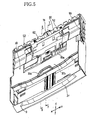
- the sheet-supply roller 6b of the sheet-supply unit 6 is constructed such that when the second sheet-supply cassette 30 takes the retracted or non-sheet-supply position, shown in Fig. 4, away from a sheet-supply path 9, the sheet-supply roller 6b contacts an upper surface of the uppermost one of the recording sheets P (not shown in Fig. 4) accommodated by the first sheet-supply cassette 3 and, when the second sheet-supply cassette 30 takes the advanced, sheet-supply position, shown in Fig. 5, near the sheet-supply path 9, the sheet-supply roller 6b contacts an upper surface of the uppermost one of the recording sheets P1 (not shown in Fig. 5) accommodated by the second sheet-supply cassette 30.
- the first sheet-supply cassette 3 can accommodate a large number of recording sheets P cut to have a large size such as A4 size, letter size, or legal size, such that the recording sheets P are stacked on each other on the bottom surface 3b thereof as a supporting surface and such that respective short sizes thereof extend in the main scanning direction.
- the first sheet-supply cassette 3 can accommodate, at the most, about one hundred plain sheets P having an about 10 mm height.
- the first sheet-supply cassette 3 has, in a front end portion thereof, a handle 3f that can be easily operated by fingers of a user when the first sheet-supply cassette 3 is inserted into, and removed from, the housing 2 via the front opening 2a thereof.
- the first sheet-supply cassette 3 is provided with a guide device including a left-side and a right-side guide member 34a, 34b that cooperate with each other to guide and position opposite long sides of each of the recording sheets P that extend parallel to the sheet-supply path 9.
- the left-side and right-side guide members 34a, 34b are movable or slideable relative to the bottom surface 3b in the Y direction, i.e., in a widthwise direction of the sheet-supply path 9, so as to adjust, i.e., increase or decrease a distance between the two members 34a, 34b and thereby position each recording sheet P in the Y direction.
- the two guide members 34a, 34b have respective racks, not shown, that are fixed to respective lower surfaces thereof, and the first sheet-supply cassette 3 has a pinion, not shown, that is rotatably supported by a lower surface of the bottom plate thereof at a center position in the Y direction.
- the respective racks of the two guide members 34a, 34b are meshed with the pinion such that the two guide members 34a, 34b cooperate with each other to center each recording sheet P with respect to the Y direction, i.e., cause a centerline of each recording sheet P with respect to the Y direction to coincide with a centerline of the first sheet-supply cassette 3 in the same direction.
- the first sheet-supply cassette 3 has, in a rear end portion thereof (i.e., a right-side end portion thereof in Fig. 2), an inclined sheet-separate (or guide) plate 8 for separating each one of the recording sheets P from the other recording sheets P, and separating each one of the recording sheets P1 from the other recording sheets P1.
- the inclined sheet-separate plate 8 supports, in a middle portion thereof in the Y direction, a sheet-separate body 8a that cooperates with the sheet-supply roller 6a provided at the lower end of the sheet-supply arm 6 to convey each one of the recording sheets P stacked in the first sheet-supply cassette 3 while separating the each one sheet P from the other sheets P, and convey each one of the recording sheets P1 stacked in the second sheet-supply cassette 30 while separating the each one sheet P1 from the other sheets P1.
- the thus separated recording sheet P or P1 is conveyed to the image recording portion 7 provided above the first and second sheet-supply cassettes 3, 30, via a curved guide member that partly defines a generally U-shaped portion of the sheet-convey path 9 and that is curved obliquely upward and frontward.
- a lower end of the curved guide member is located adjacent to an upper end of the inclined sheet-separate plate 8 or the sheet-separate body 8a.
- the recording sheet P or P1 on the upper surface of which images have been recorded by the image recording portion 7 is conveyed to the sheet discharging portion 10 communicating with the front opening 2a.
- the inclined sheet-separate plate 8 or the sheet-separate body 8a will be described in detail, later.
- the bottom surface 30a of the second sheet-supply cassette 30 is defined by a bottom plate of the cassette 30.
- the bottom surface 30a as a supporting surface supports a large number of stacked recording sheets P1 having a smaller size (e.g., postcard size or photograph-L size) than that of the recording sheets P stacked in the first sheet-supply cassette 3.
- the recording sheets P1 having the smaller size may be of a different sort (e.g., sheets for exclusive use with ink-jet printers, or glossy sheets for use as photographs) than that of the recording sheets P stacked in the first cassette 3.
- the bottom surface 30a is provided with a guide device 53 (i.e., two guide members) that positions the recording sheets P1 such that a centerline of each recording sheet P1 is aligned with a centerline of the sheet-supply path 9.
- the second sheet-supply cassette 30 is provided with a pivotable portion 51 that is pivotally connected to a rear end portion of the second cassette 30 via two hinge portions 52 such that the pivotable portion 51 is pivotable upward when new recording sheets P are inserted into the first sheet-supply cassette 3. More specifically described, in the state in which the pivotable portion 51 is held at the upward pivoted position, a front-side portion of the bottom surface 30a is opened more widely than a rear-side portion of the same 30a, so that the first sheet-supply cassette 3 is opened upward and the new recording sheets P can be easily inserted into the first cassette 3 through a front-side portion thereof.
- the second sheet-supply cassette 30 additionally includes a discharged-sheet receiving portion 30b that has a large width substantially equal to that of the first sheet-supply cassette 3 and that is integrally connected to a front end of the second cassette 30.
- the front-side portion (i.e., the discharged-sheet receiving portion 30b) of the second sheet-supply cassette 30, positioned at the non-sheet-supply position thereof, can entirely receive the large-size sheets P on which the images have been recorded.
- the second sheet-supply cassette 30 additionally includes two wing portions 57 that integrally project from the rear-side portion of the second cassette 30 in opposite directions, respectively, that are parallel to the Y direction, toward opposite side plates 3c, 3c of the first sheet-supply cassette 3.
- the two side plates 3c, 3c have respective guide rails 35, and the two wing portions 57 are slideable along the two guide rails 35, respectively, in the X direction. Since the two wing portions 57 are provided with respective stoppers, not shown, that prevent the wing portions 57 from coming off the corresponding guide rails 35, the second sheet-supply cassette 30 cannot easily come off the first sheet-supply cassette 3.
- the second sheet-supply cassette 30 has, at the front end thereof i.e., the front end of the discharged-sheet receiving portion 30b, a recess 30d that can be easily handled by the user. By handling the recess 30d, the user can easily move or slide the second sheet-supply cassette 30 relative to the first sheet-supply cassette 3, i.e., push (advance) the second cassette 30 to the advanced, sheet-supply position thereof and draw (retract) the second cassette 30 back to the retracted, non-sheet-supply position thereof.
- the second sheet-supply cassette 30 is advanceable and retractable relative to the first sheet-supply cassette 3, between the sheet-supply position thereof and the non-sheet-supply position thereof.
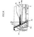
- the second cassette 30 is kept at the sheet-supply position thereof relative to the first cassette 3, by a sheet-supply-position (i.e., advanced-position) keeping device. More specifically described, as shown in Fig. 9, the second sheet-supply cassette 30 has two hook-like engaging portions 31 that project upward from the rear end of the bottom plate defining the bottom surface 30a.
- the two hook-like engaging portions 31 have respective grooves 31a formed in respective lower surfaces thereof. Meanwhile, as shown in Fig.
- the inclined sheet-separate plate 8 has a plurality of positioning holes 8b that are formed through a thickness thereof and are arranged in an array in the Y direction.
- the sheet-supply-position keeping device includes the two pairs of engaging portions 31 and positioning holes 8b that are arranged in the Y direction and are provided on either side of the sheet-separate body 8a in the same direction.
- the sheet-supply-position keeping device can reliably keep the second sheet-supply cassette 30 to the sheet-supply position thereof, and can prevent the same 30 from being moved out of position relative to the first sheet-supply cassette 3 in the upward or downward direction or the Y direction.
- the two hook-like engaging portions 31 can be considerably easily released from the engagement with the corresponding two positioning holes 8b.
- the sheet-supply arm 6a (or the sheet-supply roller 6b) of the sheet-supply unit 6 is constructed such that the arm 6a is pivoted upward and downward and accordingly the roller 6b is moved upward and downward, according to the advancing and retracting movements of each of the first and second sheet-supply cassettes 3, 30. More specifically described, a flat cam-follower member, not shown, integrally projects from the sheet-supply arm 6a, such that the cam-follower member extends parallel to the drive axis member 6d.
- the cam-follower member runs over a secondary cam surface 44 that is defined by an upper surface of one 30c of opposite side plates of the second sheet-supply cassette 30 and has variable height positions, and further reaches a position where the cam-follower member can engage a main cam surface 55 that is defined by an upper surface of a corresponding one of the opposite side plates 3c of the first sheet-supply cassette 3 and has variable height positions.
- the sheet-supply arm 6a is pivoted upward to take a substantially horizontal posture and allow the inclined sheet-separate plate 8 to pass below the sheet-supply roller 6b, and then the arm 6a is pivoted downward to cause the roller 6b to contact the uppermost one of the recording sheets P1 stacked on the bottom surface 30a of the second sheet-supply cassette 30 or the uppermost one of the recording sheets P stacked on the bottom surface 3b of the first sheet-supply cassette 3.
- the cam-follower member of the sheet-supply unit 6 is guided by the secondary cam surface 44 of the second cassette 30, so that the sheet-supply arm 6a is first pivoted upward and then pivoted downward.
- the sheet-supply roller 6b can contact the uppermost one of the recording sheets P1 stacked on the bottom surface 30a of the second sheet-supply cassette 30.
- the cam-follower member is guided by the secondary cam surface 44, so that the sheet-supply arm 6a is first pivoted upward and then pivoted downward.
- the sheet-supply roller 6b can contact the uppermost one of the recording sheets P stacked on the bottom surface 3b of the first cassette 3, without interfering with the recording sheets P1 stacked in the second sheet-supply cassette 30.
- the inclined sheet-separate plate 8 i.e., the inclined guide plate
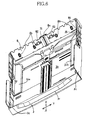
- the sheet-separate body 8a As shown in Fig. 6, the inclined sheet-separate plate 8 is provided in the rear end portion of the first sheet-supply cassette 3, such that the plate 8 extends in the Y direction parallel to the widthwise direction of the sheet-supply path 9.
- the sheet-separate plate 8 has a height higher than the highest possible position that can be taken by the recording sheets P1 accommodated by the second sheet-supply cassette 30.
- the inclined sheet-separate plate 8 and the sheet-separate body 8a, provided in the first sheet-supply cassette 3 are commonly used for separating the recording sheets P accommodated by the first sheet-supply cassette 3, and separating the recording sheets P1 accommodated by the second sheet-supply cassette 30.
- the second sheet-supply cassette 30 is provided on the first sheet-supply cassette 3. Therefore, respective lower portions of the inclined sheet-separate plate 8 and the sheet-separate body 8a are used for separating the recording sheets P accommodated by the first cassette 3; and respective upper portions of the sheet-separate plate 8 and the sheet-separate body 8a are used for separating the recording sheets P1 accommodated by the second cassette 30.
- each recording sheet P1 is conveyed along, and contacted with, the respective upper portions of the sheet-separate plate 8 and the sheet-separate body 8a, while being separated from the other recording sheets P1 by the cooperation of the upper portion of the sheet-separate body 8a and the sheet-supply roller 6b, and then is conveyed to the curved guide member.
- An inner (or upper) surface 8c of the inclined sheet-separate plate 8 that is opposed to respective leading ends of the two sorts of recording sheets P, P1 is convexly curved such that a central portion of the inner surface 8c of the sheet-separate plate 8 with respect to the widthwise direction of each recording sheet P, P1, i.e., portions of the inner surface 8c that are near the sheet-separate body 8a project, from opposite end portions of the inner surface 8c with respect to the same direction, toward the respective leading ends of respective central portions of the recording sheets P, P1 with respect to the same direction.
- the leading end of widthwise central portion of the uppermost recording sheet P (or P1) is reliably contacted or engaged with the sheet-separate body 8a and is separated from the other recording sheets P (or P1) before respective leading ends of widthwise opposite end portions of the uppermost recording sheet P (or P1) are contacted or engaged with the inner surface 8c of the plate 8.
- the sheet-separate body 8a has a plurality of sheet-separate portions 79 that project toward the respective leading ends of the recording sheets P, P1 and that are arranged in an array along the sheet-supply path 9.
- the sheet-separate body 8a is constituted by an elongate elastic body (e.g., a metallic plate spring).
- the sheet-separate body 8a includes a flat base portion 76; and an array of arm portions 77 that are formed by cutting a plurality of inner portions of the base portion 86 and bending the cut inner portions upward.
- Each of the arm portions 77 has, as a free end portion thereof, the sheet-separate portion 79 that has a generally V-shaped cross section and that is inclined by an acute angle, ⁇ 1 (Fig. 11A), relative to a downstream direction of the sheet-supply path 9.
- the sheet-separate body 8a includes a plurality of elastic leg portions 80 that are formed along two long sides of the flat base portion 76 such that the elastic leg portions 80 are inclined in an upstream direction of the sheet-supply path 9.
- the elastic leg portions 80 cooperate with each other to apply an elastic force (or a biasing force) to the sheet-separate portions 79 via the base portion 76. As shown in Fig.
- the inclined sheet-separate plate 8 has, in the central portion thereof with respect to the Y direction, a plurality of window holes through which the arm portions 77 or sheet-separate portions 79 of the sheet-separate body 8a, attached to a back surface of the sheet-separate plate 8, project to the inner side of the same 8.
- the elastic leg portions 80 is elastically deformed to permit a portion of the base portion 76 to displace toward the one leg portion 80 and thereby cause the each sheet P, P1 to displace relative to the underlying sheet or sheets P, P1.
- the inclined sheet-separate plate 8 supports, at a height position corresponding to an intermediate portion of the array of sheet-separate portions 79 with respect to the sheet-supply path 9, two rollers 60 each as a rotatable member that assists the conveying of each recording sheet P (but not the conveying of each recording sheet P1,). More specifically described, as shown in Fig. 11A, each of the two rollers 60 projects, by a distance, ⁇ H, in an inward direction from a plane tangential to the respective free ends of the sheet-separate portions 79. Preferably, the distance ⁇ H ranges from 0.5 mm, inclusive, to 1.0 mm, inclusive. In addition, as shown in Fig.
- the two rollers 60 are provided at a height position where the rollers 60 can engage all the recording sheets P (from the bottom one to the top one) accommodated by the first sheet-supply cassette 3 but cannot engage any of the recording sheets P1 (even the bottom one) accommodated by the second sheet-supply cassette 30. That is, the two rollers 60 are provided at the substantially same height position as the height position where the bottom plate (i.e., the bottom surface 30a) of the second cassette 30 is located.
- each recording sheet P supplied by the first cassette 3 is contacted or engaged with the rollers 60, so that the each recording sheet P is conveyed forward while being prevented from being contacted or engaged with downstream sheet-separate portions 79 that are located on a downstream side of the rollers 60 with respect to the sheet-supply path 9.
- Each of the rollers 60 has a cylindrical outer surface 60a a portion of which projects inward from the inner surface 8c of the inclined sheet-separate plate 8 such that a plane tangential to an upstream-side end of the projecting portion of the cylindrical outer surface 60a with respect to the sheet-supply path 9 is inclined by an acute angle, ⁇ 2, relative to the downstream direction of the sheet-supply path 9.
- the projecting portion of the cylindrical outer surface 60a is less than 50% of the entire cylindrical outer surface 60a.
- the sheet-separate portions 79 are continually arranged at substantially regular intervals of distance along the sheet-supply path 9, and the two rollers 60 are provided, on either side of the arranged sheet-separate portions 79, at respective positions that are symmetric with each other with respect to the array of portions 79 with respect to the widthwise direction of each recording sheet P, P1.
- each recording sheet P, P1 is engaged, with well balanced forces, with the two rollers 60.
- the positions where the rollers 60 are provided, and/or the total number of the rollers 60 may be changed.
- Fig. 11B shows a second embodiment of the present invention in which an array of sheet-separate portions 79 include upstream sheet-separate portions 79 corresponding to the recording sheets P accommodated by the first sheet-supply cassette 3, and downstream sheet-separate portions 79 corresponding to the recording sheets P1 accommodated by the second sheet-supply cassette 30, and a single roller 90 having a cylindrical outer surface 90a is provided in an increased space provided between the upstream sheet-separate portions 79 and the downstream sheet-separate portions 79 along the sheet-supply path 9.
- a single roller 90 having a cylindrical outer surface 90a is provided in an increased space provided between the upstream sheet-separate portions 79 and the downstream sheet-separate portions 79 along the sheet-supply path 9.
- the roller 90 projects, by the distance, ⁇ H, in an inward direction from a plane tangential to the respective free ends of all the sheet-separate portions 79.
- each recording sheet P can reliably contact or engage, at the widthwise central portion thereof, the roller 90 supported by the central portion of the inclined sheet-separate plate 8.
- the sheet-supply roller 6b contacts the uppermost one of the recording sheets P accommodated by the first sheet-supply cassette 3 and, when the sheet-supply roller 6b is driven or rotated, one or more upper recording sheets P including the uppermost recording sheet P is or are conveyed toward the sheet-separate body 8a.
- the leading end of the uppermost sheet P is engaged with the sheet-separate body 8a and is thereby separated from the other, underlying sheet or sheets P.
- the thus separated uppermost sheet P is conveyed downstream so that the leading end of the uppermost sheet P is then contacted with the rollers 60 or the roller 90. Since the rollers 60 or the roller 90 project or projects, by the distance ⁇ H, inward from the sheet-separate portions 79a, 79b toward the recording sheets P. Therefore, after each recording sheet P is contacted with the rollers 60 or the roller 90, the each sheet P is conveyed downstream while being prevented from being engaged with the downstream sheet-separate portions 79 that are located on the downstream side of the rollers 60 or the roller 90, i.e., while being kept away from the downstream portions 79.
- the sheet-supply roller 6b contacts the uppermost one of the recording sheets P1 accommodated by the second sheet-supply cassette 30 and, when the sheet-supply roller 6b is rotated, one or more upper recording sheets P1 including the uppermost recording sheet P1 is or are conveyed toward the sheet-separate body 8a.
- the leading end of the uppermost sheet P1 is engaged with the sheet-separate body 8a and is thereby separated from the other, underlying sheet or sheets P1.
- each of the recording sheets P1 accommodated by the second sheet-supply cassette 30 is reliably contacted or engaged with the downstream sheet-separate portions 79 that are located on the downstream side of the rollers 60 or the roller 90, and is thereby separated from the underlying sheet or sheets P1.
- each recording sheet P supplied from the first sheet-supply cassette 3 and separated from the other recording sheets P by the upstream sheet-separate portions 79 is unnecessarily contacted with the downstream sheet-separate top portions 79 provided for separating the recording sheets P1 accommodated by the second sheet-supply cassette 30. This leads to increasing a load or a force to convey each recording sheet P.
- the rollers 60 or the roller 90 are or is employed, and each recording sheet P supplied from the first sheet-supply cassette 3 and separated from the other recording sheets P is effectively prevented by the same 60, 90 from being contacted with the downstream sheet-separate portions 79 that are located on the downstream side of the same 60, 90. Therefore, the sheet-conveying load or force is not unnecessarily increased. This leads to decreasing the driving power applied to the sheet-supply roller 6b used to supply each recording sheet P, and thereby decreasing the size or capacity of the driving motor to drive or rotate the roller 6b. Thus, the sheet supplying apparatus can be produced at a decreased cost and can be disposed in a decreased space.
Landscapes
- Engineering & Computer Science (AREA)
- Mechanical Engineering (AREA)
- Sheets, Magazines, And Separation Thereof (AREA)
Abstract
Description
- The present application is based on
Japanese Patent Application No. 2005-285126 filed on September 29, 2005 - The present invention relates to a sheet supplying apparatus that supplies a plurality of recording sheets, one by one, while separating the recording sheets from each other.
- Generally, a conventional image recording device, such as a printer or a facsimile machine, includes an image recording portion and a sheet-supply cassette that accommodates a plurality of stacked recording sheets each as a recording medium, and supplies the recording sheets, one by one, from the sheet-supply cassette to the image recording portion so that the image recording portion may record an image on each recording sheet. For example, Patent Document 1 (i.e.,
Japanese Patent Application Publication No. 2004-149297 U.S. Patent Application Publication No. 2004-084831 A1 ) discloses a sheet supplying device including a sheet accommodating portion that accommodates a plurality of stacked recording sheets in their inclined postures; a sheet-supply roller that is pressed on the uppermost one of the stacked recording sheets; and a sheet separating portion that is supported by a bottom plate such that respective lower (i.e., leading) ends of the stacked recording sheets are held in contact with the sheet separating portion. The sheet separating portion includes a plurality of projecting portions that are arranged at regular intervals of distance, along a sheet-supply path along which each recording sheet is supplied; a plurality of pairs of arm portions each pair of which supports a corresponding one of the projecting portions, on either side of the one projecting portion; and a continuous base portion that continuously connects the arm portions to each other and thereby supports the arm portions. The sheet separating portion is held by a holder that is formed of a metallic plate and is fixed to the bottom plate, such that the projecting portions project by respective predetermined amounts through an elongate hole of the holder that is elongate along the sheet-supply path. When the sheet-supply roller, pressed on the uppermost one of the stacked recording sheets, is driven or rotated to convey the uppermost recording sheet, the leading end of the uppermost recording sheet pushes an appropriate one of the projecting portions, and consequently the one projecting portion is moved downward into the elongate hole of the holder because of elastic deformation of the corresponding arm portion. Since, however, the other recording sheets than the uppermost recording sheet are not moved because the respective leading ends thereof are engaged with the other projecting portions that remain projecting from the elongate hole, only the uppermost recording sheet is separated from the other recording sheets and is conveyed forward. - Meanwhile, recently, there is known an image recording device including a housing and a plurality of sheet-supply cassettes that accommodate different sorts of recording sheets, respectively, and that are insertable into, and removable from, the housing. For example, Patent Document 2 (i.e.,
Japanese Patent Application Publication No. 11-59925 - However, the sheet supplying device disclosed by
Patent Document 2 does not employ a sheet separating portion as disclosed by Patent Document 1 in such a manner that the sheet separating portion is applied to the outlet opening of the first sheet-supply cassette and is commonly used to separate, from each other, the recording sheets supplied from each of the first and second sheet-supply cassettes. Thus, the conventional sheet supplying device does not meet two requirements, i.e., the decreasing of size of the device as a whole and the increasing of accuracy of the supplying of recording sheets. - In the above-described technical background, the present invention has been developed. It is therefore an object of the present invention to solve at least one of the above-indicated problems. It is another object of the present invention to provide a sheet supplying apparatus that employs a plurality of sheet accommodating portions each of which accommodates a plurality of stacked recording sheets and that supplies, from each of the two sheet accommodating portions, the recording sheets while separating the sheets from each other. It is another object of the present invention to provide a sheet supplying apparatus that enjoys a simplified construction and/or a decreased production cost.
- According to the present invention, there is provided a sheet supplying apparatus for supplying a plurality of recording sheets, one by one, along a sheet-supply path, the apparatus comprising a first accommodating portion which has a first supporting surface, which accommodates a plurality of first recording sheets stacked on each other on the first supporting surface, and from which the first recording sheets are supplied, one by one, along the sheet-supply path; a second accommodating portion which has a second supporting surface, which accommodates a plurality of second recording sheets stacked on each other on the second supporting surface, and from which the second recording sheets are supplied, one by one, along the sheet-supply path; at least one supplying member which contacts an uppermost one of the first recording sheets accommodated by the first accommodating portion, so as to supply the uppermost first recording sheet from the first accommodating portion, and additionally contacts an uppermost one of the second recording sheets accommodated by the second accommodating portion, so as to supply the uppermost second recording sheet from the second accommodating portion; a separating device which cooperates with the at least one supplying member to separate the first recording sheets from each other and separate the second recording sheets from each other, wherein the separating device includes (A) an inclined guide plate which is provided at an upstream-side end portion of the sheet-supply path such that the inclined guide plate extends in a widthwise direction of the sheet-supply path, which is inclined relative to each of the first and second supporting surfaces such that the inclined guide plate is opposed to respective leading ends of respective greatest possible numbers of the first and second recording sheets that can be accommodated by the first and second accommodating portions, and which guides a movement of each of the first and second recording sheets along the sheet-supply path, and (B) a sheet-separate body which is supported by the inclined guide plate and which includes a plurality of sheet-separate portions arranged in at least one array along the sheet-supply path such that the sheet-separate portions project from the inclined guide plate toward the first and second recording sheets accommodated by the first and second accommodating portions; and at least one contact preventing portion which projects toward the first and second recording sheets, beyond respective free ends of the sheet-separate portions, and which is provided at a position corresponding to an intermediate portion of the at least one array of sheet-separate portions with respect to the sheet-supply path, and assuring that the at least one contact preventing portion prevents each of the first recording sheets supplied from the first accommodating portion, from contacting at least one sheet-separate portion of a downstream portion of the at least one array of sheet-separate portions that is located on a downstream side of the at least one contact preventing portion with respect to the sheet-supply path, and allows each of the second recording sheets supplied from the second accommodating portion, to contact the downstream portion of the at least one array of sheet-separate portions. The present apparatus may comprise, as the at least one supplying member, a single supplying member commonly used with the first and second accommodating portions, or two supplying members that exclusively used with the first and second accommodating portions, respectively.
- In the present sheet supplying apparatus, the inclined guide plate and the sheet-separate body are commonly used for supplying the first recording sheets from the first accommodating portion and supplying the second recording sheets from the second accommodating portion. Thus, the first recording sheets accommodated by the first accommodating portion can be supplied while being reliably separated from each other, and the second recording sheets accommodated by the second accommodating portion can be supplied while being reliably separated from each other. In addition, since the inclined guide plate and the sheet-separate body are common the first and second accommodating portions, the present apparatus enjoys a simpler construction and a lower production cost than a case where individual inclined guide plates and individual sheet-separate bodies are provided for the first and second accommodating portions, respectively.
- Moreover, if the present sheet supplying apparatus does not employ the contact preventing portion, then the uppermost first recording sheet that has been separated from the other first recording sheets by the sheet-separate portions of the upstream portion of the array of sheet-separate portions with respect to the sheet-supply path, continues to contact the sheet-separate portions of the downstream portion of the array. This leads to increasing the load of conveying the uppermost first recording sheet. For example, a driving force used to drive the supplying member needs to be increased. However, the present apparatus employs the contact preventing portion provided at the position corresponding to the intermediate portion of the array of sheet-separate portions and assuring that the contact preventing portion prevents each of the first recording sheets supplied from the first accommodating portion, from contacting the downstream portion of the array of sheet-separate portions that is located on the downstream side of the contact preventing portion with respect to the sheet-supply path. Thus, each of the first recording sheets accommodated by the first accommodating portion can be supplied without increasing the load of conveying thereof. Consequently, for example, the driving force used to drive the supplying member need not be increased, a capacity or size of a drive source to drive the supplying member need not be increased, or a cost of the drive source need not be increased.
- The above and optional objects, features, and advantages of the present invention will be better understood by reading the following detailed description of the preferred embodiments of the invention when considered in conjunction with the accompanying drawings, in which:
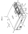
- Fig. 1 is a perspective view of an image recording apparatus including a sheet supplying apparatus to which the present invention is applied;
- Fig. 2 is a cross-sectional view of the image recording apparatus;
- Fig. 3 is a perspective view of a lower portion of the image recording apparatus with an upper portion thereof being removed;
- Fig. 4 is a perspective view of a first sheet-supply cassette of the image recording apparatus with a second sheet-supply cassette thereof being positioned at its retracted position, i.e., non-sheet-supply position;
- Fig. 5 is a perspective view of the first sheet-supply cassette with the second sheet-supply cassette being positioned at its advanced position, i.e., sheet-supply position;
- Fig. 6 is a perspective view of the first sheet-supply cassette with the second sheet-supply cassette being removed;
- Fig. 7 is a cross-section view of the first sheet-supply cassette, taken along 7 - 7 in Fig. 5;
- Fig. 8 is another cross-section view of the first sheet-supply cassette, taken along 8 - 8 in Fig. 5;
- Fig. 9 is a longitudinal cross-section view showing an advanced-position keeping device that keeps the first sheet-supply cassette to the advanced position thereof relative to the second sheet-supply cassette;
- Fig. 10 is a perspective view of a sheet-separate body attached to an inclined sheet-separate (or guide) plate of the first sheet-supply cassette;
- Fig. 11A is a longitudinal cross-section view showing a state in which the sheet-separate body is attached to the inclined sheet-separate plate; and
- Fig. 11B is a longitudinal cross-section view corresponding to Fig. 11A, and showing another sheet supplying apparatus in which another sheet-separate body is attached to another inclined sheet-separate plate.
- Hereinafter, there will be described a basic embodiment of the present invention by reference to Figs. 1 through 10 and 11A. The present embodiment relates to a sheet supplying apparatus that is employed by an image recording apparatus 1, i.e., a "multi-function device (MFD)" having a printer function, a copier function, a scanner function, and a facsimile-machine function. As shown in Figs. 1 and 2, the image recording apparatus 1 includes a
housing 2 that is formed by injection molding of a synthetic resin and constitutes a main frame of the recording apparatus 1. In a bottom portion of thehousing 2, there is provided a first sheet-supply cassette 3, described later, that is insertable into, and removable from, thehousing 2 via a front opening 2a thereof. A second sheet-supply cassette 30, also described later, is connectable to, or placeable on, a top portion of the first sheet-supply cassette 3, such that the second sheet-supply cassette 30 is advanceable to a sheet-supply position thereof and is retractable to a non-sheet-supply position thereof. In the following description, a portion, a side, or an end of the recording apparatus 1 where the opening 2a is provided will be referred to as the "front" portion, side, or end thereof and a portion, a side, or an end of the apparatus 1 that is opposite to the front portion, side, or end thereof will be referred to as the "rear" portion, side, or end thereof. - In a top portion of the
housing 2, there is provided animage reading device 12 that is used for each of the copier function and the facsimile-machine function, i.e., reading an original image from an original sheet. Theimage reading device 12 is constructed such that thereading device 12 is pivotable about an axis portion, not shown, located along one lateral side of thehousing 2, so that thereading device 12 can be opened upward and closed downward. Acover member 13 that can cover the original sheet placed on an upper surface of theimage reading device 12, is attached to thereading device 12 such that a rear end of thecover member 13 is pivotable about anaxis portion 12a located along a rear end of thereading device 12, so that thecover member 13 can be opened upward and closed downward. - In the top portion of the
housing 2, anoperation panel 14 is provided in front of theimage reading device 12. Theoperation panel 14 includes various sorts of operation keys and a liquid crystal display (LCD). Theimage reading device 12 includes an original-sheetsupport glass plate 16 that supports, on an upper surface thereof, the original sheet and can be covered by thecover member 13 that can be opened upward to allow the original sheet to be placed on theglass plate 16. A contact image sensor (CIS) 17 is provided below thesupport glass plate 16, such that theimage sensor 17 can be reciprocated along aguide shaft 17a in a main scanning direction, i.e., a Y direction shown in Fig. 1, so as to read the original image from the original sheet. The Y direction is perpendicular to the drawing sheet of Fig. 2. - Below the
image reading device 12 and theoperation panel 14, there are provided an image recording portion 7, asheet discharging portion 10, and an ink storing portion 15 (Fig. 3) within respective projected areas of theimage reading device 12 and theoperation panel 14 that are projected in a vertically downward direction that is perpendicular to the Y direction and also to an X direction perpendicular to the Y direction. Theink storing portion 15 is provided on one side of thesheet discharging portion 10. - As shown in Figs. 2 and 3, the image recording device 7 is provided between an upward opening box-
like frame 21, and a first and a second elongate plate-like guide member like frame 21 and extend in the Y direction (i.e., the main scanning direction). Thefirst guide member 22 is located on an upstream side of thesecond guide member 23 in a sheet-convey direction, A. The recording device 7 includes acarriage 5 that carries an ink-jet recording head 4 and bridges the twoguide members carriage 5 is slideable or reciprocateable on the same 22, 23. - A
timing belt 24 is wound on pulleys fixed to an upper surface of thesecond guide member 23, located on the downstream side in the sheet-convey direction A, such that thetiming belt 24 extends in the main scanning direction (i.e., the Y direction) and is driven to reciprocate thecarriage 5. A carriage (CR) motor 25 that drives thetiming belt 24 is fixed to a lower surface of thesecond guide member 23. In the present embodiment, theCR motor 25 is provided by a DC (direct current) motor. However, the DC motor may be replaced with a stepper motor or other sorts of electric motors. Thesecond guide member 23 is provided with a belt-like encoder strip, not shown, that extends in the main scanning direction and detects a current position of thecarriage 5 in the same direction. The belt-like encoder strip is disposed such that a detection plane thereof having a plurality of slits arranged at regular intervals in the main scanning direction is vertical. - As shown in Figs. 2 and 3, a
flat platen 26 extends in the Y direction such that theplaten 26 is opposed to a lower surface of therecording head 4 mounted on thecarriage 5, and theplaten 26 is fixed to an upper portion of abottom plate 21b of the box-like frame 21 at a position between the first andsecond guide members - A
partition plate 29 is formed of the synthetic resin, integrally with thehousing 2, and is located above thesheet discharging portion 10, at a height position substantially level with the bottom plate 21a of the box-like frame 21, such that thepartition plate 29 extends from the lower surface of the downstream-side,second guide member 23 to thefront opening 2a of thehousing 2 that also functions as a sheet-discharge outlet. - As shown in Fig. 3, the
ink storing portion 15 opens upward through an upper opening of thehousing 2, and accommodates four ink cartridges 19 (19a, 19b, 19c, 19d) that respectively store four inks, e.g., black (BK), cyan (C), magenta (M), and yellow inks (Y), for the purpose of recording a full-color image. Each of the four ink cartridges 19 has a substantially rectangular parallelepiped shape having a small area in its plan view, and a great height. The four ink cartridges 19 are arranged in an array in the X direction, and each ink cartridge 19 is attachable to, and detachable from, theink storing portion 15 through the upper opening of thehousing 2. - The four ink cartridges 19 are connected to the
recording head 4 via respective flexible ink-supply tubes 20, so as to supply the respective inks to the same 4. However, in the case where more than four sorts of inks (e.g., six or eight inks) are used, theink storing portion 15 is modified to accommodate the corresponding number of ink cartridges 19, and those ink cartridges 19 are connected to therecording head 4 via the corresponding number of flexible ink-supply tubes 20, respectively. - As shown in Fig. 3, respective base end portions of the four flexible ink-
supply tubes 20 that are near the corresponding ink cartridges 19 are bundled up with each other, at a position near one end of theink storing portion 15. Respective intermediate portions of the four flexible ink-supply tubes 20 are supported by a substantially horizontal, upper surface of thepartition plate 29, so as to extend in the Y direction from one end (i.e., a left-side end in Fig. 3) of theplate 29 to the opposite end (i.e., a right-side end in Fig. 3) of the same 29. The bundled base end portions of the four ink-supply tubes 20 are arranged, side by side, on the upper surface of thepartition plate 29. - The image recording portion 7 additionally includes an ink receiving portion, not shown, and a maintenance unit, not shown, that are provided in respective opposite areas outside or beyond an image recording area corresponding to a width (i.e., a length of a short side) of each recording sheet as a sort of recording medium that is accommodated by the first sheet-
supply cassette 3. At a flushing position opposed to the ink receiving portion, therecording head 4 periodically ejects or "flushes" droplets of inks during an image recording operation, for the purpose of preventing clogging of ink-ejection nozzles of therecording head 4, and the ink receiving portion receives the droplets of inks ejected by the nozzles of thehead 4. At a waiting position opposed to the maintenance unit, a capping portion of the maintenance unit covers the lower surface (i.e., nozzle-support surface) of therecording head 4 so as to suck an arbitrarily selected one of the different inks. In addition, the maintenance unit carries out a recovering operation to remove air bubbles from a buffer tank, not shown, of therecording head 4. When thecarriage 5 is moved in the Y direction along the maintenance unit, a cleaner (e.g., a wiper blade) of the maintenance unit wipes and cleans the nozzle-support surface of therecording head 4. - The
recording head 4 mounted on thecarriage 5 ejects, from arbitrarily selected ones of the ink-ejection nozzles thereof, droplets of inks in response to command signals supplied thereto from a control portion, not shown, that is supported by thehousing 2 at a position distant from thecarriage 5. As shown in Fig. 3, a flexibleflat cable 40 that transmits the command signals from the control portion to therecording head 4, is provided such that the flexibleflat cable 40 extends substantially parallel to the flexible ink-supply tubes 20, in a movement area in which thetubes 20 are moved when thecarriage 5 is reciprocated in the main scanning direction. - As shown in Fig. 2, on an upstream side of the
platen 26 in the sheet-convey direction A, there are provided a pair of resister (conveyor)rollers 27 that cooperate with each other to convey each recording sheet to an upper surface of theplaten 26; and on a downstream side of theplaten 26, there are provided a sheet-discharge roller 28 and a spur roller, not shown, that cooperate with each other to convey each recording sheet on which an image has been recorded, to thesheet discharging portion 10. - Next, a construction of the sheet supplying apparatus will be described. In the present embodiment, the sheet supplying apparatus includes two sheet-supply cassettes, i.e., the first and second sheet-
supply cassettes supply cassette 3 as a first accommodating portion has abottom surface 3b that supports many recording sheets P stacked on each other. A sheet-supply unit 6 supplies, from the first sheet-supply cassette 3, the recording sheets P, one by one, to the image recording portion 7. In addition, the second sheet-supply cassette 30 is provided above thebottom surface 3b of the first sheet-supply cassette 3, such that the second sheet-supply cassette 30 is advanceable and retractable relative to the first sheet-supply cassette 3. The second sheet-supply cassette 30 as a second accommodating portion has abottom surface 30a that supports many recording sheets P1 (Fig. 9) that are stacked on each other and that have a size smaller than that of the recording sheets P accommodated by the first sheet-supply cassette 3. - As shown in Fig. 2, the sheet-
supply unit 6 includes adrive axis member 6d that is rotatably supported by the two end plates (not shown) of the box-like frame 21 and a pair of axis-member support plates, not shown. One end portion of thedrive axis member 6d is inserted in a base end portion of a sheet-supply arm 6a of the sheet-supply unit 6, such that the one end portion of themember 6d projects laterally from thearm 6a. When thedrive axis member 6d is driven or rotated by an electric motor, not shown, under control of the above-described control portion (not shown), a sheet-supply roller 6b as a common supplying member is rotated in a forward direction (i.e., counterclockwise in Fig. 2) via agear transmission device 6c provided in the sheet-supply arm 6a. In addition, a biasing means (e.g., a torsion coil spring), not shown, biases the sheet-supply arm 6a in a downward direction. - The sheet-
supply roller 6b of the sheet-supply unit 6 is constructed such that when the second sheet-supply cassette 30 takes the retracted or non-sheet-supply position, shown in Fig. 4, away from a sheet-supply path 9, the sheet-supply roller 6b contacts an upper surface of the uppermost one of the recording sheets P (not shown in Fig. 4) accommodated by the first sheet-supply cassette 3 and, when the second sheet-supply cassette 30 takes the advanced, sheet-supply position, shown in Fig. 5, near the sheet-supply path 9, the sheet-supply roller 6b contacts an upper surface of the uppermost one of the recording sheets P1 (not shown in Fig. 5) accommodated by the second sheet-supply cassette 30. - The first sheet-
supply cassette 3 can accommodate a large number of recording sheets P cut to have a large size such as A4 size, letter size, or legal size, such that the recording sheets P are stacked on each other on thebottom surface 3b thereof as a supporting surface and such that respective short sizes thereof extend in the main scanning direction. The first sheet-supply cassette 3 can accommodate, at the most, about one hundred plain sheets P having an about 10 mm height. The first sheet-supply cassette 3 has, in a front end portion thereof, ahandle 3f that can be easily operated by fingers of a user when the first sheet-supply cassette 3 is inserted into, and removed from, thehousing 2 via thefront opening 2a thereof. - As shown in Fig. 6, the first sheet-
supply cassette 3 is provided with a guide device including a left-side and a right-side guide member supply path 9. The left-side and right-side guide members bottom surface 3b in the Y direction, i.e., in a widthwise direction of the sheet-supply path 9, so as to adjust, i.e., increase or decrease a distance between the twomembers guide members supply cassette 3 has a pinion, not shown, that is rotatably supported by a lower surface of the bottom plate thereof at a center position in the Y direction. The respective racks of the twoguide members guide members supply cassette 3 in the same direction. - The first sheet-
supply cassette 3 has, in a rear end portion thereof (i.e., a right-side end portion thereof in Fig. 2), an inclined sheet-separate (or guide)plate 8 for separating each one of the recording sheets P from the other recording sheets P, and separating each one of the recording sheets P1 from the other recording sheets P1. As shown in Figs 4 through 6, the inclined sheet-separate plate 8 supports, in a middle portion thereof in the Y direction, a sheet-separate body 8a that cooperates with the sheet-supply roller 6a provided at the lower end of the sheet-supply arm 6 to convey each one of the recording sheets P stacked in the first sheet-supply cassette 3 while separating the each one sheet P from the other sheets P, and convey each one of the recording sheets P1 stacked in the second sheet-supply cassette 30 while separating the each one sheet P1 from the other sheets P1. The thus separated recording sheet P or P1 is conveyed to the image recording portion 7 provided above the first and second sheet-supply cassettes path 9 and that is curved obliquely upward and frontward. A lower end of the curved guide member is located adjacent to an upper end of the inclined sheet-separate plate 8 or the sheet-separate body 8a. The recording sheet P or P1 on the upper surface of which images have been recorded by the image recording portion 7 is conveyed to thesheet discharging portion 10 communicating with thefront opening 2a. The inclined sheet-separate plate 8 or the sheet-separate body 8a will be described in detail, later. - As shown in Figs. 4 and 5, the
bottom surface 30a of the second sheet-supply cassette 30 is defined by a bottom plate of thecassette 30. Thebottom surface 30a as a supporting surface supports a large number of stacked recording sheets P1 having a smaller size (e.g., postcard size or photograph-L size) than that of the recording sheets P stacked in the first sheet-supply cassette 3. The recording sheets P1 having the smaller size may be of a different sort (e.g., sheets for exclusive use with ink-jet printers, or glossy sheets for use as photographs) than that of the recording sheets P stacked in thefirst cassette 3. Thebottom surface 30a is provided with a guide device 53 (i.e., two guide members) that positions the recording sheets P1 such that a centerline of each recording sheet P1 is aligned with a centerline of the sheet-supply path 9. - The second sheet-
supply cassette 30 is provided with apivotable portion 51 that is pivotally connected to a rear end portion of thesecond cassette 30 via twohinge portions 52 such that thepivotable portion 51 is pivotable upward when new recording sheets P are inserted into the first sheet-supply cassette 3. More specifically described, in the state in which thepivotable portion 51 is held at the upward pivoted position, a front-side portion of thebottom surface 30a is opened more widely than a rear-side portion of the same 30a, so that the first sheet-supply cassette 3 is opened upward and the new recording sheets P can be easily inserted into thefirst cassette 3 through a front-side portion thereof. - The second sheet-
supply cassette 30 additionally includes a discharged-sheet receiving portion 30b that has a large width substantially equal to that of the first sheet-supply cassette 3 and that is integrally connected to a front end of thesecond cassette 30. In the case where recording sheets P having a large size are stacked in the first sheet-supply cassette 3 and are used to record images thereon, the front-side portion (i.e., the discharged-sheet receiving portion 30b) of the second sheet-supply cassette 30, positioned at the non-sheet-supply position thereof, can entirely receive the large-size sheets P on which the images have been recorded. - The second sheet-
supply cassette 30 additionally includes twowing portions 57 that integrally project from the rear-side portion of thesecond cassette 30 in opposite directions, respectively, that are parallel to the Y direction, towardopposite side plates supply cassette 3. The twoside plates respective guide rails 35, and the twowing portions 57 are slideable along the twoguide rails 35, respectively, in the X direction. Since the twowing portions 57 are provided with respective stoppers, not shown, that prevent thewing portions 57 from coming off thecorresponding guide rails 35, the second sheet-supply cassette 30 cannot easily come off the first sheet-supply cassette 3. - The second sheet-
supply cassette 30 has, at the front end thereof i.e., the front end of the discharged-sheet receiving portion 30b, arecess 30d that can be easily handled by the user. By handling therecess 30d, the user can easily move or slide the second sheet-supply cassette 30 relative to the first sheet-supply cassette 3, i.e., push (advance) thesecond cassette 30 to the advanced, sheet-supply position thereof and draw (retract) thesecond cassette 30 back to the retracted, non-sheet-supply position thereof. - Thus, the second sheet-
supply cassette 30 is advanceable and retractable relative to the first sheet-supply cassette 3, between the sheet-supply position thereof and the non-sheet-supply position thereof. Thesecond cassette 30 is kept at the sheet-supply position thereof relative to thefirst cassette 3, by a sheet-supply-position (i.e., advanced-position) keeping device. More specifically described, as shown in Fig. 9, the second sheet-supply cassette 30 has two hook-likeengaging portions 31 that project upward from the rear end of the bottom plate defining thebottom surface 30a. The two hook-likeengaging portions 31 haverespective grooves 31a formed in respective lower surfaces thereof. Meanwhile, as shown in Fig. 6, the inclined sheet-separate plate 8 has a plurality ofpositioning holes 8b that are formed through a thickness thereof and are arranged in an array in the Y direction. When the second sheet-supply cassette 30 is pushed toward the advanced, sheet-supply position thereof, the two hook-likeengaging portions 31 engage the corresponding twopositioning holes 8b, such that therespective grooves 31a of the twoengaging portions 31 fit on respective portions of the inclined sheet-separate plate 8 that define respective lower portions of the twopositioning holes 8b. The sheet-supply-position keeping device includes the two pairs of engagingportions 31 andpositioning holes 8b that are arranged in the Y direction and are provided on either side of the sheet-separate body 8a in the same direction. Thus, the sheet-supply-position keeping device can reliably keep the second sheet-supply cassette 30 to the sheet-supply position thereof, and can prevent the same 30 from being moved out of position relative to the first sheet-supply cassette 3 in the upward or downward direction or the Y direction. However, when the second sheet-supply cassette 30 is retracted toward the non-sheet-supply position thereof by the user, the two hook-likeengaging portions 31 can be considerably easily released from the engagement with the corresponding twopositioning holes 8b. - The sheet-
supply arm 6a (or the sheet-supply roller 6b) of the sheet-supply unit 6 is constructed such that thearm 6a is pivoted upward and downward and accordingly theroller 6b is moved upward and downward, according to the advancing and retracting movements of each of the first and second sheet-supply cassettes supply arm 6a, such that the cam-follower member extends parallel to thedrive axis member 6d. The cam-follower member runs over a secondary cam surface 44 that is defined by an upper surface of one 30c of opposite side plates of the second sheet-supply cassette 30 and has variable height positions, and further reaches a position where the cam-follower member can engage amain cam surface 55 that is defined by an upper surface of a corresponding one of theopposite side plates 3c of the first sheet-supply cassette 3 and has variable height positions. - When the first and second sheet-
supply cassettes housing 2, the cam-follower member of the sheet-supply unit 6 is guided by themain cam surface 55 of thefirst cassette 3, irrespective of whether thesecond cassette 30 may be currently positioned at the sheet-supply position thereof or the non-sheet-supply position thereof relative to thefirst cassette 3. First, the sheet-supply arm 6a is pivoted upward to take a substantially horizontal posture and allow the inclined sheet-separate plate 8 to pass below the sheet-supply roller 6b, and then thearm 6a is pivoted downward to cause theroller 6b to contact the uppermost one of the recording sheets P1 stacked on thebottom surface 30a of the second sheet-supply cassette 30 or the uppermost one of the recording sheets P stacked on thebottom surface 3b of the first sheet-supply cassette 3. - In the state in which the first sheet-
supply cassette 3 is set at a sheet-supply position thereof in thehousing 2, if the second sheet-supply cassette 30 is advanced from the non-sheet-supply position thereof to the sheet-supply position thereof, the cam-follower member of the sheet-supply unit 6 is guided by the secondary cam surface 44 of thesecond cassette 30, so that the sheet-supply arm 6a is first pivoted upward and then pivoted downward. Thus, the sheet-supply roller 6b can contact the uppermost one of the recording sheets P1 stacked on thebottom surface 30a of the second sheet-supply cassette 30. On the other hand, if thesecond cassette 30 is retracted from the sheet-supply position thereof to the non-sheet-supply position thereof, the cam-follower member is guided by the secondary cam surface 44, so that the sheet-supply arm 6a is first pivoted upward and then pivoted downward. Thus, the sheet-supply roller 6b can contact the uppermost one of the recording sheets P stacked on thebottom surface 3b of thefirst cassette 3, without interfering with the recording sheets P1 stacked in the second sheet-supply cassette 30. - Next, there will be described respective constructions of the inclined sheet-separate plate 8 (i.e., the inclined guide plate) and the sheet-
separate body 8a. As shown in Fig. 6, the inclined sheet-separate plate 8 is provided in the rear end portion of the first sheet-supply cassette 3, such that theplate 8 extends in the Y direction parallel to the widthwise direction of the sheet-supply path 9. In addition, as shown in Fig. 9, the sheet-separate plate 8 has a height higher than the highest possible position that can be taken by the recording sheets P1 accommodated by the second sheet-supply cassette 30. That is, the inclined sheet-separate plate 8 and the sheet-separate body 8a, provided in the first sheet-supply cassette 3, are commonly used for separating the recording sheets P accommodated by the first sheet-supply cassette 3, and separating the recording sheets P1 accommodated by the second sheet-supply cassette 30. - The second sheet-
supply cassette 30 is provided on the first sheet-supply cassette 3. Therefore, respective lower portions of the inclined sheet-separate plate 8 and the sheet-separate body 8a are used for separating the recording sheets P accommodated by thefirst cassette 3; and respective upper portions of the sheet-separate plate 8 and the sheet-separate body 8a are used for separating the recording sheets P1 accommodated by thesecond cassette 30. Thus, each recording sheet P that has been separated from the other recording sheets P by the cooperation of the lower portion of the sheet-separate body 8a and the sheet-supply roller 6b, is conveyed to the curved guide member defining the U-shaped portion of the sheet-conveypath 9, after having passed by the respective upper portions of the sheet-separate plate 8 and the sheet-separate body 8a that correspond to the recording sheets P1 accommodated by thesecond cassette 30. On the other hand, each recording sheet P1 is conveyed along, and contacted with, the respective upper portions of the sheet-separate plate 8 and the sheet-separate body 8a, while being separated from the other recording sheets P1 by the cooperation of the upper portion of the sheet-separate body 8a and the sheet-supply roller 6b, and then is conveyed to the curved guide member. - An inner (or upper)
surface 8c of the inclined sheet-separate plate 8 that is opposed to respective leading ends of the two sorts of recording sheets P, P1 is convexly curved such that a central portion of theinner surface 8c of the sheet-separate plate 8 with respect to the widthwise direction of each recording sheet P, P1, i.e., portions of theinner surface 8c that are near the sheet-separate body 8a project, from opposite end portions of theinner surface 8c with respect to the same direction, toward the respective leading ends of respective central portions of the recording sheets P, P1 with respect to the same direction. Since theinner surface 8c of the inclined sheet-separate plate 8 is a convexly curved surface, the leading end of widthwise central portion of the uppermost recording sheet P (or P1) is reliably contacted or engaged with the sheet-separate body 8a and is separated from the other recording sheets P (or P1) before respective leading ends of widthwise opposite end portions of the uppermost recording sheet P (or P1) are contacted or engaged with theinner surface 8c of theplate 8. - As shown in Figs. 6 and 10, the sheet-
separate body 8a has a plurality of sheet-separate portions 79 that project toward the respective leading ends of the recording sheets P, P1 and that are arranged in an array along the sheet-supply path 9. The sheet-separate body 8a is constituted by an elongate elastic body (e.g., a metallic plate spring). The sheet-separate body 8a includes aflat base portion 76; and an array ofarm portions 77 that are formed by cutting a plurality of inner portions of the base portion 86 and bending the cut inner portions upward. Each of thearm portions 77 has, as a free end portion thereof, the sheet-separate portion 79 that has a generally V-shaped cross section and that is inclined by an acute angle, θ1 (Fig. 11A), relative to a downstream direction of the sheet-supply path 9. In addition, the sheet-separate body 8a includes a plurality ofelastic leg portions 80 that are formed along two long sides of theflat base portion 76 such that theelastic leg portions 80 are inclined in an upstream direction of the sheet-supply path 9. Theelastic leg portions 80 cooperate with each other to apply an elastic force (or a biasing force) to the sheet-separate portions 79 via thebase portion 76. As shown in Fig. 11A, the inclined sheet-separate plate 8 has, in the central portion thereof with respect to the Y direction, a plurality of window holes through which thearm portions 77 or sheet-separate portions 79 of the sheet-separate body 8a, attached to a back surface of the sheet-separate plate 8, project to the inner side of the same 8. When the leading end of each of the recording sheets P, P1 contacts at least one of the sheet-separate portions 79, at least one of theelastic leg portions 80 is elastically deformed to permit a portion of thebase portion 76 to displace toward the oneleg portion 80 and thereby cause the each sheet P, P1 to displace relative to the underlying sheet or sheets P, P1. - As shown in Figs. 6 and 11A, the inclined sheet-
separate plate 8 supports, at a height position corresponding to an intermediate portion of the array of sheet-separate portions 79 with respect to the sheet-supply path 9, tworollers 60 each as a rotatable member that assists the conveying of each recording sheet P (but not the conveying of each recording sheet P1,). More specifically described, as shown in Fig. 11A, each of the tworollers 60 projects, by a distance, ΔH, in an inward direction from a plane tangential to the respective free ends of the sheet-separate portions 79. Preferably, the distance ΔH ranges from 0.5 mm, inclusive, to 1.0 mm, inclusive. In addition, as shown in Fig. 5, the tworollers 60 are provided at a height position where therollers 60 can engage all the recording sheets P (from the bottom one to the top one) accommodated by the first sheet-supply cassette 3 but cannot engage any of the recording sheets P1 (even the bottom one) accommodated by the second sheet-supply cassette 30. That is, the tworollers 60 are provided at the substantially same height position as the height position where the bottom plate (i.e., thebottom surface 30a) of thesecond cassette 30 is located. Thus, only each recording sheet P supplied by thefirst cassette 3 is contacted or engaged with therollers 60, so that the each recording sheet P is conveyed forward while being prevented from being contacted or engaged with downstream sheet-separate portions 79 that are located on a downstream side of therollers 60 with respect to the sheet-supply path 9. Each of therollers 60 has a cylindrical outer surface 60a a portion of which projects inward from theinner surface 8c of the inclined sheet-separate plate 8 such that a plane tangential to an upstream-side end of the projecting portion of the cylindrical outer surface 60a with respect to the sheet-supply path 9 is inclined by an acute angle, θ2, relative to the downstream direction of the sheet-supply path 9. Preferably, the projecting portion of the cylindrical outer surface 60a is less than 50% of the entire cylindrical outer surface 60a. - In the present embodiment, as shown in Fig. 6, the sheet-
separate portions 79 are continually arranged at substantially regular intervals of distance along the sheet-supply path 9, and the tworollers 60 are provided, on either side of the arranged sheet-separate portions 79, at respective positions that are symmetric with each other with respect to the array ofportions 79 with respect to the widthwise direction of each recording sheet P, P1. Thus, each recording sheet P, P1 is engaged, with well balanced forces, with the tworollers 60. However, the positions where therollers 60 are provided, and/or the total number of therollers 60 may be changed. - Fig. 11B shows a second embodiment of the present invention in which an array of sheet-
separate portions 79 include upstream sheet-separate portions 79 corresponding to the recording sheets P accommodated by the first sheet-supply cassette 3, and downstream sheet-separate portions 79 corresponding to the recording sheets P1 accommodated by the second sheet-supply cassette 30, and asingle roller 90 having a cylindricalouter surface 90a is provided in an increased space provided between the upstream sheet-separate portions 79 and the downstream sheet-separate portions 79 along the sheet-supply path 9. Like therollers 60 shown in Fig. 11A, theroller 90 projects, by the distance, ΔH, in an inward direction from a plane tangential to the respective free ends of all the sheet-separate portions 79. In this case, each recording sheet P can reliably contact or engage, at the widthwise central portion thereof, theroller 90 supported by the central portion of the inclined sheet-separate plate 8. - In each of the above-described embodiments, in the state in which the second sheet-
supply cassette 30 is retracted to, and kept at, the non-sheet-supply position thereof, the sheet-supply roller 6b contacts the uppermost one of the recording sheets P accommodated by the first sheet-supply cassette 3 and, when the sheet-supply roller 6b is driven or rotated, one or more upper recording sheets P including the uppermost recording sheet P is or are conveyed toward the sheet-separate body 8a. In the case where two or more upper sheets P including the uppermost sheet P are conveyed toward the sheet-separate body 8a, the leading end of the uppermost sheet P is engaged with the sheet-separate body 8a and is thereby separated from the other, underlying sheet or sheets P. The thus separated uppermost sheet P is conveyed downstream so that the leading end of the uppermost sheet P is then contacted with therollers 60 or theroller 90. Since therollers 60 or theroller 90 project or projects, by the distance ΔH, inward from the sheet-separate portions 79a, 79b toward the recording sheets P. Therefore, after each recording sheet P is contacted with therollers 60 or theroller 90, the each sheet P is conveyed downstream while being prevented from being engaged with the downstream sheet-separate portions 79 that are located on the downstream side of therollers 60 or theroller 90, i.e., while being kept away from thedownstream portions 79. - Meanwhile, in the state in which the second sheet-
supply cassette 30 is advanced to, and kept at, the sheet-supply position thereof, the sheet-supply roller 6b contacts the uppermost one of the recording sheets P1 accommodated by the second sheet-supply cassette 30 and, when the sheet-supply roller 6b is rotated, one or more upper recording sheets P1 including the uppermost recording sheet P1 is or are conveyed toward the sheet-separate body 8a. In the case where two or more upper sheets P1 including the uppermost sheet P1 are conveyed toward the sheet-separate body 8a, the leading end of the uppermost sheet P1 is engaged with the sheet-separate body 8a and is thereby separated from the other, underlying sheet or sheets P1. Thus, the separated uppermost sheet P1 is conveyed downstream, without being contacted with therollers 60 or theroller 90. Therefore, each of the recording sheets P1 accommodated by the second sheet-supply cassette 30 is reliably contacted or engaged with the downstream sheet-separate portions 79 that are located on the downstream side of therollers 60 or theroller 90, and is thereby separated from the underlying sheet or sheets P1. - Unless the
rollers 60 or theroller 90 are or is provided, each recording sheet P supplied from the first sheet-supply cassette 3 and separated from the other recording sheets P by the upstream sheet-separate portions 79, is unnecessarily contacted with the downstream sheet-separatetop portions 79 provided for separating the recording sheets P1 accommodated by the second sheet-supply cassette 30. This leads to increasing a load or a force to convey each recording sheet P. However, according to the present invention, therollers 60 or theroller 90 are or is employed, and each recording sheet P supplied from the first sheet-supply cassette 3 and separated from the other recording sheets P is effectively prevented by the same 60, 90 from being contacted with the downstream sheet-separate portions 79 that are located on the downstream side of the same 60, 90. Therefore, the sheet-conveying load or force is not unnecessarily increased. This leads to decreasing the driving power applied to the sheet-supply roller 6b used to supply each recording sheet P, and thereby decreasing the size or capacity of the driving motor to drive or rotate theroller 6b. Thus, the sheet supplying apparatus can be produced at a decreased cost and can be disposed in a decreased space. - It is to be understood that the present invention may be embodied with various changes, modifications, and improvements that may occur to a person skilled in the art without departing from the spirit and scope of the invention defined in the appended claims.
Claims (15)
- A sheet supplying apparatus for supplying a plurality of recording sheets, one by one, along a sheet-supply path (9), the apparatus comprising:a first accommodating portion (3) which has a first supporting surface (3b), which accommodates a plurality of first recording sheets stacked on each other on the first supporting surface (3b), and from which the first recording sheets are supplied, one by one, along the sheet-supply path (9);a second accommodating portion (30) which has a second supporting surface (30a), which accommodates a plurality of second recording sheets stacked on each other on the second supporting surface (30a), and from which the second recording sheets are supplied, one by one, along the sheet-supply path (9);at least one supplying member (6b) which contacts an uppermost one of the first recording .sheets accommodated by the first accommodating portion (3), so as to supply the uppermost first recording sheet from the first accommodating portion (3), and additionally contacts an uppermost one of the second recording sheets accommodated by the second accommodating portion (30), so as to supply the uppermost second recording sheet from the second accommodating portion (30),the sheet supplying apparatus being characterized by further comprisinga separating device (8, 8a) which cooperates with said at least one supplying member (6b) to separate the first recording sheets from each other and separate the second recording sheets from each other, wherein the separating device includes (A) an inclined guide plate (8) which is provided at an upstream-side end portion of the sheet-supply path (9) such that the inclined guide plate (8) extends in a widthwise direction of the sheet-supply path (9), which is inclined relative to each of the first and second supporting surfaces (3b, 30a) such that the inclined guide plate (8) is opposed to respective leading ends of respective greatest possible numbers of the first and second recording sheets that can be accommodated by the first and second accommodating portions (3, 30), and which guides a movement of each of the first and second recording sheets along the sheet-supply path (9), and (B) a sheet-separate body (8a) which is supported by the inclined guide plate (8) and which includes a plurality of sheet-separate portions (79) arranged in at least one array along the sheet-supply path (9) such that the sheet-separate portions (79) project from the inclined guide plate (8) toward the first and second recording sheets accommodated by the first and second accommodating portions (3, 30); andat least one contact preventing portion (60, 90) which projects toward the first and second recording sheets, beyond respective free ends of the sheet-separate portions (79), and which is provided at a position corresponding to an intermediate portion of said at least one array of sheet-separate portions (79) with respect to the sheet-supply path (9), and assuring that said at least one contact preventing portion (60, 90) prevents each of the first recording sheets supplied from the first accommodating portion (3), from contacting at least one sheet-separate portion of a downstream portion of said at least one array of sheet-separate portions (79) that is located on a downstream side of said at least one contact preventing portion (60, 90) with respect to the sheet-supply path (9), and allows each of the second recording sheets supplied from the second accommodating portion (30), to contact the downstream portion of said at least one array of sheet-separate portions (79).
- The sheet supplying apparatus according to claim 1, wherein said at least one contact preventing portion (60, 90) comprises at least one rotatable member (60, 90) which is rotatable about an axis line parallel to the widthwise direction of the sheet-supply path (9), and which has a curved outer surface (60a, 90a) which is partially exposed in the sheet-supply path (9) such that a plane tangential to an upstream-side end of the curved outer surface (60, 90a) with respect to the sheet-supply path (9) is inclined by an acute angle relative to a downstream direction of the sheet-supply path (9).
- The sheet supplying apparatus according to claim 2, comprising a plurality of said rotatable members (60, 90) which are provided, with respect to the widthwise direction of the sheet-supply path (9), on either side of the intermediate portion of said at least one array of sheet separate portions (79).
- The sheet supplying apparatus according to claim 2, wherein said at least one rotatable member (60, 90) is provided in the intermediate portion of said at least one array of sheet-separate portions (79), so as to divide said at least one array of sheet-separate portions (79) into the downstream portion thereof and an upstream portion thereof.
- The sheet supplying apparatus according to any of claims 2 through 4, wherein said at least one rotatable member (60, 90) comprises at least one roller (60, 90) which is rotatable about the axis line parallel to the widthwise direction of the sheet-supply path (9), and which has, as the curved outer surface (60a, 90a) thereof, a cylindrical outer surface (60a, 90a) less than 50% of which is exposed in the sheet-supply path (9).
- The sheet supplying apparatus according to any of claims 1 through 5, wherein said at least one contact preventing portion (60, 90) projects beyond a plane tangential to the respective free ends of the sheet-separate portions (79) by not less than 0.5 mm and not more than 1.0 mm.
- The sheet supplying apparatus according to any of claims 1 through 6, wherein the second accommodating portion (30) is selectively movable, relative to the first accommodating portion (3), to an advanced position thereof where the second recording sheets are supplied, one by one, to the sheet-supply path (9) and to a retracted position thereof where the second recording sheets are not supplied.
- The sheet supplying apparatus according to claim 7, wherein said at least one supplying member (6b) comprises a common supplying member (6b) which contacts, when the second accommodating portion (30) is positioned at the retracted position thereof, the uppermost first recording sheet accommodated by the first accommodating portion (3), and contacts, when the second accommodating portion (30) is positioned at the advanced position thereof, the uppermost second recording sheet accommodated by the second accommodating portion (30).
- The sheet supplying apparatus according to any of claims 1 through 8, wherein said at least one supplying member (6b) comprises at least one driven roller (6b) which is driven by a drive source to rotate about an axis line parallel to a widthwise direction of each of the first and second supporting surfaces (3b, 30a).
- The sheet supplying apparatus according to any of claims 1 through 9, further comprising a housing (2), wherein at least one of the first accommodating portion (3) and the second accommodating portion (30) comprises a sheet-supply cassette (3, 30) which is insertable into, and removable from, the housing (2).
- The sheet supplying apparatus according to any of claims 1 through 10, wherein the sheet-separate body (8a) comprises a metallic sheet including a flat base portion (76); the plurality of sheet-separate portions (79) which extends from the base portion (76) such that each of the sheet-separate portions (79) is inclined by an acute angle relative to a downstream direction of the sheet-supply path (9); and a plurality of elastic portions (80) which extend from the base portion (76) on one of opposite sides thereof that is opposite to an other side thereof on which the sheet-separate portions (79) extend from the base portion (76), and wherein when the leading end of each of the first and second recording sheets (P, P1) contacts at least one of the sheet-separate portions (79), at least one of the elastic portions (80) is elastically deformed to permit a portion of the base portion (76) to displace toward said at least one elastic portion (80) and thereby permit said each recording sheet to be separated from the other recording sheets.
- The sheet supplying apparatus according to any of claims 1 through 11, wherein the inclined guide plate (8) has a curved guide surface (8c) which guides the movement of said each of the first and second recording sheets and which is curved such that a central portion thereof with respect to the widthwise direction of the sheet-supply path (9) is nearer to the respective leading ends of the first and second recording sheets than respective opposite end portions of the curved guide surface (8c) with respect to the widthwise direction of the sheet-supply path (9), and wherein the sheet-separate body (8a) is supported by a central portion of the inclined guide plate (8) that has the central portion of the curved guide surface (8c).
- The sheet supplying apparatus according to any of claims 1 through 12, wherein the first accommodating portion (3) comprises a first sheet-supply cassette (3) which is attachable to, and detachable from, the apparatus and which has a first bottom surface (3b) as the first supporting surface (3b), wherein the second accommodating portion (30) comprises a second sheet-supply cassette (30) which is supported by the first sheet-supply cassette (3) such that the second sheet-supply cassette (30) is selectively movable, relative to the first sheet-supply cassette (3), to an advanced position thereof near to the sheet-supply path (9) and a retracted position thereof away from the sheet-supply path (9), and which has a second bottom surface (30a) as the second supporting surface (30a), wherein said at least one supplying member (6b) comprises a common sheet-supply roller (6b) which commonly contacts and supplies the uppermost first recording sheet and the uppermost second recording sheet, and wherein said at least one contact preventing portion (60, 90) comprises at least one rotatable member (60, 90) which is supported by a portion of the inclined guide plate (8) that corresponds to the intermediate portion of said at least one array of sheet-separate portions (79).
- A recording apparatus, comprising:the sheet supplying apparatus according to any of claims 1 through 13; anda recording device (7) which records an image on said each of the first and second recording sheets supplied thereto by the sheet supplying apparatus.
- The recording apparatus according to claim 14, wherein the recording device (7) comprises an ink-jet recording head (4) which ejects droplets of ink toward said each of the first and second recording sheets and thereby records the image thereon.
Applications Claiming Priority (1)
| Application Number | Priority Date | Filing Date | Title |
|---|---|---|---|
| JP2005285126A JP4224718B2 (en) | 2005-09-29 | 2005-09-29 | Paper feeder |
Publications (2)
| Publication Number | Publication Date |
|---|---|
| EP1770035A1 true EP1770035A1 (en) | 2007-04-04 |
| EP1770035B1 EP1770035B1 (en) | 2008-07-16 |
Family
ID=37575232
Family Applications (1)
| Application Number | Title | Priority Date | Filing Date |
|---|---|---|---|
| EP06019903A Not-in-force EP1770035B1 (en) | 2005-09-29 | 2006-09-22 | Sheet supplying apparatus |
Country Status (5)
| Country | Link |
|---|---|
| US (1) | US7549624B2 (en) |
| EP (1) | EP1770035B1 (en) |
| JP (1) | JP4224718B2 (en) |
| CN (1) | CN100572229C (en) |
| DE (1) | DE602006001815D1 (en) |
Families Citing this family (9)
| Publication number | Priority date | Publication date | Assignee | Title |
|---|---|---|---|---|
| TWI256343B (en) * | 2005-07-01 | 2006-06-11 | Benq Corp | Paper feeding apparatus and sheet separating device thereof |
| US8020849B2 (en) * | 2007-02-28 | 2011-09-20 | Brother Kogyo Kabushiki Kaisha | Image recording apparatus |
| JP4844475B2 (en) | 2007-05-25 | 2011-12-28 | ブラザー工業株式会社 | FEEDING DEVICE AND IMAGE RECORDING DEVICE PROVIDED WITH FEEDING DEVICE |
| JP4895047B2 (en) * | 2007-12-28 | 2012-03-14 | ブラザー工業株式会社 | Paper feeding device and image recording apparatus having the same |
| JP5029447B2 (en) * | 2008-03-21 | 2012-09-19 | セイコーエプソン株式会社 | Recording medium cassette and recording device |
| JP4582358B2 (en) | 2008-03-31 | 2010-11-17 | ブラザー工業株式会社 | Paper feeding device and image recording apparatus having the same |
| JP5288195B2 (en) * | 2009-03-26 | 2013-09-11 | 富士ゼロックス株式会社 | Image forming apparatus |
| JP5994922B2 (en) * | 2015-10-28 | 2016-09-21 | セイコーエプソン株式会社 | Recording device |
| WO2018088261A1 (en) * | 2016-11-09 | 2018-05-17 | 京セラドキュメントソリューションズ株式会社 | Paper feeding adapter |
Citations (6)
| Publication number | Priority date | Publication date | Assignee | Title |
|---|---|---|---|---|
| JPH04246031A (en) * | 1991-01-31 | 1992-09-02 | Toshiba Corp | Image former |
| JPH1159925A (en) * | 1997-08-07 | 1999-03-02 | Hitachi Ltd | Paper cassette for electrophotographic equipment |
| JP2002338070A (en) * | 2001-05-11 | 2002-11-27 | F & F:Kk | Paper supply device and printing device |
| US20040084831A1 (en) * | 2002-10-31 | 2004-05-06 | Brother Kogyo Kabushiki Kaisha | Paper separation mechanism and paper feed apparatus with the paper separation mechanism |
| US20060164501A1 (en) * | 2005-01-26 | 2006-07-27 | Brother Kogyo Kabushiki Kaisha | Sheet supplying apparatus |
| US20060163796A1 (en) * | 2004-03-24 | 2006-07-27 | Brother Kogyo Kabushiki Kaisha | Sheet Feed Device and Image Recording Apparatus Having Such Sheet Feed Device |
Family Cites Families (12)
| Publication number | Priority date | Publication date | Assignee | Title |
|---|---|---|---|---|
| US8483A (en) * | 1851-11-04 | Improvement in cultivators | ||
| US18099A (en) * | 1857-09-01 | Sack-fastener | ||
| US690808A (en) * | 1895-03-20 | 1902-01-07 | Harry Ward Leonard | Method of controlling electric motors or other electrical translating devices. |
| US701418A (en) * | 1900-03-19 | 1902-06-03 | Inv S Jan Szczepanik & Cie Soc D | Method of producing weaving-diagrams. |
| US700091A (en) * | 1901-11-07 | 1902-05-13 | Edwin Gray Rust | Water-tube boiler. |
| JP3741068B2 (en) | 2002-03-29 | 2006-02-01 | ブラザー工業株式会社 | Paper feeding device and image forming apparatus having the same |
| JP3741069B2 (en) | 2002-03-29 | 2006-02-01 | ブラザー工業株式会社 | Paper feeding device and image forming apparatus having the same |
| JP3908991B2 (en) | 2002-07-23 | 2007-04-25 | ブラザー工業株式会社 | Paper feeder |
| US7036814B2 (en) * | 2002-08-16 | 2006-05-02 | Illinois Tool Works Inc | Passive media separating device |
| US7434800B2 (en) * | 2004-03-05 | 2008-10-14 | Brother Kogyo Kabushiki Kaisha | Sheet separation member and sheet supply device |
| JP4379611B2 (en) | 2004-12-27 | 2009-12-09 | ブラザー工業株式会社 | Paper feeder |
| US7513495B2 (en) * | 2005-12-13 | 2009-04-07 | Hewlett-Packard Development Company, L.P. | Separator |
-
2005
- 2005-09-29 JP JP2005285126A patent/JP4224718B2/en not_active Expired - Fee Related
-
2006
- 2006-09-22 EP EP06019903A patent/EP1770035B1/en not_active Not-in-force
- 2006-09-22 DE DE602006001815T patent/DE602006001815D1/en active Active
- 2006-09-24 US US11/534,665 patent/US7549624B2/en not_active Expired - Fee Related
- 2006-09-28 CN CNB2006101415163A patent/CN100572229C/en not_active Expired - Fee Related
Patent Citations (6)
| Publication number | Priority date | Publication date | Assignee | Title |
|---|---|---|---|---|
| JPH04246031A (en) * | 1991-01-31 | 1992-09-02 | Toshiba Corp | Image former |
| JPH1159925A (en) * | 1997-08-07 | 1999-03-02 | Hitachi Ltd | Paper cassette for electrophotographic equipment |
| JP2002338070A (en) * | 2001-05-11 | 2002-11-27 | F & F:Kk | Paper supply device and printing device |
| US20040084831A1 (en) * | 2002-10-31 | 2004-05-06 | Brother Kogyo Kabushiki Kaisha | Paper separation mechanism and paper feed apparatus with the paper separation mechanism |
| US20060163796A1 (en) * | 2004-03-24 | 2006-07-27 | Brother Kogyo Kabushiki Kaisha | Sheet Feed Device and Image Recording Apparatus Having Such Sheet Feed Device |
| US20060164501A1 (en) * | 2005-01-26 | 2006-07-27 | Brother Kogyo Kabushiki Kaisha | Sheet supplying apparatus |
Also Published As
| Publication number | Publication date |
|---|---|
| CN100572229C (en) | 2009-12-23 |
| CN1939823A (en) | 2007-04-04 |
| DE602006001815D1 (en) | 2008-08-28 |
| US7549624B2 (en) | 2009-06-23 |
| JP2007091429A (en) | 2007-04-12 |
| EP1770035B1 (en) | 2008-07-16 |
| JP4224718B2 (en) | 2009-02-18 |
| US20070069447A1 (en) | 2007-03-29 |
Similar Documents
| Publication | Publication Date | Title |
|---|---|---|
| EP1770034B1 (en) | Sheet feeder including a plurality of paper cassettes | |
| US7600745B2 (en) | Recording-sheet supplying apparatus and image recording apparatus | |
| JP4168286B2 (en) | Paper feeding device and image recording apparatus having the same | |
| US7654515B2 (en) | Image forming device with two attached cassettes and one transportation device | |
| EP1760017A1 (en) | Sheet supplying apparatus and image recording apparatus including the same | |
| JP4221609B2 (en) | Feeding device and image recording device | |
| US7484725B2 (en) | Image recording apparatus | |
| EP1770035B1 (en) | Sheet supplying apparatus | |
| JP4277224B2 (en) | Paper feeding device and image recording apparatus having the same | |
| JP4217914B2 (en) | Paper feeding device and image recording apparatus having the same | |
| JP4224716B2 (en) | Paper feeding device and image recording apparatus having the same | |
| EP1772278B1 (en) | Image recording apparatus | |
| EP1612052A1 (en) | Image recording apparatus | |
| JP4232047B2 (en) | Feeding device for transported body and image recording apparatus having the same | |
| JP5397506B2 (en) | Paper feeder | |
| JP5408295B2 (en) | Paper feeder | |
| JP2009107846A (en) | Paper feeder | |
| JP4264749B2 (en) | Paper feeding device and image recording apparatus having the same | |
| JP2011063447A (en) | Paper feeder | |
| JP2006182480A (en) | Image recording device | |
| JP2013237570A (en) | Paper feeding apparatus |
Legal Events
| Date | Code | Title | Description |
|---|---|---|---|
| PUAI | Public reference made under article 153(3) epc to a published international application that has entered the european phase |
Free format text: ORIGINAL CODE: 0009012 |
|
| 17P | Request for examination filed |
Effective date: 20070213 |
|
| AK | Designated contracting states |
Kind code of ref document: A1 Designated state(s): AT BE BG CH CY CZ DE DK EE ES FI FR GB GR HU IE IS IT LI LT LU LV MC NL PL PT RO SE SI SK TR |
|
| AX | Request for extension of the european patent |
Extension state: AL BA HR MK YU |
|
| GRAP | Despatch of communication of intention to grant a patent |
Free format text: ORIGINAL CODE: EPIDOSNIGR1 |
|
| AKX | Designation fees paid |
Designated state(s): DE FR GB |
|
| GRAS | Grant fee paid |
Free format text: ORIGINAL CODE: EPIDOSNIGR3 |
|
| GRAA | (expected) grant |
Free format text: ORIGINAL CODE: 0009210 |
|
| AK | Designated contracting states |
Kind code of ref document: B1 Designated state(s): DE FR GB |
|
| REG | Reference to a national code |
Ref country code: GB Ref legal event code: FG4D |
|
| REF | Corresponds to: |
Ref document number: 602006001815 Country of ref document: DE Date of ref document: 20080828 Kind code of ref document: P |
|
| PLBE | No opposition filed within time limit |
Free format text: ORIGINAL CODE: 0009261 |
|
| STAA | Information on the status of an ep patent application or granted ep patent |
Free format text: STATUS: NO OPPOSITION FILED WITHIN TIME LIMIT |
|
| 26N | No opposition filed |
Effective date: 20090417 |
|
| REG | Reference to a national code |
Ref country code: FR Ref legal event code: PLFP Year of fee payment: 11 |
|
| REG | Reference to a national code |
Ref country code: FR Ref legal event code: PLFP Year of fee payment: 12 |
|
| REG | Reference to a national code |
Ref country code: FR Ref legal event code: PLFP Year of fee payment: 13 |
|
| PGFP | Annual fee paid to national office [announced via postgrant information from national office to epo] |
Ref country code: FR Payment date: 20190819 Year of fee payment: 14 Ref country code: DE Payment date: 20190813 Year of fee payment: 14 |
|
| PGFP | Annual fee paid to national office [announced via postgrant information from national office to epo] |
Ref country code: GB Payment date: 20190827 Year of fee payment: 14 |
|
| REG | Reference to a national code |
Ref country code: DE Ref legal event code: R119 Ref document number: 602006001815 Country of ref document: DE |
|
| GBPC | Gb: european patent ceased through non-payment of renewal fee |
Effective date: 20200922 |
|
| PG25 | Lapsed in a contracting state [announced via postgrant information from national office to epo] |
Ref country code: FR Free format text: LAPSE BECAUSE OF NON-PAYMENT OF DUE FEES Effective date: 20200930 Ref country code: DE Free format text: LAPSE BECAUSE OF NON-PAYMENT OF DUE FEES Effective date: 20210401 |
|
| PG25 | Lapsed in a contracting state [announced via postgrant information from national office to epo] |
Ref country code: GB Free format text: LAPSE BECAUSE OF NON-PAYMENT OF DUE FEES Effective date: 20200922 |