EP1769763B1 - System for creating lesions using bipolar electrodes - Google Patents
System for creating lesions using bipolar electrodes Download PDFInfo
- Publication number
- EP1769763B1 EP1769763B1 EP05025423.4A EP05025423A EP1769763B1 EP 1769763 B1 EP1769763 B1 EP 1769763B1 EP 05025423 A EP05025423 A EP 05025423A EP 1769763 B1 EP1769763 B1 EP 1769763B1
- Authority
- EP
- European Patent Office
- Prior art keywords
- active
- return
- electrode
- electrical energy
- tissue
- Prior art date
- Legal status (The legal status is an assumption and is not a legal conclusion. Google has not performed a legal analysis and makes no representation as to the accuracy of the status listed.)
- Revoked
Links
Images


Classifications
-
- A—HUMAN NECESSITIES
- A61—MEDICAL OR VETERINARY SCIENCE; HYGIENE
- A61B—DIAGNOSIS; SURGERY; IDENTIFICATION
- A61B18/00—Surgical instruments, devices or methods for transferring non-mechanical forms of energy to or from the body
- A61B18/04—Surgical instruments, devices or methods for transferring non-mechanical forms of energy to or from the body by heating
- A61B18/12—Surgical instruments, devices or methods for transferring non-mechanical forms of energy to or from the body by heating by passing a current through the tissue to be heated, e.g. high-frequency current
- A61B18/14—Probes or electrodes therefor
- A61B18/1477—Needle-like probes
-
- A—HUMAN NECESSITIES
- A61—MEDICAL OR VETERINARY SCIENCE; HYGIENE
- A61B—DIAGNOSIS; SURGERY; IDENTIFICATION
- A61B18/00—Surgical instruments, devices or methods for transferring non-mechanical forms of energy to or from the body
- A61B2018/00005—Cooling or heating of the probe or tissue immediately surrounding the probe
- A61B2018/00011—Cooling or heating of the probe or tissue immediately surrounding the probe with fluids
- A61B2018/00023—Cooling or heating of the probe or tissue immediately surrounding the probe with fluids closed, i.e. without wound contact by the fluid
-
- A—HUMAN NECESSITIES
- A61—MEDICAL OR VETERINARY SCIENCE; HYGIENE
- A61B—DIAGNOSIS; SURGERY; IDENTIFICATION
- A61B18/00—Surgical instruments, devices or methods for transferring non-mechanical forms of energy to or from the body
- A61B2018/00636—Sensing and controlling the application of energy
- A61B2018/00666—Sensing and controlling the application of energy using a threshold value
- A61B2018/00678—Sensing and controlling the application of energy using a threshold value upper
-
- A—HUMAN NECESSITIES
- A61—MEDICAL OR VETERINARY SCIENCE; HYGIENE
- A61B—DIAGNOSIS; SURGERY; IDENTIFICATION
- A61B18/00—Surgical instruments, devices or methods for transferring non-mechanical forms of energy to or from the body
- A61B2018/00636—Sensing and controlling the application of energy
- A61B2018/00696—Controlled or regulated parameters
- A61B2018/00702—Power or energy
-
- A—HUMAN NECESSITIES
- A61—MEDICAL OR VETERINARY SCIENCE; HYGIENE
- A61B—DIAGNOSIS; SURGERY; IDENTIFICATION
- A61B18/00—Surgical instruments, devices or methods for transferring non-mechanical forms of energy to or from the body
- A61B2018/00636—Sensing and controlling the application of energy
- A61B2018/00773—Sensed parameters
- A61B2018/00875—Resistance or impedance
-
- A—HUMAN NECESSITIES
- A61—MEDICAL OR VETERINARY SCIENCE; HYGIENE
- A61B—DIAGNOSIS; SURGERY; IDENTIFICATION
- A61B18/00—Surgical instruments, devices or methods for transferring non-mechanical forms of energy to or from the body
- A61B18/04—Surgical instruments, devices or methods for transferring non-mechanical forms of energy to or from the body by heating
- A61B18/12—Surgical instruments, devices or methods for transferring non-mechanical forms of energy to or from the body by heating by passing a current through the tissue to be heated, e.g. high-frequency current
- A61B18/1206—Generators therefor
- A61B2018/124—Generators therefor switching the output to different electrodes, e.g. sequentially
-
- A—HUMAN NECESSITIES
- A61—MEDICAL OR VETERINARY SCIENCE; HYGIENE
- A61B—DIAGNOSIS; SURGERY; IDENTIFICATION
- A61B18/00—Surgical instruments, devices or methods for transferring non-mechanical forms of energy to or from the body
- A61B18/04—Surgical instruments, devices or methods for transferring non-mechanical forms of energy to or from the body by heating
- A61B18/12—Surgical instruments, devices or methods for transferring non-mechanical forms of energy to or from the body by heating by passing a current through the tissue to be heated, e.g. high-frequency current
- A61B18/14—Probes or electrodes therefor
- A61B2018/1405—Electrodes having a specific shape
- A61B2018/1425—Needle
- A61B2018/143—Needle multiple needles
Definitions
- the present disclosure relates generally to a bipolar electrosurgical system as may be used for bipolar electrosurgery, and which may more particularly be applied to a system for creating lesions using bipolar electrodes.
- Electrosurgery involves application of high frequency electrical current to a surgical site to cut, ablate, or coagulate tissue.
- a source or active electrode delivers radio frequency energy from the electrosurgical generator to the tissue and a return electrode carries the current back to the generator.
- the source electrode is typically part of the surgical instrument held by the surgeon and applied to the tissue to be treated.
- a patient return electrode is placed remotely from the active electrode to carry the current back to the generator.
- one of the electrodes of the hand-held instrument functions as the active electrode and the other as the return electrode.
- the return electrode is placed in close proximity to the active (current supplying) electrode such that an electrical circuit is formed between the two electrodes (e.g., electrosurgical forceps). In this manner, the applied electrical current is limited to the body tissue positioned between the electrodes.
- Bipolar electrosurgery has a number of advantages over monopolar electrosurgery. Bipolar electrosurgery generally requires lower power levels which results in less tissue destruction (e.g., tissue charring and scarring due to sparks at the electrodes). Bipolar electrosurgical techniques also reduce the danger of alternate site burns since no return electrodes are used and the only tissue destroyed is that located between the bipolar electrodes.
- Bipolar electrosurgery is conventionally practiced using electrosurgical forceps-type device, where the active and return electrodes are housed within opposing forceps' jaws.
- Such bipolar electrosurgical devices use RF energy in conjunction with clamping force to coagulate vessels or tissue or seal blood vessels or tissue.
- Conventional bipolar electrosurgical devices are typically not adapted for creating lesions within organs due to their physical limitations.
- DE 102 24 154 A discloses bipolar and multipolar electrosurgical devices having repectively two or more active electrodes, obviating the need for any patient return electrode. Electrical surgical energy is supplied to every active electrode.
- the following description relates to a bipolar electrosurgical system.
- the system includes one or more elongated active and return electrode(s) configured to penetrate tissue to create one or more lesions having an ellipsoid-shaped cross section therein.
- the electrodes also include a thermal and electrical conducting rigid tubular member having a proximal and distal end with an insulative layer covering the external surface of the tubular member defining an exposed tip for conducting electrical energy therethrough.
- a bipolar electrosurgical system includes at least one pair of active and return electrodes each including thermally-conductive tubular members with closed distal ends. Each of the tubular members include electrically conductive portions which are adapted to connect to an electrical energy source. The active and return electrodes are further configured to penetrate tissue and create at least one generally elliptical lesion therebetween upon activation of electrical energy.
- the system also includes a multiplexer disposed between the electrical energy source and each pair of electrically conductive active and return portions. The multiplexer is adapted to selectively switch electrical potentials of each pair of active and return electrically conductive portions to create lesions of varying geometry.
- a method for performing an electrosurgical procedure includes the steps of providing at least one pair of active and return electrodes each including thermally-conductive tubular members with closed distal ends. Each of the tubular members includes electrically conductive portions which are adapted to connect to an electrical energy source. The active and return electrodes are configured to penetrate tissue and create at least one generally elliptical lesion therebetween upon activation of electrical energy.
- the method also includes the step of providing a multiplexer disposed between the electrical energy source and each pair of electrically conductive active and return portions. The multiplexer is adapted to selectively switch electrical potentials of each pair of active and return electrically conductive portions to create lesions of varying geometry.
- the system includes at least one pair of electrodes, an active electrode and a corresponding return electrode.
- the electrodes are elongated electrodes configured to penetrate tissue and supply RF energy to the target site therein to create one or more lesions having a particularly-shaped cross section.
- a plurality of electrode pairs may be utilized to create lesions which overlap to ablate a spherical/circular region of tissue (e.g., tumor) or a plurality of lesions may be created to ablate a strip of tissue to allow for bloodless resectioning of an organ.
- Fig. 1 is a schematic illustration of an electrosurgical system 1 according to the present invention.
- the system 1 includes an active electrode 2 and a return electrode 4 for treating tissue at a surgical site 6 of a patient.
- Electrosurgical energy is supplied to the active electrode 2 by a generator 10 via a cable 3 allowing the electrodes 2, 4 to ablate, cut or coagulate the tissue.
- the return electrode 4 is placed at the surgical site 6 to return the energy from the patient to the generator 10 via a cable 5.
- the active and return electrodes 2, 4 may be elongated electrodes configured to penetrate tissue and supply RF energy to the target site therein
- the active and return electrodes 2, 4 may also include a temperature control system, e.g., a coolant circulating system. Examples of an elongated electrode having a cooling system are shown and described in commonly-owned U.S. Patent Serial No. 6,506,189 entitled "Cool-tip electrode thermosurgery system" which is hereby referenced to the reader. However, a brief description of the relevant technology is provided below with reference to Figs. 2 and 3 .
- An elongated shaft or cannula body C is used for insertion of the active electrode 2 (or return electrode 4) either percutaneously or intraoperatively through an open wound site to the target site.
- the cannula body C is integral with a head or hub element H coupled to remotely support components, collectively designated S.
- the cannula body C incorporates an elongated hollow ablative electrode 11 (e.g., active or return electrode 2, 4) formed of conductive material, (e.g. metal such as stainless steel, titanium, etc.).
- the electrode 11 includes a shaft 15 which defines a tip 12 at a distal end thereof which may be of any shape or form (e.g., rounded or pointed).
- the tip 12 may define a trocar point and may be of robust metal construction to facilitate insertion or penetration of tissue.
- the electrode 11 is inserted into the tissue and the generator 10 provides electrical current which spreads from the conductive portion, e.g. tip 12, to pass through the surrounding tissue thereby ablating the tissue and creating therapeutic lesions.
- energy from the generator 10 is dissipated into heat within the tissue.
- electrode 11 includes an insulative coating 13 for preventing the flow of electrical current from the shaft 15 of electrode 11 into surrounding tissue.
- the insulative coating 13 shields the intervening tissue (i.e., tissue penetrated by the electrode 11 but not targeted for ablation) from RF current, so that such tissue is not substantially heated along the length of the shaft 15 except by the heating effect from the exposed portion or tip 12.
- the length of the exposed portion or tip 12 is directly related to the size of the lesion created (i.e., the larger the exposed portion of the electrode 11 the larger is the lesion).
- the electrode 11 is typically integrally associated with an enlarged housing 14 of the hub H which carries electrical and coolant connections as explained in greater detail below.
- the housing 14 defines ports for connections to the support components S (e.g., electrical and fluid couplings).
- the housing 14 may be integral with the electrode 11, formed of metal, or it may constitute a separate subassembly as described below.
- the housing 14 can be made of plastic, accommodating separate electrical connections.
- a plastic housing 14 is preferred, due to low artifact imaging it exhibits in various imaging techniques (e.g., X-ray, CT, MRI, etc.)
- connection to the generator 10 may be a standard cable connector, a leader wire, a jack-type contact or other connector designs known in the art.
- the temperature-sensing and radiofrequency electrical connections can be made through the housing 14 and extend to the region of the tip 12, where an RF line 25 is connected by junction 21 (e.g., a weld, braze, or other secure electrical connection).
- Sensor line 24 extends to a temperature sensor 23 (a thermistor, a thermocouple, or other type of sensor) which may be fused or in thermal contact with the wall of the tip 12 to sense temperature condition at or proximate of the tip 12.
- the generator 10 may be connected to reference potential and coupled through the block 18 affixed to the hub H. Specifically, the generator 10 provides RF voltage through the block 18 with an electrical connection to the electrode 11 as indicated by the line 25 (e.g., the cables 3, 5), to the connection junction 21.
- the generator 10 may take the form of an RF generator as exemplified by the RFG-3C RF Lesion Generator System available from Radionics, Inc. of Burlington, Massachusetts.
- the ablation electrode 11 includes a number of systems for regulating the temperature generated at the ablation site.
- One such system utilizes cooling fluid injected into the ablation electrode 11 based on temperature readings.
- a temperature monitor 20 is electrically connected by lines 22 and 24 to a temperature sensor 23 as in the form of a thermocouple or thermistor typically within or contacting the tip 12.
- the temperature sensor 23 is connected to the tip 12.
- the sensed temperature is utilized to control either or both of the flow of RF energy or the flow of coolant to attain the desired ablation while maintaining the maximum temperature substantially below 100 °C or another threshold temperature.
- a plurality of sensors may be utilized including units extending outside the tip 12 to measure temperatures existing at various locations in the proximity of the tip 12.
- the temperature monitor 20 may be as exemplified by the TC thermocouple temperature monitoring devices available from Radionics, Inc. of Burlington, Massachusetts.
- Temperatures at, or near the tip 12 may be controlled by controlling the flow of fluid coolant through the ablation electrode 11. Accordingly, the temperature of the tissue contacting at or near the tip 12 is controlled.
- fluid from a fluid source FS is carried the length of the ablation electrode 11 through a tube 26 extending from the housing (hub) H to the distal end of the electrode 11 terminating in an open end 28 at the tip 12.
- the tube 26 is connected to receive fluid.
- the fluid source FS includes a source unit 34 coupled through a control 32 utilizing a hypodermic syringe 30 (or other fluid delivery mechanism) to actuate fluid flow, as represented by an arrow, through a coupling 38.
- a source unit 34 coupled through a control 32 utilizing a hypodermic syringe 30 (or other fluid delivery mechanism) to actuate fluid flow, as represented by an arrow, through a coupling 38.
- the fluid coolant may take the form of water or saline solution which is typically used for heat dissipation via convectional removal of heat from the tip 12.
- the reservoir or source unit 34 might be a large reservoir of cooled water, saline or other fluid.
- a tank of water with ice cubes can function to maintain the coolant at a temperature of approximately 0°C.
- the fluid source FS could incorporate a peristaltic pump or other fluid pump, or could merely be a gravity feed for supplying fluid from a flexible bag or rigid tank.
- the port 40 may be in the form of simple couplings, rigid units or may comprise flexible tubular couplings to reduce torque transmission to the electrode 11.
- the coolant flow members may simply take the form of PVC tubes with plastic luer connectors for ease of use.
- the interior of the electrode 11, more specifically the electrode tip 12, can be held to a temperature near that of the fluid source FS.
- the coolant can circulate in a closed system as illustrated in Fig. 2 .
- coordinated operation, involving RF heating along with the cooling may be accomplished by a microprocessor 80, which is coupled to the generator 10, the temperature monitor 20 and the fluid source FS to receive data on flow rates and temperatures and exercise control.
- a microprocessor 80 which is coupled to the generator 10, the temperature monitor 20 and the fluid source FS to receive data on flow rates and temperatures and exercise control.
- an integrated operation is provided with feedback from the temperature monitor 20 in a controlled format and various functions can be concurrently accomplished.
- the ablation electrode 11 is moderated, changed, controlled or stabilized.
- Such controlled operation can effectively reduce the temperature of tissue near the tip 12 to accomplish an equilibrium temperature distribution tailored to the desired size of the desired lesion.
- the temperature distribution in the tissue near the tip 12 depends on the RF current from the tip 12 and depends on the temperature of the tissue which is adjacent to the tip 12.
- Tip temperature can be controlled by the flow of fluid from the source FS.
- a thermal boundary condition is established, holding the temperature of the tissue (near the tip 12) to approximately the temperature of the tip itself, e.g. the temperature of the fluid inside the tip 12.
- a surgeon may impose a defined temperature at the boundary of the electrode tip 12 which can be somewhat independent of the RF heating process, and in fact, dramatically modify the temperature distribution in the tissue.
- active and return electrodes 2, 4 are placed at the surgical site 6 in such a way as to create a lesion 50 as shown in Fig. 4 .
- the current travels through tissue from the active electrode 2 to the return electrode 4 as represented by the current flow 52.
- L e.g., major axis
- W e.g., minor axis
- depth D is directly proportional to the length of the exposed conductive tip of the active and return electrodes 2, 4 (or electrode 11 of Figs 2 and 3 ).
- impedance of the tissue between the active and return electrodes 2, 4 is monitored to allow the user to selectively regulate the current applied to the tissue to obtain a desired volumetric measure of the lesion 50. For example, an impedance reading above a predetermined threshold would signal the generator 10 to shut down, thereby terminating the current flow once the lesion 50 reaches the desired volume.
- a bipolar system having a generator controlled by an impedance sensor is shown and described in commonly-owned U.S. Patent Serial No. 6,203,541 entitled "Automatic Activation of Electrosurgical Generator Bipolar Output" which is hereby referenced to the reader. However, a brief description of the relevant technology is provided below with reference to Fig. 5 .
- Fig. 5 shows a schematic diagram of the bipolar electrosurgical system of the present disclosure.
- V RI
- I the current through the electrodes (and tissue) in milliamps
- R the resistance or impedance of the tissue measured in Ohms.
- the active and return electrodes 2, 4 are connected to the generator 10.
- the electrosurgical generator 10 includes a current sensor 72 electrically connected to the active electrode 2 and a voltage sensor 74 electrically connected between the active and return electrodes 2, 4.
- the current sensor 72 measures the current and the voltage sensor 74 detects the voltage between the active and return electrodes 2, 4 at the target tissue.
- the current and voltage sensors 72, 74 feed analog voltage and current signals to analog to digital converters 76, 77 respectively.
- the analog to digital converters 76, 77 receive the analog signals and convert it to a digital signal for transmission to the microprocessor 80, which preferably includes a comparator 84 and a controller 82.
- An output port of the microprocessor 80 is electrically connected to a high voltage DC power supply 79.
- the microprocessor 80 calculates the impedance according to Ohm's Law.
- the comparator 84 evaluates the digital impedance signal by comparing it to predetermined impedance values and generates responsive signals for transmission to the controller 82 as described in detail below. In response to the signals received from the comparator 84, the controller 82 generates and transmits control signals to the power supply 79 which in turn controls the energy output of the RF output stage 78 which delivers current to the active and return electrodes 2, 4.
- the deactivation threshold value is preferably about 2000 Ohms or another threshold (e.g., tissue determined baseline). If the impedance calculation exceeds the deactivation threshold, this indicates that the tissue has been treated since the impedance increases as the tissue is ablated because its conductivity due to moisture loss has decreased. If the deactivation threshold is exceeded, a digital deactivation signal is transmitted from the comparator 84 to the controller 82 ( Fig. 5A ). Thereafter the controller 82 signals the power supply 79 to automatically deactivate the generator so current output from the RF output stage 78 is terminated, thereby preventing overheating and unwanted destruction of tissue. This system provides for automatic deactivation of the generator 10 based on impedance measurements as soon as the lesion is complete.
- tissue determined baseline e.g., tissue determined baseline
- Lesions are generally used in electrosurgical procedures where a specific region of the tissue must be destroyed (e.g., a tumor). More specifically, conventional lesions are generally spherical (e.g., circular cross section) since this shape allows for optimum coverage of the target area.
- Sperical lesions are generally formed using monopolar electrosurgery. During monopolar electrosurgical procedures, current travels outward from an active electrode placed at the center of the tissue throughout the target area resulting in a lesion having a spherical shape.
- spherical lesions are useful in ablating regions of tissue due to its optimum area of effect, in certain procedures it is preferred to create lesions of an elongated shape, such as the ellipsoid shape of the lesion 50 ( Fig. 4 ).
- the elongated ellipsoid shape of the lesion 50 allows for tissue ablation in a narrow area (e.g., a strip) while preserving more of the surrounding tissue.
- This shape is particularly useful in bloodless resectioning procedures performed on organs containing large amount of blood vessels (e.g., liver) where removal of a section of the organ requires electrosurgically treating the multitude of blood vessels present therein.
- a liver 54 is shown which is to be resectioned, such that a resectioned portion 55 will be detached from the liver 54 along a resectioning line 56.
- a plurality of lesions 50 are created along the resectioning line 56 by inserting the active and return electrodes 2, 4 therein separated by a predetermined length L.
- the lesions 50 are created so that the major axis thereof is along the resectioning line 56 and the lesions 50 are connected end to end (e.g., insertion points of active and return electrodes 2, 4) with slight overlap of the edges.
- the length L of the lesion 56 is selected by the surgeon depending on the desired shape and size.
- the size of the length L is inversely proportional to the width W, thus increasing the length L, decreases the width W.
- the separation between the active and return electrodes 2, 4 e.g., length L
- the lesion 50 having a relatively short length L requires less energy to form, while the lesion 50 with a longer length L requires more power. Therefore, the surgeon has to determine the optimum length L of the lesions 50 based on the desired size, shape, and amount of current prior to creating the lesions 50.
- the depth D of the lesion 50 is equivalent to the length of the exposed tip 12.
- the insulation e.g., the insulative coating 13
- small blood vessels e.g., capillaries
- small blood vessels are treated to reduce/stop blood flow.
- This allows organs of high vascularity to be resectioned without major blood loss.
- large blood vessels are not sealed during tissue ablation, as performed in step 80. Therefore, in step 82, the larger blood vessels are sealed.
- conventional sealing techniques using mechanical pressure and/or radio frequency energy may be used to create effective seals.
- One example of treating tissue is by sealing the tissue or vessels to stop bleeding. Sealing is defined as a process which precisely controls closure pressure, distance between the electrodes (i.e., gap distance), energy parameters to fuse opposing tissue structures into a homogenous mass with limited demarcation between tissue structures.
- the liver 54 is resected along the resectioning line 56 to separate the resectioned portion 55.
- a plurality of cutting apparatus may be used, such as conventional scalpels and/or electrosurgical cutting devices.
- bipolar systems provide a number of advantages discussed above (e.g., smaller energy requirement, lack of return electrode pads, lack of off-site bums, etc.) the particular lesion 50 created using the bipolar electrosurgical system and method of Figs. 4-7 is not well suited for performing other ablation procedures due to the resulting ellipsoid shape. Therefore, it is envisioned that the presently-described bipolar electrosurgical system may also be configured to create spherical lesions as shown in Fig. 8 .
- Fig. 8 shows an ablation device 200 having six pairs of bipolar electrodes (e.g., the active and return electrodes 2, 4) arranged in a generally circular pattern.
- the electrodes are held by a housing 202 which contains the cables 3, 5 providing an electrical connection to the generator 10. It is envisioned that the housing 202 may have an adjustable circumference thereby allowing the lesion area to be ablated by the electrodes to be regulated according to a specific purpose.
- the ablation device 200 allows for creation of a lesion 64 which more closely approximates a circle by using a series of pairs of bipolar electrodes (e.g., the active and return electrodes 2, 4) arranged in a circular pattern as shown.
- the lesion 64 is better suited for covering a circular/spherical target area in need of ablation (e.g., a tumor 60).
- Lesion 64 is created by multiplexing the RF energy in different directions which involves switching the RF energy through each pair of the active and return electrodes 2, 4 as indicated by the arrows 62 representing the current flow. This would be accomplished by passing electrical energy sequentially through the active electrode(s) 2 while including only the corresponding return electrode(s) 4 in the circuit so that the current flows in one particular direction.
- multiplexer 260 may be employed to control switching of the active and return electrodes 2, 4.
- multiplexer 260 may be configured to regulate the current in any fashion by switching on and off various pairs of active and return electrode pairs to create lesions 50.
- multiplexer 260 may be configured to change active and return electrode to reverse polarity and reverse the current therethrough the lesions 50 depending on particular purpose.
- each pair of the active and return electrodes 2, 4 generates a lesion having an ellipsoid shape.
- a plurality of the ellipsoid lesions having the same center overlap and form the lesion 64, which closely approximates a sperical lesion which has been conventionally created using monopolar devices.
- Fig. 9 shows only a cross section of the lesion 64 and that the lesion 64 has a depth equivalent to the exposed tips of the active and return electrodes 2, 4.
Landscapes
- Health & Medical Sciences (AREA)
- Surgery (AREA)
- Engineering & Computer Science (AREA)
- Life Sciences & Earth Sciences (AREA)
- Biomedical Technology (AREA)
- Otolaryngology (AREA)
- Nuclear Medicine, Radiotherapy & Molecular Imaging (AREA)
- Plasma & Fusion (AREA)
- Physics & Mathematics (AREA)
- Heart & Thoracic Surgery (AREA)
- Medical Informatics (AREA)
- Molecular Biology (AREA)
- Animal Behavior & Ethology (AREA)
- General Health & Medical Sciences (AREA)
- Public Health (AREA)
- Veterinary Medicine (AREA)
- Surgical Instruments (AREA)
Description
- The present disclosure relates generally to a bipolar electrosurgical system as may be used for bipolar electrosurgery, and which may more particularly be applied to a system for creating lesions using bipolar electrodes.
- Electrosurgery involves application of high frequency electrical current to a surgical site to cut, ablate, or coagulate tissue. In monopolar electrosurgery, a source or active electrode delivers radio frequency energy from the electrosurgical generator to the tissue and a return electrode carries the current back to the generator. In monopolar electrosurgery, the source electrode is typically part of the surgical instrument held by the surgeon and applied to the tissue to be treated. A patient return electrode is placed remotely from the active electrode to carry the current back to the generator.
- In bipolar electrosurgery, one of the electrodes of the hand-held instrument functions as the active electrode and the other as the return electrode. The return electrode is placed in close proximity to the active (current supplying) electrode such that an electrical circuit is formed between the two electrodes (e.g., electrosurgical forceps). In this manner, the applied electrical current is limited to the body tissue positioned between the electrodes.
- Bipolar electrosurgery has a number of advantages over monopolar electrosurgery. Bipolar electrosurgery generally requires lower power levels which results in less tissue destruction (e.g., tissue charring and scarring due to sparks at the electrodes). Bipolar electrosurgical techniques also reduce the danger of alternate site burns since no return electrodes are used and the only tissue destroyed is that located between the bipolar electrodes.
- Bipolar electrosurgery is conventionally practiced using electrosurgical forceps-type device, where the active and return electrodes are housed within opposing forceps' jaws. Such bipolar electrosurgical devices use RF energy in conjunction with clamping force to coagulate vessels or tissue or seal blood vessels or tissue. Conventional bipolar electrosurgical devices are typically not adapted for creating lesions within organs due to their physical limitations.
- Therefore there is a need for a system for creating lesions using bipolar electrosurgical devices.
-
DE 102 24 154 A discloses bipolar and multipolar electrosurgical devices having repectively two or more active electrodes, obviating the need for any patient return electrode. Electrical surgical energy is supplied to every active electrode. - According to the present invention, there is provided a bipolar electrosurgical system as defined in appended
independent claim 1. Preferred embodiments are described in the dependent claims. - To enable a better understanding of the present invention, and to show how the same may be carried into effect, reference will now be made, by way of example only, to the accompanying drawings in which:-
-
Fig. 1 is a schematic diagram of one embodiment of a bipolar electrosurgical system according to the present invention; -
Fig. 2 is a diagram of an active and return ablation electrode pair; -
Fig. 3 is a block and sectional diagram of the ablation electrode ofFig. 2 ; -
Fig. 4 is a diagram of an ablation site having an active and return electrode; -
Fig. 5 is a schematic block diagram illustrating automatic monitoring circuit; - Fig. 6 is a diagram of a resectioning procedure using the bipolar electrosurgical system of
Fig. 1 ; -
Fig. 7 is a flow chart illustrating a method for performing the resectioning procedure of Fig. 6; -
Fig. 8 is a perspective view of an ablation device having a plurality of bipolar electrodes according to the present invention; and -
Fig. 9 is a diagram of an ablation site having the ablation device ofFig. 8 . - The following description relates to a bipolar electrosurgical system. The system includes one or more elongated active and return electrode(s) configured to penetrate tissue to create one or more lesions having an ellipsoid-shaped cross section therein. The electrodes also include a thermal and electrical conducting rigid tubular member having a proximal and distal end with an insulative layer covering the external surface of the tubular member defining an exposed tip for conducting electrical energy therethrough.
- According to one example to be described, a bipolar electrosurgical system is disclosed. The system includes at least one pair of active and return electrodes each including thermally-conductive tubular members with closed distal ends. Each of the tubular members include electrically conductive portions which are adapted to connect to an electrical energy source. The active and return electrodes are further configured to penetrate tissue and create at least one generally elliptical lesion therebetween upon activation of electrical energy. The system also includes a multiplexer disposed between the electrical energy source and each pair of electrically conductive active and return portions. The multiplexer is adapted to selectively switch electrical potentials of each pair of active and return electrically conductive portions to create lesions of varying geometry.
- According to another described example, a method for performing an electrosurgical procedure is disclosed. The method includes the steps of providing at least one pair of active and return electrodes each including thermally-conductive tubular members with closed distal ends. Each of the tubular members includes electrically conductive portions which are adapted to connect to an electrical energy source. The active and return electrodes are configured to penetrate tissue and create at least one generally elliptical lesion therebetween upon activation of electrical energy. The method also includes the step of providing a multiplexer disposed between the electrical energy source and each pair of electrically conductive active and return portions. The multiplexer is adapted to selectively switch electrical potentials of each pair of active and return electrically conductive portions to create lesions of varying geometry.
- Preferred embodiments of the present invention will be described hereinbelow with reference to the accompanying drawings. In the following description, well-known functions or constructions are not described in detail to avoid obscuring the present description with unnecessary detail.
- Disclosed hereinbelow are a system and method for creating lesions using bipolar electrosurgical techniques and devices. The system includes at least one pair of electrodes, an active electrode and a corresponding return electrode. The electrodes are elongated electrodes configured to penetrate tissue and supply RF energy to the target site therein to create one or more lesions having a particularly-shaped cross section. For example, a plurality of electrode pairs may be utilized to create lesions which overlap to ablate a spherical/circular region of tissue (e.g., tumor) or a plurality of lesions may be created to ablate a strip of tissue to allow for bloodless resectioning of an organ.
-
Fig. 1 is a schematic illustration of anelectrosurgical system 1 according to the present invention. Thesystem 1 includes anactive electrode 2 and areturn electrode 4 for treating tissue at asurgical site 6 of a patient. Electrosurgical energy is supplied to theactive electrode 2 by agenerator 10 via acable 3 allowing theelectrodes return electrode 4 is placed at thesurgical site 6 to return the energy from the patient to thegenerator 10 via a cable 5. - The active and
return electrodes return electrodes U.S. Patent Serial No. 6,506,189 entitled "Cool-tip electrode thermosurgery system" which is hereby referenced to the reader. However, a brief description of the relevant technology is provided below with reference toFigs. 2 and 3 . - An elongated shaft or cannula body C is used for insertion of the active electrode 2 (or return electrode 4) either percutaneously or intraoperatively through an open wound site to the target site. As illustrated the cannula body C is integral with a head or hub element H coupled to remotely support components, collectively designated S.
- As shown in
Figs. 2 and 3 , the cannula body C incorporates an elongated hollow ablative electrode 11 (e.g., active or returnelectrode 2, 4) formed of conductive material, (e.g. metal such as stainless steel, titanium, etc.). At the distal end of the cannula body C, theelectrode 11 includes ashaft 15 which defines atip 12 at a distal end thereof which may be of any shape or form (e.g., rounded or pointed). In one form, thetip 12 may define a trocar point and may be of robust metal construction to facilitate insertion or penetration of tissue. During an ablation procedure, theelectrode 11 is inserted into the tissue and thegenerator 10 provides electrical current which spreads from the conductive portion,e.g. tip 12, to pass through the surrounding tissue thereby ablating the tissue and creating therapeutic lesions. Hence, when thetip 12 is positioned contiguous to tissue, energy from thegenerator 10 is dissipated into heat within the tissue. - As best shown in
Fig. 3 ,electrode 11 includes aninsulative coating 13 for preventing the flow of electrical current from theshaft 15 ofelectrode 11 into surrounding tissue. Thus, theinsulative coating 13 shields the intervening tissue (i.e., tissue penetrated by theelectrode 11 but not targeted for ablation) from RF current, so that such tissue is not substantially heated along the length of theshaft 15 except by the heating effect from the exposed portion ortip 12. It should be appreciated that the length of the exposed portion ortip 12 is directly related to the size of the lesion created (i.e., the larger the exposed portion of theelectrode 11 the larger is the lesion). - At its proximal end, the
electrode 11 is typically integrally associated with anenlarged housing 14 of the hub H which carries electrical and coolant connections as explained in greater detail below. Outside the patient's body, thehousing 14 defines ports for connections to the support components S (e.g., electrical and fluid couplings). As suggested, thehousing 14 may be integral with theelectrode 11, formed of metal, or it may constitute a separate subassembly as described below. Alternatively, thehousing 14 can be made of plastic, accommodating separate electrical connections. In that regard, aplastic housing 14 is preferred, due to low artifact imaging it exhibits in various imaging techniques (e.g., X-ray, CT, MRI, etc.) - Referring to
Fig. 2 , thehousing 14 mates with ablock 18 thereby defining aluer taper lock 19 which seals theblock 18 and thehousing 14. In addition, fluid and electrical couplings are provided. Specifically, connection to the generator 10 (e.g., thecables 3, 5 ofFig. 1 ) may be a standard cable connector, a leader wire, a jack-type contact or other connector designs known in the art. The temperature-sensing and radiofrequency electrical connections can be made through thehousing 14 and extend to the region of thetip 12, where anRF line 25 is connected by junction 21 (e.g., a weld, braze, or other secure electrical connection).Sensor line 24 extends to a temperature sensor 23 (a thermistor, a thermocouple, or other type of sensor) which may be fused or in thermal contact with the wall of thetip 12 to sense temperature condition at or proximate of thetip 12. - The
generator 10 may be connected to reference potential and coupled through theblock 18 affixed to the hub H. Specifically, thegenerator 10 provides RF voltage through theblock 18 with an electrical connection to theelectrode 11 as indicated by the line 25 (e.g., thecables 3, 5), to theconnection junction 21. Thegenerator 10 may take the form of an RF generator as exemplified by the RFG-3C RF Lesion Generator System available from Radionics, Inc. of Burlington, Massachusetts. - The
ablation electrode 11 includes a number of systems for regulating the temperature generated at the ablation site. One such system utilizes cooling fluid injected into theablation electrode 11 based on temperature readings. In that regard, atemperature monitor 20 is electrically connected bylines temperature sensor 23 as in the form of a thermocouple or thermistor typically within or contacting thetip 12. As illustrated, thetemperature sensor 23 is connected to thetip 12. The sensed temperature is utilized to control either or both of the flow of RF energy or the flow of coolant to attain the desired ablation while maintaining the maximum temperature substantially below 100 °C or another threshold temperature. A plurality of sensors may be utilized including units extending outside thetip 12 to measure temperatures existing at various locations in the proximity of thetip 12. The temperature monitor 20 may be as exemplified by the TC thermocouple temperature monitoring devices available from Radionics, Inc. of Burlington, Massachusetts. - Temperatures at, or near the
tip 12 may be controlled by controlling the flow of fluid coolant through theablation electrode 11. Accordingly, the temperature of the tissue contacting at or near thetip 12 is controlled. In the disclosed embodiment, fluid from a fluid source FS is carried the length of theablation electrode 11 through atube 26 extending from the housing (hub) H to the distal end of theelectrode 11 terminating in anopen end 28 at thetip 12. At the opposite end of theelectrode 11, within the housing (hub) H, thetube 26 is connected to receive fluid. As illustrated in the detailed structure ofFigs. 2 and 3 , the fluid source FS includes asource unit 34 coupled through acontrol 32 utilizing a hypodermic syringe 30 (or other fluid delivery mechanism) to actuate fluid flow, as represented by an arrow, through acoupling 38. Thus, fluid flow is regulated in accordance with observed temperature, allowing increased flow of RF energy. - The fluid coolant may take the form of water or saline solution which is typically used for heat dissipation via convectional removal of heat from the
tip 12. The reservoir orsource unit 34 might be a large reservoir of cooled water, saline or other fluid. As a simplistic example, a tank of water with ice cubes can function to maintain the coolant at a temperature of approximately 0°C. As another example, the fluid source FS could incorporate a peristaltic pump or other fluid pump, or could merely be a gravity feed for supplying fluid from a flexible bag or rigid tank. - Backflow from the
tip 12 is through anexit port 40 of the hub H as illustrated byarrows port 40 may be in the form of simple couplings, rigid units or may comprise flexible
tubular couplings to reduce torque transmission to theelectrode 11. Also, the coolant flow members may simply take the form of PVC tubes with plastic luer connectors for ease of use. - As a result of the coolant flow, the interior of the
electrode 11, more specifically theelectrode tip 12, can be held to a temperature near that of the fluid source FS. The coolant can circulate in a closed system as illustrated inFig. 2 . Also, in some situations, it may be desirable to reverse the direction of fluid flow from that depicted in the figures. As treated in detail below, coordinated operation, involving RF heating along with the cooling may be accomplished by amicroprocessor 80, which is coupled to thegenerator 10, the temperature monitor 20 and the fluid source FS to receive data on flow rates and temperatures and exercise control. Accordingly, an integrated operation is provided with feedback from the temperature monitor 20 in a controlled format and various functions can be concurrently accomplished. Thus, facilitated by the cooling, theablation electrode 11 is moderated, changed, controlled or stabilized. Such controlled operation can effectively reduce the temperature of tissue near thetip 12 to accomplish an equilibrium temperature distribution tailored to the desired size of the desired lesion. - The temperature distribution in the tissue near the
tip 12 depends on the RF current from thetip 12 and depends on the temperature of the tissue which is adjacent to thetip 12. Tip temperature can be controlled by the flow of fluid from the source FS. Thus, a thermal boundary condition is established, holding the temperature of the tissue (near the tip 12) to approximately the temperature of the tip itself, e.g. the temperature of the fluid inside thetip 12. Accordingly, by temperature control, a surgeon may impose a defined temperature at the boundary of theelectrode tip 12 which can be somewhat independent of the RF heating process, and in fact, dramatically modify the temperature distribution in the tissue. - During a bipolar electrosurgical procedure according to the present disclosure, active and return
electrodes 2, 4 (Fig. 1 ) are placed at thesurgical site 6 in such a way as to create alesion 50 as shown inFig. 4 . The current travels through tissue from theactive electrode 2 to thereturn electrode 4 as represented by thecurrent flow 52. Due to thecurrent flow 52 forming a generally elliptical pattern, the resultinglesion 50 also has an elliptical shape with a length L (e.g., major axis), a width W (e.g., minor axis), and depth D (not shown). Those skilled in the art will appreciate that the depth D is directly proportional to the length of the exposed conductive tip of the active and returnelectrodes 2, 4 (orelectrode 11 ofFigs 2 and 3 ). - It is also envisioned that impedance of the tissue between the active and return
electrodes lesion 50. For example, an impedance reading above a predetermined threshold would signal thegenerator 10 to shut down, thereby terminating the current flow once thelesion 50 reaches the desired volume. One example of a bipolar system having a generator controlled by an impedance sensor is shown and described in commonly-ownedU.S. Patent Serial No. 6,203,541 entitled "Automatic Activation of Electrosurgical Generator Bipolar Output" which is hereby referenced to the reader. However, a brief description of the relevant technology is provided below with reference toFig. 5 . -
Fig. 5 shows a schematic diagram of the bipolar electrosurgical system of the present disclosure. As the impedance of the tissue changes the current changes inversely proportionally if the voltage remains constant. This is defined by Ohm's Law: V = RI, wherein V is the voltage across the electrodes in volts, I is the current through the electrodes (and tissue) in milliamps and R is the resistance or impedance of the tissue measured in Ohms. By this equation it can be readily appreciated that when the tissue impedance increases, the current will decrease and conversely, if the tissue impedance decreases, the current will increase. The electrosurgical system of the present disclosure essentially measures impedance based on the changes in current. Prior to electrosurgical treatment, tissue is more conductive, so when energy is applied, the impedance is relatively low. As the tissue is treated and a lesion is created, the conductivity decreases as the tissue moisture content decreases and consequently tissue impedance increases. - The active and return
electrodes generator 10. Theelectrosurgical generator 10 includes a current sensor 72 electrically connected to theactive electrode 2 and a voltage sensor 74 electrically connected between the active and returnelectrodes electrodes digital converters 76, 77 respectively. - The analog to
digital converters 76, 77 receive the analog signals and convert it to a digital signal for transmission to themicroprocessor 80, which preferably includes acomparator 84 and acontroller 82. An output port of themicroprocessor 80 is electrically connected to a high voltageDC power supply 79. Themicroprocessor 80 calculates the impedance according to Ohm's Law. - The
comparator 84 evaluates the digital impedance signal by comparing it to predetermined impedance values and generates responsive signals for transmission to thecontroller 82 as described in detail below. In response to the signals received from thecomparator 84, thecontroller 82 generates and transmits control signals to thepower supply 79 which in turn controls the energy output of theRF output stage 78 which delivers current to the active and returnelectrodes - The deactivation threshold value is preferably about 2000 Ohms or another threshold (e.g., tissue determined baseline). If the impedance calculation exceeds the deactivation threshold, this indicates that the tissue has been treated since the impedance increases as the tissue is ablated because its conductivity due to moisture loss has decreased. If the deactivation threshold is exceeded, a digital deactivation signal is transmitted from the
comparator 84 to the controller 82 (Fig. 5A ). Thereafter thecontroller 82 signals thepower supply 79 to automatically deactivate the generator so current output from theRF output stage 78 is terminated, thereby preventing overheating and unwanted destruction of tissue. This system provides for automatic deactivation of thegenerator 10 based on impedance measurements as soon as the lesion is complete. - Lesions are generally used in electrosurgical procedures where a specific region of the tissue must be destroyed (e.g., a tumor). More specifically, conventional lesions are generally spherical (e.g., circular cross section) since this shape allows for optimum coverage of the target area. Sperical lesions are generally formed using monopolar electrosurgery. During monopolar electrosurgical procedures, current travels outward from an active electrode placed at the center of the tissue throughout the target area resulting in a lesion having a spherical shape.
- Although spherical lesions are useful in ablating regions of tissue due to its optimum area of effect, in certain procedures it is preferred to create lesions of an elongated shape, such as the ellipsoid shape of the lesion 50 (
Fig. 4 ). The elongated ellipsoid shape of thelesion 50 allows for tissue ablation in a narrow area (e.g., a strip) while preserving more of the surrounding tissue. This shape is particularly useful in bloodless resectioning procedures performed on organs containing large amount of blood vessels (e.g., liver) where removal of a section of the organ requires electrosurgically treating the multitude of blood vessels present therein. - More particularly and with reference to Figs. 6 and
7 , aliver 54 is shown which is to be resectioned, such that a resectioned portion 55 will be detached from theliver 54 along a resectioning line 56. Instep 80, a plurality oflesions 50 are created along the resectioning line 56 by inserting the active and returnelectrodes lesions 50 are created so that the major axis thereof is along the resectioning line 56 and thelesions 50 are connected end to end (e.g., insertion points of active and returnelectrodes 2, 4) with slight overlap of the edges. - The length L of the lesion 56 is selected by the surgeon depending on the desired shape and size. The size of the length L is inversely proportional to the width W, thus increasing the length L, decreases the width W. However, the separation between the active and return
electrodes 2, 4 (e.g., length L) also depends on the amount of energy supplied to theactive electrode 2. Thelesion 50 having a relatively short length L requires less energy to form, while thelesion 50 with a longer length L requires more power. Therefore, the surgeon has to determine the optimum length L of thelesions 50 based on the desired size, shape, and amount of current prior to creating thelesions 50. In addition, the depth D of thelesion 50 is equivalent to the length of the exposedtip 12. Thus, by adjusting the insulation (e.g., the insulative coating 13) covering the active and returnelectrodes lesion 50. - Once the
lesions 50 have been created, small blood vessels (e.g., capillaries) are treated to reduce/stop blood flow. This allows organs of high vascularity to be resectioned without major blood loss. However, large blood vessels are not sealed during tissue ablation, as performed instep 80. Therefore, instep 82, the larger blood vessels are sealed. This may be performed in a plurality of ways. For instance, conventional sealing techniques using mechanical pressure and/or radio frequency energy may be used to create effective seals. One example of treating tissue is by sealing the tissue or vessels to stop bleeding. Sealing is defined as a process which precisely controls closure pressure, distance between the electrodes (i.e., gap distance), energy parameters to fuse opposing tissue structures into a homogenous mass with limited demarcation between tissue structures. Examples of vessel sealing devices are shown in commonly ownedU.S. Application Serial No. 10/460,926 published asUS2004254573 entitled "Vessel sealer and divider for use with small trocars and cannulas,"U.S. Application Serial No. 10/953,757 Published asUS2005107785 entitled "Vessel sealer and divider having elongated knife stroke and safety for cutting mechanism,"U.S. Application Serial No. 10/873,860 published asUS2005107784 "Open vessel sealing instrument with cutting mechanism and distal lockout,"U.S. Application Serial No. 10/991,157 published asUS2005119655 entitled "Open vessel sealing instrument with cutting mechanism," andU.S. Application Serial No. 10/962,116 published asUS2005154387 "Open vessel sealing instrument with hourglass cutting mechanism and over-ratchet safety," the contents of all of which are hereby referenced to the reader. - Once the large blood vessels are sealed, in
step 82, theliver 54 is resected along the resectioning line 56 to separate the resectioned portion 55. A plurality of cutting apparatus may be used, such as conventional scalpels and/or electrosurgical cutting devices. - Although bipolar systems provide a number of advantages discussed above (e.g., smaller energy requirement, lack of return electrode pads, lack of off-site bums, etc.) the
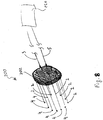
particular lesion 50 created using the bipolar electrosurgical system and method ofFigs. 4-7 is not well suited for performing other ablation procedures due to the resulting ellipsoid shape. Therefore, it is envisioned that the presently-described bipolar electrosurgical system may also be configured to create spherical lesions as shown inFig. 8 . - For example,
Fig. 8 shows anablation device 200 having six pairs of bipolar electrodes (e.g., the active and returnelectrodes 2, 4) arranged in a generally circular pattern. Those skilled in the art will appreciate that the number of electrodes in theablation device 200 depends on a number of factors (e.g., size of the lesion, power level, etc.). The electrodes are held by ahousing 202 which contains thecables 3, 5 providing an electrical connection to thegenerator 10. It is envisioned that thehousing 202 may have an adjustable circumference thereby allowing the lesion area to be ablated by the electrodes to be regulated according to a specific purpose. - The
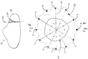
ablation device 200 allows for creation of alesion 64 which more closely approximates a circle by using a series of pairs of bipolar electrodes (e.g., the active and returnelectrodes 2, 4) arranged in a circular pattern as shown. As can be appreciated, thelesion 64 is better suited for covering a circular/spherical target area in need of ablation (e.g., a tumor 60).Lesion 64 is created by multiplexing the RF energy in different directions which involves switching the RF energy through each pair of the active and returnelectrodes arrows 62 representing the current flow. This would be accomplished by passing electrical energy sequentially through the active electrode(s) 2 while including only the corresponding return electrode(s) 4 in the circuit so that the current flows in one particular direction. It is envisioned amultiplexer 260 may be employed to control switching of the active and returnelectrodes multiplexer 260 may be configured to regulate the current in any fashion by switching on and off various pairs of active and return electrode pairs to createlesions 50. Moreover it is also contemplated thatmultiplexer 260 may be configured to change active and return electrode to reverse polarity and reverse the current therethrough thelesions 50 depending on particular purpose. - With respect to
Fig. 8 and as a result of multiplexing, each pair of the active and returnelectrodes lesion 64, which closely approximates a sperical lesion which has been conventionally created using monopolar devices. Those skilled in the art will appreciate thatFig. 9 shows only a cross section of thelesion 64 and that thelesion 64 has a depth equivalent to the exposed tips of the active and returnelectrodes
Claims (6)
- A bipolar electrosurgical system comprising:a plurality of pairs of an active (2) and a return (4) electrode each including thermally-conductive tubular members (11) with closed distal ends (12), the tubular members each including a respective active or return electrically conductive portion which is adapted to connect to an electrical energy source (10) connectable to reference potential, the active (2) and return (4) electrodes configured to penetrate tissue (6, 60) and create at least one generally elliptical lesion (50, 64) therebetween upon activation of electrical energy; anda multiplexer (266) disposed between the portions adapted to connect to the electrical energy source (10) and each pair of electrically conductive active and return portions, said multiplexer adapted to supply electrical energy to the active electrode (2) from the electrical energy source (10), to return the supplied electrical energy to the electrical energy source (10) from the penetrated tissue (6, 60) by the return electrode (4), and to selectively switch the electrical potential of each pair of active and return electrically conductive portions to create lesions (50, 54) of varying geometry, characterized in that as a result of multiplexing by the multiplexer, each pair of the active and return electrodes (2, 4) generates a lesion having an ellipsoid shape and a plurality of the ellipsoid shaped lesions having the same center overlap.
- A bipolar electrosurgical system of claim 1, further comprising:a current sensor (72) configured to measure current between each pair of active (2) and return (4) electrodes; anda voltage sensor (74) configured to measure voltage between each pair of active (2) and return (4) electrodes.
- A bipolar electrosurgical system of claim 2, further comprising:a microprocessor (80) in electrical communication with the current sensor (72) configured to calculate the impedance between the active electrode (2) and the return electrode (4) based on the measured current and measured voltage;a comparator (34) operatively associated with the electrical energy source (10) and configured to compare the calculated impedance to an activation range of impedance values; anda controller (2) operatively associated with the electrical energy source (10) and configured to automatically deactivate the electrical energy source (10) if the calculated impedance exceeds a deactivation threshold.
- A bipolar electrosurgical system of claim 3, wherein the deactivation threshold is 2000 Ohms.
- A bipolar electrosurgical system of claim 3 or 4, further comprising a filter for blocking energy from an output of the electrical energy source (10) from the impedance detection circuit, the filter being in electrical communication with the current sensor (72).
- A bipolar electrosurgical system of any one of the preceding claims, wherein at least each active electrode (2) of said at least one pair of active (2) and return (4) electrode further comprises:a first interior cavity extending from the closed distal end (12) of the tubular member (11) to a proximal end thereof;a first fluid conduit (26) sized to extend into the first interior cavity and adapted to be connected to a source of coolant (34) to supply coolant for cooling tissue contiguous to the first exposed portion;a temperature sensor (23) disposed within the first interior cavity configured to detect a temperature; anda regulator (32) operatively connected to the source of coolant (34) configured to adaptively provide coolant to the fluid conduit (26) according to the measured temperature.
Applications Claiming Priority (1)
| Application Number | Priority Date | Filing Date | Title |
|---|---|---|---|
| US11/239,999 US20070078454A1 (en) | 2005-09-30 | 2005-09-30 | System and method for creating lesions using bipolar electrodes |
Publications (2)
| Publication Number | Publication Date |
|---|---|
| EP1769763A1 EP1769763A1 (en) | 2007-04-04 |
| EP1769763B1 true EP1769763B1 (en) | 2018-03-07 |
Family
ID=37591822
Family Applications (1)
| Application Number | Title | Priority Date | Filing Date |
|---|---|---|---|
| EP05025423.4A Revoked EP1769763B1 (en) | 2005-09-30 | 2005-11-22 | System for creating lesions using bipolar electrodes |
Country Status (4)
| Country | Link |
|---|---|
| US (1) | US20070078454A1 (en) |
| EP (1) | EP1769763B1 (en) |
| AU (1) | AU2005256093A1 (en) |
| CA (1) | CA2529586A1 (en) |
Families Citing this family (36)
| Publication number | Priority date | Publication date | Assignee | Title |
|---|---|---|---|---|
| US7282049B2 (en) * | 2004-10-08 | 2007-10-16 | Sherwood Services Ag | Electrosurgical system employing multiple electrodes and method thereof |
| US7553309B2 (en) * | 2004-10-08 | 2009-06-30 | Covidien Ag | Electrosurgical system employing multiple electrodes and method thereof |
| US20070078454A1 (en) | 2005-09-30 | 2007-04-05 | Mcpherson James W | System and method for creating lesions using bipolar electrodes |
| US20070078502A1 (en) * | 2005-10-05 | 2007-04-05 | Thermage, Inc. | Method and apparatus for estimating a local impedance factor |
| US8702691B2 (en) * | 2005-10-19 | 2014-04-22 | Thermage, Inc. | Treatment apparatus and methods for delivering energy at multiple selectable depths in tissue |
| US7763018B2 (en) * | 2006-07-28 | 2010-07-27 | Covidien Ag | Cool-tip thermocouple including two-piece hub |
| US8211099B2 (en) | 2007-01-31 | 2012-07-03 | Tyco Healthcare Group Lp | Thermal feedback systems and methods of using the same |
| US9486269B2 (en) * | 2007-06-22 | 2016-11-08 | Covidien Lp | Electrosurgical systems and cartridges for use therewith |
| US8216218B2 (en) * | 2007-07-10 | 2012-07-10 | Thermage, Inc. | Treatment apparatus and methods for delivering high frequency energy across large tissue areas |
| US8181995B2 (en) * | 2007-09-07 | 2012-05-22 | Tyco Healthcare Group Lp | Cool tip junction |
| US8292880B2 (en) | 2007-11-27 | 2012-10-23 | Vivant Medical, Inc. | Targeted cooling of deployable microwave antenna |
| US8682425B2 (en) * | 2008-01-30 | 2014-03-25 | Miridia Technology Inc. | Electroacupuncture system |
| US8965536B2 (en) * | 2008-03-03 | 2015-02-24 | Covidien Lp | Intracooled percutaneous microwave ablation probe |
| US8608739B2 (en) | 2008-07-22 | 2013-12-17 | Covidien Lp | Electrosurgical devices, systems and methods of using the same |
| US20100130976A1 (en) * | 2008-11-21 | 2010-05-27 | Smith & Nephew Inc. | Reducing cross-talk effects in an rf electrosurgical device |
| US20100256735A1 (en) * | 2009-04-03 | 2010-10-07 | Board Of Regents, The University Of Texas System | Intraluminal stent with seam |
| US8672938B2 (en) | 2009-07-23 | 2014-03-18 | Covidien Lp | Active cooling system and apparatus for controlling temperature of a fluid used during treatment of biological tissue |
| US8568404B2 (en) | 2010-02-19 | 2013-10-29 | Covidien Lp | Bipolar electrode probe for ablation monitoring |
| US9579150B2 (en) | 2011-04-08 | 2017-02-28 | Covidien Lp | Microwave ablation instrument with interchangeable antenna probe |
| KR101248959B1 (en) * | 2011-05-12 | 2013-04-01 | 신경민 | Electrode device having flexible tube for high frequency thermotherapy |
| US9358065B2 (en) | 2011-06-23 | 2016-06-07 | Covidien Lp | Shaped electrode bipolar resection apparatus, system and methods of use |
| US10076383B2 (en) | 2012-01-25 | 2018-09-18 | Covidien Lp | Electrosurgical device having a multiplexer |
| CA2924050C (en) * | 2012-09-20 | 2021-11-02 | Checkpoint Surgical, Llc | Stimulation device adapter |
| KR20190062419A (en) | 2016-10-04 | 2019-06-05 | 아벤트, 인크. | The cooled RF probe |
| US12137961B2 (en) | 2019-03-25 | 2024-11-12 | Covidien Lp | Electrosurgical pencil with a protective guard |
| EP4065005A4 (en) | 2019-11-27 | 2023-12-27 | North Carolina State University | METHODS FOR REGULATING TREATMENT VOLUMES, THERMAL GRADIENTS, MUSCLE STIMULATION AND IMMUNE RESPONSES IN PULSED ELECTRIC FIELD TREATMENTS |
| US11779394B2 (en) | 2020-01-30 | 2023-10-10 | Covidien Lp | Single-sided low profile end effector for bipolar pencil |
| US11596467B2 (en) | 2020-02-04 | 2023-03-07 | Covidien Lp | Articulating tip for bipolar pencil |
| US11944367B2 (en) | 2020-02-05 | 2024-04-02 | Covidien Lp | Electrosurgical device for cutting tissue |
| US11864815B2 (en) | 2020-02-06 | 2024-01-09 | Covidien Lp | Electrosurgical device for cutting tissue |
| US11864817B2 (en) | 2020-02-13 | 2024-01-09 | Covidien Lp | Low profile single pole tip for bipolar pencil |
| US11712285B2 (en) | 2020-04-23 | 2023-08-01 | Covidien Lp | Dual-threaded tensioning mechanism for bipolar pencil |
| US11648046B2 (en) | 2020-04-29 | 2023-05-16 | Covidien Lp | Electrosurgical instrument for cutting tissue |
| US11684413B2 (en) | 2020-05-22 | 2023-06-27 | Covidien Lp | Smoke mitigation assembly for bipolar pencil |
| US11864818B2 (en) | 2020-06-12 | 2024-01-09 | Covidien Lp | End effector assembly for bipolar pencil |
| US20220000543A1 (en) * | 2020-07-06 | 2022-01-06 | Biosense Webster (Israel) Ltd. | Bipolar tissue ablation in accordance with a predefined periodic set of time slots |
Citations (9)
| Publication number | Priority date | Publication date | Assignee | Title |
|---|---|---|---|---|
| US5334193A (en) | 1992-11-13 | 1994-08-02 | American Cardiac Ablation Co., Inc. | Fluid cooled ablation catheter |
| WO1996034571A1 (en) | 1995-05-04 | 1996-11-07 | Cosman Eric R | Cool-tip electrode thermosurgery system |
| WO1999022657A1 (en) | 1997-11-03 | 1999-05-14 | Rita Medical Systems, Inc. | Multiple antenna ablation apparatus and method |
| US6203541B1 (en) | 1999-04-23 | 2001-03-20 | Sherwood Services Ag | Automatic activation of electrosurgical generator bipolar output |
| US20020193851A1 (en) * | 2001-06-14 | 2002-12-19 | Silverman David E. | Energy treatment apparatus for treating gastrointestinal tract and method for using same |
| DE10224154A1 (en) | 2002-05-27 | 2003-12-18 | Celon Ag Medical Instruments | Application device for electrosurgical device for body tissue removal via of HF current has electrode subset selected from active electrode set in dependence on measured impedance of body tissue |
| US20040181216A1 (en) | 2003-03-13 | 2004-09-16 | Kelly Amy C. | Surface electrode multiple mode operation |
| FR2864439A1 (en) | 2003-12-30 | 2005-07-01 | Image Guided Therapy | Tumor treating device for use by surgeon, has generator applying voltage to each of active electrodes in manner independent from other electrodes and having sinusoidal voltage generation unit adjusting amplitude and phase of voltage |
| EP1769763A1 (en) | 2005-09-30 | 2007-04-04 | Sherwood Services AG | System for creating lesions using bipolar electrodes |
Family Cites Families (90)
| Publication number | Priority date | Publication date | Assignee | Title |
|---|---|---|---|---|
| US2031682A (en) * | 1932-11-18 | 1936-02-25 | Wappler Frederick Charles | Method and means for electrosurgical severance of adhesions |
| US4074718A (en) * | 1976-03-17 | 1978-02-21 | Valleylab, Inc. | Electrosurgical instrument |
| US4608977A (en) * | 1979-08-29 | 1986-09-02 | Brown Russell A | System using computed tomography as for selective body treatment |
| US4375220A (en) * | 1980-05-09 | 1983-03-01 | Matvias Fredrick M | Microwave applicator with cooling mechanism for intracavitary treatment of cancer |
| US4565200A (en) * | 1980-09-24 | 1986-01-21 | Cosman Eric R | Universal lesion and recording electrode system |
| JPS5957650A (en) * | 1982-09-27 | 1984-04-03 | 呉羽化学工業株式会社 | Probe for heating body cavity |
| US4576177A (en) * | 1983-02-18 | 1986-03-18 | Webster Wilton W Jr | Catheter for removing arteriosclerotic plaque |
| US4739759A (en) * | 1985-02-26 | 1988-04-26 | Concept, Inc. | Microprocessor controlled electrosurgical generator |
| FR2597744A1 (en) * | 1986-04-29 | 1987-10-30 | Boussignac Georges | CARDIO-VASCULAR CATHETER FOR LASER SHOOTING |
| JPH0511882Y2 (en) * | 1987-01-06 | 1993-03-25 | ||
| US4945912A (en) * | 1988-11-25 | 1990-08-07 | Sensor Electronics, Inc. | Catheter with radiofrequency heating applicator |
| US5225741A (en) * | 1989-03-10 | 1993-07-06 | Bruce Industries, Inc. | Electronic ballast and power controller |
| US5029588A (en) * | 1989-06-15 | 1991-07-09 | Cardiovascular Imaging Systems, Inc. | Laser catheter with imaging capability |
| US5233515A (en) * | 1990-06-08 | 1993-08-03 | Cosman Eric R | Real-time graphic display of heat lesioning parameters in a clinical lesion generator system |
| US5103804A (en) * | 1990-07-03 | 1992-04-14 | Boston Scientific Corporation | Expandable tip hemostatic probes and the like |
| US5417686A (en) * | 1990-07-10 | 1995-05-23 | The Texas A&M University System | Temperature control mechanisms for a micro heat pipe catheter |
| US5792146A (en) * | 1990-10-09 | 1998-08-11 | Cosman; Eric R. | Rectilinear linac phantom pointer system |
| US5662111A (en) * | 1991-01-28 | 1997-09-02 | Cosman; Eric R. | Process of stereotactic optical navigation |
| DE4122219A1 (en) * | 1991-07-04 | 1993-01-07 | Delma Elektro Med App | ELECTRO-SURGICAL TREATMENT INSTRUMENT |
| US5383917A (en) * | 1991-07-05 | 1995-01-24 | Jawahar M. Desai | Device and method for multi-phase radio-frequency ablation |
| US5323778A (en) * | 1991-11-05 | 1994-06-28 | Brigham & Women's Hospital | Method and apparatus for magnetic resonance imaging and heating tissues |
| US5230623A (en) * | 1991-12-10 | 1993-07-27 | Radionics, Inc. | Operating pointer with interactive computergraphics |
| US5330518A (en) * | 1992-03-06 | 1994-07-19 | Urologix, Inc. | Method for treating interstitial tissue associated with microwave thermal therapy |
| US5281213A (en) * | 1992-04-16 | 1994-01-25 | Implemed, Inc. | Catheter for ice mapping and ablation |
| WO1994002077A2 (en) * | 1992-07-15 | 1994-02-03 | Angelase, Inc. | Ablation catheter system |
| US5342357A (en) * | 1992-11-13 | 1994-08-30 | American Cardiac Ablation Co., Inc. | Fluid cooled electrosurgical cauterization system |
| AU5456494A (en) * | 1992-11-13 | 1994-06-08 | American Cardiac Ablation Co., Inc. | Fluid cooled electrosurgical probe |
| US5348554A (en) * | 1992-12-01 | 1994-09-20 | Cardiac Pathways Corporation | Catheter for RF ablation with cooled electrode |
| DE4240722C2 (en) * | 1992-12-03 | 1996-08-29 | Siemens Ag | Device for the treatment of pathological tissue |
| US5403311A (en) * | 1993-03-29 | 1995-04-04 | Boston Scientific Corporation | Electro-coagulation and ablation and other electrotherapeutic treatments of body tissue |
| US5395368A (en) * | 1993-05-20 | 1995-03-07 | Ellman; Alan G. | Multiple-wire electrosurgical electrodes |
| DE69434185T2 (en) * | 1993-06-10 | 2005-06-02 | Imran, Mir A., Los Altos Hills | URETHRAL DEVICE FOR ABLATION BY HIGH FREQUENCY |
| US5385148A (en) * | 1993-07-30 | 1995-01-31 | The Regents Of The University Of California | Cardiac imaging and ablation catheter |
| US5921982A (en) * | 1993-07-30 | 1999-07-13 | Lesh; Michael D. | Systems and methods for ablating body tissue |
| US5409000A (en) * | 1993-09-14 | 1995-04-25 | Cardiac Pathways Corporation | Endocardial mapping and ablation system utilizing separately controlled steerable ablation catheter with ultrasonic imaging capabilities and method |
| US5433739A (en) * | 1993-11-02 | 1995-07-18 | Sluijter; Menno E. | Method and apparatus for heating an intervertebral disc for relief of back pain |
| US5599345A (en) * | 1993-11-08 | 1997-02-04 | Zomed International, Inc. | RF treatment apparatus |
| US5536267A (en) * | 1993-11-08 | 1996-07-16 | Zomed International | Multiple electrode ablation apparatus |
| US6241725B1 (en) * | 1993-12-15 | 2001-06-05 | Sherwood Services Ag | High frequency thermal ablation of cancerous tumors and functional targets with image data assistance |
| US6530922B2 (en) * | 1993-12-15 | 2003-03-11 | Sherwood Services Ag | Cluster ablation electrode system |
| US5462521A (en) * | 1993-12-21 | 1995-10-31 | Angeion Corporation | Fluid cooled and perfused tip for a catheter |
| EP2314244A1 (en) * | 1994-12-13 | 2011-04-27 | Torben Lorentzen | An electrosurgical instrument for tissue ablation, an apparatus, and a method for providing a lesion in damaged and diseased tissue from a mammal |
| US5897553A (en) * | 1995-11-02 | 1999-04-27 | Medtronic, Inc. | Ball point fluid-assisted electrocautery device |
| US6106524A (en) * | 1995-03-03 | 2000-08-22 | Neothermia Corporation | Methods and apparatus for therapeutic cauterization of predetermined volumes of biological tissue |
| US5647871A (en) * | 1995-03-10 | 1997-07-15 | Microsurge, Inc. | Electrosurgery with cooled electrodes |
| US5868740A (en) * | 1995-03-24 | 1999-02-09 | Board Of Regents-Univ Of Nebraska | Method for volumetric tissue ablation |
| US6602248B1 (en) * | 1995-06-07 | 2003-08-05 | Arthro Care Corp. | Methods for repairing damaged intervertebral discs |
| US6053912A (en) * | 1995-05-01 | 2000-04-25 | Ep Techonologies, Inc. | Systems and methods for sensing sub-surface temperatures in body tissue during ablation with actively cooled electrodes |
| US6575969B1 (en) * | 1995-05-04 | 2003-06-10 | Sherwood Services Ag | Cool-tip radiofrequency thermosurgery electrode system for tumor ablation |
| US7179255B2 (en) * | 1995-06-07 | 2007-02-20 | Arthrocare Corporation | Methods for targeted electrosurgery on contained herniated discs |
| US6059780A (en) * | 1995-08-15 | 2000-05-09 | Rita Medical Systems, Inc. | Multiple antenna ablation apparatus and method with cooling element |
| US5735847A (en) * | 1995-08-15 | 1998-04-07 | Zomed International, Inc. | Multiple antenna ablation apparatus and method with cooling element |
| US6246912B1 (en) * | 1996-06-27 | 2001-06-12 | Sherwood Services Ag | Modulated high frequency tissue modification |
| IL119545A (en) * | 1996-11-01 | 2002-11-10 | Philips Medical Systems Techno | Method and device for precise invasive procedures |
| US5775338A (en) * | 1997-01-10 | 1998-07-07 | Scimed Life Systems, Inc. | Heated perfusion balloon for reduction of restenosis |
| US7218958B2 (en) * | 2004-02-23 | 2007-05-15 | St. Jude Medical, Atrial Fibrillation Division, Inc. | Electrophysiology/ablation catheter having second passage |
| US6287305B1 (en) * | 1997-12-23 | 2001-09-11 | Team Medical, L.L.C. | Electrosurgical instrument |
| US6080149A (en) * | 1998-01-09 | 2000-06-27 | Radiotherapeutics, Corporation | Method and apparatus for monitoring solid tissue heating |
| US6537272B2 (en) * | 1998-07-07 | 2003-03-25 | Medtronic, Inc. | Apparatus and method for creating, maintaining, and controlling a virtual electrode used for the ablation of tissue |
| US6212433B1 (en) * | 1998-07-28 | 2001-04-03 | Radiotherapeutics Corporation | Method for treating tumors near the surface of an organ |
| US6061551A (en) * | 1998-10-21 | 2000-05-09 | Parkervision, Inc. | Method and system for down-converting electromagnetic signals |
| ATE253957T1 (en) * | 1999-05-11 | 2003-11-15 | Exogen Inc | DEVICE FOR ULTRASONIC TREATMENT OF REFLEXSYMPATHIC DYSTROPHY |
| US7235073B2 (en) * | 2000-07-06 | 2007-06-26 | Ethicon Endo-Surgery, Inc. | Cooled electrosurgical forceps |
| US7422586B2 (en) * | 2001-02-28 | 2008-09-09 | Angiodynamics, Inc. | Tissue surface treatment apparatus and method |
| US7008421B2 (en) * | 2002-08-21 | 2006-03-07 | Resect Medical, Inc. | Apparatus and method for tissue resection |
| AU2002250170B2 (en) * | 2001-02-28 | 2006-08-10 | Rex Medical, L.P. | Apparatus for Delivering Ablation Fluid to Treat Lesions |
| US6685729B2 (en) * | 2001-06-29 | 2004-02-03 | George Gonzalez | Process for testing and treating aberrant sensory afferents and motors efferents |
| AU2002362310A1 (en) * | 2001-09-14 | 2003-04-01 | Arthrocare Corporation | Methods and apparatus for treating intervertebral discs |
| AU2002327779B2 (en) * | 2001-09-28 | 2008-06-26 | Angiodynamics, Inc. | Impedance controlled tissue ablation apparatus and method |
| US6827715B2 (en) * | 2002-01-25 | 2004-12-07 | Medtronic, Inc. | System and method of performing an electrosurgical procedure |
| US7367974B2 (en) * | 2004-09-20 | 2008-05-06 | Wisconsin Alumni Research Foundation | Electrode array for tissue ablation |
| US7220260B2 (en) * | 2002-06-27 | 2007-05-22 | Gyrus Medical Limited | Electrosurgical system |
| US7341586B2 (en) * | 2002-08-21 | 2008-03-11 | Resect Medical, Inc. | Thermal coagulation of tissue during tissue resection |
| US7186222B1 (en) * | 2002-09-10 | 2007-03-06 | Radiant Medical, Inc. | Vascular introducer with temperature monitoring probe and systems for endovascular temperature control |
| US7150749B2 (en) * | 2003-06-13 | 2006-12-19 | Sherwood Services Ag | Vessel sealer and divider having elongated knife stroke and safety cutting mechanism |
| US7156846B2 (en) | 2003-06-13 | 2007-01-02 | Sherwood Services Ag | Vessel sealer and divider for use with small trocars and cannulas |
| US7235070B2 (en) * | 2003-07-02 | 2007-06-26 | St. Jude Medical, Atrial Fibrillation Division, Inc. | Ablation fluid manifold for ablation catheter |
| US7207989B2 (en) * | 2003-10-27 | 2007-04-24 | Biosense Webster, Inc. | Method for ablating with needle electrode |
| DE502004009815D1 (en) * | 2003-10-29 | 2009-09-10 | Celon Ag Medical Instruments | Medical device for the electrotomy |
| US7811283B2 (en) * | 2003-11-19 | 2010-10-12 | Covidien Ag | Open vessel sealing instrument with hourglass cutting mechanism and over-ratchet safety |
| US7252667B2 (en) * | 2003-11-19 | 2007-08-07 | Sherwood Services Ag | Open vessel sealing instrument with cutting mechanism and distal lockout |
| US7131970B2 (en) * | 2003-11-19 | 2006-11-07 | Sherwood Services Ag | Open vessel sealing instrument with cutting mechanism |
| US7156842B2 (en) * | 2003-11-20 | 2007-01-02 | Sherwood Services Ag | Electrosurgical pencil with improved controls |
| US7238184B2 (en) * | 2004-03-15 | 2007-07-03 | Boston Scientific Scimed, Inc. | Ablation probe with peltier effect thermal control |
| US7367975B2 (en) * | 2004-06-21 | 2008-05-06 | Cierra, Inc. | Energy based devices and methods for treatment of anatomic tissue defects |
| US7553309B2 (en) * | 2004-10-08 | 2009-06-30 | Covidien Ag | Electrosurgical system employing multiple electrodes and method thereof |
| US7776035B2 (en) * | 2004-10-08 | 2010-08-17 | Covidien Ag | Cool-tip combined electrode introducer |
| US7282049B2 (en) * | 2004-10-08 | 2007-10-16 | Sherwood Services Ag | Electrosurgical system employing multiple electrodes and method thereof |
| US7763018B2 (en) * | 2006-07-28 | 2010-07-27 | Covidien Ag | Cool-tip thermocouple including two-piece hub |
| US8211099B2 (en) * | 2007-01-31 | 2012-07-03 | Tyco Healthcare Group Lp | Thermal feedback systems and methods of using the same |
-
2005
- 2005-09-30 US US11/239,999 patent/US20070078454A1/en not_active Abandoned
- 2005-11-22 EP EP05025423.4A patent/EP1769763B1/en not_active Revoked
- 2005-12-09 CA CA002529586A patent/CA2529586A1/en not_active Abandoned
- 2005-12-14 AU AU2005256093A patent/AU2005256093A1/en not_active Abandoned
Patent Citations (10)
| Publication number | Priority date | Publication date | Assignee | Title |
|---|---|---|---|---|
| US5334193A (en) | 1992-11-13 | 1994-08-02 | American Cardiac Ablation Co., Inc. | Fluid cooled ablation catheter |
| WO1996034571A1 (en) | 1995-05-04 | 1996-11-07 | Cosman Eric R | Cool-tip electrode thermosurgery system |
| US6506189B1 (en) | 1995-05-04 | 2003-01-14 | Sherwood Services Ag | Cool-tip electrode thermosurgery system |
| WO1999022657A1 (en) | 1997-11-03 | 1999-05-14 | Rita Medical Systems, Inc. | Multiple antenna ablation apparatus and method |
| US6203541B1 (en) | 1999-04-23 | 2001-03-20 | Sherwood Services Ag | Automatic activation of electrosurgical generator bipolar output |
| US20020193851A1 (en) * | 2001-06-14 | 2002-12-19 | Silverman David E. | Energy treatment apparatus for treating gastrointestinal tract and method for using same |
| DE10224154A1 (en) | 2002-05-27 | 2003-12-18 | Celon Ag Medical Instruments | Application device for electrosurgical device for body tissue removal via of HF current has electrode subset selected from active electrode set in dependence on measured impedance of body tissue |
| US20040181216A1 (en) | 2003-03-13 | 2004-09-16 | Kelly Amy C. | Surface electrode multiple mode operation |
| FR2864439A1 (en) | 2003-12-30 | 2005-07-01 | Image Guided Therapy | Tumor treating device for use by surgeon, has generator applying voltage to each of active electrodes in manner independent from other electrodes and having sinusoidal voltage generation unit adjusting amplitude and phase of voltage |
| EP1769763A1 (en) | 2005-09-30 | 2007-04-04 | Sherwood Services AG | System for creating lesions using bipolar electrodes |
Non-Patent Citations (4)
| Title |
|---|
| "CelonLab Power", CELON AG MEDICAL INSTRUMENTS, pages 1 - 174 |
| "Radio Frequency Ablation System: Cool-tip RF", TYCRO HEALTHCARE, 2000, pages 1 - 8, XP055616432 |
| RITZ ET AL.: "Bipolar radiofrequency ablation of liver metastases during laparotomy. First clinical experiences with a new multipolar ablation concept", INTERNATIONAL JOURNAL OF COLORECTAL DISEASE, 5 May 2005 (2005-05-05), pages 25 - 32, XP019340275, DOI: 10.1007/s00384-005-0781-y |
| TACKE ET AL.: "Multipolar Radiofrequency Ablation: First Clinical Results", ROTO, March 2004 (2004-03-01), pages 324 - 329, XP008126125 |
Also Published As
| Publication number | Publication date |
|---|---|
| EP1769763A1 (en) | 2007-04-04 |
| US20070078454A1 (en) | 2007-04-05 |
| AU2005256093A1 (en) | 2007-04-19 |
| CA2529586A1 (en) | 2007-03-30 |
Similar Documents
| Publication | Publication Date | Title |
|---|---|---|
| EP1769763B1 (en) | System for creating lesions using bipolar electrodes | |
| US8702693B2 (en) | Apparatus and methods for supplying fluid to an electrophysiology apparatus | |
| AU2012200903B2 (en) | Bipolar electrosurgical system | |
| US7846158B2 (en) | Apparatus and method for electrode thermosurgery | |
| AU2012268833B2 (en) | Electrode irrigation using micro-jets | |
| EP2679190B1 (en) | Irrigated electrodes with enhanced heat conduction | |
| WO2017075032A1 (en) | Electrosurgical apparatus with temperature sensing and methods of use thereof | |
| US20200015879A1 (en) | System and Method for Independent or Simultaneous Control of Multiple Radiofrequency Probes During an Ablation Procedure | |
| AU2019277095B2 (en) | Varying the length of a temperature sensing element of a radiofrequency probe based on desired lesion size | |
| US20210169558A1 (en) | Fiber Optic Temperature Sensor for Cooled Radiofrequency Probe | |
| US20210169557A1 (en) | System and Method for Generating Lesions of a Certain Size by Controlling Energy Delivered and Pump Flow Rate | |
| US9622812B2 (en) | Electrosurgical cannulas, systems and methods | |
| EP1767165B1 (en) | Cooled ablation needle | |
| CA2521267A1 (en) | Cooled rf ablation needle |
Legal Events
| Date | Code | Title | Description |
|---|---|---|---|
| PUAI | Public reference made under article 153(3) epc to a published international application that has entered the european phase |
Free format text: ORIGINAL CODE: 0009012 |
|
| AK | Designated contracting states |
Kind code of ref document: A1 Designated state(s): AT BE BG CH CY CZ DE DK EE ES FI FR GB GR HU IE IS IT LI LT LU LV MC NL PL PT RO SE SI SK TR |
|
| AX | Request for extension of the european patent |
Extension state: AL BA HR MK YU |
|
| RAP1 | Party data changed (applicant data changed or rights of an application transferred) |
Owner name: COVIDIEN AG |
|
| 17P | Request for examination filed |
Effective date: 20071002 |
|
| 17Q | First examination report despatched |
Effective date: 20071107 |
|
| AKX | Designation fees paid |
Designated state(s): DE ES FR GB IE IT |
|
| GRAP | Despatch of communication of intention to grant a patent |
Free format text: ORIGINAL CODE: EPIDOSNIGR1 |
|
| RIC1 | Information provided on ipc code assigned before grant |
Ipc: A61B 18/14 20060101AFI20170905BHEP Ipc: A61B 18/12 20060101ALI20170905BHEP |
|
| INTG | Intention to grant announced |
Effective date: 20170919 |
|
| RIN1 | Information on inventor provided before grant (corrected) |
Inventor name: MCPHERSON, JAMES W. |
|
| GRAS | Grant fee paid |
Free format text: ORIGINAL CODE: EPIDOSNIGR3 |
|
| GRAA | (expected) grant |
Free format text: ORIGINAL CODE: 0009210 |
|
| AK | Designated contracting states |
Kind code of ref document: B1 Designated state(s): DE ES FR GB IE IT |
|
| REG | Reference to a national code |
Ref country code: GB Ref legal event code: FG4D |
|
| REG | Reference to a national code |
Ref country code: IE Ref legal event code: FG4D |
|
| REG | Reference to a national code |
Ref country code: DE Ref legal event code: R096 Ref document number: 602005053604 Country of ref document: DE |
|
| PG25 | Lapsed in a contracting state [announced via postgrant information from national office to epo] |
Ref country code: ES Free format text: LAPSE BECAUSE OF FAILURE TO SUBMIT A TRANSLATION OF THE DESCRIPTION OR TO PAY THE FEE WITHIN THE PRESCRIBED TIME-LIMIT Effective date: 20180307 |
|
| REG | Reference to a national code |
Ref country code: FR Ref legal event code: PLFP Year of fee payment: 14 |
|
| PG25 | Lapsed in a contracting state [announced via postgrant information from national office to epo] |
Ref country code: IT Free format text: LAPSE BECAUSE OF FAILURE TO SUBMIT A TRANSLATION OF THE DESCRIPTION OR TO PAY THE FEE WITHIN THE PRESCRIBED TIME-LIMIT Effective date: 20180307 |
|
| REG | Reference to a national code |
Ref country code: DE Ref legal event code: R026 Ref document number: 602005053604 Country of ref document: DE |
|
| PLBI | Opposition filed |
Free format text: ORIGINAL CODE: 0009260 |
|
| PLAX | Notice of opposition and request to file observation + time limit sent |
Free format text: ORIGINAL CODE: EPIDOSNOBS2 |
|
| 26 | Opposition filed |
Opponent name: OLYMPUS WINTER & IBE GMBH Effective date: 20181206 |
|
| PGFP | Annual fee paid to national office [announced via postgrant information from national office to epo] |
Ref country code: DE Payment date: 20181023 Year of fee payment: 14 |
|
| PGFP | Annual fee paid to national office [announced via postgrant information from national office to epo] |
Ref country code: FR Payment date: 20181024 Year of fee payment: 14 Ref country code: GB Payment date: 20181024 Year of fee payment: 14 |
|
| REG | Reference to a national code |
Ref country code: IE Ref legal event code: MM4A |
|
| RDAF | Communication despatched that patent is revoked |
Free format text: ORIGINAL CODE: EPIDOSNREV1 |
|
| REG | Reference to a national code |
Ref country code: DE Ref legal event code: R064 Ref document number: 602005053604 Country of ref document: DE Ref country code: DE Ref legal event code: R103 Ref document number: 602005053604 Country of ref document: DE |
|
| PG25 | Lapsed in a contracting state [announced via postgrant information from national office to epo] |
Ref country code: IE Free format text: LAPSE BECAUSE OF NON-PAYMENT OF DUE FEES Effective date: 20181122 |
|
| RDAG | Patent revoked |
Free format text: ORIGINAL CODE: 0009271 |
|
| STAA | Information on the status of an ep patent application or granted ep patent |
Free format text: STATUS: PATENT REVOKED |
|
| 27W | Patent revoked |
Effective date: 20190926 |
|
| GBPR | Gb: patent revoked under art. 102 of the ep convention designating the uk as contracting state |
Effective date: 20190926 |