EP1768492B1 - An apparatus for trussing a bird - Google Patents
An apparatus for trussing a bird Download PDFInfo
- Publication number
- EP1768492B1 EP1768492B1 EP05761564A EP05761564A EP1768492B1 EP 1768492 B1 EP1768492 B1 EP 1768492B1 EP 05761564 A EP05761564 A EP 05761564A EP 05761564 A EP05761564 A EP 05761564A EP 1768492 B1 EP1768492 B1 EP 1768492B1
- Authority
- EP
- European Patent Office
- Prior art keywords
- bird
- main body
- leg
- bar
- shackle
- Prior art date
- Legal status (The legal status is an assumption and is not a legal conclusion. Google has not performed a legal analysis and makes no representation as to the accuracy of the status listed.)
- Expired - Lifetime
Links
Images
Classifications
-
- A—HUMAN NECESSITIES
- A22—BUTCHERING; MEAT TREATMENT; PROCESSING POULTRY OR FISH
- A22C—PROCESSING MEAT, POULTRY, OR FISH
- A22C21/00—Processing poultry
- A22C21/0038—Trussing poultry
Definitions
- the present invention relates to an apparatus for trussing a chicken or some similar bird.
- chickens are trussed manually by staff who are generally able to truss two to three chickens a minute. It takes anything from ten to fourteen weeks to train a person up to the level of competence where they can truss two to three chickens a minute. Out of every ten staff who start on this course, only two or three stay any considerable length of time. Additionally, in order to truss the chickens the tendons in the chickens's legs need to be vigorously flexed to allow the shanks and drumsticks of the chicken to be subsequently folded inside the body cavity of the chicken. The shanks are the end pieces of the chicken's legs once the feet have been removed and the shanks are connected to the drumsticks which are connected to the thighbones in turn.
- the European Patent application EP 0 413 629 discloses a method and device for arranging legs of slaughtered poultry.
- the legs are bended against the body and fixed in the bended position using a tie.
- the device comprises at least one shaping station, including lifting means to lift the body after gripping the legs of the birds to fold the legs while lifting the body.
- Such an apparatus is complex and provides limited control of the process conducted.
- the present invention provides an apparatus for trussing a bird according claim 1.
- a bird leg shank insertion means is movably mounted on the main body to receive and urge a bird's leg shanks inside the bird's own body cavity wherein second drive means are operably engageable with the shank insertion means.
- a pressing means is movably mounted on the shackle means and the pressing means is movable relative to the shackle means wherein third drive means are operably engageable with the pressing means.
- compression means are movably mounted on the wishbone end of the main body and the keel end of the main body to engage the wishbone end and the keel end of the bird and to compress these ends together wherein fourth drive means are operably engageable with the compression means.
- the drive means comprises a number of actuators selected from a group consisting of cams, guide rails, pneumatic and electromagnetic actuators.
- the clamping means comprises an elongate clamping bar pivotally mounted on the main body.
- the elongate clamping bar protrudes from the keel end of the main body centrally above the platform.
- the elongate clamping bar has a bird clamping end and a drive means engaging end.
- the shank insertion means comprises a chute movably mounted on a shank insertion bar which is slidably mounted on the main body.
- the chute protrudes from the keel end of the main body and extends into a space above the platform and the clamping means.
- the shank insertion means comprises an associated shank-tucking member slidably movable along the chute.
- the shank-tucking member is normally located at the keel end of the chute and is operable between this normal position and a location along the chute toward the wishbone end of the chute by a shank tucking member drive means.
- the chute is an inverted u-shaped section having mutually opposing cutaway slots on opposite lateral side members of the u-shaped section.
- the chute is pivotally mounted on one end of the shank insertion bar.
- the other end of the shank insertion bar has drive-engaging means.
- the shank insertion bar has a biasing means normally biasing the chute into a retracted position out of the body cavity of the bird.
- the shackle means comprises an elongate bracket extending transverse the main plane of the main body at our about the bird keel end of the main body, the elongate bracket having a u-shaped recess on opposite ends of the elongate bracket for receiving the - legs of a bird.
- the pressing means comprises a lever carrying an elongate presser bar having a rigid roller on opposite ends of the presser bar.
- the leg engaging and supporting means comprises a pair of mirror image rod arrangements each having a substantially horizontal mounting rod pivotally mounted at or about a lateral edge of the bird wishbone end of the main body.
- an elongate member extends from the outer end of the mounting rod and has a plane of rotation substantially parallel to the main plane of the main body, a leg engaging rod being mounted at the end of the elongate member and extending toward the main body.
- a leg supporting rod is mounted on the elongate member adjacent the leg engaging rod and extending in a direction from the bird keel end to the bird wishbone end of the main body.
- the compression means comprises a pusher plate movably mounted on the main body intermediate the chute and the clamping bar and a breast lifting mechanism movably mounted on the bird wishbone end of the main body.
- the pusher plate is mounted on an elongate pusher plate bar which is slidably mounted on the main body.
- the end of the pusher plate bar distal from the pusher plate has means for engaging drive means.
- the pusher plate is inclined at a predetermined angle for optimising shank and leg insertion into the body cavity of the bird.
- the angle of the pusher plate is in the range of 20° to 40°.
- the pusher plate bar has a biasing means normally biasing the pusher plate towards the main body away from the keel of the bird.
- the breast lifting mechanism comprises a breast engaging plate mounted on a lever which is pivotally mounted on the bird wish bone end of the main body, the end of the lever, distal from the pivot having means for engaging a drive means.
- the platform is movable relative to the main body.
- the first drive means comprises a clamping guide operably engageable with the clamping means for moving the clamping means between a chicken clamping position and a chicken mounting and releasing position, a leg engaging and supporting means actuator for activating the leg engaging and supporting means between an inoperative position and a leg supporting position and between an inoperative position and a leg stretching position and a means for sealing and releasing the shackle means.
- the third drive means further comprises a pressing guide for operable engagement with the pressing means for moving the pressing means between a normally retracted inoperative mode and an operative fully forward mode for flexing a chickens tendons by bending their shanks forward.
- the fourth drive means comprises a breast-lifting mechanism guide for operable engagement with the breast-lifting mechanism for moving the mechanism between a normally lowered position into a raised position simultaneously with the action of a second cam surface moving the pusher plate forward to effect compression of the chicken body.
- the second drive means comprises a tucking member actuator for activating the tucking member of the shank insertion means and a first cam surface operably engageable with the shank insertion means to move it between a chicken loading position where the shank insertion means is located over the platform to be inside the body cavity of a chicken and a chicken unloading position where the shank insertion means is withdrawn out of the body cavity of the chicken.
- any other suitable type of actuator can also be used if desired and the actuator units described in this specification are only an example of the many actuators freely available to be used to activate the relevant moving parts of the trussing apparatus and the trussing carousel assembly.
- the elongate clamping bar extends substantially parallel to the longitudinal axis of the platform and main body.
- the drive means engaging end of the elongate clamping bar is a cam-engaging end.
- the drive means engaging end of the clamping bar is connected to a pneumatic cylinder.
- the cylinder allows the clamping bar to be adjusted to a range of different clamping positions to compensate for the various positions of the adjustable platform.
- the chicken damping end and the cam-engaging end of the clamping bar are on opposite sides of the pivot.
- the shank tucking member drive means is electromagnetic, pneumatic or mechanical.
- the shank tucking member drive means is a linear pneumatic cylinder.
- the drive-engaging means of the shank insertion bar is a wheel.
- the pressing means comprises a lever mechanism carrying an elongate pressing bar having a rigid roller on opposite ends of the bar, the bar being spaced apart from the bracket and having a longitudinal axis substantially parallel to the longitudinal axis of the bracket so that movement of the lever causes the rollers to rotate around the u-shaped recesses of the elongate bracket.
- the leg-supporting rod of the leg engaging and supporting means mitigates against rotation of the legs of the chickens during the knuckle-tightening phase and reduces the risk of breakage.
- a wheel is mounted on the pusher plate for engaging the drive means.
- the drive means for engaging the pusher plate wheel is a cam.
- a roller is mounted on the breast lifting mechanism for engaging the drive means.
- a trussing apparatus indicated generally by the reference numeral 1.
- the trussing apparatus 1 is referred to as a long shank trussing apparatus 1 and is used with birds which have there shanks retained on the ends of their legs.
- An alternative embodiment of trussing apparatus known as a short shank trussing apparatus is briefly described following the detailed description of the long shank trussing apparatus 1.
- the trussing apparatus 1 comprises a main body 2 having a platform 3 for supporting a chicken or other similar bird (not shown) breast bone up.
- the platform 3 has a chicken keel end 4 and a chicken wishbone end 5.
- An elongate clamping bar 7 is pivotally mounted on the main body 2 about pivot 9 and extends from behind the main body 2 there through and projects from the keel end of the main body 2 into the space above the platform 3 and into the body cavity of a chicken resting thereon (not shown) in use.
- the elongate clamping bar 7 has a clamping end 11 and a drive-engaging end 12 carrying a roller 14.
- the drive-engaging end 12 has a mounting bracket for receiving the driving rod of a pneumatic cylinder.
- a shank insertion arrangement indicated generally by the reference number 15 has a chute 17 pivotally mounted to an elongate shank insertion bar 19 which is slidably mounted in the main body 2.
- the longitudinal axis of the shank insertion bar 19 is substantially parallel to the main plane of the main body 2.
- the shank insertion bar 19 has a guide bar 20 which carries a biasing device such as a compression spring (not shown) between the rear end wall 22 of the main body 2 and a drive-engaging end 2-3 of the shank insertion bar 19 distal from the chute 17.
- This drive-engaging end 23 also carries a wheel 25.
- the chute 17 is an inverted u-shaped section 27 having mutually opposing cutaway slots 28 on opposite lateral side members 29 of the inverted u-shaped section 27.
- the chute 17 extends free end 31 first into the body cavity of a chicken through the keel end of the chicken.
- the chute 17 also has a tucking member (not shown) normally located about the pivotally mounted end 33 of the chute 17 which tucking member is housed within the confines of the u-shaped section 27.
- the tucking member is slidably movable from the pivotally mounted end 33 towards the free end 31 of the chute 17 by a pneumatic cylinder 34 having a longitudinal axis parallel to the longitudinal axis of the chute 17.
- a pair of shackles 35 is mounted on a mounting block 42 on top of the pivotally mounted end 33 of the chute 17.
- the shackles 35 are provided by an elongate bracket 36 extending transverse the longitudinal axis of the chute 17, the bracket 36 having a u-shaped recess 38 on opposite ends thereof.
- a lever 41 is pivotally mounted on the mounting block 42.
- the lever 41 has an elongate presser bar 45 mounted midway along the length of the lever 41 transverse of and substantially perpendicular to the levers longitudinal axis.
- the presser bar 45 has a rigid roller 46 on both of its opposite ends.
- the presser bar 45 is spaced apart from the shackle bracket 36 and the longitudinal axis of the shackle bracket 36 and the longitudinal axis of the presser bar 45 are substantially parallel.
- a free drive-engaging end 51 of the lever 41 carries a roller 52.
- a biasing device (not shown) is mounted intermediate the lever 41 and the mounting block 42 to return the lever 41 to the position shown in the drawing after the lever 41 is pivoted forward by a drive means (not shown) to flex the tendons of the chicken legs held in the shackle bracket 36.
- a leg engaging and supporting arrangement indicated generally by the reference numeral 61 comprises a pair of mirror image rod arrangements 62 each having a substantially horizontal mounting rod 63 pivotally mounted transverse the main plane of the main body 2 and extending laterally there from at or about the wishbone end of the main body 2.
- An elongate bar 65 is mounted on the mounting rod 63 substantially perpendicular to the longitudinal axis of the mounting rod 63 and the elongate bar 65 has a plane of rotation substantially parallel to the main plane of the main body 2.
- a leg-engaging rod 66 is mounted on the end of the elongate bar 65.
- a leg-supporting rod (not shown) is mounted on the end of the elongate bar 65 with a longitudinal axis substantially parallel to the main plane of the main body 2 and extends in the direction from the keel end to the wishbone end of the main body 2.
- Activation of each rod arrangement 62 is provided by two pneumatic cylinders 71 one of which is mounted between each lateral surface 73 of the main body 2 and both mounting rods 74, one of which is shown.
- a bird body compression arrangement indicated generally by the reference numeral 81 has a pusher plate 82 mounted on a pusher plate bar 83 which is slidably mounted in the main body 2 intermediate the shank insertion bar 19 and the clamping bar 7.
- the pusher plate bar 83 has a pusher plate guide rod 85 which carries a biasing means such as a compression spring, not shown, intermediate the rear end wall 22 of the main body 2 and the drive engaging end 87 of the pusher plate bar 83.
- the drive engaging end 87 of the pusher plate bar 83 has a wheel 88.
- the second component part of the compression arrangement 81 is the breast lifting mechanism 91 comprising a breast-lifting lever 92 pivotally mounted on the wishbone end of the main body 2.
- the lever 92 has a breast engaging plate 93 and a free end 94 of the lever 92 has a drive-engaging roller 95.
- a preferred carousel trussing assembly indicated generally by the reference numeral 101.
- a plurality of long shank trussing apparatuses 1 are mounted on a rotating table 102.
- the table 102 is rotated by a central drive shaft 104 powered by a motor and gearbox 201.
- a central cam 105 is fixed and has a first surface for engaging with the wheel 25 of the shank insertion bar 19.
- the same cam 105 has a second surface which is operably engageable with the wheel 88 of the pusher plate bar 83, see Figure 1 .
- a clamping bar circular guide rail is also mounted on a stationary component of the assembly 101 and it has two circumferential portions at different vertical heights for engaging with the roller 14 of the elongate clamping bar 7 to move the clamping bar 7 between a camping position and a non- clamping position. Additionally, a presser bar circular guide rail and a breast lifting circular guide rail are provided to engage the roller 52 of the presser bar 45 and the roller 94 of the breast lifting mechanism lever 92 respectively at appropriate positions during the rotation of the table 102.
- a circular shank flexing rail is provided in front of the shackle bracket 36 at the angular positions where the presser bar 45 is urged forward by its associated guide rail and at positions where the cylinders 71 are actuated.
- the shank-flexing rail is located in front of the shackle bracket 36 at these locations to prevent the shanks from being pressed out of the shackle bracket 36.
- a lighting system 202 is also located on the assembly 101 to act as an alarm to indicate to an operator that it is time for a break.
- the chicken trussing apparatus 1 is mounted on a rotating table 102 or on a linear conveyor system. It will also be appreciated that the chicken trussing apparatus 1 can be operated in a stationary position with suitable electric, pneumatic, mechanical or electromagnetic drive means causing the necessary staged motions of the moving parts of the apparatus 1 under a control means such as a microcontroller avoiding the need for a moving conveyor.
- Each apparatus 1 passes by an operator who loads a bird onto each apparatus 1 at the desired speed of rotation of the table 102.
- the table 102 has variable speeds so that the factory management can adjust the table speed to suit the level of experience of the personnel manning the table 102 at that particular time.
- the loading operative lifts the chicken by the two legs and positions the bird so as the clamping bar 7 and the chute 17 enters the bird cavity.
- a cam surface of the central cam 105 acts on the wheel 25 to push the shank insertion bar 19 into a forward bird engaging position.
- the operative also positions both of the bird's legs into the corresponding u-shaped recess 38 on the shackle bracket 36. They also push the bird far enough onto the trussing apparatus 1 until the tail of the bird reaches a target spot marked clearly on the clamping bar 7.
- a central cam 105 or a pneumatic cylinder forces the drive engaging end 12 of the clamping bar 7 upwards which rotates about pivot 9 thus moving the clamping end 11 downwards which causes the bird to be clamped between the clamping bar 7 and the platform 3.
- the platform 3 is spring mounted therefore it is capable of vertical movement in use compensating for differences in different thickness of back bones of birds. This difference in size is the case in different sizes of birds and also different breeds of chickens. The bird is now securely clamped on the trussing apparatus 1.
- the leg engaging and supporting arrangement 61 has two functions. Firstly, it is used to position the chicken's legs into the shackle bracket 36 correctly and secondly it is used to bend the chicken's legs forward until they are substantially over the wings.
- the legs that are in the shackle bracket 36 pass behind a stationary shackle guide rail.
- a signal activates the pneumatic cylinders 71 and the leg engaging and supporting mechanism 61 is rotated forward and the leg engaging rod 66 engages the chicken's legs trying to remove the legs from the shackle bracket 36.
- the leg supporting rod support the birds' thighs preventing them from dragging along the shackle guide rail which would cause them to twist and result in leg breakage.
- the leg engaging and supporting mechanism 61 is again activated by the pneumatic cylinders 71 to push the legs out of the shackle 35 and move them fully forward until they are bent right forward until they are almost touching the wings. At this point the leg engaging and supporting mechanism 61 moves backward to its resting position by activation of the pneumatic cylinders 71.
- the bird has now come out of the enclosed protective tunnel area and the two legs are exposed towards an operative who places an elastic band around the two shanks in a figure eight configuration.
- a loop from the elastic band is pulled forward and positioned over the breast of the bird at the wish bone end.
- the operative also manually tucks in the wings for visual presentation.
- the chute 17 is fully extended forward inside the bird and is held forward by use of a circular cam 105.
- the operatives known as the leg operatives, take a leg in each hand and move them back towards the chute 17. He carefully positions the shanks through the cut away slots 28 in each side of the chute 17 in front of the tucking member. At the same time he carefully positions the elastic band which is in a figure eight around the shanks over the point of the keel bone of the bird. The operatives' role is now finished.
- the table 102 continues to rotate the trussing apparatuses 1 enter a second protected tunnel area and a signal activates the pneumatic cylinder 34 and causes the tucking member to move forward and forces the shanks to bend forward down the inside of the chute 17. They are now positioned in a shape ready to be directed down the chute 17 into the bird cavity.
- the pusher plate 82 starts to move forward by actuation of the central cam 105 on wheel 88 and simultaneously the breast support plate 93 starts to move upwards by use of an external guiding cam acting on the roller 95.
- the pusher plate 82 continues to move forward and is strategically designed so as it just rides over the top of the shanks which holds the shanks down, but also causes enough aggression so as to push the shanks and legs forward towards the cavity of the bird.
- Both the pusher plate 82 and the breast engaging plate 93 remain in this position and hold the bird effectively exerting pressure towards each other with the bird held in the middle. At this stage the surface of cam 105 acting on wheel 25 allows the chute 17 to move backwards out of the bird.
- the pusher plate 82 and the breast engaging plate 93 both move back to their resting positions as a result of disengagement with their respective cam surfaces and the bird is held together by the tension of the elastic band.
- the trussing apparatuses now move out of the second protected tunnel.
- the pressure exerted on the clamping bar 7 is relaxed as a result of disengagement of the wheel 14 from the its associated cam surface allowing the bird to be manually or automatically removed leaving the trussing apparatus 1 empty and available for reloading as it passes in front of the loading operative and ready to commence another cycle.
- each operative is exposed to strenuous repetitive strain injury, RSI.
- the strenuous jobs which are the bending of shanks and bending of legs and the insertion of shanks into the body cavity are removed from the operator immediately reducing the effects of RSI.
- the assembly has a three coloured stacked light system, which changes colour at an interval, deemed suitable by the health and safety team of the factory going to use the machine. This is fully adjustable from 1 min to 24 hours, although 30 mins appears an acceptable time frame. This if properly managed should create a management tool to minimise RSI.
- a short shank trussing apparatus In a second embodiment of trussing apparatus, referred to as a short shank trussing apparatus, the identical components as used and described above in relation to the long shank trussing apparatus 1 are used apart form the components required to flex the shanks and insert them into the body cavity of the bird.
- the components which are omitted from the short shank trussing apparatus are the chute 17, the lever 41, the presser bar 45, the rollers 46, the shank tucking member and the pneumatic cylinder 34. Additionally, there is no requirement for the components forming part of the compression arrangement 81.
- the second embodiment is referred to as the short shank trussing apparatus because the birds' shanks are removed from their legs before trussing begins.
- a saw is mounted on the assembly and cuts the birds' shanks off their legs as a first stage of the trussing operation.
- the saw may be mounted on the assembly at or about the location where the shackle guard rail first passes in front of the shackle to clamp the birds' legs therein.
- the saw may be mounted on an internal portion of a guard and is optionally an electrically powered saw.
Landscapes
- Life Sciences & Earth Sciences (AREA)
- Engineering & Computer Science (AREA)
- Wood Science & Technology (AREA)
- Zoology (AREA)
- Food Science & Technology (AREA)
- Processing Of Meat And Fish (AREA)
- Basic Packing Technique (AREA)
- Orthopedics, Nursing, And Contraception (AREA)
- Catching Or Destruction (AREA)
- Aerials With Secondary Devices (AREA)
- Meat, Egg Or Seafood Products (AREA)
Abstract
Description
- The present invention relates to an apparatus for trussing a chicken or some similar bird.
- Traditionally, chickens are trussed manually by staff who are generally able to truss two to three chickens a minute. It takes anything from ten to fourteen weeks to train a person up to the level of competence where they can truss two to three chickens a minute. Out of every ten staff who start on this course, only two or three stay any considerable length of time. Additionally, in order to truss the chickens the tendons in the chickens's legs need to be vigorously flexed to allow the shanks and drumsticks of the chicken to be subsequently folded inside the body cavity of the chicken. The shanks are the end pieces of the chicken's legs once the feet have been removed and the shanks are connected to the drumsticks which are connected to the thighbones in turn.
- This vigorous flexing of the chicken's legs can cause repetitive strain injury in the operative's joints, which is uncomfortable for the employee and can be costly to the employer.
- The European Patent application
EP 0 413 629 discloses a method and device for arranging legs of slaughtered poultry. The legs are bended against the body and fixed in the bended position using a tie. The device comprises at least one shaping station, including lifting means to lift the body after gripping the legs of the birds to fold the legs while lifting the body. Such an apparatus is complex and provides limited control of the process conducted. - It is an object of the present invention to overcome the above outlined problems.
- Accordingly, the present invention provides an apparatus for trussing a bird according claim 1.
- Ideally, a bird leg shank insertion means is movably mounted on the main body to receive and urge a bird's leg shanks inside the bird's own body cavity wherein second drive means are operably engageable with the shank insertion means.
- Preferably, a pressing means is movably mounted on the shackle means and the pressing means is movable relative to the shackle means wherein third drive means are operably engageable with the pressing means.
- Ideally, compression means are movably mounted on the wishbone end of the main body and the keel end of the main body to engage the wishbone end and the keel end of the bird and to compress these ends together wherein fourth drive means are operably engageable with the compression means.
- Preferably, the drive means comprises a number of actuators selected from a group consisting of cams, guide rails, pneumatic and electromagnetic actuators.
- Ideally, the clamping means comprises an elongate clamping bar pivotally mounted on the main body.
- Preferably, the elongate clamping bar protrudes from the keel end of the main body centrally above the platform.
- Ideally, the elongate clamping bar has a bird clamping end and a drive means engaging end.
- Preferably, the shank insertion means comprises a chute movably mounted on a shank insertion bar which is slidably mounted on the main body.
- Ideally, the chute protrudes from the keel end of the main body and extends into a space above the platform and the clamping means.
- Preferably, the shank insertion means comprises an associated shank-tucking member slidably movable along the chute.
- Ideally, the shank-tucking member is normally located at the keel end of the chute and is operable between this normal position and a location along the chute toward the wishbone end of the chute by a shank tucking member drive means.
- Preferably, the chute is an inverted u-shaped section having mutually opposing cutaway slots on opposite lateral side members of the u-shaped section.
- Ideally, the chute is pivotally mounted on one end of the shank insertion bar.
- Preferably, the other end of the shank insertion bar has drive-engaging means.
- Ideally, the shank insertion bar has a biasing means normally biasing the chute into a retracted position out of the body cavity of the bird.
- Preferably, the shackle means comprises an elongate bracket extending transverse the main plane of the main body at our about the bird keel end of the main body, the elongate bracket having a u-shaped recess on opposite ends of the elongate bracket for receiving the - legs of a bird.
- Ideally, the pressing means comprises a lever carrying an elongate presser bar having a rigid roller on opposite ends of the presser bar.
- Preferably, the leg engaging and supporting means comprises a pair of mirror image rod arrangements each having a substantially horizontal mounting rod pivotally mounted at or about a lateral edge of the bird wishbone end of the main body.
- Ideally, an elongate member extends from the outer end of the mounting rod and has a plane of rotation substantially parallel to the main plane of the main body, a leg engaging rod being mounted at the end of the elongate member and extending toward the main body.
- Preferably, a leg supporting rod is mounted on the elongate member adjacent the leg engaging rod and extending in a direction from the bird keel end to the bird wishbone end of the main body.
- Ideally, the compression means comprises a pusher plate movably mounted on the main body intermediate the chute and the clamping bar and a breast lifting mechanism movably mounted on the bird wishbone end of the main body.
- Preferably, the pusher plate is mounted on an elongate pusher plate bar which is slidably mounted on the main body.
- Ideally, the end of the pusher plate bar distal from the pusher plate has means for engaging drive means.
- Preferably, the pusher plate is inclined at a predetermined angle for optimising shank and leg insertion into the body cavity of the bird.
- Ideally, the angle of the pusher plate is in the range of 20° to 40°.
- Preferably, the pusher plate bar has a biasing means normally biasing the pusher plate towards the main body away from the keel of the bird.
- Ideally, the breast lifting mechanism comprises a breast engaging plate mounted on a lever which is pivotally mounted on the bird wish bone end of the main body, the end of the lever, distal from the pivot having means for engaging a drive means.
- Preferably, the platform is movable relative to the main body.
- Ideally, the first drive means comprises a clamping guide operably engageable with the clamping means for moving the clamping means between a chicken clamping position and a chicken mounting and releasing position, a leg engaging and supporting means actuator for activating the leg engaging and supporting means between an inoperative position and a leg supporting position and between an inoperative position and a leg stretching position and a means for sealing and releasing the shackle means.
- Preferably, the third drive means further comprises a pressing guide for operable engagement with the pressing means for moving the pressing means between a normally retracted inoperative mode and an operative fully forward mode for flexing a chickens tendons by bending their shanks forward. Ideally, the fourth drive means comprises a breast-lifting mechanism guide for operable engagement with the breast-lifting mechanism for moving the mechanism between a normally lowered position into a raised position simultaneously with the action of a second cam surface moving the pusher plate forward to effect compression of the chicken body. Preferably, the second drive means comprises a tucking member actuator for activating the tucking member of the shank insertion means and a first cam surface operably engageable with the shank insertion means to move it between a chicken loading position where the shank insertion means is located over the platform to be inside the body cavity of a chicken and a chicken unloading position where the shank insertion means is withdrawn out of the body cavity of the chicken.
- It will also be appreciated that any other suitable type of actuator can also be used if desired and the actuator units described in this specification are only an example of the many actuators freely available to be used to activate the relevant moving parts of the trussing apparatus and the trussing carousel assembly.
- Preferably, the elongate clamping bar extends substantially parallel to the longitudinal axis of the platform and main body.
- Preferably, the drive means engaging end of the elongate clamping bar is a cam-engaging end.
- Alternatively, the drive means engaging end of the clamping bar is connected to a pneumatic cylinder. The cylinder allows the clamping bar to be adjusted to a range of different clamping positions to compensate for the various positions of the adjustable platform.
- Ideally, the chicken damping end and the cam-engaging end of the clamping bar are on opposite sides of the pivot.
- Ideally, the shank tucking member drive means is electromagnetic, pneumatic or mechanical.
- Preferably, the shank tucking member drive means is a linear pneumatic cylinder.
- Preferably, the drive-engaging means of the shank insertion bar is a wheel.
- Preferably, the pressing means comprises a lever mechanism carrying an elongate pressing bar having a rigid roller on opposite ends of the bar, the bar being spaced apart from the bracket and having a longitudinal axis substantially parallel to the longitudinal axis of the bracket so that movement of the lever causes the rollers to rotate around the u-shaped recesses of the elongate bracket.
- Ideally, the leg-supporting rod of the leg engaging and supporting means mitigates against rotation of the legs of the chickens during the knuckle-tightening phase and reduces the risk of breakage.
- Preferably, a wheel is mounted on the pusher plate for engaging the drive means.
- Ideally, the drive means for engaging the pusher plate wheel is a cam.
- Preferably, a roller is mounted on the breast lifting mechanism for engaging the drive means.
- In another aspect of the invention, there is provided a carousel trussing assembly according claim to 34.
- The invention will now be described with reference to the accompanying drawings which show by way of example only one embodiment of trussing apparatus and one carousel trussing assembly comprising a plurality of trussing apparatuses according to the invention.
-
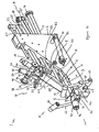
Fig. 1 is a perspective view of a trussing apparatus in accordance with the invention; -
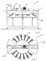
Fig. 2 is a side elevational view of a carousel trussing assembly; and -
Fig. 3 is a top plan view of the carousel trussing assembly ofFig. 2 . - Referring to
Fig. 1 there is shown a trussing apparatus indicated generally by the reference numeral 1. The trussing apparatus 1 is referred to as a long shank trussing apparatus 1 and is used with birds which have there shanks retained on the ends of their legs. An alternative embodiment of trussing apparatus known as a short shank trussing apparatus is briefly described following the detailed description of the long shank trussing apparatus 1. The trussing apparatus 1 comprises a main body 2 having aplatform 3 for supporting a chicken or other similar bird (not shown) breast bone up. Theplatform 3 has a chicken keel end 4 and achicken wishbone end 5. An elongate clampingbar 7 is pivotally mounted on the main body 2 aboutpivot 9 and extends from behind the main body 2 there through and projects from the keel end of the main body 2 into the space above theplatform 3 and into the body cavity of a chicken resting thereon (not shown) in use. Theelongate clamping bar 7 has a clamping end 11 and a drive-engagingend 12 carrying aroller 14. Alternatively, the drive-engagingend 12 has a mounting bracket for receiving the driving rod of a pneumatic cylinder. - A shank insertion arrangement indicated generally by the
reference number 15 has achute 17 pivotally mounted to an elongateshank insertion bar 19 which is slidably mounted in the main body 2. The longitudinal axis of theshank insertion bar 19 is substantially parallel to the main plane of the main body 2. - The
shank insertion bar 19 has aguide bar 20 which carries a biasing device such as a compression spring (not shown) between the rear end wall 22 of the main body 2 and a drive-engaging end 2-3 of theshank insertion bar 19 distal from thechute 17. This drive-engagingend 23 also carries awheel 25. - The
chute 17 is an invertedu-shaped section 27 having mutually opposingcutaway slots 28 on oppositelateral side members 29 of the invertedu-shaped section 27. - The
chute 17 extendsfree end 31 first into the body cavity of a chicken through the keel end of the chicken. Thechute 17 also has a tucking member (not shown) normally located about the pivotally mountedend 33 of thechute 17 which tucking member is housed within the confines of theu-shaped section 27. The tucking member is slidably movable from the pivotally mountedend 33 towards thefree end 31 of thechute 17 by apneumatic cylinder 34 having a longitudinal axis parallel to the longitudinal axis of thechute 17. - A pair of
shackles 35 is mounted on a mountingblock 42 on top of the pivotally mountedend 33 of thechute 17. Theshackles 35 are provided by anelongate bracket 36 extending transverse the longitudinal axis of thechute 17, thebracket 36 having au-shaped recess 38 on opposite ends thereof. Alever 41 is pivotally mounted on the mountingblock 42. - The
lever 41 has an elongate presser bar 45 mounted midway along the length of thelever 41 transverse of and substantially perpendicular to the levers longitudinal axis. The presser bar 45 has arigid roller 46 on both of its opposite ends. The presser bar 45 is spaced apart from theshackle bracket 36 and the longitudinal axis of theshackle bracket 36 and the longitudinal axis of the presser bar 45 are substantially parallel. A free drive-engagingend 51 of thelever 41 carries aroller 52. A biasing device (not shown) is mounted intermediate thelever 41 and the mountingblock 42 to return thelever 41 to the position shown in the drawing after thelever 41 is pivoted forward by a drive means (not shown) to flex the tendons of the chicken legs held in theshackle bracket 36. - A leg engaging and supporting arrangement indicated generally by the
reference numeral 61 comprises a pair of mirrorimage rod arrangements 62 each having a substantially horizontal mountingrod 63 pivotally mounted transverse the main plane of the main body 2 and extending laterally there from at or about the wishbone end of the main body 2. Anelongate bar 65 is mounted on the mountingrod 63 substantially perpendicular to the longitudinal axis of the mountingrod 63 and theelongate bar 65 has a plane of rotation substantially parallel to the main plane of the main body 2. A leg-engagingrod 66 is mounted on the end of theelongate bar 65. A leg-supporting rod (not shown) is mounted on the end of theelongate bar 65 with a longitudinal axis substantially parallel to the main plane of the main body 2 and extends in the direction from the keel end to the wishbone end of the main body 2. Activation of eachrod arrangement 62 is provided by twopneumatic cylinders 71 one of which is mounted between eachlateral surface 73 of the main body 2 and both mountingrods 74, one of which is shown. - A bird body compression arrangement indicated generally by the
reference numeral 81 has apusher plate 82 mounted on apusher plate bar 83 which is slidably mounted in the main body 2 intermediate theshank insertion bar 19 and the clampingbar 7. Thepusher plate bar 83 has a pusherplate guide rod 85 which carries a biasing means such as a compression spring, not shown, intermediate the rear end wall 22 of the main body 2 and thedrive engaging end 87 of thepusher plate bar 83. Thedrive engaging end 87 of thepusher plate bar 83 has awheel 88. - The second component part of the
compression arrangement 81 is thebreast lifting mechanism 91 comprising a breast-liftinglever 92 pivotally mounted on the wishbone end of the main body 2. Thelever 92 has abreast engaging plate 93 and a free end 94 of thelever 92 has a drive-engagingroller 95. - Referring to the drawings and now to
Figs. 2 and 3 , there is shown a preferred carousel trussing assembly indicated generally by thereference numeral 101. In thiscarousel trussing assembly 101, a plurality of long shank trussing apparatuses 1 (two of which are shown) are mounted on a rotating table 102. The table 102 is rotated by acentral drive shaft 104 powered by a motor andgearbox 201. Acentral cam 105 is fixed and has a first surface for engaging with thewheel 25 of theshank insertion bar 19. Thesame cam 105 has a second surface which is operably engageable with thewheel 88 of thepusher plate bar 83, seeFigure 1 . A clamping bar circular guide rail is also mounted on a stationary component of theassembly 101 and it has two circumferential portions at different vertical heights for engaging with theroller 14 of theelongate clamping bar 7 to move the clampingbar 7 between a camping position and a non- clamping position. Additionally, a presser bar circular guide rail and a breast lifting circular guide rail are provided to engage theroller 52 of the presser bar 45 and the roller 94 of the breastlifting mechanism lever 92 respectively at appropriate positions during the rotation of the table 102. - Additionally, a circular shank flexing rail is provided in front of the
shackle bracket 36 at the angular positions where the presser bar 45 is urged forward by its associated guide rail and at positions where thecylinders 71 are actuated. The shank-flexing rail is located in front of theshackle bracket 36 at these locations to prevent the shanks from being pressed out of theshackle bracket 36. Alighting system 202 is also located on theassembly 101 to act as an alarm to indicate to an operator that it is time for a break. - In use, the chicken trussing apparatus 1 is mounted on a rotating table 102 or on a linear conveyor system. It will also be appreciated that the chicken trussing apparatus 1 can be operated in a stationary position with suitable electric, pneumatic, mechanical or electromagnetic drive means causing the necessary staged motions of the moving parts of the apparatus 1 under a control means such as a microcontroller avoiding the need for a moving conveyor.
- The apparatus 1 and
assembly 101 is now described in use with a number of apparatuses 1 mounted on the rotating table 102 ofFig. 2 and Fig. 3 . Each apparatus 1 passes by an operator who loads a bird onto each apparatus 1 at the desired speed of rotation of the table 102. The table 102 has variable speeds so that the factory management can adjust the table speed to suit the level of experience of the personnel manning the table 102 at that particular time. The loading operative lifts the chicken by the two legs and positions the bird so as the clampingbar 7 and thechute 17 enters the bird cavity. At this point of rotation of the table 102, a cam surface of thecentral cam 105 acts on thewheel 25 to push theshank insertion bar 19 into a forward bird engaging position. The operative also positions both of the bird's legs into the correspondingu-shaped recess 38 on theshackle bracket 36. They also push the bird far enough onto the trussing apparatus 1 until the tail of the bird reaches a target spot marked clearly on the clampingbar 7. - When the bird is loaded on the trussing apparatus 1 which is continually rotating at a preset speed, a
central cam 105 or a pneumatic cylinder (not shown) forces thedrive engaging end 12 of the clampingbar 7 upwards which rotates aboutpivot 9 thus moving the clamping end 11 downwards which causes the bird to be clamped between the clampingbar 7 and theplatform 3. Theplatform 3 is spring mounted therefore it is capable of vertical movement in use compensating for differences in different thickness of back bones of birds. This difference in size is the case in different sizes of birds and also different breeds of chickens. The bird is now securely clamped on the trussing apparatus 1. - The leg engaging and supporting
arrangement 61 has two functions. Firstly, it is used to position the chicken's legs into theshackle bracket 36 correctly and secondly it is used to bend the chicken's legs forward until they are substantially over the wings. - As the bird on the apparatus 1 rotates under a guarded area for operative protection, the legs that are in the
shackle bracket 36 pass behind a stationary shackle guide rail. At this stage, a signal activates thepneumatic cylinders 71 and the leg engaging and supportingmechanism 61 is rotated forward and theleg engaging rod 66 engages the chicken's legs trying to remove the legs from theshackle bracket 36. As there is a shackle guide rail in front of the chicken's legs, they are instead of being removed, pulled down further into theshackle 35 and in turn the hinge point of the shank of the bird is positioned tight down against theshackle 35. At this time the leg supporting rod support the birds' thighs preventing them from dragging along the shackle guide rail which would cause them to twist and result in leg breakage. - When the legs are pulled into the
shackle 35, the presser bar 45 is commenced. Theroller 52 is acted on by a circular presser bar guide rail which forces therigid rollers 46 to move over the shanks forcing the shanks to be bent or stretched over the shackle guide rail which temporarily retains the legs within theshackle 35. Once the shanks are bent the shackle guide rail which is holding the legs in theshackle 35 no longer needs to be in place in front of theshackle bracket 36. - As the shanks have now been bent, the leg engaging and supporting
mechanism 61 is again activated by thepneumatic cylinders 71 to push the legs out of theshackle 35 and move them fully forward until they are bent right forward until they are almost touching the wings. At this point the leg engaging and supportingmechanism 61 moves backward to its resting position by activation of thepneumatic cylinders 71. - The bird has now come out of the enclosed protective tunnel area and the two legs are exposed towards an operative who places an elastic band around the two shanks in a figure eight configuration. A loop from the elastic band is pulled forward and positioned over the breast of the bird at the wish bone end. The operative also manually tucks in the wings for visual presentation.
- At this point the
chute 17 is fully extended forward inside the bird and is held forward by use of acircular cam 105. The operatives, known as the leg operatives, take a leg in each hand and move them back towards thechute 17. He carefully positions the shanks through the cut awayslots 28 in each side of thechute 17 in front of the tucking member. At the same time he carefully positions the elastic band which is in a figure eight around the shanks over the point of the keel bone of the bird. The operatives' role is now finished. - As the table 102 continues to rotate the trussing apparatuses 1 enter a second protected tunnel area and a signal activates the
pneumatic cylinder 34 and causes the tucking member to move forward and forces the shanks to bend forward down the inside of thechute 17. They are now positioned in a shape ready to be directed down thechute 17 into the bird cavity. - At this point the
pusher plate 82 starts to move forward by actuation of thecentral cam 105 onwheel 88 and simultaneously thebreast support plate 93 starts to move upwards by use of an external guiding cam acting on theroller 95. - The
pusher plate 82 continues to move forward and is strategically designed so as it just rides over the top of the shanks which holds the shanks down, but also causes enough aggression so as to push the shanks and legs forward towards the cavity of the bird. - As this
pusher plate 82 is moving forward so also is thebreast engaging plate 93 moving to push the breast high up over the legs. When both have finished their movement, the keel of the bird is on a vertical plane and behind the shanks of the bird. - Both the
pusher plate 82 and thebreast engaging plate 93 remain in this position and hold the bird effectively exerting pressure towards each other with the bird held in the middle. At this stage the surface ofcam 105 acting onwheel 25 allows thechute 17 to move backwards out of the bird. - As the
chute 17 moves out of the bird, the keel of the bird and the shanks remain in their held position and the keel that has the elastic over it is pulled down tightly over the shanks. - The
pusher plate 82 and thebreast engaging plate 93 both move back to their resting positions as a result of disengagement with their respective cam surfaces and the bird is held together by the tension of the elastic band. The trussing apparatuses now move out of the second protected tunnel. At this stage the pressure exerted on the clampingbar 7 is relaxed as a result of disengagement of thewheel 14 from the its associated cam surface allowing the bird to be manually or automatically removed leaving the trussing apparatus 1 empty and available for reloading as it passes in front of the loading operative and ready to commence another cycle. - In the manual tying of chickens each operative is exposed to strenuous repetitive strain injury, RSI. In this invention, the strenuous jobs which are the bending of shanks and bending of legs and the insertion of shanks into the body cavity are removed from the operator immediately reducing the effects of RSI. With a view to reducing the harmful effects of RSI even further, the assembly has a three coloured stacked light system, which changes colour at an interval, deemed suitable by the health and safety team of the factory going to use the machine. This is fully adjustable from 1 min to 24 hours, although 30 mins appears an acceptable time frame. This if properly managed should create a management tool to minimise RSI.
- In a second embodiment of trussing apparatus, referred to as a short shank trussing apparatus, the identical components as used and described above in relation to the long shank trussing apparatus 1 are used apart form the components required to flex the shanks and insert them into the body cavity of the bird. The components which are omitted from the short shank trussing apparatus are the
chute 17, thelever 41, the presser bar 45, therollers 46, the shank tucking member and thepneumatic cylinder 34. Additionally, there is no requirement for the components forming part of thecompression arrangement 81. The second embodiment is referred to as the short shank trussing apparatus because the birds' shanks are removed from their legs before trussing begins. In one particularly preferred embodiment of short shank trussing assembly a saw is mounted on the assembly and cuts the birds' shanks off their legs as a first stage of the trussing operation. The saw may be mounted on the assembly at or about the location where the shackle guard rail first passes in front of the shackle to clamp the birds' legs therein. The saw may be mounted on an internal portion of a guard and is optionally an electrically powered saw. - In use of the second embodiment of short shank trussing assembly, all of the steps other than the shank insertion steps, the pressing steps and the compressing steps are carried out.
- Variations and modifications can be made without departing from the scope of the invention as defined in the appended claims.
Claims (36)
- An apparatus (1) for trussing a bird comprising a main body (2) having:- a platform (3) for supporting the bird, the platform (3) and main body (2) having a bird keel end (4) and a bird wishbone end (5),- shackle means (35) mounted on the main body (2) and being disposed above the bird keel end (4) of the platform (3) for receiving and at least temporarily securing the legs of the bird,- a leg engaging and supporting means (61) movably mounted on opposite lateral locations of the main body (2) for tightening leg knuckles of a bird into the shackle means (35), for preventing twisting of the legs and for bending the legs over the wings,- a first drive means for operating the apparatus,- clamping means (7, 9) movably mounted on the main body (2) for securing the bird on the platform (3) and releasing the bird from the platform (3), characterised in
that the first drive means are operably engageable with the clamping means (7, 9), the shackle means (35) and the leg engaging and supporting means (61) to sequentially clamp the bird, shackle, stretch and flex the clamped birds legs and to release the clamped bird whereby the leg knuckles of a bird are tightened into the shackle means (35) before flexing. - An apparatus (1) as claimed in claim 1, wherein a bird leg shank insertion means (15) is movably mounted on the main body (2) to receive and urge a bird's leg shanks inside the bird's own body cavity wherein a second drive means is operably engageable with the shank insertion means (15).
- An apparatus (1) as claimed in claim 2 or claim 3, wherein a pressing means (41, 45, 46) is movably mounted on the shackle means (35) and the pressing means (41, 45, 46) is movable relative to the shackle means (35) wherein a third drive means is operably engageable with the pressing means (41, 45, 46).
- An apparatus (1) as claimed in any one of the preceding claims, wherein compression means (81) are movably mounted on the wishbone end (5) of the main body (2) and the keel end (4) of the main body (2) to engage the wishbone end and the keel end of the bird and to compress these ends together wherein a fourth drive means is operably engageable with the compression means (81).
- An apparatus (1) as claimed in any one of the preceding claims, wherein the drive means comprises a number of actuators selected from a group consisting of cams, guide rails, pneumatic and electromagnetic actuators.
- An apparatus (1) as claimed in any one of the preceding claims, wherein the clamping means (7, 9) comprises an elongate clamping bar (7) pivotally mounted about pivot (9) on the main body (2).
- An apparatus (1) as claimed in claim 6, wherein the elongate clamping bar (7) protrudes from the keel end (4) of the main body (2) centrally above the platform (3).
- An apparatus (1) as claimed in claim 6 or 7, wherein the elongate clamping bar (7) has a bird clamping end (11) and a drive means engaging end (12).
- An apparatus (1) as claimed in any one of claims 2 to 8, wherein the shank insertion means (15) comprises a chute (17) movably mounted on a shank insertion bar (19) which is slidably mounted on the main body (2).
- An apparatus (1) as claimed in claim 9, wherein the chute (17) protrudes from the keel end (4) of the main body (2) and extends into a space above the platform (3) and the clamping means (7, 9).
- An apparatus (1) as claimed in claim 9 or 10, wherein the shank insertion means (15) comprises an associated shank-tucking member slidably movable along the chute (17).
- An apparatus (1) as claimed in claim 11, wherein the shank-tucking member is normally located at the keel end of the chute (17) and is operable between this normal position and a location along the chute (17) toward the wishbone end of the chute (17) by a shank tucking member drive means (34).
- An apparatus (1) as claimed in any one of claims 9 to 12, wherein the chute (17) is an inverted u-shaped section (27) having mutually opposing cutaway slots (28) on opposite lateral side members (29) of the u-shaped section (27).
- An apparatus (1) as claimed in any one of claims 9 to 13, wherein the chute (17) is pivotally mounted on one end of the shank insertion bar (19).
- An apparatus (1) as claimed in claim 14, wherein the other end of the shank insertion bar (19) has drive-engaging means.
- An apparatus (1) as claimed in any one of claims 9 to 15, wherein the shank insertion bar (19) has a biasing means normally biasing the chute (17) into a retracted position out of the body cavity of the bird.
- An apparatus (1) as claimed in any one of the preceding claims, wherein the shackle means (35) comprises an elongate bracket (36) extending transverse of the main plane of the main body (2) at or about the bird keel end (4) of the main body (2), the elongate bracket (36) having a u-shaped recess (38) on opposite ends of the elongate bracket (36) for receiving the legs of a bird.
- An apparatus (1) as claimed in any one of claims 3 to 17, wherein the pressing means (41, 45, 46) comprises a lever (41) carrying an elongate presser bar (45) having a rigid roller (46) on opposite ends of the presser bar (45).
- An apparatus (1) as claimed in any one of the preceding claims, wherein the leg engaging and supporting means (61) comprises a pair of mirror image rod arrangements (62) each having a substantially horizontal mounting rod (63) pivotally mounted at or about a lateral edge of the bird wishbone end (5) of the main body (2).
- An apparatus (1) as claimed in claim 19, wherein an elongate member (65) extends from the outer end of the mounting rod (63) and has a plane of rotation substantially parallel to the main plane of the main body (2), a leg engaging rod (66) being mounted at the end of the elongate member (65) and extending toward the main body (2).
- An apparatus (1) as claimed in claim 20, wherein a leg supporting rod is mounted on the elongate member (65) adjacent the leg engaging rod (66) and extending in a direction from the bird keel end (4) to the bird wishbone end (5) of the main body (2).
- An apparatus (1) as claimed in any one of claims 4 to 21, wherein the compression means (81) comprises a pusher plate (82) movably mounted on the main body (2) intermediate the chute (17) and the clamping bar (7) and a breast lifting mechanism (91) movably mounted on the bird wishbone end (5) of the main body (2).
- An apparatus (1) as claimed in claim 22, wherein the pusher plate (82) is mounted on an elongate pusher plate bar (83) which is slidably mounted on the main body (2).
- An apparatus (1) as claimed in claim 23, wherein the end of the pusher plate bar (83) distal from the pusher plate (82) has means for engaging drive means.
- An apparatus (1) as claimed in any one of claims 22 to 24, wherein the pusher plate (82) is inclined at a predetermined angle for optimising shank and leg insertion into the body cavity of the bird.
- An apparatus (1) as claimed in claim 25, wherein the angle of the pusher plate (82) is in the range of 20° to 40°.
- An apparatus (1) as claimed in any one of claims 23 to 26, wherein the pusher plate bar (83) has a biasing means normally biasing the pusher plate (82) towards the main body (2) away from the keel end of the main body (2).
- An apparatus (1) as claimed in any one of claims 22 to 27, wherein the breast lifting mechanism (91) comprises a breast engaging plate (93) mounted on a lever (92) which is pivotally mounted on the bird wish bone end (5) of the main body (2), the end of the lever (92) distal from the pivot having means for engaging a drive means.
- An apparatus (1) as claimed in any one of the preceding claims, wherein the platform (3) is movable relative to the main body (2).
- An apparatus (1) as claimed in any one of the preceding claims, wherein the first drive means comprises a clamping guide (105) operably engageable with the clamping means (7, 9, 14) for moving the clamping means (7, 9) between a chicken clamping position and a chicken mounting and releasing position and a leg engaging and supporting means actuator (71) for activating the leg engaging and supporting means (61) between an inoperative position and a leg supporting position and between an inoperative position and a leg stretching position and means for sealing and opening the shackle means.
- An apparatus (1) as claimed in any one of claims 2 to 30, wherein the second drive means comprises a tucking member actuator for activating the tucking member of the shank insertion means and a first cam surface operably engageable with the shank insertion means to move it between a chicken loading position where the shank insertion means is located over the platform to be inside the body cavity of a chicken and a chicken unloading position where the shank insertion means is withdrawn out of the body cavity of the chicken.
- An apparatus (1) as claimed in any one of claims 3 to 30, wherein the third drive means comprises a pressing guide for operable engagement with the pressing means for moving the pressing means between a normally retracted inoperative mode and an operative fully forward mode for flexing a chickens tendons by bending their shanks forward.
- An apparatus (1) as claimed in any one of claims 4 to 30, wherein the fourth drive means comprises a breast-lifting mechanism guide for operable engagement with the breast-lifting mechanism for moving the mechanism between a normally lowered position into a raised position simultaneously with the action of a second cam surface moving the pusher plate forward to effect compression of the chicken body.
- Assembly (101) of bird trussing apparatuses (1) as claimed in any of the preceding claims,
characterised in that the assembly (101) is a carrousel trussing assembly (101) having a rotating table (102) in operable engagement with a carrousel trussing assembly drive means (201) for rotating the table (102) and a plurality of bird trussing apparatuses (1) mounted on the rotating table (102). - A trussing apparatus (1) substantially as herein before described with reference to and as shown in the accompanying drawings.
- A trussing assembly (101) substantially as herein before described with reference to and as shown in the accompanying drawings.
Applications Claiming Priority (2)
| Application Number | Priority Date | Filing Date | Title |
|---|---|---|---|
| GBGB0414892.0A GB0414892D0 (en) | 2004-07-02 | 2004-07-02 | An apparatus for trussing a chicken |
| PCT/GB2005/002597 WO2006003418A1 (en) | 2004-07-02 | 2005-07-04 | An apparatus for trussing a bird |
Publications (2)
| Publication Number | Publication Date |
|---|---|
| EP1768492A1 EP1768492A1 (en) | 2007-04-04 |
| EP1768492B1 true EP1768492B1 (en) | 2010-12-29 |
Family
ID=32843492
Family Applications (1)
| Application Number | Title | Priority Date | Filing Date |
|---|---|---|---|
| EP05761564A Expired - Lifetime EP1768492B1 (en) | 2004-07-02 | 2005-07-04 | An apparatus for trussing a bird |
Country Status (7)
| Country | Link |
|---|---|
| US (1) | US7476148B2 (en) |
| EP (1) | EP1768492B1 (en) |
| AT (1) | ATE493033T1 (en) |
| DE (1) | DE602005025636D1 (en) |
| DK (1) | DK1768492T3 (en) |
| GB (1) | GB0414892D0 (en) |
| WO (1) | WO2006003418A1 (en) |
Families Citing this family (23)
| Publication number | Priority date | Publication date | Assignee | Title |
|---|---|---|---|---|
| DK2258202T3 (en) * | 2002-12-20 | 2015-03-02 | Marel Stork Poultry Proc Bv | Method and device for working a body part of slaughtered poultry |
| CA2668357C (en) * | 2008-06-09 | 2016-08-09 | Oms Investments, Inc. | Bird feed that attracts fewer undesirable birds |
| US20090304853A1 (en) * | 2008-06-09 | 2009-12-10 | Oms Investments, Inc. | Bird feed for attracting finches and other small birds |
| CA2778719C (en) * | 2009-10-23 | 2013-11-19 | Centre De Recherche Industrielle Du Quebec | System and method for trussing slaughtered birds |
| US8632380B2 (en) * | 2010-01-26 | 2014-01-21 | Foodmate B.V. | Method and apparatus for removing a sleeve of meat from an animal part having bone with knuckles on each of its opposite ends |
| US8157625B2 (en) * | 2010-01-26 | 2012-04-17 | Foodmate Bv | Method and apparatus for collecting meat from an animal part |
| NL2004574C2 (en) | 2010-04-19 | 2011-10-20 | Foodmate B V | Rotatable article support for a conveyor. |
| NL2006075C2 (en) | 2011-01-26 | 2012-07-30 | Foodmate B V | Rotationally indexed article support for a conveyor system having an alignment station. |
| US8757354B2 (en) | 2010-04-19 | 2014-06-24 | Foodmate Bv | Turning block alignment |
| NL2004573C2 (en) | 2010-04-19 | 2011-10-20 | Foodmate B V | Turning block alignment. |
| US8789684B2 (en) | 2010-04-19 | 2014-07-29 | Foodmate Bv | Rotatable article support for a conveyor |
| US8727839B2 (en) | 2011-01-21 | 2014-05-20 | Foodmate Bv | Poultry wing cutter for narrow pitch poultry lines |
| US8882571B2 (en) | 2011-01-26 | 2014-11-11 | Foodmate Bv | Method of deboning animal thighs for separating and collecting meat therefrom and apparatus for performing the method |
| US8267241B2 (en) | 2011-01-26 | 2012-09-18 | Foodmate Bv | Rotationally indexed article support for a conveyor system having an alignment station |
| WO2012102609A1 (en) | 2011-01-26 | 2012-08-02 | Foodmate B.V. | Method of deboning animal thighs for separating and collecting meat there from and apparatus for performing the method |
| US8430728B2 (en) | 2011-02-14 | 2013-04-30 | Foodmate Bv | Special cut poultry wing cutter |
| NL2008729C2 (en) * | 2012-04-27 | 2013-10-29 | Meyn Food Proc Technology Bv | A method and apparatus for processing a poultry carcass part. |
| NL2009033C2 (en) | 2012-06-19 | 2013-12-23 | Foodmate B V | Weighing method and apparatus. |
| NL2009718C2 (en) | 2012-10-29 | 2014-05-01 | Foodmate B V | Method of mechanically removing skin from animal parts. |
| US8808068B2 (en) | 2012-10-29 | 2014-08-19 | Foodmate Bv | Method of and system for automatically removing meat from an animal extremity |
| US9078453B2 (en) | 2013-11-01 | 2015-07-14 | Foodmate B.V. | Method and system for automatically deboning poultry breast caps containing meat and a skeletal structure to obtain breast fillets therefrom |
| US8961274B1 (en) | 2013-12-18 | 2015-02-24 | Foodmate Bv | Selective tendon cutter and method |
| US12063938B2 (en) | 2019-08-23 | 2024-08-20 | Scott Technology Limited | Trussing system and method |
Family Cites Families (6)
| Publication number | Priority date | Publication date | Assignee | Title |
|---|---|---|---|---|
| US4172305A (en) * | 1978-05-19 | 1979-10-30 | Henebry John P | Bacon hanger |
| NL8003784A (en) | 1980-06-30 | 1982-02-01 | Stork Pmt | DEVICE FOR BUILDING A BIRD. |
| FR2650939B1 (en) * | 1989-08-17 | 1991-12-06 | Arrive Sa | PROCESS AND INSTALLATION FOR CONFORMING LEGS AND BRIDGING POULTRY |
| FR2653301B1 (en) | 1989-10-23 | 1992-02-07 | Abattage Volailles Lapins | METHOD AND DEVICE FOR INDUSTRIAL POULTRY CLAMPING. |
| US7004830B2 (en) * | 1998-07-16 | 2006-02-28 | Stork Pmt B.V. | Method and device for processing poultry |
| FR2847123B1 (en) | 2002-11-15 | 2006-07-07 | Michel Emsens | METHOD FOR CLAMPING A POULTRY AND THE MACHINE FOR CARRYING OUT THE METHOD |
-
2004
- 2004-07-02 GB GBGB0414892.0A patent/GB0414892D0/en not_active Ceased
-
2005
- 2005-07-04 AT AT05761564T patent/ATE493033T1/en not_active IP Right Cessation
- 2005-07-04 EP EP05761564A patent/EP1768492B1/en not_active Expired - Lifetime
- 2005-07-04 DE DE602005025636T patent/DE602005025636D1/en not_active Expired - Lifetime
- 2005-07-04 WO PCT/GB2005/002597 patent/WO2006003418A1/en not_active Ceased
- 2005-07-04 US US11/631,360 patent/US7476148B2/en not_active Expired - Fee Related
- 2005-07-04 DK DK05761564.3T patent/DK1768492T3/en active
Also Published As
| Publication number | Publication date |
|---|---|
| DK1768492T3 (en) | 2011-04-18 |
| EP1768492A1 (en) | 2007-04-04 |
| WO2006003418A1 (en) | 2006-01-12 |
| US7476148B2 (en) | 2009-01-13 |
| US20070243807A1 (en) | 2007-10-18 |
| ATE493033T1 (en) | 2011-01-15 |
| DE602005025636D1 (en) | 2011-02-10 |
| GB0414892D0 (en) | 2004-08-04 |
Similar Documents
| Publication | Publication Date | Title |
|---|---|---|
| US7476148B2 (en) | Apparatus for trussing a bird | |
| DK2912947T3 (en) | Method and device for boning non-boned bones | |
| EP2389812B1 (en) | Device and method for bringing into position and arranging a carcass part of slaughtered poultry on or in a product carrier | |
| EP1056347B1 (en) | Methods and apparatus for performing processing operations on a slaughtered animal or part thereof | |
| US4716626A (en) | Method for processing a carcass or halfcarcass of meat and device for implementing such a method | |
| KR101861466B1 (en) | Positioning device for positioning poultry legs conveyed in single file in the conveying direction along a conveyor section and method comprising said positioning for removing the thigh meat from poultry legs | |
| US8535123B2 (en) | Deboner | |
| WO2013136995A1 (en) | Scapula removal device and method for meat on the bone, and deboning system for meat on the bone equipped with said device | |
| JP2015522274A (en) | System for transporting carcasses or carcass parts of limb slaughter animals | |
| US5176562A (en) | Dark meat deboner with leg scraper | |
| EP3099179B1 (en) | Method and apparatus for measuring meat products moving sequentially along a meat processing line | |
| FR2650939A1 (en) | PROCESS AND INSTALLATION FOR CONFORMING LEGS AND BRIDGING POULTRY | |
| US4337550A (en) | Hog splitter | |
| US5597351A (en) | Carcass deboning | |
| EP1417889A2 (en) | Device and method for fixation of carcases | |
| GB2277245A (en) | "Carcass Deboning" | |
| GB2332615A (en) | Method and machine for trussing slaughtered fowl | |
| ITRE990128A1 (en) | MACHINE FOR PREPARING RAW SEASONED HAMS WITH BONING. | |
| EP4651725A1 (en) | System for making preparatory incision longitudinally of a poultry leg | |
| IES62150B2 (en) | "Carcass deboning" | |
| NL2003967C2 (en) | System and method for processing slaughtered animals and/or parts thereof. | |
| GB2197779A (en) | A method and apparatus for dressing carcases |
Legal Events
| Date | Code | Title | Description |
|---|---|---|---|
| PUAI | Public reference made under article 153(3) epc to a published international application that has entered the european phase |
Free format text: ORIGINAL CODE: 0009012 |
|
| 17P | Request for examination filed |
Effective date: 20070123 |
|
| AK | Designated contracting states |
Kind code of ref document: A1 Designated state(s): AT BE BG CH CY CZ DE DK EE ES FI FR GB GR HU IE IS IT LI LT LU LV MC NL PL PT RO SE SI SK TR |
|
| 17Q | First examination report despatched |
Effective date: 20070511 |
|
| RAP1 | Party data changed (applicant data changed or rights of an application transferred) |
Owner name: BROOK, SNTHONY JOHN MORLEY |
|
| RIN1 | Information on inventor provided before grant (corrected) |
Inventor name: MCKEOWN, MARK Inventor name: MCQUILLAN, MARTIN Inventor name: MCQUILLAN, CHRISTINA |
|
| RAP1 | Party data changed (applicant data changed or rights of an application transferred) |
Owner name: STORK PMT B.V. |
|
| DAX | Request for extension of the european patent (deleted) | ||
| GRAP | Despatch of communication of intention to grant a patent |
Free format text: ORIGINAL CODE: EPIDOSNIGR1 |
|
| GRAS | Grant fee paid |
Free format text: ORIGINAL CODE: EPIDOSNIGR3 |
|
| GRAA | (expected) grant |
Free format text: ORIGINAL CODE: 0009210 |
|
| AK | Designated contracting states |
Kind code of ref document: B1 Designated state(s): AT BE BG CH CY CZ DE DK EE ES FI FR GB GR HU IE IS IT LI LT LU LV MC NL PL PT RO SE SI SK TR |
|
| REG | Reference to a national code |
Ref country code: GB Ref legal event code: FG4D |
|
| REG | Reference to a national code |
Ref country code: CH Ref legal event code: EP |
|
| REG | Reference to a national code |
Ref country code: IE Ref legal event code: FG4D |
|
| REF | Corresponds to: |
Ref document number: 602005025636 Country of ref document: DE Date of ref document: 20110210 Kind code of ref document: P |
|
| REG | Reference to a national code |
Ref country code: DE Ref legal event code: R096 Ref document number: 602005025636 Country of ref document: DE Effective date: 20110210 |
|
| RAP2 | Party data changed (patent owner data changed or rights of a patent transferred) |
Owner name: MAREL STORK POULTRY PROCESSING B.V. |
|
| REG | Reference to a national code |
Ref country code: NL Ref legal event code: T3 |
|
| REG | Reference to a national code |
Ref country code: DK Ref legal event code: T3 |
|
| PG25 | Lapsed in a contracting state [announced via postgrant information from national office to epo] |
Ref country code: LT Free format text: LAPSE BECAUSE OF FAILURE TO SUBMIT A TRANSLATION OF THE DESCRIPTION OR TO PAY THE FEE WITHIN THE PRESCRIBED TIME-LIMIT Effective date: 20101229 |
|
| LTIE | Lt: invalidation of european patent or patent extension |
Effective date: 20101229 |
|
| REG | Reference to a national code |
Ref country code: NL Ref legal event code: TD Effective date: 20110506 |
|
| PG25 | Lapsed in a contracting state [announced via postgrant information from national office to epo] |
Ref country code: CY Free format text: LAPSE BECAUSE OF FAILURE TO SUBMIT A TRANSLATION OF THE DESCRIPTION OR TO PAY THE FEE WITHIN THE PRESCRIBED TIME-LIMIT Effective date: 20101229 Ref country code: AT Free format text: LAPSE BECAUSE OF FAILURE TO SUBMIT A TRANSLATION OF THE DESCRIPTION OR TO PAY THE FEE WITHIN THE PRESCRIBED TIME-LIMIT Effective date: 20101229 Ref country code: SE Free format text: LAPSE BECAUSE OF FAILURE TO SUBMIT A TRANSLATION OF THE DESCRIPTION OR TO PAY THE FEE WITHIN THE PRESCRIBED TIME-LIMIT Effective date: 20101229 Ref country code: SI Free format text: LAPSE BECAUSE OF FAILURE TO SUBMIT A TRANSLATION OF THE DESCRIPTION OR TO PAY THE FEE WITHIN THE PRESCRIBED TIME-LIMIT Effective date: 20101229 Ref country code: LV Free format text: LAPSE BECAUSE OF FAILURE TO SUBMIT A TRANSLATION OF THE DESCRIPTION OR TO PAY THE FEE WITHIN THE PRESCRIBED TIME-LIMIT Effective date: 20101229 Ref country code: BG Free format text: LAPSE BECAUSE OF FAILURE TO SUBMIT A TRANSLATION OF THE DESCRIPTION OR TO PAY THE FEE WITHIN THE PRESCRIBED TIME-LIMIT Effective date: 20110329 Ref country code: FI Free format text: LAPSE BECAUSE OF FAILURE TO SUBMIT A TRANSLATION OF THE DESCRIPTION OR TO PAY THE FEE WITHIN THE PRESCRIBED TIME-LIMIT Effective date: 20101229 |
|
| PG25 | Lapsed in a contracting state [announced via postgrant information from national office to epo] |
Ref country code: ES Free format text: LAPSE BECAUSE OF FAILURE TO SUBMIT A TRANSLATION OF THE DESCRIPTION OR TO PAY THE FEE WITHIN THE PRESCRIBED TIME-LIMIT Effective date: 20110409 Ref country code: BE Free format text: LAPSE BECAUSE OF FAILURE TO SUBMIT A TRANSLATION OF THE DESCRIPTION OR TO PAY THE FEE WITHIN THE PRESCRIBED TIME-LIMIT Effective date: 20101229 Ref country code: CZ Free format text: LAPSE BECAUSE OF FAILURE TO SUBMIT A TRANSLATION OF THE DESCRIPTION OR TO PAY THE FEE WITHIN THE PRESCRIBED TIME-LIMIT Effective date: 20101229 Ref country code: GR Free format text: LAPSE BECAUSE OF FAILURE TO SUBMIT A TRANSLATION OF THE DESCRIPTION OR TO PAY THE FEE WITHIN THE PRESCRIBED TIME-LIMIT Effective date: 20110330 Ref country code: IS Free format text: LAPSE BECAUSE OF FAILURE TO SUBMIT A TRANSLATION OF THE DESCRIPTION OR TO PAY THE FEE WITHIN THE PRESCRIBED TIME-LIMIT Effective date: 20110429 Ref country code: PT Free format text: LAPSE BECAUSE OF FAILURE TO SUBMIT A TRANSLATION OF THE DESCRIPTION OR TO PAY THE FEE WITHIN THE PRESCRIBED TIME-LIMIT Effective date: 20110429 Ref country code: EE Free format text: LAPSE BECAUSE OF FAILURE TO SUBMIT A TRANSLATION OF THE DESCRIPTION OR TO PAY THE FEE WITHIN THE PRESCRIBED TIME-LIMIT Effective date: 20101229 |
|
| PG25 | Lapsed in a contracting state [announced via postgrant information from national office to epo] |
Ref country code: SK Free format text: LAPSE BECAUSE OF FAILURE TO SUBMIT A TRANSLATION OF THE DESCRIPTION OR TO PAY THE FEE WITHIN THE PRESCRIBED TIME-LIMIT Effective date: 20101229 Ref country code: RO Free format text: LAPSE BECAUSE OF FAILURE TO SUBMIT A TRANSLATION OF THE DESCRIPTION OR TO PAY THE FEE WITHIN THE PRESCRIBED TIME-LIMIT Effective date: 20101229 Ref country code: PL Free format text: LAPSE BECAUSE OF FAILURE TO SUBMIT A TRANSLATION OF THE DESCRIPTION OR TO PAY THE FEE WITHIN THE PRESCRIBED TIME-LIMIT Effective date: 20101229 |
|
| PLBE | No opposition filed within time limit |
Free format text: ORIGINAL CODE: 0009261 |
|
| STAA | Information on the status of an ep patent application or granted ep patent |
Free format text: STATUS: NO OPPOSITION FILED WITHIN TIME LIMIT |
|
| 26N | No opposition filed |
Effective date: 20110930 |
|
| REG | Reference to a national code |
Ref country code: DE Ref legal event code: R097 Ref document number: 602005025636 Country of ref document: DE Effective date: 20110930 |
|
| PG25 | Lapsed in a contracting state [announced via postgrant information from national office to epo] |
Ref country code: MC Free format text: LAPSE BECAUSE OF NON-PAYMENT OF DUE FEES Effective date: 20110731 |
|
| REG | Reference to a national code |
Ref country code: CH Ref legal event code: PL |
|
| REG | Reference to a national code |
Ref country code: FR Ref legal event code: ST Effective date: 20120330 |
|
| REG | Reference to a national code |
Ref country code: IE Ref legal event code: MM4A |
|
| PG25 | Lapsed in a contracting state [announced via postgrant information from national office to epo] |
Ref country code: LI Free format text: LAPSE BECAUSE OF NON-PAYMENT OF DUE FEES Effective date: 20110731 Ref country code: FR Free format text: LAPSE BECAUSE OF NON-PAYMENT OF DUE FEES Effective date: 20110801 Ref country code: CH Free format text: LAPSE BECAUSE OF NON-PAYMENT OF DUE FEES Effective date: 20110731 |
|
| PG25 | Lapsed in a contracting state [announced via postgrant information from national office to epo] |
Ref country code: IT Free format text: LAPSE BECAUSE OF FAILURE TO SUBMIT A TRANSLATION OF THE DESCRIPTION OR TO PAY THE FEE WITHIN THE PRESCRIBED TIME-LIMIT Effective date: 20101229 |
|
| PG25 | Lapsed in a contracting state [announced via postgrant information from national office to epo] |
Ref country code: IE Free format text: LAPSE BECAUSE OF NON-PAYMENT OF DUE FEES Effective date: 20110704 |
|
| PG25 | Lapsed in a contracting state [announced via postgrant information from national office to epo] |
Ref country code: LU Free format text: LAPSE BECAUSE OF NON-PAYMENT OF DUE FEES Effective date: 20110704 |
|
| PG25 | Lapsed in a contracting state [announced via postgrant information from national office to epo] |
Ref country code: TR Free format text: LAPSE BECAUSE OF FAILURE TO SUBMIT A TRANSLATION OF THE DESCRIPTION OR TO PAY THE FEE WITHIN THE PRESCRIBED TIME-LIMIT Effective date: 20101229 |
|
| PG25 | Lapsed in a contracting state [announced via postgrant information from national office to epo] |
Ref country code: HU Free format text: LAPSE BECAUSE OF FAILURE TO SUBMIT A TRANSLATION OF THE DESCRIPTION OR TO PAY THE FEE WITHIN THE PRESCRIBED TIME-LIMIT Effective date: 20101229 |
|
| PGFP | Annual fee paid to national office [announced via postgrant information from national office to epo] |
Ref country code: NL Payment date: 20130726 Year of fee payment: 9 Ref country code: DE Payment date: 20130729 Year of fee payment: 9 Ref country code: DK Payment date: 20130725 Year of fee payment: 9 |
|
| REG | Reference to a national code |
Ref country code: DE Ref legal event code: R119 Ref document number: 602005025636 Country of ref document: DE |
|
| REG | Reference to a national code |
Ref country code: DK Ref legal event code: EBP Effective date: 20140731 |
|
| REG | Reference to a national code |
Ref country code: NL Ref legal event code: V1 Effective date: 20150201 |
|
| PG25 | Lapsed in a contracting state [announced via postgrant information from national office to epo] |
Ref country code: NL Free format text: LAPSE BECAUSE OF NON-PAYMENT OF DUE FEES Effective date: 20150201 |
|
| PG25 | Lapsed in a contracting state [announced via postgrant information from national office to epo] |
Ref country code: DE Free format text: LAPSE BECAUSE OF NON-PAYMENT OF DUE FEES Effective date: 20150203 |
|
| REG | Reference to a national code |
Ref country code: DE Ref legal event code: R119 Ref document number: 602005025636 Country of ref document: DE Effective date: 20150203 |
|
| PG25 | Lapsed in a contracting state [announced via postgrant information from national office to epo] |
Ref country code: DK Free format text: LAPSE BECAUSE OF NON-PAYMENT OF DUE FEES Effective date: 20140731 |
|
| PGFP | Annual fee paid to national office [announced via postgrant information from national office to epo] |
Ref country code: GB Payment date: 20170727 Year of fee payment: 13 |
|
| GBPC | Gb: european patent ceased through non-payment of renewal fee |
Effective date: 20180704 |
|
| PG25 | Lapsed in a contracting state [announced via postgrant information from national office to epo] |
Ref country code: GB Free format text: LAPSE BECAUSE OF NON-PAYMENT OF DUE FEES Effective date: 20180704 |