EP1767974A1 - Camera system - Google Patents
Camera system Download PDFInfo
- Publication number
- EP1767974A1 EP1767974A1 EP06019687A EP06019687A EP1767974A1 EP 1767974 A1 EP1767974 A1 EP 1767974A1 EP 06019687 A EP06019687 A EP 06019687A EP 06019687 A EP06019687 A EP 06019687A EP 1767974 A1 EP1767974 A1 EP 1767974A1
- Authority
- EP
- European Patent Office
- Prior art keywords
- focus
- command value
- amount
- focus lens
- lens
- Prior art date
- Legal status (The legal status is an assumption and is not a legal conclusion. Google has not performed a legal analysis and makes no representation as to the accuracy of the status listed.)
- Granted
Links
Images


Classifications
-
- G—PHYSICS
- G02—OPTICS
- G02B—OPTICAL ELEMENTS, SYSTEMS OR APPARATUS
- G02B7/00—Mountings, adjusting means, or light-tight connections, for optical elements
- G02B7/28—Systems for automatic generation of focusing signals
- G02B7/36—Systems for automatic generation of focusing signals using image sharpness techniques, e.g. image processing techniques for generating autofocus signals
- G02B7/38—Systems for automatic generation of focusing signals using image sharpness techniques, e.g. image processing techniques for generating autofocus signals measured at different points on the optical axis, e.g. focussing on two or more planes and comparing image data
Definitions
- the present invention relates to a camera system and particularly relates to art used for detecting focus in autofocus control of a taking lens.
- Japanese Patent Application Laid-Open No. 5-107451 discloses an autofocus device which moves, during zooming of an inner focus lens, the focus lens along a tracking curve and performs tracking in a wide-angle area with a large focal depth by detecting the best focus through wobbling.
- a too large speed command value disables a correct wobbling operation, resulting in an erroneous decision of the best focus direction (in-focus direction).
- An object of the present invention is to provide a camera system which can enable a correct wobbling operation and accurately decide the best focus direction when driving a focus lens in response to a wobbling command and a moving speed command of the focus lens.
- a camera system comprises: an imaging optical system including a focus lens, a driving device which drives the focus lens, a moving speed command value input device which inputs a moving speed command value of the focus lens, a wobble amount calculating device which calculates a wobble amount for wobbling the focus lens, a moving amount command value calculating device which calculates a command value of the amount of movement of the focus lens per unit time based on the inputted moving speed command value, a moving amount maximum value calculating device which calculates the maximum value of the amount of movement of the focus lens per unit time in consideration of the wobble amount, a moving amount determining device which sets, when the command value is larger than or equal to the maximum value, the maximum value as the amount of movement of the focus lens per unit time, and sets, when the command value is smaller than the maximum value, the command value as the amount of movement of the focus lens per unit time, a focus position command value calculating device which calculates a focus position command value based on the
- the maximum value of the amount of movement of the focus lens per unit time is set according to the wobble amount, so that a correct wobbling operation can be performed and the best focus direction can be correctly determined.
- a camera system in the first aspect, further comprises: a focal depth calculating device which calculates the focal depth of the imaging optical system, wherein the wobbling amount calculating device calculates the wobble amount based on the focal depth.
- defocusing can be prevented during the movement of the focus lens by, for example, making the wobble amount smaller than the focal depth, so that an unnatural image can be prevented.
- the maximum value of the amount of movement of the focus lens per unit time is set according to the wobble amount, so that a correct wobbling operation can be performed and the best focus direction can be correctly determined.
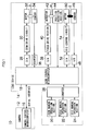
- Fig. 1 is a block diagram showing the main configuration of a control system in the camera system according to the embodiment of the present invention.
- a camera system 10 comprises a camera 12 and a lens device 14.
- a camera control microcomputer 16 in the camera 12 comprises ROM for storing a control program and kinds of data tables necessary for control and operation and RAM or the like used as a working storage area, and the microcomputer 16 controls devices in the camera 12 according to predetermined programs.
- a lens control microcomputer 18 in the lens device 14 comprises ROM for storing a control program and kinds of data tables necessary for control and operation and RAM or the like used as a working storage area, and the microcomputer 18 controls devices in the lens device 14 according to predetermined programs.
- the camera control microcomputer 16 and the lens control microcomputer 18 are serially connected to each other via a serial interface (SCI) of the lens device 14.
- SCI serial interface
- the lens device 14 comprises a zoom manual operation section 20, a focus manual operation section 22, and an iris manual operation section 24 which manually operate zoom, focus, and an iris.
- the zoom manual operation section 20 is, for example, a zoom ring which is rotatably attached on the outer periphery of the lens device 14.
- the direction and amount of rotation of the zoom ring are converted, by a counter 26, to zoom demand data for providing an instruction on the moving speed of zoom lenses ZL, and the data is outputted to the lens control microcomputer 18.
- the lens control microcomputer 18 calculates the amounts of movement or the like of the zoom lenses ZL based on the zoom demand data obtained from the counter 26 and position data on the zoom lenses ZL.
- the position data has been inputted from a sensor 34 through a counter 36.
- the lens control microcomputer 18 outputs a zoom control signal including data on the amounts of movement of the zoom lenses ZL.
- the amounts of movement have been obtained by operation.
- the zoom control signal is converted to an analog signal by a DA converter 28 and outputted to a zoom drive circuit 30.
- the zoom drive circuit 30 controls a zoom motor 32 in response to the zoom control signal to drive the zoom lenses ZL of the lens device
- the focus manual operation section 22 is, for example, a focus ring attached on the outer periphery of the lens device 14.
- the direction and amount of rotation of the focus ring are converted, by the counter 26, to focus demand data (local position command LP) for providing an instruction on the moving positions of focus lenses FL, and the data is outputted to the lens control microcomputer 18.
- the lens control microcomputer 18 outputs a focus control signal based on the focus demand data.
- the focus control signal is converted to an analog signal by a DA converter 38 and outputted to a focus drive section 40.
- the focus drive section 40 controls an actuator 42 based on the focus control signal and the positions of focus lenses FL to drive the focus lenses FL.
- the positions of the focus lenses FL have been detected by a position detection section 44.
- a sensor 46 for iris I outputs F number data to the lens control microcomputer 18.
- the F number data is converted to a digital signal by an AD converter 48 and inputted to the lens control microcomputer 18.
- the lens control microcomputer 18 calculates the amount of drive of a meter 50 based on the F number data and an iris control signal inputted from the iris manual operation section 24 through the counter 26, and the lens control microcomputer 18 outputs an iris control signal including data on the amount of drive.
- the iris control signal is converted to an analog signal by a DA converter 52 and outputted to an iris control circuit 54.
- the F number data obtained by the sensor 46 for iris I may be inputted to the iris control circuit 54 and the amount of drive of the meter 50 may be calculated by the iris control circuit 54.
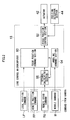
- Fig. 2 is a block diagram showing the main configuration of the focus control mechanism of the camera system 10.
- focus control of the lens device 14 is performed in response to a manual operation from the focus manual operation section 22 or a remote command from the camera 12.
- focus control section 22 When the focus manual operation section 22 (focus ring) is operated, the direction and amount of rotation of the focus manual operation section 22 are converted, by the counter 26, to focus demand data (local position command LPCtrl) for providing an instruction on the moving positions of focus lenses FL, and the data is outputted to the lens control microcomputer 18.
- a focus position command section 60 calculates moving target positions of the focus lenses FL in response to the local position command LP, and outputs the positions to a focus position control section 62. Then, the focus position control section 62 calculates the amounts of movement or the like of the focus lenses FL based on the moving target positions and position data on the focus lenses FL, the position data being inputted from the position detection section 44. After that, the focus position control section 62 outputs a focus control signal including the data on the amounts of movement to the focus drive section 40 (not shown in Fig. 2). Thus the focus lenses FL are driven and moved to the moving target positions.
- the lens control microcomputer 18 calculates a focal depth d of the lens device 14.
- a wobbling command section 64 obtains a wobble movement amount command value WobCtrl from a Wobble command W inputted from the camera 12. Based on the wobble movement amount command value WobCtrl obtained from the camera 12 and the calculated focal depth d, a wobble amount Wob is calculated.
- the coefficient ⁇ is preferably within the range of 0 ⁇
- the coefficient ⁇ is set within the range of 0 ⁇
- the smaller wobble amount Wob the more visually natural image is obtained.
- the coefficient ⁇ is set within a range that enables detection of the best focus direction with ease.
- the focal depth d changes with the F number Fno, and thus the wobble amount Wob also changes with the F number Fno.
- the focus position control section 62 calculates the amounts of movement or the like of the focus lenses FL based on the focus position command value FPCtrlOP and position data on the focus lenses FL, the position data being inputted from the position detection section 44. After that, the focus position control section 62 outputs a focus control signal including the data on the amounts of movement to the focus drive section 40.
- the focus lenses FL are driven by the focus drive section 40 and wobbled around the focus position command value FPCtrl by
- the lens control microcomputer 18 calculates the focal depth d of the lens device 14 according to Equation (1). Further, the wobbling command section 64 obtains the wobble movement amount command value WobCtrl from the Wobble command W inputted from the camera 12 and calculates the wobble amount Wob according to Equation (2).
- the lens control microcomputer 18 obtains a command to move the focus lenses FL at a speed AFSpeedCtrl which is ⁇ times as large as the focal depth d per unit time.
- an integral calculating section 66 integrates the speed AFSpeedCtrl to calculate a movement amount command value LAFSCtrl of the focus lenses FL per unit time (for example, 1 ms).
- the focus position command section 60 calculates the maximum value AFSCtrlMax of the amounts of movement of the focus lenses FL per unit time in consideration of the calculated wobble amount Wob.
- the maximum value AFSCtrlMax is determined based on the limit value of the moving speed when the focus lenses FL are moved while wobbling with the wobble amount Wob, and the maximum value AFSCtrlMax of the amounts of movement of the focus lenses FL per unit time is stored, for each value of the wobble amount Wob, in the memory (RAM or the like) of the lens control microcomputer 18.
- the focus position command section 60 refers to the memory to calculate the maximum value AFSCtrlMax.
- a moving amount PAFSCtrl of the focus lenses FL is calculated per unit time is calculated.
- PAFSCtrl AFSCtrlMax is established.
- the command value LAFSCtrl is smaller than the maximum value AFSCtrlMax (LAFSCtrl ⁇ AFSCtrlMax)
- PAFSCtrl LAFSCtrl is established.
- the moving amount PAFSCtrl is added to the focus position command value AFSCtrl of the previous processing (or the initial positions of the focus lenses FL at the first processing) as follows:
- a ⁇ F ⁇ S ⁇ C ⁇ t ⁇ r ⁇ l A ⁇ F ⁇ S ⁇ C ⁇ t ⁇ r ⁇ l + P ⁇ A ⁇ F ⁇ S ⁇ C ⁇ t ⁇ r ⁇ l
- the focus position control section 62 calculates the amounts of movement or the like of the focus lenses FL based on the focus position command value FPCtrlOP and position data on the focus lenses FL, the position data being inputted from the position detection section 44. After that, the focus position control section 62 outputs a focus control signal including the data on the amounts of movement to the focus drive section 40.
- the focus lenses FL are driven by the focus drive section 40 and wobbled around the focus position command value FPCtrl by
- Fig. 3 is a graph schematically showing changes in the positions of the focus lenses FL.
- Broken line L10 of Fig. 3 is a plot of the added moving amounts PAFSCtrl of the focus lenses FL per unit time. The inclination of the broken line L10 corresponds to the moving amount PAFSCtrl.
- solid line L20 is a plot of the movements of the focus lenses FL which move while wobbling.
- the moving amount PAFSCtrl AFSCtrlMax is established. Therefore, by extending the plot L10, a straight line with an inclination of AFSCtrlMax is obtained as indicated by broken line L11. Thus the wobbling operation can be correctly performed.
- Fig. 4 is a flowchart showing the flow of focus control.
- the focus position command value FPCtrlOP is calculated (focus control: step S10).
- the position detection section 44 detects the positions of the focus lenses FL (step S12).
- the focus position control section 62 calculates the amounts of movement or the like of the focus lenses FL based on the focus position command value FPCtrlOP and position data on the focus lenses FL, the position data being inputted from the position detection section 44.
- the focus position control section 62 outputs the focus control signal including the data on the amounts of movement to the focus drive section 40.
- the focus lenses FL are driven by the focus drive section 40 and wobbled around the focus position command value FPCtrl by
- the best focus position is detected by the camera control microcomputer 16 and the focus lenses FL are moved to the best focus position (focus operation: step S14).
- Fig. 5 is a flowchart showing the focus control process of Fig. 4.
- the lens control microcomputer 18 always detects the operation of the focus ring in response to a signal from the counter 26.
- focus is manually controlled based on the local position command LP (local processing: step S24).
- focus is remotely controlled based on the remote position command RP or the remote speed command RS (remote processing: step S26).
- Fig. 6 is a flowchart showing the process of the remote processing of Fig. 5.
- the lens control microcomputer 18 calculates the focal depth d of the lens device 14 according to Equation (1) (step S30).
- the wobbling command section 64 obtains the wobble movement amount command value WobCtrl from the Wobble command W inputted from the camera 12 and calculates the wobble amount Wob according to Equation (2) (step S32).
- the focus position command section 60 calculates the focus position command value FPCtrl in response to the remote position command RP inputted from the camera 12 (step S36). After that, as expressed in Equation (3), the focus position command section 60 adds the wobble amount Wob to the focus position command value FPCtrl to calculate the focus position command value FPCtrlOP in consideration of the wobble amount Wob (step S38). Thus based on the remote position command RP, the focus position command value FPCtrlOP is calculated in consideration of the wobble amount Wob.
- the lens control microcomputer 18 obtains, from the remote speed command RS inputted from the camera 12, a command to move the focus lenses FL at the speed AFSpeedCtrl which is a times as large as the focal depth d per unit time. Then, the integral calculating section 66 integrates the speed AFSpeedCtrl to calculate the movement amount command values LAFSCtrl of the focus lenses FL per unit time (for example, 1 ms) (step S40).
- the focus position command section 60 calculates the maximum value AFSCtrlMax of the amounts of movement of the focus lenses FL per unit time in consideration of the calculated wobble amount Wob (step S42). Then, based on the command value LAFSCtrl and the maximum value AFSCtrlMax, the moving amount PAFSCtrl of the focus lenses FL is determined per unit time (step S44).
- the command value LAFSCtrl is smaller than the maximum value AFSCtrlMax (LAFSCtrl ⁇ AFSCtrlMax)
- PAFSCtrl LAFSCtrl is established.
- the moving amount PAFSCtrl is added to the focus position command value AFSCtrl of the previous processing (or the initial positions of the focus lenses FL) to calculated the focus position command value AFSCtrl (step S46).
- the wobble amount Wob is added to the value of AFSCtrl having been obtained by Equation (4) (see Equation (5)), so that the focus position command value FPCtrlOP is calculated in consideration of the wobble amount Wob (step S48).
- the focus position command value FPCtrlOP is calculated in consideration of the wobble amount Wob.
- focus control is performed by the lens control microcomputer 18 of the lens device 14.
- the focus lenses FL may be directly controlled by the camera control microcomputer 16.
- the maximum value AFSCtrlMax may be set according to the zoom positions of the zoom lenses ZL.
Landscapes
- Physics & Mathematics (AREA)
- Engineering & Computer Science (AREA)
- Computer Vision & Pattern Recognition (AREA)
- General Physics & Mathematics (AREA)
- Optics & Photonics (AREA)
- Automatic Focus Adjustment (AREA)
- Studio Devices (AREA)
- Focusing (AREA)
Abstract
Description
- The present invention relates to a camera system and particularly relates to art used for detecting focus in autofocus control of a taking lens.
- Conventionally, arts for detecting the best focus position through wobbling are proposed. For example,
Japanese Patent Application Laid-Open No. 5-107451 - In the case where the focus lens is driven in response to a wobbling command from a control unit of a camera and a moving speed command of the focus lens, a too large speed command value disables a correct wobbling operation, resulting in an erroneous decision of the best focus direction (in-focus direction).
- The present invention is designed in view of these circumstances. An object of the present invention is to provide a camera system which can enable a correct wobbling operation and accurately decide the best focus direction when driving a focus lens in response to a wobbling command and a moving speed command of the focus lens.
- In order to attain the object, a camera system according to a first aspect of the present invention comprises: an imaging optical system including a focus lens, a driving device which drives the focus lens, a moving speed command value input device which inputs a moving speed command value of the focus lens, a wobble amount calculating device which calculates a wobble amount for wobbling the focus lens, a moving amount command value calculating device which calculates a command value of the amount of movement of the focus lens per unit time based on the inputted moving speed command value, a moving amount maximum value calculating device which calculates the maximum value of the amount of movement of the focus lens per unit time in consideration of the wobble amount, a moving amount determining device which sets, when the command value is larger than or equal to the maximum value, the maximum value as the amount of movement of the focus lens per unit time, and sets, when the command value is smaller than the maximum value, the command value as the amount of movement of the focus lens per unit time, a focus position command value calculating device which calculates a focus position command value based on the determined amount of movement of the focus lens per unit time, a best focus direction detecting device which detects the best focus direction when the focus lens is driven to the position of the focus position command value by the driving device while wobbling, and a control device which moves the focus lens to the best focus position based on the detected best focus direction.
- According to the camera system of the first aspect, the maximum value of the amount of movement of the focus lens per unit time is set according to the wobble amount, so that a correct wobbling operation can be performed and the best focus direction can be correctly determined.
- A camera system according to a second aspect of the present invention, in the first aspect, further comprises: a focal depth calculating device which calculates the focal depth of the imaging optical system, wherein the wobbling amount calculating device calculates the wobble amount based on the focal depth.
- According to the camera system of the second aspect, defocusing can be prevented during the movement of the focus lens by, for example, making the wobble amount smaller than the focal depth, so that an unnatural image can be prevented.
- According to the present invention, the maximum value of the amount of movement of the focus lens per unit time is set according to the wobble amount, so that a correct wobbling operation can be performed and the best focus direction can be correctly determined.
-
- Fig. 1 is a block diagram showing the main configuration of a control system in a camera system according to an embodiment of the present invention;
- Fig. 2 is a block diagram showing the main configuration of a focus control mechanism of a
camera system 10; - Fig. 3 is a graph schematically showing changes in the positions of focus lenses FL;
- Fig. 4 is a flowchart showing the flow of focus control;
- Fig. 5 is a flowchart showing a focus control process of Fig. 4; and
- Fig. 6 is a flowchart showing the process of remote processing of Fig. 5.
- The following will describe a preferred embodiment of a camera system of the present invention in accordance with the accompanying drawings.
- Fig. 1 is a block diagram showing the main configuration of a control system in the camera system according to the embodiment of the present invention. As shown in Fig. 1, a
camera system 10 comprises acamera 12 and alens device 14. - A
camera control microcomputer 16 in thecamera 12 comprises ROM for storing a control program and kinds of data tables necessary for control and operation and RAM or the like used as a working storage area, and themicrocomputer 16 controls devices in thecamera 12 according to predetermined programs. Alens control microcomputer 18 in thelens device 14 comprises ROM for storing a control program and kinds of data tables necessary for control and operation and RAM or the like used as a working storage area, and themicrocomputer 18 controls devices in thelens device 14 according to predetermined programs. Thecamera control microcomputer 16 and thelens control microcomputer 18 are serially connected to each other via a serial interface (SCI) of thelens device 14. - As shown in Fig. 1, the
lens device 14 comprises a zoommanual operation section 20, a focusmanual operation section 22, and an irismanual operation section 24 which manually operate zoom, focus, and an iris. - The zoom
manual operation section 20 is, for example, a zoom ring which is rotatably attached on the outer periphery of thelens device 14. The direction and amount of rotation of the zoom ring are converted, by acounter 26, to zoom demand data for providing an instruction on the moving speed of zoom lenses ZL, and the data is outputted to thelens control microcomputer 18. Thelens control microcomputer 18 calculates the amounts of movement or the like of the zoom lenses ZL based on the zoom demand data obtained from thecounter 26 and position data on the zoom lenses ZL. The position data has been inputted from asensor 34 through acounter 36. Thelens control microcomputer 18 outputs a zoom control signal including data on the amounts of movement of the zoom lenses ZL. The amounts of movement have been obtained by operation. The zoom control signal is converted to an analog signal by aDA converter 28 and outputted to azoom drive circuit 30. Thezoom drive circuit 30 controls azoom motor 32 in response to the zoom control signal to drive the zoom lenses ZL of thelens device 14. - The focus
manual operation section 22 is, for example, a focus ring attached on the outer periphery of thelens device 14. The direction and amount of rotation of the focus ring are converted, by thecounter 26, to focus demand data (local position command LP) for providing an instruction on the moving positions of focus lenses FL, and the data is outputted to thelens control microcomputer 18. Thelens control microcomputer 18 outputs a focus control signal based on the focus demand data. The focus control signal is converted to an analog signal by aDA converter 38 and outputted to afocus drive section 40. Thefocus drive section 40 controls anactuator 42 based on the focus control signal and the positions of focus lenses FL to drive the focus lenses FL. The positions of the focus lenses FL have been detected by aposition detection section 44. - A
sensor 46 for iris I outputs F number data to thelens control microcomputer 18. The F number data is converted to a digital signal by anAD converter 48 and inputted to thelens control microcomputer 18. Thelens control microcomputer 18 calculates the amount of drive of ameter 50 based on the F number data and an iris control signal inputted from the irismanual operation section 24 through thecounter 26, and thelens control microcomputer 18 outputs an iris control signal including data on the amount of drive. The iris control signal is converted to an analog signal by aDA converter 52 and outputted to aniris control circuit 54. The F number data obtained by thesensor 46 for iris I may be inputted to theiris control circuit 54 and the amount of drive of themeter 50 may be calculated by theiris control circuit 54. - Fig. 2 is a block diagram showing the main configuration of the focus control mechanism of the
camera system 10. In thecamera system 10 of the present embodiment, focus control of thelens device 14 is performed in response to a manual operation from the focusmanual operation section 22 or a remote command from thecamera 12. - First, the following will describe focus control through a manual operation. When the focus manual operation section 22 (focus ring) is operated, the direction and amount of rotation of the focus
manual operation section 22 are converted, by thecounter 26, to focus demand data (local position command LPCtrl) for providing an instruction on the moving positions of focus lenses FL, and the data is outputted to thelens control microcomputer 18. A focusposition command section 60 calculates moving target positions of the focus lenses FL in response to the local position command LP, and outputs the positions to a focusposition control section 62. Then, the focusposition control section 62 calculates the amounts of movement or the like of the focus lenses FL based on the moving target positions and position data on the focus lenses FL, the position data being inputted from theposition detection section 44. After that, the focusposition control section 62 outputs a focus control signal including the data on the amounts of movement to the focus drive section 40 (not shown in Fig. 2). Thus the focus lenses FL are driven and moved to the moving target positions. - The following will describe focus control responding to a remote position command RP from the
camera 12. First, thelens control microcomputer 18 calculates a focal depth d of thelens device 14. The focal depth d is expressed as below:
where δ designates the radius of the minimum circle of confusion of thelens device 14 and Fno designates F number. - Then, a
wobbling command section 64 obtains a wobble movement amount command value WobCtrl from a Wobble command W inputted from thecamera 12. Based on the wobble movement amount command value WobCtrl obtained from thecamera 12 and the calculated focal depth d, a wobble amount Wob is calculated. The wobble amount Wob is, for example, α times as large as the focal depth d as below:
The coefficient α is preferably within the range of 0 < |α| < 1. For example, the coefficient α is ±1/4. The coefficient α is set within the range of 0 < |α| < 1 because generally the wobble amount Wob smaller than or equal to the focal depth d is not visible in an image with a wobbling operation. The smaller wobble amount Wob, the more visually natural image is obtained. However, it becomes difficult to detect the best focus direction, and thus the coefficient α is set within a range that enables detection of the best focus direction with ease. As expressed in Equation (1), the focal depth d changes with the F number Fno, and thus the wobble amount Wob also changes with the F number Fno. - Then, the focus
position command section 60 calculates a focus position command value FPCtrl in response to the remote position command RP inputted from thecamera 12. After that, the wobble amount Wob is added to the focus position command value FPCtrl to calculate a focus position command value FPCtrlOP as follows:
- Then, the focus
position control section 62 calculates the amounts of movement or the like of the focus lenses FL based on the focus position command value FPCtrlOP and position data on the focus lenses FL, the position data being inputted from theposition detection section 44. After that, the focusposition control section 62 outputs a focus control signal including the data on the amounts of movement to thefocus drive section 40. The focus lenses FL are driven by thefocus drive section 40 and wobbled around the focus position command value FPCtrl by |Wob|. Thus the best focus position is detected by thecamera control microcomputer 16 and the focus lenses FL are moved to the best focus position. - The following will describe focus control responding to a remote speed command RS from the
camera 12. First, thelens control microcomputer 18 calculates the focal depth d of thelens device 14 according to Equation (1). Further, the wobblingcommand section 64 obtains the wobble movement amount command value WobCtrl from the Wobble command W inputted from thecamera 12 and calculates the wobble amount Wob according to Equation (2). - Then, from the remote speed command RS inputted from the
camera 12, thelens control microcomputer 18 obtains a command to move the focus lenses FL at a speed AFSpeedCtrl which is α times as large as the focal depth d per unit time. After that, an integral calculatingsection 66 integrates the speed AFSpeedCtrl to calculate a movement amount command value LAFSCtrl of the focus lenses FL per unit time (for example, 1 ms). - Then, the focus
position command section 60 calculates the maximum value AFSCtrlMax of the amounts of movement of the focus lenses FL per unit time in consideration of the calculated wobble amount Wob. In this case, the maximum value AFSCtrlMax is determined based on the limit value of the moving speed when the focus lenses FL are moved while wobbling with the wobble amount Wob, and the maximum value AFSCtrlMax of the amounts of movement of the focus lenses FL per unit time is stored, for each value of the wobble amount Wob, in the memory (RAM or the like) of thelens control microcomputer 18. The focusposition command section 60 refers to the memory to calculate the maximum value AFSCtrlMax. - Then, based on the command value LAFSCtrl and the maximum value AFSCtrlMax, a moving amount PAFSCtrl of the focus lenses FL is calculated per unit time is calculated. When the command value LAFSCtrl is larger than or equal to the maximum value AFSCtrlMax (LAFSCtrl ≥ AFSCtrlMax), PAFSCtrl = AFSCtrlMax is established. When the command value LAFSCtrl is smaller than the maximum value AFSCtrlMax (LAFSCtrl < AFSCtrlMax), PAFSCtrl = LAFSCtrl is established.
- Then, the moving amount PAFSCtrl is added to the focus position command value AFSCtrl of the previous processing (or the initial positions of the focus lenses FL at the first processing) as follows:

- Thereafter, the wobble amount Wob is added to the value of AFSCtrl having been obtained by Equation (4), so that a focus position command value FPCtrIOP is calculated in consideration of the wobble amount Wob as follows:

- Then, the focus
position control section 62 calculates the amounts of movement or the like of the focus lenses FL based on the focus position command value FPCtrlOP and position data on the focus lenses FL, the position data being inputted from theposition detection section 44. After that, the focusposition control section 62 outputs a focus control signal including the data on the amounts of movement to thefocus drive section 40. The focus lenses FL are driven by thefocus drive section 40 and wobbled around the focus position command value FPCtrl by |Wob|. Thus the best focus position is detected by thecamera control microcomputer 16 and the focus lenses FL are moved to the best focus position. - Fig. 3 is a graph schematically showing changes in the positions of the focus lenses FL. Broken line L10 of Fig. 3 is a plot of the added moving amounts PAFSCtrl of the focus lenses FL per unit time. The inclination of the broken line L10 corresponds to the moving amount PAFSCtrl. Further, solid line L20 is a plot of the movements of the focus lenses FL which move while wobbling.
- As the speed command value AFSpeedCtrl of the remote speed command RS increases, the moving amount command value AFSCtrl of the focus lenses FL increases, so that the plot L10 inclines more sharply as indicated by thin broken line L12. For this reason, as indicated by solid line L22, a higher speed is demanded of the wobbling operation and thus it becomes difficult to perform a correct wobbling operation.
- In the present embodiment, when the command value AFSCtrl is larger than or equal to the maximum value AFSCtrlMax, the moving amount PAFSCtrl = AFSCtrlMax is established. Therefore, by extending the plot L10, a straight line with an inclination of AFSCtrlMax is obtained as indicated by broken line L11. Thus the wobbling operation can be correctly performed.
- Referring to Figs. 4 to 6, focus control of the present embodiment will be discussed below. Fig. 4 is a flowchart showing the flow of focus control. First, in response to a manual operation (local position command LP) from the focus
manual operation section 22 or a remote command (remote position command RP or remote speed command RS) from thecamera 12, the focus position command value FPCtrlOP is calculated (focus control: step S10). Then, theposition detection section 44 detects the positions of the focus lenses FL (step S12). Then, the focusposition control section 62 calculates the amounts of movement or the like of the focus lenses FL based on the focus position command value FPCtrlOP and position data on the focus lenses FL, the position data being inputted from theposition detection section 44. After that, the focusposition control section 62 outputs the focus control signal including the data on the amounts of movement to thefocus drive section 40. The focus lenses FL are driven by thefocus drive section 40 and wobbled around the focus position command value FPCtrl by |Wob|. Thus the best focus position is detected by thecamera control microcomputer 16 and the focus lenses FL are moved to the best focus position (focus operation: step S14). - Fig. 5 is a flowchart showing the focus control process of Fig. 4. First, it is detected whether an input operation is performed by the focus manual operation section 22 (focus ring) (step S20). The
lens control microcomputer 18 always detects the operation of the focus ring in response to a signal from thecounter 26. When the operation of the focus ring is detected (local in step S22), focus is manually controlled based on the local position command LP (local processing: step S24). On the other hand, when the operation of the focus ring is not detected and the remote position command RP or the remote speed command RS is received from the camera 12 (remote in step S22), focus is remotely controlled based on the remote position command RP or the remote speed command RS (remote processing: step S26). - Fig. 6 is a flowchart showing the process of the remote processing of Fig. 5. First, the
lens control microcomputer 18 calculates the focal depth d of thelens device 14 according to Equation (1) (step S30). Further, the wobblingcommand section 64 obtains the wobble movement amount command value WobCtrl from the Wobble command W inputted from thecamera 12 and calculates the wobble amount Wob according to Equation (2) (step S32). - Then, in the case of focus control responding to the remote position command RP from the camera 12 (position control of step S34), the focus
position command section 60 calculates the focus position command value FPCtrl in response to the remote position command RP inputted from the camera 12 (step S36). After that, as expressed in Equation (3), the focusposition command section 60 adds the wobble amount Wob to the focus position command value FPCtrl to calculate the focus position command value FPCtrlOP in consideration of the wobble amount Wob (step S38). Thus based on the remote position command RP, the focus position command value FPCtrlOP is calculated in consideration of the wobble amount Wob. - On the other hand, in the case of focus control responding to the remote speed command RS from the camera 12 (speed control in step S34), the
lens control microcomputer 18 obtains, from the remote speed command RS inputted from thecamera 12, a command to move the focus lenses FL at the speed AFSpeedCtrl which is a times as large as the focal depth d per unit time. Then, the integral calculatingsection 66 integrates the speed AFSpeedCtrl to calculate the movement amount command values LAFSCtrl of the focus lenses FL per unit time (for example, 1 ms) (step S40). - Then, the focus
position command section 60 calculates the maximum value AFSCtrlMax of the amounts of movement of the focus lenses FL per unit time in consideration of the calculated wobble amount Wob (step S42). Then, based on the command value LAFSCtrl and the maximum value AFSCtrlMax, the moving amount PAFSCtrl of the focus lenses FL is determined per unit time (step S44). In step S44, when the command value LAFSCtrl is larger than or equal to the maximum value AFSCtrlMax (LAFSCtrl ≥ AFSCtrlMax), PAFSCtrl = AFSCtrlMax is established. When the command value LAFSCtrl is smaller than the maximum value AFSCtrlMax (LAFSCtrl < AFSCtrlMax), PAFSCtrl = LAFSCtrl is established. - Then, as expressed in Equation (4), the moving amount PAFSCtrl is added to the focus position command value AFSCtrl of the previous processing (or the initial positions of the focus lenses FL) to calculated the focus position command value AFSCtrl (step S46). After that, the wobble amount Wob is added to the value of AFSCtrl having been obtained by Equation (4) (see Equation (5)), so that the focus position command value FPCtrlOP is calculated in consideration of the wobble amount Wob (step S48). Thus based on the remote speed command RS, the focus position command value FPCtrlOP is calculated in consideration of the wobble amount Wob.
- In the
camera system 10 of the present embodiment, focus control is performed by thelens control microcomputer 18 of thelens device 14. The focus lenses FL may be directly controlled by thecamera control microcomputer 16. - In the case where focusing and zooming are simultaneously performed in the present embodiment, the maximum value AFSCtrlMax may be set according to the zoom positions of the zoom lenses ZL.
Claims (2)
- A camera system (10), comprising:an imaging optical system including a focus lens (FL),a driving device (40) which drives the focus lens (FL),a moving speed command value input device which inputs a moving speed command value of the focus lens (FL),a wobble amount calculating device which calculates a wobble amount for wobbling the focus lens (FL),a moving amount command value calculating device which calculates a command value of an amount of movement of the focus lens (FL) per unit time based on the inputted moving speed command value,a moving amount maximum value calculating device which calculates a maximum value of the amount of movement of the focus lens (FL) per unit time in consideration of the wobble amount,a moving amount determining device which sets, when the command value is larger than or equal to the maximum value, the maximum value as the amount of movement of the focus lens (FL) per unit time, and sets, when the command value is smaller than the maximum value, the command value as the amount of movement of the focus lens (FL) per unit time,a focus position command value calculating device which calculates a focus position command value based on the determined amount of movement of the focus lens (FL) per unit time,a best focus direction detecting device which detects a best focus direction when the focus lens (FL) is driven to a position of the focus position command value by the driving device (40) while wobbling, anda control device which moves the focus lens (FL) to the best focus position based on the detected best focus direction.
- The camera system (10) according to claim 1, further comprising: a focal depth calculating device which calculates a focal depth of the imaging optical system,
wherein the wobbling amount calculating device calculates the wobble amount based on the focal depth.
Applications Claiming Priority (1)
| Application Number | Priority Date | Filing Date | Title |
|---|---|---|---|
| JP2005274112A JP4618072B2 (en) | 2005-09-21 | 2005-09-21 | Camera system |
Publications (2)
| Publication Number | Publication Date |
|---|---|
| EP1767974A1 true EP1767974A1 (en) | 2007-03-28 |
| EP1767974B1 EP1767974B1 (en) | 2007-11-21 |
Family
ID=37456156
Family Applications (1)
| Application Number | Title | Priority Date | Filing Date |
|---|---|---|---|
| EP06019687A Ceased EP1767974B1 (en) | 2005-09-21 | 2006-09-20 | Camera system |
Country Status (4)
| Country | Link |
|---|---|
| US (1) | US7522829B2 (en) |
| EP (1) | EP1767974B1 (en) |
| JP (1) | JP4618072B2 (en) |
| DE (1) | DE602006000260T2 (en) |
Families Citing this family (1)
| Publication number | Priority date | Publication date | Assignee | Title |
|---|---|---|---|---|
| JP5328384B2 (en) * | 2009-01-14 | 2013-10-30 | キヤノン株式会社 | LENS CONTROL DEVICE, OPTICAL DEVICE, AND LENS CONTROL METHOD |
Citations (4)
| Publication number | Priority date | Publication date | Assignee | Title |
|---|---|---|---|---|
| US5140357A (en) * | 1989-12-18 | 1992-08-18 | Canon Kabushiki Kaisha | Automatic focusing device wherein loop gain is set responsively to variation of magnification |
| JPH05107451A (en) * | 1991-10-18 | 1993-04-30 | Mitsubishi Electric Corp | Autofocus device |
| EP0756187A2 (en) * | 1995-07-28 | 1997-01-29 | Canon Kabushiki Kaisha | Mechanism for oscillating a lens in an automatic focus detection objective |
| WO2005085927A1 (en) * | 2004-03-02 | 2005-09-15 | Sony Corporation | Autofocus controlling apparatus and method, recording medium, and program |
Family Cites Families (3)
| Publication number | Priority date | Publication date | Assignee | Title |
|---|---|---|---|---|
| JP3689497B2 (en) * | 1996-07-30 | 2005-08-31 | キヤノン株式会社 | Automatic focusing method and apparatus |
| JP2985126B2 (en) * | 1997-07-08 | 1999-11-29 | 株式会社ニコン | Focus detection camera |
| JP4323964B2 (en) * | 2004-01-05 | 2009-09-02 | キヤノン株式会社 | Imaging apparatus and control method thereof |
-
2005
- 2005-09-21 JP JP2005274112A patent/JP4618072B2/en not_active Expired - Fee Related
-
2006
- 2006-09-20 DE DE602006000260T patent/DE602006000260T2/en active Active
- 2006-09-20 US US11/523,639 patent/US7522829B2/en not_active Expired - Fee Related
- 2006-09-20 EP EP06019687A patent/EP1767974B1/en not_active Ceased
Patent Citations (5)
| Publication number | Priority date | Publication date | Assignee | Title |
|---|---|---|---|---|
| US5140357A (en) * | 1989-12-18 | 1992-08-18 | Canon Kabushiki Kaisha | Automatic focusing device wherein loop gain is set responsively to variation of magnification |
| JPH05107451A (en) * | 1991-10-18 | 1993-04-30 | Mitsubishi Electric Corp | Autofocus device |
| EP0756187A2 (en) * | 1995-07-28 | 1997-01-29 | Canon Kabushiki Kaisha | Mechanism for oscillating a lens in an automatic focus detection objective |
| WO2005085927A1 (en) * | 2004-03-02 | 2005-09-15 | Sony Corporation | Autofocus controlling apparatus and method, recording medium, and program |
| EP1722259A1 (en) * | 2004-03-02 | 2006-11-15 | Sony Corporation | Autofocus controlling apparatus and method, recording medium, and program |
Also Published As
| Publication number | Publication date |
|---|---|
| US7522829B2 (en) | 2009-04-21 |
| US20070065133A1 (en) | 2007-03-22 |
| JP4618072B2 (en) | 2011-01-26 |
| JP2007086326A (en) | 2007-04-05 |
| DE602006000260T2 (en) | 2008-10-16 |
| EP1767974B1 (en) | 2007-11-21 |
| DE602006000260D1 (en) | 2008-01-03 |
Similar Documents
| Publication | Publication Date | Title |
|---|---|---|
| US4890133A (en) | Autofocus camera | |
| US8964105B2 (en) | Auto-focus controlling apparatus, electronic imaging apparatus and digital still camera | |
| US5325145A (en) | Camera system | |
| USRE33830E (en) | Auto-focus system for video camera | |
| US6115552A (en) | Lens device and optical apparatus | |
| CN106054350B (en) | Optical device and display control method | |
| JP5868109B2 (en) | Optical apparatus, lens barrel, and automatic focusing method | |
| JP5173210B2 (en) | Optical apparatus having focus lens and zoom lens driving means | |
| JP2004177919A (en) | Zoom lens control device and photographing system | |
| EP1939681B1 (en) | Optical apparatus and image-pickup system | |
| JP2963006B2 (en) | Camera device | |
| US11002940B2 (en) | Control apparatus, optical apparatus, and control method for optical apparatus | |
| EP3547002A2 (en) | Lens apparatus and image pickup apparatus | |
| EP1975696B1 (en) | Lens apparatus and image taking apparatus using the same | |
| JP6639117B2 (en) | Optical equipment and focus control program | |
| EP1767974B1 (en) | Camera system | |
| JP2004219581A (en) | Automatic focusing device | |
| EP1081524B1 (en) | TV zoom lens system and apparatus | |
| JP2017026770A (en) | Manual focus control of lens barrel and electronic display means | |
| JP4579572B2 (en) | Drive control device for optical equipment | |
| US7756406B2 (en) | Photographic apparatus and interchangeable camera lens | |
| JP6700698B2 (en) | Optical device, display control method, and display control program | |
| JPH07301747A (en) | Optical device having focus detection device | |
| JP2025035544A (en) | CONTROL DEVICE, LENS DEVICE, IMAGING DEVICE, CONTROL METHOD, AND PROGRAM | |
| JP4478173B2 (en) | Imaging device |
Legal Events
| Date | Code | Title | Description |
|---|---|---|---|
| PUAI | Public reference made under article 153(3) epc to a published international application that has entered the european phase |
Free format text: ORIGINAL CODE: 0009012 |
|
| 17P | Request for examination filed |
Effective date: 20060920 |
|
| AK | Designated contracting states |
Kind code of ref document: A1 Designated state(s): AT BE BG CH CY CZ DE DK EE ES FI FR GB GR HU IE IS IT LI LT LU LV MC NL PL PT RO SE SI SK TR |
|
| AX | Request for extension of the european patent |
Extension state: AL BA HR MK YU |
|
| GRAP | Despatch of communication of intention to grant a patent |
Free format text: ORIGINAL CODE: EPIDOSNIGR1 |
|
| GRAS | Grant fee paid |
Free format text: ORIGINAL CODE: EPIDOSNIGR3 |
|
| GRAA | (expected) grant |
Free format text: ORIGINAL CODE: 0009210 |
|
| AK | Designated contracting states |
Kind code of ref document: B1 Designated state(s): AT BE BG CH CY CZ DE DK EE ES FI FR GB GR HU IE IS IT LI LT LU LV MC NL PL PT RO SE SI SK TR |
|
| REG | Reference to a national code |
Ref country code: GB Ref legal event code: FG4D |
|
| AKX | Designation fees paid |
Designated state(s): AT BE BG CH CY CZ DE DK EE ES FI FR GB GR HU IE IS IT LI LT LU LV MC NL PL PT RO SE SI SK TR |
|
| REG | Reference to a national code |
Ref country code: IE Ref legal event code: FG4D |
|
| REG | Reference to a national code |
Ref country code: CH Ref legal event code: EP |
|
| REF | Corresponds to: |
Ref document number: 602006000260 Country of ref document: DE Date of ref document: 20080103 Kind code of ref document: P |
|
| PG25 | Lapsed in a contracting state [announced via postgrant information from national office to epo] |
Ref country code: ES Free format text: LAPSE BECAUSE OF FAILURE TO SUBMIT A TRANSLATION OF THE DESCRIPTION OR TO PAY THE FEE WITHIN THE PRESCRIBED TIME-LIMIT Effective date: 20080304 Ref country code: LI Free format text: LAPSE BECAUSE OF FAILURE TO SUBMIT A TRANSLATION OF THE DESCRIPTION OR TO PAY THE FEE WITHIN THE PRESCRIBED TIME-LIMIT Effective date: 20071121 Ref country code: CH Free format text: LAPSE BECAUSE OF FAILURE TO SUBMIT A TRANSLATION OF THE DESCRIPTION OR TO PAY THE FEE WITHIN THE PRESCRIBED TIME-LIMIT Effective date: 20071121 Ref country code: SE Free format text: LAPSE BECAUSE OF FAILURE TO SUBMIT A TRANSLATION OF THE DESCRIPTION OR TO PAY THE FEE WITHIN THE PRESCRIBED TIME-LIMIT Effective date: 20080221 |
|
| PG25 | Lapsed in a contracting state [announced via postgrant information from national office to epo] |
Ref country code: SI Free format text: LAPSE BECAUSE OF FAILURE TO SUBMIT A TRANSLATION OF THE DESCRIPTION OR TO PAY THE FEE WITHIN THE PRESCRIBED TIME-LIMIT Effective date: 20071121 Ref country code: IS Free format text: LAPSE BECAUSE OF FAILURE TO SUBMIT A TRANSLATION OF THE DESCRIPTION OR TO PAY THE FEE WITHIN THE PRESCRIBED TIME-LIMIT Effective date: 20080321 Ref country code: PL Free format text: LAPSE BECAUSE OF FAILURE TO SUBMIT A TRANSLATION OF THE DESCRIPTION OR TO PAY THE FEE WITHIN THE PRESCRIBED TIME-LIMIT Effective date: 20071121 Ref country code: LT Free format text: LAPSE BECAUSE OF FAILURE TO SUBMIT A TRANSLATION OF THE DESCRIPTION OR TO PAY THE FEE WITHIN THE PRESCRIBED TIME-LIMIT Effective date: 20071121 Ref country code: LV Free format text: LAPSE BECAUSE OF FAILURE TO SUBMIT A TRANSLATION OF THE DESCRIPTION OR TO PAY THE FEE WITHIN THE PRESCRIBED TIME-LIMIT Effective date: 20071121 Ref country code: FI Free format text: LAPSE BECAUSE OF FAILURE TO SUBMIT A TRANSLATION OF THE DESCRIPTION OR TO PAY THE FEE WITHIN THE PRESCRIBED TIME-LIMIT Effective date: 20071121 Ref country code: BG Free format text: LAPSE BECAUSE OF FAILURE TO SUBMIT A TRANSLATION OF THE DESCRIPTION OR TO PAY THE FEE WITHIN THE PRESCRIBED TIME-LIMIT Effective date: 20080221 |
|
| REG | Reference to a national code |
Ref country code: CH Ref legal event code: PL |
|
| PG25 | Lapsed in a contracting state [announced via postgrant information from national office to epo] |
Ref country code: AT Free format text: LAPSE BECAUSE OF FAILURE TO SUBMIT A TRANSLATION OF THE DESCRIPTION OR TO PAY THE FEE WITHIN THE PRESCRIBED TIME-LIMIT Effective date: 20071121 |
|
| ET | Fr: translation filed | ||
| PG25 | Lapsed in a contracting state [announced via postgrant information from national office to epo] |
Ref country code: CZ Free format text: LAPSE BECAUSE OF FAILURE TO SUBMIT A TRANSLATION OF THE DESCRIPTION OR TO PAY THE FEE WITHIN THE PRESCRIBED TIME-LIMIT Effective date: 20071121 Ref country code: DK Free format text: LAPSE BECAUSE OF FAILURE TO SUBMIT A TRANSLATION OF THE DESCRIPTION OR TO PAY THE FEE WITHIN THE PRESCRIBED TIME-LIMIT Effective date: 20071121 |
|
| PG25 | Lapsed in a contracting state [announced via postgrant information from national office to epo] |
Ref country code: RO Free format text: LAPSE BECAUSE OF FAILURE TO SUBMIT A TRANSLATION OF THE DESCRIPTION OR TO PAY THE FEE WITHIN THE PRESCRIBED TIME-LIMIT Effective date: 20071121 Ref country code: BE Free format text: LAPSE BECAUSE OF FAILURE TO SUBMIT A TRANSLATION OF THE DESCRIPTION OR TO PAY THE FEE WITHIN THE PRESCRIBED TIME-LIMIT Effective date: 20071121 Ref country code: SK Free format text: LAPSE BECAUSE OF FAILURE TO SUBMIT A TRANSLATION OF THE DESCRIPTION OR TO PAY THE FEE WITHIN THE PRESCRIBED TIME-LIMIT Effective date: 20071121 |
|
| PLBE | No opposition filed within time limit |
Free format text: ORIGINAL CODE: 0009261 |
|
| STAA | Information on the status of an ep patent application or granted ep patent |
Free format text: STATUS: NO OPPOSITION FILED WITHIN TIME LIMIT |
|
| PG25 | Lapsed in a contracting state [announced via postgrant information from national office to epo] |
Ref country code: PT Free format text: LAPSE BECAUSE OF FAILURE TO SUBMIT A TRANSLATION OF THE DESCRIPTION OR TO PAY THE FEE WITHIN THE PRESCRIBED TIME-LIMIT Effective date: 20080421 |
|
| 26N | No opposition filed |
Effective date: 20080822 |
|
| PG25 | Lapsed in a contracting state [announced via postgrant information from national office to epo] |
Ref country code: GR Free format text: LAPSE BECAUSE OF FAILURE TO SUBMIT A TRANSLATION OF THE DESCRIPTION OR TO PAY THE FEE WITHIN THE PRESCRIBED TIME-LIMIT Effective date: 20080222 |
|
| PG25 | Lapsed in a contracting state [announced via postgrant information from national office to epo] |
Ref country code: EE Free format text: LAPSE BECAUSE OF FAILURE TO SUBMIT A TRANSLATION OF THE DESCRIPTION OR TO PAY THE FEE WITHIN THE PRESCRIBED TIME-LIMIT Effective date: 20071121 Ref country code: MC Free format text: LAPSE BECAUSE OF NON-PAYMENT OF DUE FEES Effective date: 20080930 |
|
| PG25 | Lapsed in a contracting state [announced via postgrant information from national office to epo] |
Ref country code: IE Free format text: LAPSE BECAUSE OF NON-PAYMENT OF DUE FEES Effective date: 20080922 Ref country code: CY Free format text: LAPSE BECAUSE OF FAILURE TO SUBMIT A TRANSLATION OF THE DESCRIPTION OR TO PAY THE FEE WITHIN THE PRESCRIBED TIME-LIMIT Effective date: 20071121 |
|
| PG25 | Lapsed in a contracting state [announced via postgrant information from national office to epo] |
Ref country code: LU Free format text: LAPSE BECAUSE OF NON-PAYMENT OF DUE FEES Effective date: 20080920 Ref country code: HU Free format text: LAPSE BECAUSE OF FAILURE TO SUBMIT A TRANSLATION OF THE DESCRIPTION OR TO PAY THE FEE WITHIN THE PRESCRIBED TIME-LIMIT Effective date: 20080522 |
|
| PG25 | Lapsed in a contracting state [announced via postgrant information from national office to epo] |
Ref country code: TR Free format text: LAPSE BECAUSE OF FAILURE TO SUBMIT A TRANSLATION OF THE DESCRIPTION OR TO PAY THE FEE WITHIN THE PRESCRIBED TIME-LIMIT Effective date: 20071121 |
|
| GBPC | Gb: european patent ceased through non-payment of renewal fee |
Effective date: 20100920 |
|
| PG25 | Lapsed in a contracting state [announced via postgrant information from national office to epo] |
Ref country code: GB Free format text: LAPSE BECAUSE OF NON-PAYMENT OF DUE FEES Effective date: 20100920 |
|
| PG25 | Lapsed in a contracting state [announced via postgrant information from national office to epo] |
Ref country code: IT Free format text: LAPSE BECAUSE OF FAILURE TO SUBMIT A TRANSLATION OF THE DESCRIPTION OR TO PAY THE FEE WITHIN THE PRESCRIBED TIME-LIMIT Effective date: 20071121 |
|
| REG | Reference to a national code |
Ref country code: FR Ref legal event code: PLFP Year of fee payment: 11 |
|
| REG | Reference to a national code |
Ref country code: DE Ref legal event code: R082 Ref document number: 602006000260 Country of ref document: DE Representative=s name: KLUNKER IP PATENTANWAELTE PARTG MBB, DE |
|
| REG | Reference to a national code |
Ref country code: FR Ref legal event code: PLFP Year of fee payment: 12 |
|
| PGFP | Annual fee paid to national office [announced via postgrant information from national office to epo] |
Ref country code: NL Payment date: 20170814 Year of fee payment: 12 |
|
| PGFP | Annual fee paid to national office [announced via postgrant information from national office to epo] |
Ref country code: FR Payment date: 20170810 Year of fee payment: 12 Ref country code: DE Payment date: 20170912 Year of fee payment: 12 |
|
| REG | Reference to a national code |
Ref country code: DE Ref legal event code: R119 Ref document number: 602006000260 Country of ref document: DE |
|
| REG | Reference to a national code |
Ref country code: NL Ref legal event code: MM Effective date: 20181001 |
|
| PG25 | Lapsed in a contracting state [announced via postgrant information from national office to epo] |
Ref country code: NL Free format text: LAPSE BECAUSE OF NON-PAYMENT OF DUE FEES Effective date: 20181001 |
|
| PG25 | Lapsed in a contracting state [announced via postgrant information from national office to epo] |
Ref country code: DE Free format text: LAPSE BECAUSE OF NON-PAYMENT OF DUE FEES Effective date: 20190402 |
|
| PG25 | Lapsed in a contracting state [announced via postgrant information from national office to epo] |
Ref country code: FR Free format text: LAPSE BECAUSE OF NON-PAYMENT OF DUE FEES Effective date: 20180930 |