EP1767916A2 - Pressure transducer package for a manifold - Google Patents
Pressure transducer package for a manifold Download PDFInfo
- Publication number
- EP1767916A2 EP1767916A2 EP06019995A EP06019995A EP1767916A2 EP 1767916 A2 EP1767916 A2 EP 1767916A2 EP 06019995 A EP06019995 A EP 06019995A EP 06019995 A EP06019995 A EP 06019995A EP 1767916 A2 EP1767916 A2 EP 1767916A2
- Authority
- EP
- European Patent Office
- Prior art keywords
- package
- transducers
- pressure
- transducer
- housing
- Prior art date
- Legal status (The legal status is an assumption and is not a legal conclusion. Google has not performed a legal analysis and makes no representation as to the accuracy of the status listed.)
- Withdrawn
Links
- 239000000758 substrate Substances 0.000 claims abstract description 30
- 239000012530 fluid Substances 0.000 claims abstract description 27
- 230000005540 biological transmission Effects 0.000 claims description 28
- 238000004891 communication Methods 0.000 claims description 12
- 238000000034 method Methods 0.000 claims description 7
- 238000004519 manufacturing process Methods 0.000 claims description 3
- 239000002184 metal Substances 0.000 claims description 3
- 239000011810 insulating material Substances 0.000 claims description 2
- 230000008878 coupling Effects 0.000 claims 5
- 238000010168 coupling process Methods 0.000 claims 5
- 238000005859 coupling reaction Methods 0.000 claims 5
- 238000012544 monitoring process Methods 0.000 abstract description 5
- 238000007789 sealing Methods 0.000 description 6
- 238000013461 design Methods 0.000 description 3
- 238000011109 contamination Methods 0.000 description 2
- 238000012937 correction Methods 0.000 description 2
- 238000010586 diagram Methods 0.000 description 2
- 239000000463 material Substances 0.000 description 2
- 230000035945 sensitivity Effects 0.000 description 2
- 230000003321 amplification Effects 0.000 description 1
- 230000000712 assembly Effects 0.000 description 1
- 238000000429 assembly Methods 0.000 description 1
- 230000001276 controlling effect Effects 0.000 description 1
- 230000000694 effects Effects 0.000 description 1
- 239000000945 filler Substances 0.000 description 1
- 239000011521 glass Substances 0.000 description 1
- 238000012986 modification Methods 0.000 description 1
- 230000004048 modification Effects 0.000 description 1
- 238000003199 nucleic acid amplification method Methods 0.000 description 1
- 230000000750 progressive effect Effects 0.000 description 1
- 230000001105 regulatory effect Effects 0.000 description 1
Images



Classifications
-
- G—PHYSICS
- G01—MEASURING; TESTING
- G01L—MEASURING FORCE, STRESS, TORQUE, WORK, MECHANICAL POWER, MECHANICAL EFFICIENCY, OR FLUID PRESSURE
- G01L15/00—Devices or apparatus for measuring two or more fluid pressure values simultaneously
-
- G—PHYSICS
- G01—MEASURING; TESTING
- G01L—MEASURING FORCE, STRESS, TORQUE, WORK, MECHANICAL POWER, MECHANICAL EFFICIENCY, OR FLUID PRESSURE
- G01L19/00—Details of, or accessories for, apparatus for measuring steady or quasi-steady pressure of a fluent medium insofar as such details or accessories are not special to particular types of pressure gauges
- G01L19/14—Housings
- G01L19/142—Multiple part housings
-
- G—PHYSICS
- G01—MEASURING; TESTING
- G01L—MEASURING FORCE, STRESS, TORQUE, WORK, MECHANICAL POWER, MECHANICAL EFFICIENCY, OR FLUID PRESSURE
- G01L23/00—Devices or apparatus for measuring or indicating or recording rapid changes, such as oscillations, in the pressure of steam, gas, or liquid; Indicators for determining work or energy of steam, internal-combustion, or other fluid-pressure engines from the condition of the working fluid
- G01L23/24—Devices or apparatus for measuring or indicating or recording rapid changes, such as oscillations, in the pressure of steam, gas, or liquid; Indicators for determining work or energy of steam, internal-combustion, or other fluid-pressure engines from the condition of the working fluid specially adapted for measuring pressure in inlet or exhaust ducts of internal-combustion engines
-
- F—MECHANICAL ENGINEERING; LIGHTING; HEATING; WEAPONS; BLASTING
- F16—ENGINEERING ELEMENTS AND UNITS; GENERAL MEASURES FOR PRODUCING AND MAINTAINING EFFECTIVE FUNCTIONING OF MACHINES OR INSTALLATIONS; THERMAL INSULATION IN GENERAL
- F16H—GEARING
- F16H59/00—Control inputs to control units of change-speed- or reversing-gearings for conveying rotary motion
- F16H59/68—Inputs being a function of gearing status
- F16H2059/683—Sensing pressure in control systems or in fluid-controlled devices, e.g. by pressure sensors
-
- F—MECHANICAL ENGINEERING; LIGHTING; HEATING; WEAPONS; BLASTING
- F16—ENGINEERING ELEMENTS AND UNITS; GENERAL MEASURES FOR PRODUCING AND MAINTAINING EFFECTIVE FUNCTIONING OF MACHINES OR INSTALLATIONS; THERMAL INSULATION IN GENERAL
- F16H—GEARING
- F16H59/00—Control inputs to control units of change-speed- or reversing-gearings for conveying rotary motion
- F16H59/68—Inputs being a function of gearing status
Definitions
- the present invention relates to pressure sensing systems, and more particularly to a pressure sensing system that senses fluid pressure in a manifold having multiple ports.
- the pressure supplied to each clutch ( Figure 1A) or to each control valve ( Figure 1 B) along the clutch's respective conduit 20 is sensed by a pressure transducer 24, which provides an electrical indication of the sensed pressure, as shown by a dashed line in Figures 1A and 1B, to an electronic transmission control unit (TCU) 26.
- the TCU 26 also receives an input in the form of a command pressure signal from a powertrain computer 28 that is programmed to provide the desired shift characteristics for the particular vehicle and engine-transmission combination.
- the pressure transducers 24 may comprise any appropriate pressure sensor, such as a piezoelectric sensor.
- the alignment between the pressure ports 52 and the transducers 24 allows the package 30 to be retrofitted into any pre-existing transmission system, if desired. This allows the package 30 to be easily manufactured separately from the TCU 26 and be attached to the TCU 26 without having to reconfigure the manifold 50 to accommodate the package 30.
- FIG. 2A shows one embodiment where the support 62 in the package 30 is embedded in the housing 31 of the inventive package 30.
- a sealing structure may be included around the pressure port 52.
- an O-ring 80 acts as the sealing structure and is wedged between the manifold 50 and the support 58 to fluidically seal the pressure port 52.
- other sealing structures such as gasket material, may be used without departing from the scope of the invention.
- FIGS. 2D and 2E do not show a sealing structure, those of ordinary skill in the art will understand that any of the sealing structures shown in Figures 2A through 2C may be incorporated into the embodiments of Figures 2D and 2E without departing from the scope of the invention.
- the invention shortens the signal path between the manifold 50 and the transducers 24 and between the transducers 24 and the processor 70 reducing the complexity of the overall transmission control system and making it less sensitive to noise.
- Figures 3A and 3B illustrate a package configuration where the transducers 24 are arranged roughly in a circular or hexagonal shape on their respective substrates 61.
- the transducers 24 and the processor 70 are housed in the package housing 31.
- Optional dams 73 or filler material may be included in the package 30 to stabilize the transducers 24 and processor 70 to prevent them from becoming jarred loose over time.
- the package housing 30 may also include a bolt hole 74 to allow the package 30 to be attached easily to the manifold 50 with a single bolt.
Landscapes
- Physics & Mathematics (AREA)
- General Physics & Mathematics (AREA)
- Chemical & Material Sciences (AREA)
- Engineering & Computer Science (AREA)
- Combustion & Propulsion (AREA)
- Measuring Fluid Pressure (AREA)
Abstract
Description
- The present invention relates to pressure sensing systems, and more particularly to a pressure sensing system that senses fluid pressure in a manifold having multiple ports.
- Electronically controlled solenoid operated valves provide improved shifting capabilities for the transmission compared to hydro-mechanical shift control and, in particular, permits staged or progressive release and application of clutches, such as band clutches and/or plate clutches, for effecting smoother speed changes in the transmission. In currently-known production transmissions, these valve assemblies are mounted internally on the transmission valve body and supplied with pressurized fluid from a pump disposed in the transmission. Shifting is performed using open loop control of the valves, which requires time-consuming and costly calibration of each valve in the transmission system. However, as the valves wear over time and as the viscosity of the transmission fluid changes due to age and contamination, the transmission system moves away from its initial calibration conditions, reducing the shifting performance of the transmission.
- Closed loop control of solenoid operated valves has been proposed as a way to obviate the need for precise calibration of the solenoid pilot and regulating valves used for clutch engagement and line pressure regulation in an automatic speed change transmission. Preferably, closed loop control includes providing a feedback signal that indicates the torque transmitted by a particular shifting clutch band or plate to the solenoid valve.
U.S. Patent No. 6,807,472 describes a system that allows closed loop control of a transmission system by using pressure sensors to sense the hydraulic pressure to each clutch actuator and provide an electrical signal to a transmission control unit (TCU) corresponding to the sensed pressure. The TCU then determines the difference between the actual sensed pressure and a target pressure corresponding to the desired output pressure to the actuators. The TCU controls the current level or the duty-cycle sent to either a linear or pulse-width-modulated (PWM) solenoid-operated valve to control the clutch regulator valve or the clutch actuator directly until the actual pressure reaches the target pressure. This closed loop feedback ensures that the shift actuators provide smooth transmission shifting operation, even with temperature changes, valve wear, and transmission fluid contamination. - Piezoelectric pressure transducers are often a preferred choice in many sensing applications because of their low cost, but they pose numerous design challenges due to their non-linear response, low output signal strength, and temperature sensitivity. Thus, using piezoelectric pressure transducers requires signal amplification and correction for non-linearities. Corrections may be carried out by, for example, mixed-signal ASICs. Further, the pressure transducers must be positioned so that current can be carried from the TCU to the solenoid valves and that signals can be carried from the pressure transducers back to the TCU to effect control of valves based on the pressure transducer signals.
- Placing discrete, isolated, single transducers in a transmission system having a signal communication interface, such as a lead frame, stamped metal traces, flex-circuits, plated circuits, a wire harness, wireless means, etc. to carry current and signals between the TCU, solenoid valves, and transducers increases the overall complexity of the system and also exposes the transducers to current spikes from the solenoids in the valves. Because the transducers output low-level signals, the noise generated by the current spikes will create unacceptable signal errors.
- There is a desire for a pressure monitoring structure that incorporates low-cost pressure transducers while reducing noise sensitivity and complexity.
- The invention is generally directed to a package designed for use in any system requiring fluid pressure monitoring. The package includes one or more pressure transducers and a microprocessor, microcontroller, or state-machine incorporated into a single package. The package provides pressure sensing via a single device that can be easily incorporated in a manifold.
- In one example, the package can be attached to the manifold in one step, connecting multiple pressure transducers to the system, instead of individually linking each pressure transducer from a remote location to the manifold. The package can shorten the signal communication path of the low-level signals output from the pressure transducer and reduces the complexity of the overall fluid pressure monitoring system.
- The package may be configured to have its own ports that align with pressure ports in the manifold to form fluidic paths between the manifold and the transducer. This allows the package to act with an adapter plate that can be retrofitted to an existing fluid routing system. As a result, the enhanced performance provided by the package can be easily provided in both new manifold designs and pre-existing manifold designs.
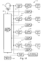
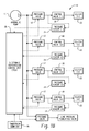
- Figures 1A and 1 B are block diagrams of a closed loop transmission control system in which a package according to one embodiment of the invention can be used;
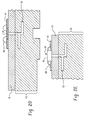
- Figures 2A through 2E illustrate section views of various embodiments of a transducer incorporated in the inventive package;
- Figures 3A and 3B are representative top and bottom views of a package according to one embodiment of the invention;
- Figure 4 is a representative top perspective view of a sub-package to be used in a package according to another embodiment of the invention; and
- Figure 5 is a representative top perspective view of a package incorporating the sub-package shown in Figure 4.
- Figures 1A and 1B are representative block diagrams illustrating a closed-loop
pressure control system 10 for a vehicle transmission in which a pressure transducer package according to the invention can be used. Note that these figures are for illustrative purposes only to describe one possible application for the inventive package and are not meant to limit the scope of the invention in any way. Those of ordinary skill in the art will - The
system 10 may include a plurality of solenoid operatedvalves 12 supplied with pressurized hydraulic fluid from apump 11, which may be driven by a transmission input shaft. Eachvalve 12 supplies pressurized fluid along a conduit to ahydraulic control valve 18, and the output of eachhydraulic control valve 18 is applied through a conduit to a hydraulically actuatedclutch 22, as for example, a band clutch or plate clutch, for controlling torque transmission upon a speed (gear) change. - The pressure supplied to each clutch (Figure 1A) or to each control valve (Figure 1 B) along the clutch's respective conduit 20 is sensed by a
pressure transducer 24, which provides an electrical indication of the sensed pressure, as shown by a dashed line in Figures 1A and 1B, to an electronic transmission control unit (TCU) 26. The TCU 26 also receives an input in the form of a command pressure signal from apowertrain computer 28 that is programmed to provide the desired shift characteristics for the particular vehicle and engine-transmission combination. Thepressure transducers 24 may comprise any appropriate pressure sensor, such as a piezoelectric sensor. - In the inventive structure, one or
more pressure transducers 24 are incorporated into aunitary package 30 that can be easily incorporated into the transmission system 10 (e.g., by attachment to the TCU 26). Figures 2A through 2E are representative section views showing various embodiments of theinventive package 30 and ways they may be incorporated into a transmission manifold. Thepackage 30 may be encased in a plastic package housing 31 (Figures 3A though 5) for easy handling and protection. Although the illustrated examples show how thepackage 30 can be attached to aTCU 26, those of skill in the art will understand how thepackage 30 can be incorporated into other systems relying on fluid pressure control for operation. - As is known in the art, the TCU includes a
manifold 50 havinginternal pressure ports 52. In the illustrated embodiment, thepackage housing 31 sits on top of themanifold 50 and thetransducers 24 are disposed in thepackage 30, allowing thetransducers 24 to be oriented above themanifold 50. However, thepackage housing 31 may also be configured to sit on top of a TCU housing (not shown) or a plate (not shown) that is disposed on themanifold 50. - As shown in Figures 3A through 5, the
package 30 includes a plurality ofpressure transducers 24 coupled to thesubstrate 61, either directly or through a support, to form a single multiple-transducer package 30. - Referring to Figures 2A through 2C, the
package 30 may includesupports 62 integrated with a circuit card, a flex circuit, plated traces, or any other component acting as thesubstrate 61. Thesupports 52 may be made of glass or other insulating material. Thesupports 62 have their own associatedsupport ports 66 that correspond and align with thepressure ports 52 in themanifold 50 to form fluidic channels that allow fluid in thepressure ports 52 to reach thetransducers 24 when thepackage 30 is incorporated into thetransmission system 10. As a result, thetransducers 24 can generate an output based on the fluid pressure detected at its associatedpressure port 52. Alternatively, thesupports 62 are omitted so that thetransducers 24 are disposed directly on thesubstrate 61, without any other component acting as the interface between thetransducer 24 and thesubstrate 61. In this case, thepressure ports 52 communicate directly with thetransducers 24. - The
package 30 also includes aprocessor 70, such as a microprocessor or ASIC, disposed on the substrate 61 (Figures 3 through 5). In this example, awire bond 68 connects eachpressure transducer 24 to a corresponding electrical contact point 58 on thesubstrate 61 so that signals from thepressure transducer 24 can be routed elsewhere. Signals and current are routed between theTCU 26, thetransducers 24, and theprocessor 70 via any desired signal communication interface, such as a lead frame, stamped metal traces, flex-circuits, plated circuits, a wire harness, wireless means, etc. Note that in some embodiments, the same component (e.g., the lead frame, etc.) will act as both thesubstrate 61 and the signal communication interface. - Regardless of the
specific package configuration 30, the alignment between thepressure ports 52 and thetransducers 24 allows thepackage 30 to be retrofitted into any pre-existing transmission system, if desired. This allows thepackage 30 to be easily manufactured separately from theTCU 26 and be attached to theTCU 26 without having to reconfigure themanifold 50 to accommodate thepackage 30. - Figure 2A shows one embodiment where the
support 62 in thepackage 30 is embedded in thehousing 31 of theinventive package 30. To prevent fluid leakage, a sealing structure may be included around thepressure port 52. In the embodiment shown in Figure 2A, an O-ring 80 acts as the sealing structure and is wedged between the manifold 50 and the support 58 to fluidically seal thepressure port 52. Those of ordinary skill in the art will understand that other sealing structures, such as gasket material, may be used without departing from the scope of the invention. - An O-
ring 80 is also used in the embodiment of Figure 2B, but in this case the O-ring 80 is wedged into a depression 72 in themanifold 50. Note that in Figure 2B, thesupport 62 and the circuit card 64 are disposed on top of thepackage housing 31 rather than being embedded in it. Like the embodiment shown in Figure 2A, the arrangement of thetransducers 24 on the circuit card 64 in this embodiment can be adjusted to correspond with the configuration of thepressure ports 52 in themanifold 50. - Figure 2C shows an alternative sealing structure that does not require a separate O-ring. Instead, the support 58 has a tapered (e.g. frusto-conical)
extension 82 or similar integral structure. When the support 58 is embedded into thepackage housing 31, theextension 82 extends out of thepackage 30 below thehousing 31 into the manifold 50 to form a press-fit, fluid-tight seal around thepressure port 52. Like the embodiment of Figure 2B, this embodiment allows thepackage 30 to be manufactured separately from the rest ofsystem 10 and attached to the manifold 50 in a modular fashion. - Although Figures 2A through 2C show the
transducers 24 disposed above the top surface of thesubstrate 61, those of ordinary skill in the art will understand that thetransducers 24 may be disposed on or below the bottom surface of thesubstrate 61 as well without departing from the scope of the invention. - Figure 2D shows an alternative structure wherein the
pressure transducer 24 is disposed on thesubstrate 61 so that thetransducer 24 can be bonded or mechanically fastened so that it communicates directly with the pressure ports 52 (e.g., bonded or mechanically fastened to the housing 31). This may be accomplished by, for example, placing thetransducer 24 on an underside of thesubstrate 61 or embedding thetransducer 24 in thesubstrate 61 to leave thetransducer 24 exposed for interfacing with thepressure port 52. The wire bonds 68 are then connected via thewire bonds 68 to the communication interface, such as a flex circuit or traces plated directly on theTCU 26, or on an insulated interface. In this embodiment, thetransducer 24 communicates directly with thepressure port 52. Note that although the embodiment in Figure 2D shows thetransducer 24 incorporated in thesubstrate 61, the package may also allow direct contact between thetransducer 24 and thepressure port 52 by mounting thetransducer 24 to the underside of thesubstrate 61. - Figure 2E shows an alternative structure where the
pressure transducer 24 is disposed inside anindividual transducer housing 70. Thehousing 70 may then directly bonded to the TCU or a subcarrier (e.g., the package housing 31) and thewire bonds 68 are bonded out to a communication interface on the TCU or on an insulated interface. - Note that although Figures 2D and 2E do not show a sealing structure, those of ordinary skill in the art will understand that any of the sealing structures shown in Figures 2A through 2C may be incorporated into the embodiments of Figures 2D and 2E without departing from the scope of the invention.
- Regardless of the specific orientation of the
transducers 24, wire bonds or package leads 68 route signals generated by the transducer(s) 24 to a communication interface (not shown) on thesubstrate 61, such as a flex-circuit or plated traces, which in turn route the signals to theprocessor 70 that processes the transducer signals. - By configuring the
package 30 so that thetransducers 24 are together in a single device itself rather than discrete components scattered throughout thetransmission system 10, the invention shortens the signal path between the manifold 50 and thetransducers 24 and between thetransducers 24 and theprocessor 70 reducing the complexity of the overall transmission control system and making it less sensitive to noise. - If the
inventive package 30 is incorporated in aTCU 26, thepackage 30 may use a pre-existing processor in theTCU 26 to process the transducer signals, if desired. Also, thetransducers 24 may be configured in any desired fashion with thepackage 30. - Figures 3A through 5 show possible transducer arrangements in the
package 30. Note that invention is not limited to these configurations and that other configurations are possible without departing from the scope of the invention. Thepackage 30 can be built using any of the structures shown in Figures 2A through 2E. As noted above, thepackage 30 is manufactured separately from the manifold 50 and can be connected to the manifold 50 by a harness, lead frame, or any other connector. - Figures 3A and 3B illustrate a package configuration where the
transducers 24 are arranged roughly in a circular or hexagonal shape on theirrespective substrates 61. Thetransducers 24 and theprocessor 70 are housed in thepackage housing 31.Optional dams 73 or filler material may be included in thepackage 30 to stabilize thetransducers 24 andprocessor 70 to prevent them from becoming jarred loose over time. Thepackage housing 30 may also include abolt hole 74 to allow thepackage 30 to be attached easily to the manifold 50 with a single bolt. - Because the
transducers 24 andprocessor 70 are grouped together in asingle package 30, only four connection lines 90 (i.e., data, clock, power and ground) are needed to connect thetransducers 24 to theTCU 26. This reduces the overall length of the traces between theprocessor 70 and thetransducers 24 and reduces the total number of connections to theTCU 26, making the overall pressure sensing system more noise-resistant. Further, thepackage 30 acts as a modular component that can be attached to any manifold without reconfiguration of the manifold itself. - Figures 4 and 5 illustrate another embodiment where the
package 30 includes one ormore sub-packages 100. Figure 4 shows one embodiment of the sub-package 100. The sub-package 100 includes two or more of thetransducers 24 and its own associatedsub-package lines 102 andsub-package housing 104. As shown in Figure 5, two or more of the sub-packages 100 are disposed in thepackage housing 31 to form thecomplete package 30. Thesub-package lines 102 are coupled to package traces 106, which are in turn connected to the connection lines 90. In the example shown in Figure 5, each sub-package 100 has its own data and clock connection lines, and the two sub-packages share power and ground lines. In this example, thepackage housing 31 includes twobolt holes 74 for attaching thepackage 30 to the manifold. - Note that the sub-packages 100 may be calibrated before they are assembled into the
package 30. This makes it possible for different entities to manufacture the sub-package 100 and thefinished package 100. - The arrangements described above are simply illustrative examples of possible embodiments. Those of ordinary skill in the art will understand that the package can have different configurations without departing from the scope of the invention. Further, although the above examples focus on a transmission manifold, those of ordinary skill in the art will see that the inventive package can be used in any fluid pressure sensing system.
- By incorporating one or more transducers and a processor into a single package, the invention provides fluid pressure monitoring and control capabilities without requiring reconfiguration of the entire manifold. Instead, fluid in the manifold can simply be redirected to the inventive package using, for example, an adapter plate that reroutes fluid to the transducers. This allows the package to add pressure sensing capabilities to any fluid system, regardless of the manifold configuration.
- Although the invention has hereinabove been described with respect to the illustrated embodiments, it will be understood that the invention is capable of modification and variation and is limited only by the following claims.
Claims (29)
- A pressure transducer package (30) that is attachable to a manifold (50) having at least one pressure port (52), the package comprising:at least one transducer (24), each transducer arranged to correspond with one pressure port, wherein each transducer generates a signal corresponding to fluid pressure in the pressure port;a processor (70) that receives the signals from said at least one transducer; anda housing (31) that houses said at least one transducer and the processor.
- The package of claim 1, further comprising a substrate (61) that supports at least one of the transducers.
- The package of claim 2, wherein the substrate is embedded in the housing.
- The package of claim 2, wherein the substrate is disposed on the housing.
- The package of claim 2, wherein the substrate one is selected from the group consisting of a circuit card, a flex-circuit, and plated traces.
- The package of claim 2, further comprising at least one support (62) coupling said at least one transducer to the substrate.
- The package of claim 6, wherein said at least one support is made from an insulating material.
- The package of claim 6, wherein said at least one support has a support port (66), wherein the support port couples with said at least one pressure port to form at least one fluid channel that can carry fluid to one of the transducers.
- The package of claim 2, wherein said at least one transducer is attached directly to the substrate.
- The package of claim 1, wherein said at least one transducer is disposed so that the transducers can directly contact the pressure ports when attached to the manifold.
- The package of claim 1, further comprising a transducer housing (70) surrounding at least one of said plurality of transducers.
- The package of claim 1, wherein said at least one transducer comprises at least two transducers that are arranged in at least two sub-packages (100), each sub-package having at least one transducer and a sub-package housing (104).
- A package (30) for attachment to a manifold (50) having a plurality of pressure ports (52), the package comprising:a plurality of transducers (24), each transducer arranged to correspond with one of the plurality of pressure ports in the manifold and generating a signal corresponding to fluid pressure in one of the plurality of pressure ports;a processor (70) that receives the signals from the plurality of transducers;a substrate (61) that supports at least one of the plurality of transducers;a signal communication interface that routes signals between the plurality of transducers and the processor;at least one connection line (90) for coupling the package to an external system; anda housing (31) that houses the plurality of transducers, the processor and the signal communication interface.
- The package of claim 13, wherein the substrate is one selected from the group consisting of a circuit card, a flex-circuit, and plated traces.
- The package of claim 13, wherein the signal communication interface is one selected from the group consisting of a lead frame, stamped metal traces, flex-circuits, plated circuits, a wire harness, and a wireless means.
- The package of claim 13, wherein the substrate and the signal communication interface are the same component.
- The package of claim 13, further comprising at least one support (62) connecting at least one of the plurality of transducers to the substrate.
- The package of claim 17, wherein said at least one support has a support port (66), wherein the support ports in the package couple with the plurality of pressure ports to form a plurality of fluid channels that can carry fluid to the plurality of transducers.
- The package of claim 13, wherein the plurality of transducers are disposed so that the transducers can directly contact the pressure ports when attached to the transmission manifold.
- The package of claim 13, wherein the plurality of transducers are attached directly to the substrate.
- The package of claim 13, further comprising a transducer housing (70) surrounding at least one of said plurality of transducers.
- The package of claim 13, wherein the plurality of transducers are arranged in at least two sub-packages (100), each sub-package having at least one of said plurality of transducers and a sub-package housing (104).
- The package of claim 22, wherein each sub-package has at least one sub-package line (102), and wherein said at least one sub-package line is connected to said at least one connection line through at least one package trace disposed in the package housing.
- A method of manufacturing a package (30) for attachment to a manifold (50) having a plurality of pressure ports (52), comprising:disposing a plurality of pressure transducers (24) in a housing, each transducer arranged to correspond with one of the plurality of pressure ports in the manifold; anddisposing a processor (70) that receives the signals from the plurality of transducers into the housing; andincorporating into the housing (31) a signal communication interface that routes signals between the plurality of transducers and the processor.
- The method of claim 24, wherein the plurality of transducers (24) and the processor are disposed in at least one sub-package (100), each sub-package containing at least one of said plurality of transducers, and wherein the step of disposing the plurality of pressure transducers comprises disposing said at least one sub-package in the housing.
- The method of claim 25, further comprising connecting at least one sub-package line (102) to at least one package trace (106) in the package, wherein said at least one package trace is connected to at least one connection line (90) that connects the package to an external system.
- The method of claim 24, further comprising coupling the plurality of pressure transducers onto at least one substrate (61) in the housing.
- The method of claim 27, wherein the step of coupling the plurality of pressure transducers comprises disposing said plurality of transducers directly onto said at least one substrate.
- The method of claim 27, wherein the step of coupling the plurality of pressure transducers comprises:disposing a plurality of supports in the housing; andconnecting the plurality of transducers to the plurality of supports.
Applications Claiming Priority (1)
| Application Number | Priority Date | Filing Date | Title |
|---|---|---|---|
| US11/235,614 US7383735B2 (en) | 2005-09-26 | 2005-09-26 | Pressure transducer package for a manifold |
Publications (2)
| Publication Number | Publication Date |
|---|---|
| EP1767916A2 true EP1767916A2 (en) | 2007-03-28 |
| EP1767916A3 EP1767916A3 (en) | 2014-04-09 |
Family
ID=37547529
Family Applications (1)
| Application Number | Title | Priority Date | Filing Date |
|---|---|---|---|
| EP06019995.7A Withdrawn EP1767916A3 (en) | 2005-09-26 | 2006-09-25 | Pressure transducer package for a manifold |
Country Status (3)
| Country | Link |
|---|---|
| US (1) | US7383735B2 (en) |
| EP (1) | EP1767916A3 (en) |
| JP (1) | JP2007093604A (en) |
Cited By (1)
| Publication number | Priority date | Publication date | Assignee | Title |
|---|---|---|---|---|
| EP3719470A2 (en) * | 2019-04-05 | 2020-10-07 | Honeywell International Inc. | Pressure sensor with multiple pressure sensing elements |
Families Citing this family (2)
| Publication number | Priority date | Publication date | Assignee | Title |
|---|---|---|---|---|
| EP2647885B1 (en) * | 2011-03-31 | 2016-04-27 | Aisin AW Co., Ltd. | Transmission control device, and method for determining generation of braking torque in transmission |
| JP6701931B2 (en) * | 2016-05-02 | 2020-05-27 | 日本電産トーソク株式会社 | Oil pressure sensor mounting structure |
Citations (2)
| Publication number | Priority date | Publication date | Assignee | Title |
|---|---|---|---|---|
| US5803123A (en) * | 1994-06-03 | 1998-09-08 | Keystone International Holdings Corp. | Mounting system for pressure transmitters |
| WO2000030909A1 (en) * | 1998-11-25 | 2000-06-02 | Kelsey-Hayes Company | Structure for mounting a cluster of pressure sensors upon an electro-hydraulic brake system control unit |
Family Cites Families (14)
| Publication number | Priority date | Publication date | Assignee | Title |
|---|---|---|---|---|
| JPH10197381A (en) * | 1997-01-10 | 1998-07-31 | Nippon Aleph Corp | Sensor device |
| US6220101B1 (en) * | 1998-02-03 | 2001-04-24 | Ssi Technologies, Inc. | Apparatus for measuring multiple pressures |
| EP1068120B1 (en) * | 1998-03-31 | 2002-07-03 | Continental Teves AG & Co. oHG | Pressure sensor assembly |
| DE19834212A1 (en) * | 1998-07-29 | 2000-02-10 | Siemens Ag | Control device in a motor vehicle and pressure sensor used by this |
| EP1108163B1 (en) * | 1998-08-24 | 2002-03-06 | Siemens Aktiengesellschaft | Control device in a motor vehicle |
| JP3432780B2 (en) * | 2000-02-22 | 2003-08-04 | 株式会社日立製作所 | Semiconductor pressure sensor |
| US6883874B2 (en) * | 2000-09-14 | 2005-04-26 | New York Air Brake Corporation | Pressure sensor module |
| US20020038975A1 (en) * | 2000-09-15 | 2002-04-04 | Mccurdy William B. | Pressure sensor module |
| US6687642B2 (en) * | 2001-01-26 | 2004-02-03 | Texas Instruments Incorporated | Condition responsive sense system and method |
| JP2003254849A (en) * | 2002-02-28 | 2003-09-10 | Sunx Ltd | Pressure detector and pressure sensor |
| US20040118466A1 (en) * | 2002-12-19 | 2004-06-24 | Eaton Corporation | Electro-hydraulic manifold assembly and pressure sensor therefor |
| US6807472B2 (en) * | 2002-12-23 | 2004-10-19 | Eaton Corporation | Closed loop control of shifting clutch actuators in an automatic speed change transmission |
| US6929031B2 (en) * | 2003-03-28 | 2005-08-16 | Eaton Corporation | Electro-hydraulic manifold assembly with lead frame mounted pressure sensors |
| US20050070205A1 (en) * | 2003-09-30 | 2005-03-31 | Speedfam-Ipec Corporation | Integrated pressure control system for workpiece carrier |
-
2005
- 2005-09-26 US US11/235,614 patent/US7383735B2/en not_active Expired - Fee Related
-
2006
- 2006-09-25 EP EP06019995.7A patent/EP1767916A3/en not_active Withdrawn
- 2006-09-26 JP JP2006260570A patent/JP2007093604A/en active Pending
Patent Citations (2)
| Publication number | Priority date | Publication date | Assignee | Title |
|---|---|---|---|---|
| US5803123A (en) * | 1994-06-03 | 1998-09-08 | Keystone International Holdings Corp. | Mounting system for pressure transmitters |
| WO2000030909A1 (en) * | 1998-11-25 | 2000-06-02 | Kelsey-Hayes Company | Structure for mounting a cluster of pressure sensors upon an electro-hydraulic brake system control unit |
Cited By (2)
| Publication number | Priority date | Publication date | Assignee | Title |
|---|---|---|---|---|
| EP3719470A2 (en) * | 2019-04-05 | 2020-10-07 | Honeywell International Inc. | Pressure sensor with multiple pressure sensing elements |
| US11650119B2 (en) | 2019-04-05 | 2023-05-16 | Honeywell International Inc. | Pressure sensor with multiple pressure sensing elements |
Also Published As
| Publication number | Publication date |
|---|---|
| JP2007093604A (en) | 2007-04-12 |
| US20070068268A1 (en) | 2007-03-29 |
| US7383735B2 (en) | 2008-06-10 |
| EP1767916A3 (en) | 2014-04-09 |
Similar Documents
| Publication | Publication Date | Title |
|---|---|---|
| EP1462681B1 (en) | Electro-hydraulic manifold assembly with lead frame mounted pressure sensors | |
| US7908734B2 (en) | Manifold assembly having a centralized pressure sensing package | |
| US20090299583A1 (en) | Method and apparatus for detecting and compensating for pressure transducer errors | |
| EP1508731B1 (en) | Electric fluid servo valve and method of making same | |
| JP2008528897A (en) | Electromagnetic pressure control valve device with built-in pressure sensor | |
| US7486996B2 (en) | Transmission control unit having pressure transducer package | |
| EP1437532A2 (en) | Electro-hydraulic manifold assembly and pressure sensor therefor | |
| US7909721B2 (en) | Fluid pressure control assembly | |
| US7383735B2 (en) | Pressure transducer package for a manifold | |
| US6544138B2 (en) | Electro-hydraulic module for automatic transmission control | |
| US20060032541A1 (en) | Electro-hydraulic manifold assembly with mounted pressure sensors | |
| WO2003016753A1 (en) | Electro-hydraulic module for transmission control | |
| JPH05196061A (en) | Actuator controller | |
| WO2002066868A1 (en) | Mechatronics pressure sensor and contact |
Legal Events
| Date | Code | Title | Description |
|---|---|---|---|
| PUAI | Public reference made under article 153(3) epc to a published international application that has entered the european phase |
Free format text: ORIGINAL CODE: 0009012 |
|
| AK | Designated contracting states |
Kind code of ref document: A2 Designated state(s): AT BE BG CH CY CZ DE DK EE ES FI FR GB GR HU IE IS IT LI LT LU LV MC NL PL PT RO SE SI SK TR |
|
| AX | Request for extension of the european patent |
Extension state: AL BA HR MK YU |
|
| PUAL | Search report despatched |
Free format text: ORIGINAL CODE: 0009013 |
|
| AK | Designated contracting states |
Kind code of ref document: A3 Designated state(s): AT BE BG CH CY CZ DE DK EE ES FI FR GB GR HU IE IS IT LI LT LU LV MC NL PL PT RO SE SI SK TR |
|
| AX | Request for extension of the european patent |
Extension state: AL BA HR MK RS |
|
| RIC1 | Information provided on ipc code assigned before grant |
Ipc: G01L 19/00 20060101ALI20140228BHEP Ipc: F16H 59/68 20060101ALI20140228BHEP Ipc: G01L 9/00 20060101ALI20140228BHEP Ipc: G01L 15/00 20060101AFI20140228BHEP Ipc: G01L 19/14 20060101ALI20140228BHEP Ipc: G01L 23/24 20060101ALI20140228BHEP |
|
| 17P | Request for examination filed |
Effective date: 20140523 |
|
| RBV | Designated contracting states (corrected) |
Designated state(s): DE FR GB IT PL SE |
|
| AKX | Designation fees paid |
Designated state(s): DE FR GB IT PL SE |
|
| AXX | Extension fees paid |
Extension state: HR Extension state: RS Extension state: BA Extension state: AL Extension state: MK |
|
| 17Q | First examination report despatched |
Effective date: 20160603 |
|
| GRAP | Despatch of communication of intention to grant a patent |
Free format text: ORIGINAL CODE: EPIDOSNIGR1 |
|
| STAA | Information on the status of an ep patent application or granted ep patent |
Free format text: STATUS: GRANT OF PATENT IS INTENDED |
|
| INTG | Intention to grant announced |
Effective date: 20170222 |
|
| STAA | Information on the status of an ep patent application or granted ep patent |
Free format text: STATUS: THE APPLICATION IS DEEMED TO BE WITHDRAWN |
|
| 18D | Application deemed to be withdrawn |
Effective date: 20170705 |