EP1767893A1 - Missile guidance system - Google Patents
Missile guidance system Download PDFInfo
- Publication number
- EP1767893A1 EP1767893A1 EP05108819A EP05108819A EP1767893A1 EP 1767893 A1 EP1767893 A1 EP 1767893A1 EP 05108819 A EP05108819 A EP 05108819A EP 05108819 A EP05108819 A EP 05108819A EP 1767893 A1 EP1767893 A1 EP 1767893A1
- Authority
- EP
- European Patent Office
- Prior art keywords
- missile
- ref
- des
- target
- flight direction
- Prior art date
- Legal status (The legal status is an assumption and is not a legal conclusion. Google has not performed a legal analysis and makes no representation as to the accuracy of the status listed.)
- Granted
Links
Images

Classifications
-
- F—MECHANICAL ENGINEERING; LIGHTING; HEATING; WEAPONS; BLASTING
- F41—WEAPONS
- F41G—WEAPON SIGHTS; AIMING
- F41G7/00—Direction control systems for self-propelled missiles
- F41G7/20—Direction control systems for self-propelled missiles based on continuous observation of target position
- F41G7/22—Homing guidance systems
Definitions
- the present invention refers to a method and a system for guiding a missile, and also to a missile provided with such a system.
- it refers to such guidance systems for missiles using passive target seeker, where the missile is devised not to hit the target dead on, but to pass by at a predetermined distance.
- One example comprises an antitank missile travelling approximately horizontally and provided with a shaped charge devised to hit at an angle downwards/forwards. Said missile should pass approximately one meter over the tank to enable the shaped charge to achieve good effect at the tank. It should be mentioned that most conventional tanks usually are well protected against direct hits from the front, side and behind.
- the missiles "NLAW” and “Bill” are examples of missiles using such a method, although they are not utilising target seeking mechanisms.
- Another example concerns attacks using a ground target missile, where the target seeker is not able to see the target, but where it has been possible to determine the target position in relation to one or more other objects that can be seen by the target seeker.
- US 5,932,833 discloses a fly over homing guidance system for terminal homing missile guidance which comprises a fire and forget missile guidance method wherein on board target sensing tracks the target and guides the missile to the target, but instead of being guided to a direct impact as is conventionally done, the missile is guided towards a precise distance over the top of the target, intentionally avoiding impact.
- Said missile guidance system comprises a gamma-ref calculation unit capable of calculating a reference value of a vertical flight direction angle which, if used to adjust a current vertical flight direction angle ⁇ ref of said missile, would cause the missile to pass the target at a desired passage height (h des ).
- Said gamma-ref calculation unit calculates the reference value of the vertical flight direction angle ( ⁇ ref ) based on the following parameters:
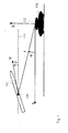
- Fig. 1 shows a schematic illustration defining directions, distances and angles according to a preferred embodiment of the present invention.
- An antitank missile 101 is travelling with a velocity V.
- the velocity vector forms a vertical flight direction angle ⁇ with the horizontal plane 110.
- the antitank missile 101 has a centre of gravity 103.
- a target total distance r between the centre of gravity 103 of the missile 101 represents the line of sight between said centre of gravity and a top surface 122 of a target 120.
- the target distance r forms an elevation angle ⁇ with a horizontal x-axis.
- a target vertical distance from the centre of gravity 103 of the missile 101 to the top surface 122 of the target 120 is designated h.
- the missile 101 is provided with an inertial navigation system.
- the missile 101 is also provided with a target seeking system.
- the target seeking system could be any type of present or future passive or active target seeking systems based on, but not restricted to, one or more of the following principles: laser, infra-red, radio, radar, heat and/or optical.
- laser, infra-red, radio, radar, heat and/or optical With the aid of the target seeking system information about the direction, or the direction and the distance to the target 120, a method and a system according to an embodiment of the present invention easily calculates the necessary values of the elevation ⁇ and the line-of-sight rotation ⁇ .
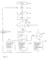
- Fig. 2 A is a flowchart of a method of a missile guidance system according to a preferred embodiment of the present invention. Said method comprises the following steps:
- this comprises the following step:
- Fig. 2 B is a flowchart of part of an alternative preferred embodiment of the present invention.
- the case where the desired height h des and the line-of-sight rotation ⁇ have different signs is handled separately, This case is handled in a method of a further embodiment of the present invention comprising the following steps:
- the function for determining the reference value of the vertical flight direction angle ⁇ ref comprises the following variables: the desired passage height h des , the line-of-sight rotation ⁇ , the velocity V and the elevation angle ⁇ .
- the reference value of the vertical flight direction angle ⁇ ref is formed as, or derived from, the difference between the square root of the desired height h des multiplied with the line-of-sight rotation ⁇ divided by the velocity V and the elevation angle ⁇ .
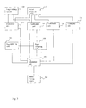
- Fig. 3 shows a system overview of a missile guidance system according to a preferred embodiment of the invention.
- a target seeking system 305 is connected to an elevation angle ⁇ estimator unit 315. Said target seeking system 305 is also connected to a line-of-sight rotation ⁇ estimator unit 320.
- An inertial navigation system 310 is connected to said elevation angle ⁇ estimator unit 315, to said line-of-sight rotation estimator unit 320, and also to a velocity V estimator unit 325, and a vertical flight direction angle ⁇ estimator unit 330.
- the inertial navigation system 310, the target seeking system 305, and the missile steering system 360 should be viewed at as conventional ditos.
- the navigation system 310 is preferably of a strapped-down type as explained in e.g. D.H. Titterton and J. L. Weston "Strapdown inertial navigation technology" ISBN 086341 260 2 .
- the estimator units 315, 320, 325, 330 may also be part of the target seeking system 305 or the inertial navigation system depending on selected level of integration.
- Said elevation angle estimator unit 315 is further connected to a gamma-ref calculation unit 350.
- Said line-of-sight rotation estimator unit 320 is connected to a sign comparing unit 340, and also to said gamma-ref calculation unit 350.
- Said velocity estimator unit 325 is further connected to said gamma-ref calculation unit 350.
- Said vertical flight direction angle estimator unit 330 is further connected to a missile steering system 360.
- Said sign comparing unit 340 is connected to a desired passage height obtaining unit 345, and to the gamma-ref calculation unit 350.
- Said gamma-ref calculation unit 350 is further connected to the missile steering system 360.
- the target seeking system 305 measures the direction to the target and provides values representative of this direction to the elevation angle estimator unit 315, and to the line-of-sight estimator unit 320.
- the elevation angle estimator unit 315 receives values from the target seeking system representative of the direction to the target.
- Said elevation angle estimator unit makes an estimate of the current elevation angle ⁇ based on the values from the target seeking system and values from the inertial navigation system 310, representative of the missiles own flight parameters, such as altitude angles and translational and rotational velocities.
- the line-of-sight rotation estimator unit 320 estimates in a similar way the line-of-sight rotation ⁇ based on values from the target seeking system 305 and the inertial navigation system 310.
- the velocity estimator unit 325 estimates the velocity based on values from the inertial navigation system 310, representative of the velocity V.
- the velocity estimator unit 325 is also connected to the target seeking system 305, and the velocity is estimated based on both values from the inertial navigation system 310 and from the target seeking system 305.
- the gamma estimator unit 330 receives values from the inertial navigation system and estimates a vertical flight direction angle ⁇ . Said gamma estimator unit 330 communicates said estimated vertical flight direction angle ⁇ to the missile steering system 360.
- the desired height obtaining unit 345 obtains the desired height. Said obtaining can be effected by manual setting or automatic setting by a computer program, or another suitable method.
- the value representing the desired passing height h des is communicated to the sign comparing unit.
- the sign comparing unit 340 compares the signs of the designated passage height and the line-of-sight rotation ⁇ .
- the result is communicated to the gamma-ref calculation unit 350, which calculates a reference value for the vertical flight direction angle ⁇ ref according to the method explained above.
- the reference value ⁇ ref is then communicated to the missile steering system 360, which makes the necessary adjustments of the missile ailerons, control surfaces, or other means for adjusting the course of the missile to get the vertical flight direction angle ⁇ closer to the reference value ⁇ ref .
- missile guidance system also comprises a horizontal guidance function. This is however not part of the invention and is not described here.
Landscapes
- Engineering & Computer Science (AREA)
- Chemical & Material Sciences (AREA)
- Combustion & Propulsion (AREA)
- General Engineering & Computer Science (AREA)
- Aiming, Guidance, Guns With A Light Source, Armor, Camouflage, And Targets (AREA)
Abstract
Description
- The present invention refers to a method and a system for guiding a missile, and also to a missile provided with such a system. In particular, it refers to such guidance systems for missiles using passive target seeker, where the missile is devised not to hit the target dead on, but to pass by at a predetermined distance.
- When using missile systems it is sometimes desirable to let the missile miss the target with a certain distance. One example comprises an antitank missile travelling approximately horizontally and provided with a shaped charge devised to hit at an angle downwards/forwards. Said missile should pass approximately one meter over the tank to enable the shaped charge to achieve good effect at the tank. It should be mentioned that most conventional tanks usually are well protected against direct hits from the front, side and behind. The missiles "NLAW" and "Bill" are examples of missiles using such a method, although they are not utilising target seeking mechanisms.
- Another example concerns attacks using a ground target missile, where the target seeker is not able to see the target, but where it has been possible to determine the target position in relation to one or more other objects that can be seen by the target seeker.
- Most known missile systems for antitank warfare use missiles that approach the target from above. There seems to be few if any known systems of today that combine the benefits of a target seeker, a horizontally flying missile having a shaped charge devised to hit downwards, with means for steering the missile in such a way that it passes a predetermined distance above the target.
-
US 5,932,833 discloses a fly over homing guidance system for terminal homing missile guidance which comprises a fire and forget missile guidance method wherein on board target sensing tracks the target and guides the missile to the target, but instead of being guided to a direct impact as is conventionally done, the missile is guided towards a precise distance over the top of the target, intentionally avoiding impact. - The use of target seeking and inertial navigation system data in order to accomplish a direct hit is well known in the art. The use of the same information to accomplish that the missile "misses" the target with an appropriate distance is less known.
- It is a purpose of the present invention to provide a missile guidance system for use in a missile, where said system is capable of guiding said missile to pass a predetermined distance above a target.
- Said missile guidance system comprises a gamma-ref calculation unit capable of calculating a reference value of a vertical flight direction angle which, if used to adjust a current vertical flight direction angle γref of said missile, would cause the missile to pass the target at a desired passage height (hdes).
- Said gamma-ref calculation unit calculates the reference value of the vertical flight direction angle (γref) based on the following parameters:
- an elevation angle (σ)
- a desired passage height (hdes)
- a line-of-sight rotation (σ̇)
- a missile velocity (V).
- In a preferred embodiment said reference value is calculated as

- Preferred embodiments of the present invention is described with reference to the accompanying drawings, in which:
- fig. 1 is a schematic illustration defining directions, distances and angles of a missile guidance system according to a preferred embodiment of the invention,
- fig. 2 is a flowchart of a method of a missile guidance systems according to a preferred embodiment of the invention,
- fig. 3 shows a system overview of a missile guidance system according to a preferred embodiment of the invention.
- Fig. 1 shows a schematic illustration defining directions, distances and angles according to a preferred embodiment of the present invention. An
antitank missile 101 is travelling with a velocity V. The velocity vector forms a vertical flight direction angle γ with thehorizontal plane 110. Theantitank missile 101 has a centre ofgravity 103. A target total distance r between the centre ofgravity 103 of themissile 101 represents the line of sight between said centre of gravity and atop surface 122 of atarget 120. The target distance r forms an elevation angle σ with a horizontal x-axis. A target vertical distance from the centre ofgravity 103 of themissile 101 to thetop surface 122 of thetarget 120 is designated h. - As can be derived from fig. 1, the travelling path of the missile aims such that if all parameters are left unchanged, the missile would pass over the target at a target vertical distance h, where h can be estimated from the following formula

- Assuming the target total distance r is greater than the target vertical distance h, the target vertical distance h can be approximated with the formula

where h' designates an estimated target vertical passing distance, here also called estimated passage height. The time derivative of the elevation angle σ, also called the line-of-sight-rotation σ, fulfils the equation
- Using the equation (3) to solve the total (missile to) target distance r from the height expression (2) and utilising again that the elevation angle σ and the vertical flight direction angle γ are small, you arrive at:

- Assuming a straight flight path of the missile, the estimated passage height h' and the vertical flight direction angle γ will be constant, even though the velocity V, the elevation angle σ and the line-of-sight-rotation σ̇ may vary. From the expression (4) above, the inventors have chosen to form a reference value for the vertical flight direction angle γ according to the following expression

where "hdes" designates the desired passage height. This expression (5) will be referred to as "the law of guidance" in the following. - In order for the law of guidance to function properly, it is necessary to first check if the desired passage height hdes and the line-of-sight-rotation σ have the same sign. This since it is necessary to have a positive expression under the square root sign. If the signs are different, it is advisable to steer the missile such that the vertical flight direction angle γ becomes positive for desired passage heights hdes greater than zero, and such that the vertical flight direction angle γ becomes negative for desired passage heights hdes less than zero.
- The
missile 101 is provided with an inertial navigation system. Themissile 101 is also provided with a target seeking system. The target seeking system could be any type of present or future passive or active target seeking systems based on, but not restricted to, one or more of the following principles: laser, infra-red, radio, radar, heat and/or optical. With the aid of the target seeking system information about the direction, or the direction and the distance to thetarget 120, a method and a system according to an embodiment of the present invention easily calculates the necessary values of the elevation σ and the line-of-sight rotation σ̇. - Simulations have shown that the law of guidance (5) works best when the total target distance r is greater than approximately ten times the desired passage height hdes. One of the advantages with the law of guidance (5) is that when the missile is set for the correct desired passage height hdes, the reference value of the vertical flight direction angle γref will be constant, despite variations in the velocity V, the elevation angle σ and the line-of-sight rotation σ̇, i.e. corrections of the vertical flight direction angle γ will be minimised.
- The law of guidance (5) works less good according to performed simulations when the distance r is less than ten times the desired passage height. In practice this is not a problem since during the time left there is no time to perform any manoeuvre.
- Fig. 2 A is a flowchart of a method of a missile guidance system according to a preferred embodiment of the present invention. Said method comprises the following steps:
- Setting a desired passage height hdes, 205.
- Obtaining value of current elevation angle σ, 210.
- Obtaining value of current line-of-sight rotation σ̇, 212.
- Obtaining value of current velocity V, 215.
- Forming a reference value of the vertical flight direction angle γref as a function of desired passage height hdes, line-of-sight rotation σ̇, velocity V and elevation angle σ, 225.
- Steering the missile such that the vertical flight direction angle γ becomes closer to said reference angle γref, 230.
- For the method to be efficient, the inventors have realised that the case when the desired passage height and the line-of-sight rotation have different signs, has to be handled separately. In one embodiment this comprises the following step:
- Checking if the desired passage height hdes and the line-of-sight rotation σ̇ have the same sign, 220, and if so, performing the following steps:
- Checking if the desired height hdes is positive or negative, 240.
- If positive, steering the missile such that the vertical flight direction angle γ becomes slightly greater than zero, 245.
- If negative, steering the missile such that the vertical flight direction angle γ becomes slightly less than zero, 250.
- Fig. 2 B is a flowchart of part of an alternative preferred embodiment of the present invention. As described above, the case where the desired height hdes and the line-of-sight rotation σ̇ have different signs is handled separately, This case is handled in a method of a further embodiment of the present invention comprising the following steps:
- Checking if the desired passage height and the line-of-sight rotation have the same sign, 260.
- If they have, setting the reference value of the vertical flight direction angle γref to a value being a function of the desired passage height hdes, the line-of-sight rotation σ̇, the velocity V and the elevation angle σ, 210.
- If said variable does not have the same sign, and the desired passage height hdes is greater or equal to zero, setting the reference value of the vertical flight direction angle to a value greater than zero, 270.
- If said variable does not have the same sign, and the desired passage height hdes is less than zero, setting the reference value of the vertical flight direction angle to a value less than zero, 275.
- As can be seen from the above, the function for determining the reference value of the vertical flight direction angle γref comprises the following variables: the desired passage height hdes, the line-of-sight rotation σ̇, the velocity V and the elevation angle σ. In one embodiment, the reference value of the vertical flight direction angle γref is formed as, or derived from, the difference between the square root of the desired height hdes multiplied with the line-of-sight rotation σ̇ divided by the velocity V and the elevation angle σ.
- Fig. 3 shows a system overview of a missile guidance system according to a preferred embodiment of the invention.
- A
target seeking system 305 is connected to an elevation angleσ estimator unit 315. Saidtarget seeking system 305 is also connected to a line-of-sight rotationσ̇ estimator unit 320. - An
inertial navigation system 310 is connected to said elevation angleσ estimator unit 315, to said line-of-sightrotation estimator unit 320, and also to a velocityV estimator unit 325, and a vertical flight direction angleγ estimator unit 330. Theinertial navigation system 310, thetarget seeking system 305, and the missile steering system 360 should be viewed at as conventional ditos. Thenavigation system 310 is preferably of a strapped-down type as explained in e.g. D.H. Titterton and J. L. Weston "Strapdown inertial navigation technology" ISBN 086341 260 2. - The
estimator units target seeking system 305 or the inertial navigation system depending on selected level of integration. - Said elevation
angle estimator unit 315 is further connected to a gamma-ref calculation unit 350. - Said line-of-sight
rotation estimator unit 320 is connected to asign comparing unit 340, and also to said gamma-ref calculation unit 350. - Said
velocity estimator unit 325 is further connected to said gamma-ref calculation unit 350. - Said vertical flight direction
angle estimator unit 330 is further connected to a missile steering system 360. - Said
sign comparing unit 340 is connected to a desired passageheight obtaining unit 345, and to the gamma-ref calculation unit 350. - Said gamma-
ref calculation unit 350 is further connected to the missile steering system 360. - The
target seeking system 305 measures the direction to the target and provides values representative of this direction to the elevationangle estimator unit 315, and to the line-of-sight estimator unit 320. The elevationangle estimator unit 315 receives values from the target seeking system representative of the direction to the target. Said elevation angle estimator unit makes an estimate of the current elevation angle σ based on the values from the target seeking system and values from theinertial navigation system 310, representative of the missiles own flight parameters, such as altitude angles and translational and rotational velocities. - The line-of-sight
rotation estimator unit 320 estimates in a similar way the line-of-sight rotation σ̇ based on values from thetarget seeking system 305 and theinertial navigation system 310. Thevelocity estimator unit 325 estimates the velocity based on values from theinertial navigation system 310, representative of the velocity V. - In an alternative embodiment, the
velocity estimator unit 325 is also connected to thetarget seeking system 305, and the velocity is estimated based on both values from theinertial navigation system 310 and from thetarget seeking system 305. - The
gamma estimator unit 330 receives values from the inertial navigation system and estimates a vertical flight direction angle γ. Saidgamma estimator unit 330 communicates said estimated vertical flight direction angle γ to the missile steering system 360. - The desired
height obtaining unit 345 obtains the desired height. Said obtaining can be effected by manual setting or automatic setting by a computer program, or another suitable method. The value representing the desired passing height hdes is communicated to the sign comparing unit. Thesign comparing unit 340 compares the signs of the designated passage height and the line-of-sight rotation σ̇. The result is communicated to the gamma-ref calculation unit 350, which calculates a reference value for the vertical flight direction angle γref according to the method explained above. The reference value γref is then communicated to the missile steering system 360, which makes the necessary adjustments of the missile ailerons, control surfaces, or other means for adjusting the course of the missile to get the vertical flight direction angle γ closer to the reference value γref. Such course changes are obtained in one embodiment by steering in vertical direction according to the following expression:
where ac is the commanded acceleration and K is a constant. γref and γ as explained above. - In a further embodiment such course changes are obtained by steering in vertical direction according to the following expression:

where C is another constant and Vc is the commanded velocity. - It is understood the missile guidance system also comprises a horizontal guidance function. This is however not part of the invention and is not described here.
- The scope of the invention is only limited by the claims below.
Claims (10)
- A missile comprising a propulsion system, a target seeking system, an inertial navigation system, and a missile steering system, capable of adjusting a vertical flight direction angle (γ) of said missile in flight, characterised in that said missile comprises a missile guidance system, connected to said target seeking system, capable of guiding said missile, based on information from said target seeking system, to pass a predetermined distance (hdes) above a target (120).
- The missile of claim 1, where said missile guidance system comprises a gamma-ref calculation unit, capable of calculating a reference value of a vertical flight direction angle (γref) which, if used to adjust a current vertical flight direction angle (γ) of the missile, would cause the missile to pass the target (120) at a desired passage height (hdes).
- The missile of claim 2, where said gamma-ref calculation unit calculates the reference value of the vertical flight direction angle (γref) based on the following parameters:- an elevation angle (σ)- a desired passage height (hdes)- a line-of-sight rotation (σ̇)- a missile velocity (V).
- The missile of claim 3, where said parameters are used to calculate the reference value of the vertical flight direction angle (γref) according to the following expression

- A missile guidance system for use in a missile, characterised in that said system is capable of guiding said missile to pass a predetermined distance (hdes) above a target (120).
- The system of claim 5, where said system comprises a gamma-ref calculation unit capable of calculating a reference value of a vertical flight direction angle (γref) which, if used to adjust a current vertical flight direction angle (γ) of said missile, would cause the missile to pass the target (120) at a desired passage height (hdes).
- The system of claim 6, where said gamma-ref calculation unit calculates the reference value of the vertical flight direction angle (γref) based on the following parameters:- an elevation angle (σ),- a desired passage height (hdes),- a line-of-sight rotation (σ̇), and- a missile velocity (V).
- The system of claim 7, where said parameters are used to calculate the reference value of the vertical flight direction angle (γref) according to the following expression

- A method for guiding a missile towards a target, characterised in that said method comprises the following steps:- Setting a desired passage height (hdes), (205).- Obtaining value of current line-of-sight rotation (σ̇), (210).- Obtaining value of current velocity (V), (215).- Forming a reference value for a vertical flight direction angle (γref) as a function of desired passage height (hdes), line-of-sight rotation (σ), velocity (V) and elevation angle (σ), (225).- Steering the missile such that the vertical flight direction angle (γ) becomes closer to said reference angle (γref), (230).
- The method of claim 20, where said step of forming a reference value for the vertical flight direction angle (γref) comprises use of the expression

Priority Applications (4)
| Application Number | Priority Date | Filing Date | Title |
|---|---|---|---|
| EP05108819.3A EP1767893B1 (en) | 2005-09-23 | 2005-09-23 | Missile guidance system |
| ES05108819.3T ES2619597T3 (en) | 2005-09-23 | 2005-09-23 | Missile Guidance System |
| DK05108819.3T DK1767893T3 (en) | 2005-09-23 | 2005-09-23 | Missile Transfer System |
| US11/525,029 US7675011B2 (en) | 2005-09-23 | 2006-09-22 | Missile guidance system |
Applications Claiming Priority (1)
| Application Number | Priority Date | Filing Date | Title |
|---|---|---|---|
| EP05108819.3A EP1767893B1 (en) | 2005-09-23 | 2005-09-23 | Missile guidance system |
Publications (2)
| Publication Number | Publication Date |
|---|---|
| EP1767893A1 true EP1767893A1 (en) | 2007-03-28 |
| EP1767893B1 EP1767893B1 (en) | 2016-12-28 |
Family
ID=36177261
Family Applications (1)
| Application Number | Title | Priority Date | Filing Date |
|---|---|---|---|
| EP05108819.3A Expired - Lifetime EP1767893B1 (en) | 2005-09-23 | 2005-09-23 | Missile guidance system |
Country Status (4)
| Country | Link |
|---|---|
| US (1) | US7675011B2 (en) |
| EP (1) | EP1767893B1 (en) |
| DK (1) | DK1767893T3 (en) |
| ES (1) | ES2619597T3 (en) |
Cited By (2)
| Publication number | Priority date | Publication date | Assignee | Title |
|---|---|---|---|---|
| CN111442697A (en) * | 2020-02-07 | 2020-07-24 | 北京航空航天大学 | Over-emphasis guidance method and trajectory shaping guidance method based on pseudo-spectrum correction |
| DE102019103911A1 (en) * | 2019-02-15 | 2020-08-20 | Denel Dynamics, a division of Denel SOC Ltd | Method of combating air targets using guided missiles |
Families Citing this family (7)
| Publication number | Priority date | Publication date | Assignee | Title |
|---|---|---|---|---|
| WO2009013733A2 (en) * | 2007-07-20 | 2009-01-29 | Medingo Ltd. | Collapsible reservoir for use with a delivery device |
| US8563910B2 (en) * | 2009-06-05 | 2013-10-22 | The Charles Stark Draper Laboratory, Inc. | Systems and methods for targeting a projectile payload |
| US8513580B1 (en) * | 2012-06-26 | 2013-08-20 | The United States Of America As Represented By The Secretary Of The Navy | Targeting augmentation for short-range munitions |
| CN112631328B (en) * | 2020-12-12 | 2023-01-24 | 西北工业大学 | Multi-target cooperative terminal guidance law method |
| CN114329958B (en) * | 2021-12-27 | 2025-07-01 | 西安现代控制技术研究所 | A design method for mid-range guidance curve trajectory |
| US11913757B2 (en) * | 2022-01-18 | 2024-02-27 | Rosemount Aerospace Inc. | Constraining navigational drift in a munition |
| CN116107345B (en) * | 2022-12-13 | 2025-12-02 | 北京理工大学 | A cooperative guidance method for multiple aircraft |
Citations (7)
| Publication number | Priority date | Publication date | Assignee | Title |
|---|---|---|---|---|
| US4519315A (en) * | 1982-12-20 | 1985-05-28 | The United States Of America As Represented By The Secretary Of The Army | Fire and forget missiles system |
| EP0392086A2 (en) * | 1989-04-08 | 1990-10-17 | Rheinmetall GmbH | Fin stabilised projectile |
| EP0434474A1 (en) * | 1989-12-18 | 1991-06-26 | Societe D'etudes, De Realisations Et D'applications Techniques (S.E.R.A.T.) | Antitank missile having an angular momentum during its explosion, which takes place when flying over the target |
| FR2669722A1 (en) * | 1990-04-09 | 1992-05-29 | Serat | Weapons system acting by diving attack on the objective |
| US5755400A (en) * | 1980-10-02 | 1998-05-26 | Raytheon Company | Inertial instrumentation correction technique |
| US5932833A (en) * | 1997-03-03 | 1999-08-03 | The United States Of America As Represented By The Secretary Of The Army | Fly over homing guidance for fire and forget missile systems |
| WO2000000779A1 (en) * | 1998-06-26 | 2000-01-06 | Lfk-Lenkflugkörpersysteme Gmbh | Method for remote controlled combat of near-surface and/or surface targets |
Family Cites Families (9)
| Publication number | Priority date | Publication date | Assignee | Title |
|---|---|---|---|---|
| DE2650804C1 (en) * | 1976-11-06 | 1986-07-17 | Messerschmitt-Bölkow-Blohm GmbH, 8012 Ottobrunn | Installation on low-lying weapon carriers to combat ground targets |
| US4245560A (en) * | 1979-01-02 | 1981-01-20 | Raytheon Company | Antitank weapon system and elements therefor |
| DE3122252C1 (en) * | 1981-06-04 | 1982-11-04 | Diehl GmbH & Co, 8500 Nürnberg | Device for generating an end signal for overflight missiles |
| SE456036B (en) * | 1983-07-05 | 1988-08-29 | Bofors Ab | SET AND DEVICE TO CONTROL A CANNON EXTENDABLE PROJECTILE TO A TARGET |
| US4589610A (en) * | 1983-11-08 | 1986-05-20 | Westinghouse Electric Corp. | Guided missile subsystem |
| US4614317A (en) * | 1985-06-07 | 1986-09-30 | The Singer Company | Sensor for anti-tank projectile |
| FR2607585B1 (en) * | 1986-11-27 | 1993-04-09 | Matra | INDIRECT SHOOTING MINE OF ARMORED VEHICLE |
| US5455587A (en) * | 1993-07-26 | 1995-10-03 | Hughes Aircraft Company | Three dimensional imaging millimeter wave tracking and guidance system |
| US5932822A (en) * | 1997-06-27 | 1999-08-03 | Bernstein; Steven J. | Locking nut assembly for musical stringed instruments |
-
2005
- 2005-09-23 DK DK05108819.3T patent/DK1767893T3/en active
- 2005-09-23 ES ES05108819.3T patent/ES2619597T3/en not_active Expired - Lifetime
- 2005-09-23 EP EP05108819.3A patent/EP1767893B1/en not_active Expired - Lifetime
-
2006
- 2006-09-22 US US11/525,029 patent/US7675011B2/en active Active
Patent Citations (7)
| Publication number | Priority date | Publication date | Assignee | Title |
|---|---|---|---|---|
| US5755400A (en) * | 1980-10-02 | 1998-05-26 | Raytheon Company | Inertial instrumentation correction technique |
| US4519315A (en) * | 1982-12-20 | 1985-05-28 | The United States Of America As Represented By The Secretary Of The Army | Fire and forget missiles system |
| EP0392086A2 (en) * | 1989-04-08 | 1990-10-17 | Rheinmetall GmbH | Fin stabilised projectile |
| EP0434474A1 (en) * | 1989-12-18 | 1991-06-26 | Societe D'etudes, De Realisations Et D'applications Techniques (S.E.R.A.T.) | Antitank missile having an angular momentum during its explosion, which takes place when flying over the target |
| FR2669722A1 (en) * | 1990-04-09 | 1992-05-29 | Serat | Weapons system acting by diving attack on the objective |
| US5932833A (en) * | 1997-03-03 | 1999-08-03 | The United States Of America As Represented By The Secretary Of The Army | Fly over homing guidance for fire and forget missile systems |
| WO2000000779A1 (en) * | 1998-06-26 | 2000-01-06 | Lfk-Lenkflugkörpersysteme Gmbh | Method for remote controlled combat of near-surface and/or surface targets |
Cited By (3)
| Publication number | Priority date | Publication date | Assignee | Title |
|---|---|---|---|---|
| DE102019103911A1 (en) * | 2019-02-15 | 2020-08-20 | Denel Dynamics, a division of Denel SOC Ltd | Method of combating air targets using guided missiles |
| WO2020164869A1 (en) | 2019-02-15 | 2020-08-20 | Rheinmetall Denel Munition (Pty) Ltd. | Method for combating aerial targets by means of guided missiles |
| CN111442697A (en) * | 2020-02-07 | 2020-07-24 | 北京航空航天大学 | Over-emphasis guidance method and trajectory shaping guidance method based on pseudo-spectrum correction |
Also Published As
| Publication number | Publication date |
|---|---|
| ES2619597T3 (en) | 2017-06-26 |
| US7675011B2 (en) | 2010-03-09 |
| US20100019078A1 (en) | 2010-01-28 |
| DK1767893T3 (en) | 2017-03-06 |
| EP1767893B1 (en) | 2016-12-28 |
Similar Documents
| Publication | Publication Date | Title |
|---|---|---|
| US9207681B2 (en) | Automatic recovery method for an unmanned aerial vehicle | |
| CN109597423B (en) | A Design Method of Multi-Constrained Terminal Guidance Law Based on Reference Line-of-Sight Signal | |
| Kumar et al. | Impact time guidance for large heading errors using sliding mode control | |
| Song et al. | Impact angle control for planar engagements | |
| CN111692919B (en) | Precise guidance and control method of ultra-short range aircraft | |
| CN109597427B (en) | Bomb random attack planning method and system based on unmanned aerial vehicle | |
| KR101301666B1 (en) | Trajectory Correction Method for Artillery Projectiles | |
| CN112558631A (en) | Variable parameter guidance method with large falling angle constraint based on measurement information | |
| CN117270402B (en) | A composite anti-disturbance track tracking control method for UAVs suitable for extreme wind fields | |
| CN111351401B (en) | Anti-yaw guidance method applied to strapdown seeker guided aircraft | |
| CN110032206B (en) | Control method and control system for long-range guided aircraft with large landing angle | |
| CN112033234A (en) | Multi-missile cooperative guidance law design method | |
| CN113031642A (en) | Hypersonic aircraft trajectory planning method and system with dynamic no-fly zone constraint | |
| CA2174950A1 (en) | Helicopter integrated fire and flight control having a pre-launch and post-launch maneuver director | |
| CN115016294B (en) | Online guidance interception method based on glide aircraft target motion information estimation | |
| EP1767893B1 (en) | Missile guidance system | |
| SE538155C2 (en) | Method for fire control of fire pipe air defense | |
| CN114489101B (en) | Terminal guidance control method and system for unmanned aerial vehicle | |
| CN113639586B (en) | Guidance method, system and medium for resisting radar shutdown | |
| CN114153226B (en) | Method and system for maintaining and guiding the field of view of unmanned aerial vehicle assisted by dynamic line-of-sight information | |
| CN110764523A (en) | Proportional-integral pre-guiding attack target method based on anti-saturation smooth transformation | |
| US7446291B1 (en) | Augmented proportional navigation guidance law using angular acceleration measurements | |
| US20050242242A1 (en) | Methods and systems for guiding an object to a target using an improved guidance law | |
| Oshman et al. | Enhanced air-to-air missile tracking using target orientation observations | |
| RU2727777C1 (en) | Method of inertial aircraft guidance based on discrepancy between dynamic properties of target and interceptor |
Legal Events
| Date | Code | Title | Description |
|---|---|---|---|
| PUAI | Public reference made under article 153(3) epc to a published international application that has entered the european phase |
Free format text: ORIGINAL CODE: 0009012 |
|
| AK | Designated contracting states |
Kind code of ref document: A1 Designated state(s): AT BE BG CH CY CZ DE DK EE ES FI FR GB GR HU IE IS IT LI LT LU LV MC NL PL PT RO SE SI SK TR |
|
| AX | Request for extension of the european patent |
Extension state: AL BA HR MK YU |
|
| 17P | Request for examination filed |
Effective date: 20070903 |
|
| 17Q | First examination report despatched |
Effective date: 20071005 |
|
| AKX | Designation fees paid |
Designated state(s): AT BE BG CH CY CZ DE DK EE ES FI FR GB GR HU IE IS IT LI LT LU LV MC NL PL PT RO SE SI SK TR |
|
| GRAP | Despatch of communication of intention to grant a patent |
Free format text: ORIGINAL CODE: EPIDOSNIGR1 |
|
| INTG | Intention to grant announced |
Effective date: 20160720 |
|
| STAA | Information on the status of an ep patent application or granted ep patent |
Free format text: STATUS: GRANT OF PATENT IS INTENDED |
|
| GRAS | Grant fee paid |
Free format text: ORIGINAL CODE: EPIDOSNIGR3 |
|
| GRAA | (expected) grant |
Free format text: ORIGINAL CODE: 0009210 |
|
| STAA | Information on the status of an ep patent application or granted ep patent |
Free format text: STATUS: THE PATENT HAS BEEN GRANTED |
|
| AK | Designated contracting states |
Kind code of ref document: B1 Designated state(s): AT BE BG CH CY CZ DE DK EE ES FI FR GB GR HU IE IS IT LI LT LU LV MC NL PL PT RO SE SI SK TR |
|
| REG | Reference to a national code |
Ref country code: GB Ref legal event code: FG4D |
|
| REG | Reference to a national code |
Ref country code: CH Ref legal event code: EP |
|
| REG | Reference to a national code |
Ref country code: AT Ref legal event code: REF Ref document number: 857677 Country of ref document: AT Kind code of ref document: T Effective date: 20170115 |
|
| REG | Reference to a national code |
Ref country code: IE Ref legal event code: FG4D |
|
| REG | Reference to a national code |
Ref country code: DE Ref legal event code: R096 Ref document number: 602005050996 Country of ref document: DE |
|
| PG25 | Lapsed in a contracting state [announced via postgrant information from national office to epo] |
Ref country code: LV Free format text: LAPSE BECAUSE OF FAILURE TO SUBMIT A TRANSLATION OF THE DESCRIPTION OR TO PAY THE FEE WITHIN THE PRESCRIBED TIME-LIMIT Effective date: 20161228 |
|
| REG | Reference to a national code |
Ref country code: DK Ref legal event code: T3 Effective date: 20170228 |
|
| REG | Reference to a national code |
Ref country code: SE Ref legal event code: TRGR |
|
| REG | Reference to a national code |
Ref country code: CH Ref legal event code: NV Representative=s name: ISLER AND PEDRAZZINI AG, CH |
|
| REG | Reference to a national code |
Ref country code: LT Ref legal event code: MG4D |
|
| PG25 | Lapsed in a contracting state [announced via postgrant information from national office to epo] |
Ref country code: GR Free format text: LAPSE BECAUSE OF FAILURE TO SUBMIT A TRANSLATION OF THE DESCRIPTION OR TO PAY THE FEE WITHIN THE PRESCRIBED TIME-LIMIT Effective date: 20170329 Ref country code: LT Free format text: LAPSE BECAUSE OF FAILURE TO SUBMIT A TRANSLATION OF THE DESCRIPTION OR TO PAY THE FEE WITHIN THE PRESCRIBED TIME-LIMIT Effective date: 20161228 |
|
| REG | Reference to a national code |
Ref country code: NL Ref legal event code: MP Effective date: 20161228 |
|
| REG | Reference to a national code |
Ref country code: AT Ref legal event code: MK05 Ref document number: 857677 Country of ref document: AT Kind code of ref document: T Effective date: 20161228 |
|
| REG | Reference to a national code |
Ref country code: ES Ref legal event code: FG2A Ref document number: 2619597 Country of ref document: ES Kind code of ref document: T3 Effective date: 20170626 |
|
| PG25 | Lapsed in a contracting state [announced via postgrant information from national office to epo] |
Ref country code: NL Free format text: LAPSE BECAUSE OF FAILURE TO SUBMIT A TRANSLATION OF THE DESCRIPTION OR TO PAY THE FEE WITHIN THE PRESCRIBED TIME-LIMIT Effective date: 20161228 |
|
| PG25 | Lapsed in a contracting state [announced via postgrant information from national office to epo] |
Ref country code: CZ Free format text: LAPSE BECAUSE OF FAILURE TO SUBMIT A TRANSLATION OF THE DESCRIPTION OR TO PAY THE FEE WITHIN THE PRESCRIBED TIME-LIMIT Effective date: 20161228 Ref country code: RO Free format text: LAPSE BECAUSE OF FAILURE TO SUBMIT A TRANSLATION OF THE DESCRIPTION OR TO PAY THE FEE WITHIN THE PRESCRIBED TIME-LIMIT Effective date: 20161228 Ref country code: IS Free format text: LAPSE BECAUSE OF FAILURE TO SUBMIT A TRANSLATION OF THE DESCRIPTION OR TO PAY THE FEE WITHIN THE PRESCRIBED TIME-LIMIT Effective date: 20170428 Ref country code: EE Free format text: LAPSE BECAUSE OF FAILURE TO SUBMIT A TRANSLATION OF THE DESCRIPTION OR TO PAY THE FEE WITHIN THE PRESCRIBED TIME-LIMIT Effective date: 20161228 Ref country code: SK Free format text: LAPSE BECAUSE OF FAILURE TO SUBMIT A TRANSLATION OF THE DESCRIPTION OR TO PAY THE FEE WITHIN THE PRESCRIBED TIME-LIMIT Effective date: 20161228 |
|
| PG25 | Lapsed in a contracting state [announced via postgrant information from national office to epo] |
Ref country code: AT Free format text: LAPSE BECAUSE OF FAILURE TO SUBMIT A TRANSLATION OF THE DESCRIPTION OR TO PAY THE FEE WITHIN THE PRESCRIBED TIME-LIMIT Effective date: 20161228 Ref country code: PL Free format text: LAPSE BECAUSE OF FAILURE TO SUBMIT A TRANSLATION OF THE DESCRIPTION OR TO PAY THE FEE WITHIN THE PRESCRIBED TIME-LIMIT Effective date: 20161228 Ref country code: PT Free format text: LAPSE BECAUSE OF FAILURE TO SUBMIT A TRANSLATION OF THE DESCRIPTION OR TO PAY THE FEE WITHIN THE PRESCRIBED TIME-LIMIT Effective date: 20170428 Ref country code: BG Free format text: LAPSE BECAUSE OF FAILURE TO SUBMIT A TRANSLATION OF THE DESCRIPTION OR TO PAY THE FEE WITHIN THE PRESCRIBED TIME-LIMIT Effective date: 20170328 |
|
| REG | Reference to a national code |
Ref country code: FR Ref legal event code: PLFP Year of fee payment: 13 |
|
| REG | Reference to a national code |
Ref country code: DE Ref legal event code: R097 Ref document number: 602005050996 Country of ref document: DE |
|
| PLBE | No opposition filed within time limit |
Free format text: ORIGINAL CODE: 0009261 |
|
| STAA | Information on the status of an ep patent application or granted ep patent |
Free format text: STATUS: NO OPPOSITION FILED WITHIN TIME LIMIT |
|
| 26N | No opposition filed |
Effective date: 20170929 |
|
| PG25 | Lapsed in a contracting state [announced via postgrant information from national office to epo] |
Ref country code: SI Free format text: LAPSE BECAUSE OF FAILURE TO SUBMIT A TRANSLATION OF THE DESCRIPTION OR TO PAY THE FEE WITHIN THE PRESCRIBED TIME-LIMIT Effective date: 20161228 |
|
| PG25 | Lapsed in a contracting state [announced via postgrant information from national office to epo] |
Ref country code: MC Free format text: LAPSE BECAUSE OF FAILURE TO SUBMIT A TRANSLATION OF THE DESCRIPTION OR TO PAY THE FEE WITHIN THE PRESCRIBED TIME-LIMIT Effective date: 20161228 |
|
| REG | Reference to a national code |
Ref country code: IE Ref legal event code: MM4A |
|
| PG25 | Lapsed in a contracting state [announced via postgrant information from national office to epo] |
Ref country code: LU Free format text: LAPSE BECAUSE OF NON-PAYMENT OF DUE FEES Effective date: 20170923 |
|
| PG25 | Lapsed in a contracting state [announced via postgrant information from national office to epo] |
Ref country code: IE Free format text: LAPSE BECAUSE OF NON-PAYMENT OF DUE FEES Effective date: 20170923 |
|
| REG | Reference to a national code |
Ref country code: FR Ref legal event code: PLFP Year of fee payment: 14 |
|
| PG25 | Lapsed in a contracting state [announced via postgrant information from national office to epo] |
Ref country code: HU Free format text: LAPSE BECAUSE OF FAILURE TO SUBMIT A TRANSLATION OF THE DESCRIPTION OR TO PAY THE FEE WITHIN THE PRESCRIBED TIME-LIMIT; INVALID AB INITIO Effective date: 20050923 |
|
| PG25 | Lapsed in a contracting state [announced via postgrant information from national office to epo] |
Ref country code: CY Free format text: LAPSE BECAUSE OF NON-PAYMENT OF DUE FEES Effective date: 20161228 |
|
| PG25 | Lapsed in a contracting state [announced via postgrant information from national office to epo] |
Ref country code: TR Free format text: LAPSE BECAUSE OF FAILURE TO SUBMIT A TRANSLATION OF THE DESCRIPTION OR TO PAY THE FEE WITHIN THE PRESCRIBED TIME-LIMIT Effective date: 20161228 |
|
| PGFP | Annual fee paid to national office [announced via postgrant information from national office to epo] |
Ref country code: FI Payment date: 20240523 Year of fee payment: 20 Ref country code: IT Payment date: 20240507 Year of fee payment: 20 |
|
| PGFP | Annual fee paid to national office [announced via postgrant information from national office to epo] |
Ref country code: DE Payment date: 20240507 Year of fee payment: 20 |
|
| PGFP | Annual fee paid to national office [announced via postgrant information from national office to epo] |
Ref country code: DK Payment date: 20240725 Year of fee payment: 20 |
|
| PGFP | Annual fee paid to national office [announced via postgrant information from national office to epo] |
Ref country code: GB Payment date: 20240725 Year of fee payment: 20 |
|
| PGFP | Annual fee paid to national office [announced via postgrant information from national office to epo] |
Ref country code: BE Payment date: 20240722 Year of fee payment: 20 |
|
| PGFP | Annual fee paid to national office [announced via postgrant information from national office to epo] |
Ref country code: FR Payment date: 20240823 Year of fee payment: 20 |
|
| PGFP | Annual fee paid to national office [announced via postgrant information from national office to epo] |
Ref country code: SE Payment date: 20240723 Year of fee payment: 20 |
|
| PGFP | Annual fee paid to national office [announced via postgrant information from national office to epo] |
Ref country code: ES Payment date: 20241121 Year of fee payment: 20 |
|
| PGFP | Annual fee paid to national office [announced via postgrant information from national office to epo] |
Ref country code: CH Payment date: 20241001 Year of fee payment: 20 |
|
| REG | Reference to a national code |
Ref country code: DE Ref legal event code: R071 Ref document number: 602005050996 Country of ref document: DE |
|
| REG | Reference to a national code |
Ref country code: DK Ref legal event code: EUP Expiry date: 20250923 |
|
| REG | Reference to a national code |
Ref country code: ES Ref legal event code: FD2A Effective date: 20250930 Ref country code: CH Ref legal event code: PL |
|
| PG25 | Lapsed in a contracting state [announced via postgrant information from national office to epo] |
Ref country code: ES Free format text: LAPSE BECAUSE OF EXPIRATION OF PROTECTION Effective date: 20250924 |
|
| REG | Reference to a national code |
Ref country code: GB Ref legal event code: PE20 Expiry date: 20250922 |
|
| REG | Reference to a national code |
Ref country code: SE Ref legal event code: EUG |
|
| REG | Reference to a national code |
Ref country code: BE Ref legal event code: MK Effective date: 20250923 |