EP1767774B1 - Method and apparatus for manufacturing a valve group for an injector - Google Patents
Method and apparatus for manufacturing a valve group for an injector Download PDFInfo
- Publication number
- EP1767774B1 EP1767774B1 EP05020821.4A EP05020821A EP1767774B1 EP 1767774 B1 EP1767774 B1 EP 1767774B1 EP 05020821 A EP05020821 A EP 05020821A EP 1767774 B1 EP1767774 B1 EP 1767774B1
- Authority
- EP
- European Patent Office
- Prior art keywords
- cartridge
- needle
- cylindrical
- manufacturing
- conical part
- Prior art date
- Legal status (The legal status is an assumption and is not a legal conclusion. Google has not performed a legal analysis and makes no representation as to the accuracy of the status listed.)
- Expired - Lifetime
Links
Images


Classifications
-
- F—MECHANICAL ENGINEERING; LIGHTING; HEATING; WEAPONS; BLASTING
- F02—COMBUSTION ENGINES; HOT-GAS OR COMBUSTION-PRODUCT ENGINE PLANTS
- F02M—SUPPLYING COMBUSTION ENGINES IN GENERAL WITH COMBUSTIBLE MIXTURES OR CONSTITUENTS THEREOF
- F02M61/00—Fuel-injectors not provided for in groups F02M39/00 - F02M57/00 or F02M67/00
- F02M61/16—Details not provided for in, or of interest apart from, the apparatus of groups F02M61/02 - F02M61/14
- F02M61/168—Assembling; Disassembling; Manufacturing; Adjusting
-
- F—MECHANICAL ENGINEERING; LIGHTING; HEATING; WEAPONS; BLASTING
- F02—COMBUSTION ENGINES; HOT-GAS OR COMBUSTION-PRODUCT ENGINE PLANTS
- F02M—SUPPLYING COMBUSTION ENGINES IN GENERAL WITH COMBUSTIBLE MIXTURES OR CONSTITUENTS THEREOF
- F02M61/00—Fuel-injectors not provided for in groups F02M39/00 - F02M57/00 or F02M67/00
- F02M61/04—Fuel-injectors not provided for in groups F02M39/00 - F02M57/00 or F02M67/00 having valves, e.g. having a plurality of valves in series
- F02M61/08—Fuel-injectors not provided for in groups F02M39/00 - F02M57/00 or F02M67/00 having valves, e.g. having a plurality of valves in series the valves opening in direction of fuel flow
-
- F—MECHANICAL ENGINEERING; LIGHTING; HEATING; WEAPONS; BLASTING
- F02—COMBUSTION ENGINES; HOT-GAS OR COMBUSTION-PRODUCT ENGINE PLANTS
- F02M—SUPPLYING COMBUSTION ENGINES IN GENERAL WITH COMBUSTIBLE MIXTURES OR CONSTITUENTS THEREOF
- F02M61/00—Fuel-injectors not provided for in groups F02M39/00 - F02M57/00 or F02M67/00
- F02M61/16—Details not provided for in, or of interest apart from, the apparatus of groups F02M61/02 - F02M61/14
- F02M61/18—Injection nozzles, e.g. having valve seats; Details of valve member seated ends, not otherwise provided for
Definitions
- the invention relates to a method and an apparatus for manufacturing a valve group for an injector, according to the preamble of claims 1 and 4, respectively.
- the cartridge and the needle prevent a fluid flow through a cartridge opening in a closed position of the needle and otherwise enable the fluid flow through the cartridge opening.
- the injector comprising the valve group may be used for dosing fluid into a combustion chamber of an internal combustion engine. To ensure a high engine power while having a good environmental compatibility one has to ensure an accurate dosing of the fluid by the injector.
- EP 0282463 discloses the preamble of claim 1.
- DE 199 07 678 A1 discloses a method for manufacturing control edges of a valve of a fluid injector for an internal combustion engine. The control edges are manufactured simultaneously by the same tool.
- EP 0 282 463 A1 discloses a method and apparatus for matching a valve body with the relative needle of an injector valve for internal combustion engines.
- a measured value of a rate of flow is compared with a nominal reference value to check whether the percentage difference between the values falls within an acceptable range of variation. If this is not the case, the needle is replaced with another needle selected in dependence on the compared percentage difference, and the test is repeated until a suitable needle is found.
- a leakage test is then carried out by the admission of a test liquid under pressure into the body with a suitable needle kept in the closed position, and the measurement of the fall in pressure of the liquid supplied after a predetermined time interval.
- the object of the invention is to create a method and an apparatus for manufacturing a valve group for an injector, the valve group enabling simply an accurate dosing of fluid.
- the invention is distinguished by a method and an apparatus for manufacturing a valve group for an injector.
- the valve group has a cartridge with a cartridge recess in which a needle is arranged moveable in axial direction.
- the cartridge and the needle prevent a fluid flow through a cartridge opening in a closed position of the needle and otherwise enable the fluid flow through the cartridge opening.
- the cartridge recess is manufactured in such a way that it has one or more diameters of at least one cylindrical and/or at least one conical part of the cartridge recess.
- At least one cylindrical and/or at least one conical part of the respective needle for the cartridge is manufactured dependent on the one or, respectively, more diameters of the cylindrical and/or, respectively, the conical part of the cartridge recess.
- the dimensions may comprise the one or more characteristic diameters of the cartridge.
- the characteristic diameters are, for example, the one or more diameters of the at least one cylindrical and/or of the at least one conical part of the cartridge recess and, respectively, the respective needle.
- Large very small deviations from the given dimensions may lead to an inaccurate dosing of the fluid by the injector comprising the valve group. So it is very important that deviations of given dimensions of the valve group are as small as possible. The deviations may occur while manufacturing the valve group.
- Manufacturing at least one characteristic geometry of the needle dependent on the one or more characteristic diameters of the cartridge contributes to a very precise fit of the needle to the cartridge despite the deviations.
- the at least one characteristic geometry of the needle may be for example a diameter of the needle at a given axial length of the needle. This contributes to an accurate dosing of fluid by the injector comprising the valve group.
- the one or more diameters of the cylindrical and/or, respectively, conical part of the cartridge is or, respectively, are measured and the at least one diameter of the cylindrical and/or, respectively, conical part of the needle is manufactured dependent on the measured one or respectively more diameters of the cylindrical and/or, respectively, conical part of the cartridge.
- the step of measuring the one or more diameters of the cylindrical and/or, respectively, conical part and the step of manufacturing the at least one diameter of the cylindrical and/or, respectively, conical part of the needle dependent on the measured one or respectively more diameters of the cylindrical and/or, respectively, conical part may also be executed nearly simultaneously.
- the method comprises a step of manufacturing the cartridge and the at least one diameter of the cylindrical and/or, respectively, conical part of the needle simultaneously.
- the tools for manufacturing the at least one diameter of the cylindrical and/or, respectively, conical part of the cartridge recess and the needle are mechanically coupled together in such a way that the tool for manufacturing the diameter of the cylindrical and/or, respectively, conical part of the needle follows the tool for manufacturing the cartridge.
- a cylindrical part of the needle tip is manufactured which works together as an injection nozzle with a cartridge tip at the cartridge opening.
- the cylindrical part sticking out of the cartridge recess and having a diameter which is a function of a diameter of the cartridge opening.
- the cylindrical part enables simply a very precise manufacturing of the needle depending on the diameter of a cylindrical and/or conical part. Exemplary embodiments of the invention are explained in the following with the aid of schematic drawings.
- a fluid injector ( figure 1 ) comprises an injector housing 1 and a valve group 2.
- the valve group 2 comprises a cartridge 4, a valve cap 6 and a needle 8.
- the injector may be used to inject fluid to a combustion chamber of an internal combustion engine.
- the injector may is connected to a high pressure fuel chamber, for example a common rail, of an internal combustion engine, where fuel is stored under high pressure, for example under the pressure of about 200 Bar.
- the cartridge 4 comprises a cartridge recess 10. At one axial end facing away from the valve cap 6 the cartridge 4 comprises a cartridge tip 9.
- the cartridge recess 10 comprises a cartridge opening 11. Further, the cartridge 4 comprises two boreholes 16. In an alternative embodiment the cartridge 4 may comprise only one or more boreholes 16.
- the cartridge 4 takes in the needle 8 movable in axial direction.
- the needle 8 comprises a needle tip 13 facing away from the valve cap 6.
- the needle 8 further comprises an end face 15 facing away from the needle tip 13.
- a spring 12 is arranged between the cartridge 4 and a spring washer 14.
- the spring washer 14 forms a first spring rest for the spring 12.
- a second spring rest is formed preferably at one axial end of the cartridge 4 facing away from the cartridge tip 9.
- the spring washer 14 is fixed to the needle 8.
- the spring 12 forces the needle 8 via the spring washer 14 in order to press the needle tip 13 against the cartridge opening 11.
- the valve cap 6 comprises a control recess 17 facing away from the cartridge 4. Bellows 18 prevent leaking of the fluid through the control recess 17 of the valve cap 6.
- the end face 15 of the needle 8 protrudes in an actor housing 32.
- An actor 34 is arranged in the actor housing 32 and comprises a ground plate 36. Via the ground plate 36 the actor 34 affects the needle 8 at the end face 31 of the needle 8.
- the needle 8 prevents in a closed position of the needle 8 a fluid flow through the cartridge opening 11.
- the needle tip 13 is pressed to the cartridge recess 10 from the outside of the cartridge recess 10 covering it sealing up the cartridge recess 10. So the needle 8 prevents the fluid flow through the cartridge opening 11.
- the needle tip 13 is moved away from the cartridge opening 11. So the cartridge opening 11 and the needle 8 form an injection nozzle.
- the fluid may flow through the volume between the injector housing 1 and the actor housing 5.
- the fluid may enter the valve group 2 through a fluid recess 20 of the valve cap 6. Then the fluid flows to the cartridge opening 11 and apart from the closed position of the needle 8 the fluid is injected to the combustion chamber of the internal combustion engine.
- the axial position of the needle 8 depends on a force balance.
- a first force is affected by the spring 12 in closing direction of the needle 8 and a second force is affected by the actor 34 in opening direction of the needle 8. Further forces on the needle 8 are affected by the fluid in the valve group 2.
- the cartridge opening 11 comprises a conical part 42 ( figure 2 ) of the cartridge 4 facing an axis 43 of the cartridge 4.
- the diameter of the conical part 42 increases away from the valve cap 6.
- an inner diameter and an outer diameter X of the conical part 42 may be called characteristic diameters of the cartridge 4.
- the outer diameter X of the conical part 42 in cooperation with the needle tip 13 is very important for an accurate dosing of the fluid and for avoiding coking. The coking may results at a high temperature by not completely burned fluid and/or dirt in the fluid.
- the needle tip 13 comprises a cylindrical part 40 which comprises a diameter F_X.
- a characteristic geometry of the needle 8 may comprise the cylindrical part 40 of the needle 8.
- the needle tip 9 could also comprise a conical part 44 ( Figure 3 ).
- the conical part 44 borders the cylindrical part 40.
- the conical 44 part of the needle tip 13 may include different cone angles with the axis of the needle 8 ( Figure 4 ).
- the characteristic geometry of the needle 8 may comprise the conical part 44 of the needle 8.
- the characteristic geometry of the needle 8 may also comprise a further part of the needle 8 which is relevant for reducing the coking at the cartridge tip 9 and/or the needle tip 13.
- the valve group 2 is preferably manufactured by the following steps.
- a first step S1 ( figure 5 )
- the cartridge 4 and the needle 8 are assembled to the tools which are operable to manufacture the cartridge 4 and respectively the needle 8.
- the cartridge 4 and, in particular, one or more characteristic diameters of the cartridge 4 are manufactured.
- the one or more characteristic diameters of the cartridge 4 are measured.
- a fourth step S4 at least one characteristic geometry of the needle 8 is manufactured dependent on the cartridge 4, in particular dependent on the characteristic diameters.
- the needle 8 and the cartridge 4 are assembled together. So some deviations of the one or more measured characteristic diameters which occur while manufacturing the cartridge 4 are transferred to the at least one characteristic geometry of the respective needle 8. This contributes to a very precise fit of the needle 8 to the cartridge 4 despite the deviations.
- the second step S2, the third step S3 and the fourth step S4 are substituted by a sixth and a seventh step S6, S7.
- the sixth step S6 the tools for manufacturing the cartridge 4 or respectively the at least one characteristic geometry of the needle 8 are mechanically coupled together in a way that the tool for manufacturing the at least one characteristic geometry of the needle 8 can follow the tool for manufacturing the cartridge 4.
- the seventh step S7 the one or more characteristic diameters of the cartridge 4 are manufactured simultaneously with the characteristic geometry of the needle 8 comprising the diameter F_X.
Landscapes
- Engineering & Computer Science (AREA)
- Chemical & Material Sciences (AREA)
- Combustion & Propulsion (AREA)
- Mechanical Engineering (AREA)
- General Engineering & Computer Science (AREA)
- Manufacturing & Machinery (AREA)
- Fuel-Injection Apparatus (AREA)
Description
- The invention relates to a method and an apparatus for manufacturing a valve group for an injector, according to the preamble of
claims 1 and 4, respectively. The cartridge and the needle prevent a fluid flow through a cartridge opening in a closed position of the needle and otherwise enable the fluid flow through the cartridge opening. - The injector comprising the valve group may be used for dosing fluid into a combustion chamber of an internal combustion engine. To ensure a high engine power while having a good environmental compatibility one has to ensure an accurate dosing of the fluid by the injector.
EP 0282463 discloses the preamble of claim 1.DE 199 07 678 A1 discloses a method for manufacturing control edges of a valve of a fluid injector for an internal combustion engine. The control edges are manufactured simultaneously by the same tool. -
EP 0 282 463 A1 discloses a method and apparatus for matching a valve body with the relative needle of an injector valve for internal combustion engines. A measured value of a rate of flow is compared with a nominal reference value to check whether the percentage difference between the values falls within an acceptable range of variation. If this is not the case, the needle is replaced with another needle selected in dependence on the compared percentage difference, and the test is repeated until a suitable needle is found. A leakage test is then carried out by the admission of a test liquid under pressure into the body with a suitable needle kept in the closed position, and the measurement of the fall in pressure of the liquid supplied after a predetermined time interval. - The object of the invention is to create a method and an apparatus for manufacturing a valve group for an injector, the valve group enabling simply an accurate dosing of fluid.
- The object of the invention is achieved by the independent claims. Advantageous embodiments of the invention are given in the sub-claims.
- The invention is distinguished by a method and an apparatus for manufacturing a valve group for an injector. The valve group has a cartridge with a cartridge recess in which a needle is arranged moveable in axial direction. The cartridge and the needle prevent a fluid flow through a cartridge opening in a closed position of the needle and otherwise enable the fluid flow through the cartridge opening. The cartridge recess is manufactured in such a way that it has one or more diameters of at least one cylindrical and/or at least one conical part of the cartridge recess. At least one cylindrical and/or at least one conical part of the respective needle for the cartridge is manufactured dependent on the one or, respectively, more diameters of the cylindrical and/or, respectively, the conical part of the cartridge recess. Finally, the cartridge and the respective needle are assembled.
- If some dimensions of the valve group deviate from their given dimensions this may lead to an increased coking of the valve group in the area of the cartridge opening. The dimensions may comprise the one or more characteristic diameters of the cartridge. The characteristic diameters are, for example, the one or more diameters of the at least one cylindrical and/or of the at least one conical part of the cartridge recess and, respectively, the respective needle. Already very small deviations from the given dimensions may lead to an inaccurate dosing of the fluid by the injector comprising the valve group. So it is very important that deviations of given dimensions of the valve group are as small as possible. The deviations may occur while manufacturing the valve group. Manufacturing at least one characteristic geometry of the needle dependent on the one or more characteristic diameters of the cartridge contributes to a very precise fit of the needle to the cartridge despite the deviations. The at least one characteristic geometry of the needle may be for example a diameter of the needle at a given axial length of the needle. This contributes to an accurate dosing of fluid by the injector comprising the valve group.
- In an advantageous embodiment of the method the one or more diameters of the cylindrical and/or, respectively, conical part of the cartridge is or, respectively, are measured and the at least one diameter of the cylindrical and/or, respectively, conical part of the needle is manufactured dependent on the measured one or respectively more diameters of the cylindrical and/or, respectively, conical part of the cartridge. This enables that the cartridge and the at least one diameter of the cylindrical and/or, respectively, conical part of the needle are manufactured at different times or different places which may contribute to low cost production of the valve group. The step of measuring the one or more diameters of the cylindrical and/or, respectively, conical part and the step of manufacturing the at least one diameter of the cylindrical and/or, respectively, conical part of the needle dependent on the measured one or respectively more diameters of the cylindrical and/or, respectively, conical part may also be executed nearly simultaneously. According to the invention the method comprises a step of manufacturing the cartridge and the at least one diameter of the cylindrical and/or, respectively, conical part of the needle simultaneously. The tools for manufacturing the at least one diameter of the cylindrical and/or, respectively, conical part of the cartridge recess and the needle are mechanically coupled together in such a way that the tool for manufacturing the diameter of the cylindrical and/or, respectively, conical part of the needle follows the tool for manufacturing the cartridge. This enables manufacturing the at least one diameter of the cylindrical and/or, respectively, conical part of the needle dependent on the cartridge without measuring the one or more diameters of the cylindrical and/or, respectively, conical part of the cartridge. The mechanical following of the tool for manufacturing the at least one diameter of the cylindrical and/or, respectively, conical part of the needle enables manufacturing the at least one diameter of the cylindrical and/or, respectively, conical part of the needle dependent on the cartridge without any electronic or software for measuring the cartridge. Mechanical following means in this context that the tools are coupled mechanically and the tool for manufacturing the cartridge leads the movement of the tool for manufacturing the at least one characteristic geometry of the needle.
- In a further advantageous embodiment of the method a cylindrical part of the needle tip is manufactured which works together as an injection nozzle with a cartridge tip at the cartridge opening. The cylindrical part sticking out of the cartridge recess and having a diameter which is a function of a diameter of the cartridge opening. The cylindrical part enables simply a very precise manufacturing of the needle depending on the diameter of a cylindrical and/or conical part. Exemplary embodiments of the invention are explained in the following with the aid of schematic drawings.
- These are as follows:
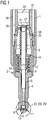
- Figure 1
- a valve group for an injector,
- Figure 2
- a detailed view of a cartridge tip and a first embodiment of a needle tip of the valve group,
- Figure 3
- a detailed view of the cartridge tip and a second embodiment of the needle tip,
- Figure 4
- a detailed view of the cartridge tip and a third embodiment of the needle tip,
- Figure 5
- a flow chart of a first method for manufacturing the valve group,
- Figure 6
- a flow chart of a second method for manufacturing the valve group.
- Elements of the same design and function that appear in the different illustrations are identified by the same reference character.
- A fluid injector (
figure 1 ) comprises an injector housing 1 and a valve group 2. The valve group 2 comprises acartridge 4, avalve cap 6 and aneedle 8. The injector may be used to inject fluid to a combustion chamber of an internal combustion engine. The injector may is connected to a high pressure fuel chamber, for example a common rail, of an internal combustion engine, where fuel is stored under high pressure, for example under the pressure of about 200 Bar. - The
cartridge 4 comprises acartridge recess 10. At one axial end facing away from thevalve cap 6 thecartridge 4 comprises acartridge tip 9. The cartridge recess 10 comprises a cartridge opening 11. Further, thecartridge 4 comprises twoboreholes 16. In an alternative embodiment thecartridge 4 may comprise only one ormore boreholes 16. - The
cartridge 4 takes in theneedle 8 movable in axial direction. Theneedle 8 comprises aneedle tip 13 facing away from thevalve cap 6. Theneedle 8 further comprises an end face 15 facing away from theneedle tip 13. - A
spring 12 is arranged between thecartridge 4 and aspring washer 14. Thespring washer 14 forms a first spring rest for thespring 12. A second spring rest is formed preferably at one axial end of thecartridge 4 facing away from thecartridge tip 9. Thespring washer 14 is fixed to theneedle 8. Thespring 12 forces theneedle 8 via thespring washer 14 in order to press theneedle tip 13 against thecartridge opening 11. - The
valve cap 6 comprises acontrol recess 17 facing away from thecartridge 4. Bellows 18 prevent leaking of the fluid through thecontrol recess 17 of thevalve cap 6. The end face 15 of theneedle 8 protrudes in anactor housing 32. Anactor 34 is arranged in theactor housing 32 and comprises aground plate 36. Via theground plate 36 theactor 34 affects theneedle 8 at theend face 31 of theneedle 8. - The
needle 8 prevents in a closed position of the needle 8 a fluid flow through thecartridge opening 11. In the closed position of theneedle 8 theneedle tip 13 is pressed to thecartridge recess 10 from the outside of thecartridge recess 10 covering it sealing up thecartridge recess 10. So theneedle 8 prevents the fluid flow through thecartridge opening 11. Apart from the closed position theneedle tip 13 is moved away from thecartridge opening 11. So thecartridge opening 11 and theneedle 8 form an injection nozzle. The fluid may flow through the volume between the injector housing 1 and the actor housing 5. The fluid may enter the valve group 2 through afluid recess 20 of thevalve cap 6. Then the fluid flows to thecartridge opening 11 and apart from the closed position of theneedle 8 the fluid is injected to the combustion chamber of the internal combustion engine. The axial position of theneedle 8 depends on a force balance. A first force is affected by thespring 12 in closing direction of theneedle 8 and a second force is affected by theactor 34 in opening direction of theneedle 8. Further forces on theneedle 8 are affected by the fluid in the valve group 2. - The
cartridge opening 11 comprises a conical part 42 (figure 2 ) of thecartridge 4 facing anaxis 43 of thecartridge 4. The diameter of the conical part 42 increases away from thevalve cap 6. For example an inner diameter and an outer diameter X of the conical part 42 may be called characteristic diameters of thecartridge 4. At an alternative embodiment of thecartridge 4 there also may be more or less characteristic diameters of thecartridge 4, for example: if thecartridge opening 11 comprises a second conical part and/or a cylindrical part, one diameter of the conical part and/or respectively the diameter of the cylindrical part of thecartridge opening 11 may be called characteristic diameter of thecartridge 4. The outer diameter X of the conical part 42 in cooperation with theneedle tip 13 is very important for an accurate dosing of the fluid and for avoiding coking. The coking may results at a high temperature by not completely burned fluid and/or dirt in the fluid. Theneedle tip 13 comprises acylindrical part 40 which comprises a diameter F_X. A characteristic geometry of theneedle 8 may comprise thecylindrical part 40 of theneedle 8. - The
needle tip 9 could also comprise a conical part 44 (Figure 3 ). Theconical part 44 borders thecylindrical part 40. Alternatively the conical 44 part of theneedle tip 13 may include different cone angles with the axis of the needle 8 (Figure 4 ). The characteristic geometry of theneedle 8 may comprise theconical part 44 of theneedle 8. The characteristic geometry of theneedle 8 may also comprise a further part of theneedle 8 which is relevant for reducing the coking at thecartridge tip 9 and/or theneedle tip 13. - To ensure a very good fit between the
cartridge tip 9 and theneedle tip 13 the valve group 2 is preferably manufactured by the following steps. In a first step S1 (figure 5 ), thecartridge 4 and theneedle 8 are assembled to the tools which are operable to manufacture thecartridge 4 and respectively theneedle 8. In a second step S2 thecartridge 4 and, in particular, one or more characteristic diameters of thecartridge 4 are manufactured. In a third step S3, the one or more characteristic diameters of thecartridge 4 are measured. In a fourth step S4 at least one characteristic geometry of theneedle 8 is manufactured dependent on thecartridge 4, in particular dependent on the characteristic diameters. In a step S5 theneedle 8 and thecartridge 4 are assembled together. So some deviations of the one or more measured characteristic diameters which occur while manufacturing thecartridge 4 are transferred to the at least one characteristic geometry of therespective needle 8. This contributes to a very precise fit of theneedle 8 to thecartridge 4 despite the deviations. - Alternatively the second step S2, the third step S3 and the fourth step S4 are substituted by a sixth and a seventh step S6, S7. In the sixth step S6 the tools for manufacturing the
cartridge 4 or respectively the at least one characteristic geometry of theneedle 8 are mechanically coupled together in a way that the tool for manufacturing the at least one characteristic geometry of theneedle 8 can follow the tool for manufacturing thecartridge 4. In the seventh step S7 the one or more characteristic diameters of thecartridge 4 are manufactured simultaneously with the characteristic geometry of theneedle 8 comprising the diameter F_X.
Claims (4)
- Method for manufacturing a valve group (2) having a cartridge (4) with a cartridge recess (10) in which a needle (8) is arranged movable in axial direction, the cartridge (4) and the needle (8) preventing a fluid flow through a cartridge opening (11) in a closed position of the needle (8) and otherwise enabling the fluid flow through the cartridge opening (11), the method comprising the steps of:- manufacturing the cartridge recess (10) having one or more diameters of at least one cylindrical and/or at least one conical part of the cartridge recess (10),- manufacturing at least one cylindrical and/or at least one conical part of the respective needle (8) for the cartridge (4) dependent on the one or, respectively, more diameters of the cylindrical and/or, respectively, the conical part of the cartridge recess (10),- assembling the cartridge (4) and the respective needle (8), the method being characterized in that it comprises a step of manufacturing the cartridge (4) and the cylindrical and/or, respectively, conical part of the needle (8) simultaneously, the tools for manufacturing the cylindrical and/or, respectively, conical parts of the cartridge (4) and, respectively, the needle (8) being mechanically coupled together in such a way that the tool for manufacturing the cylindrical and/or, respectively, conical part of the needle (8) follows the tool for manufacturing the cartridge (4).
- Method in accordance with claim 1 comprising a step of measuring the one or, respectively, more diameters of the cylindrical and/or, respectively, conical part of the cartridge (4) and manufacturing the diameter of the cylindrical and/or, respectively, conical part of the needle (8) dependent on the measured one or respectively more diameters of the cylindrical and/or, respectively, conical part of the cartridge (4).
- Method in accordance with one of the preceding claims comprising a step of manufacturing a cylindrical part (40) at a needle tip (13) which works together as an injection nozzle with a cartridge tip (9) at the cartridge opening (11), the cylindrical part (40) sticking out the cartridge recess (10) and having a diameter (F_X) which is a function of a diameter (X_T) of the cartridge opening (11).
- Apparatus for manufacturing a valve group (2) according to the method of claim 1 having a cartridge (4) with a cartridge recess (10) in which a respective needle (8) is arranged movable in axial direction, the cartridge (4) and the respective needle (8) preventing a fluid flow through an cartridge opening (11) in a closed position of the respective needle (8) and otherwise enabling the fluid flow through the cartridge opening (11), the apparatus is operable to:- manufacturing the cartridge recess (10) having one or more diameters of at least one cylindrical and/or at least one conical part of the cartridge recess (10),- manufacturing at least one cylindrical and/or at least one conical part of the respective needle (8) for the cartridge (4) dependent on the one or, respectively, more diameters of the cylindrical and/or, respectively, the conical part of the cartridge recess (10),- assembling the cartridge (4) and the respective needle (8).
Priority Applications (1)
| Application Number | Priority Date | Filing Date | Title |
|---|---|---|---|
| EP05020821.4A EP1767774B1 (en) | 2005-09-23 | 2005-09-23 | Method and apparatus for manufacturing a valve group for an injector |
Applications Claiming Priority (1)
| Application Number | Priority Date | Filing Date | Title |
|---|---|---|---|
| EP05020821.4A EP1767774B1 (en) | 2005-09-23 | 2005-09-23 | Method and apparatus for manufacturing a valve group for an injector |
Publications (2)
| Publication Number | Publication Date |
|---|---|
| EP1767774A1 EP1767774A1 (en) | 2007-03-28 |
| EP1767774B1 true EP1767774B1 (en) | 2018-01-10 |
Family
ID=35840257
Family Applications (1)
| Application Number | Title | Priority Date | Filing Date |
|---|---|---|---|
| EP05020821.4A Expired - Lifetime EP1767774B1 (en) | 2005-09-23 | 2005-09-23 | Method and apparatus for manufacturing a valve group for an injector |
Country Status (1)
| Country | Link |
|---|---|
| EP (1) | EP1767774B1 (en) |
Family Cites Families (4)
| Publication number | Priority date | Publication date | Assignee | Title |
|---|---|---|---|---|
| IT1226476B (en) * | 1987-03-12 | 1991-01-16 | Weber Srl | PROCEDURE AND EQUIPMENT TO CREATE INJECTOR VALVES FOR INTERNAL COMBUSTION ENGINES WITH IGNITION |
| DE19907678A1 (en) * | 1999-02-23 | 2000-08-24 | Hydraulik Ring Gmbh | Control edge manufacturing method for valve, preferably for fuel injector of combustion machine, manufacturing co-operating control edges in single processing step by device of single tool |
| US6920690B1 (en) * | 1999-04-27 | 2005-07-26 | Siemens Vdo Automotive Corp. | Method of manufacturing a fuel injector seat |
| DE10226397B4 (en) * | 2002-06-13 | 2004-05-27 | Siemens Ag | Method for setting the nozzle opening pressure of an injection nozzle and arrangement for carrying out the method |
-
2005
- 2005-09-23 EP EP05020821.4A patent/EP1767774B1/en not_active Expired - Lifetime
Non-Patent Citations (1)
| Title |
|---|
| None * |
Also Published As
| Publication number | Publication date |
|---|---|
| EP1767774A1 (en) | 2007-03-28 |
Similar Documents
| Publication | Publication Date | Title |
|---|---|---|
| KR101857463B1 (en) | Valve assembly for an injection valve, injection valve and method for assembling a valve assembly of an injection valve | |
| DE10361769B4 (en) | Pressure transducer with one-piece housing | |
| EP1601945B1 (en) | Method, device, and computer program for measuring the leakage of injection systems, especially for internal combustion engines of motor vehicles | |
| DE10146747A1 (en) | Fuel injection device for an internal combustion engine | |
| EP1561942B1 (en) | Fluid injector and its method of manufacture | |
| JP2004505204A (en) | Fuel injection valve and adjustment method thereof | |
| US7841320B2 (en) | Actuator unit and method for manufacturing an actuator unit | |
| EP1767774A1 (en) | Method and apparatus for manufacturing a valve group for an injector | |
| US20050098660A1 (en) | Fuel-injection valve for internal combustion engines | |
| JP2006138311A (en) | Fuel injector for internal combustion engines | |
| EP1803929B1 (en) | Fluid injector and method for manufacturing a fluid injector | |
| JP3837774B2 (en) | Electromagnetic fuel injection valve | |
| EP1445477A1 (en) | Metering device with flow calibrator and method for setting a flow rate of a metering device | |
| EP1918575B1 (en) | Injector for dosing fluid and method for assembling the injector | |
| EP1845253A1 (en) | Fuel injector for an internal-combustion engine | |
| EP1795741A1 (en) | Needle device | |
| EP1936182B1 (en) | Method for manufacturing a fluid injector | |
| EP1724464B1 (en) | Injector and valve group for the injector | |
| US7478626B2 (en) | Method for producing an injector | |
| EP1918571B1 (en) | Injector for dosing fluid | |
| EP1816343B1 (en) | Pre-treatment assembly and method for pre-treating a compensation device | |
| CN119593919A (en) | Oil nozzle and oil sprayer for measurement and oil nozzle ball head temperature peak value measurement method | |
| EP1865194B1 (en) | Method for adjusting an injection valve | |
| EP1811167A1 (en) | Injector, compensation assembly for the injector, and relieving device for the compensation assembly and method of assembling and calibrating the injector | |
| US20080230635A1 (en) | Fluid Injector |
Legal Events
| Date | Code | Title | Description |
|---|---|---|---|
| PUAI | Public reference made under article 153(3) epc to a published international application that has entered the european phase |
Free format text: ORIGINAL CODE: 0009012 |
|
| AK | Designated contracting states |
Kind code of ref document: A1 Designated state(s): AT BE BG CH CY CZ DE DK EE ES FI FR GB GR HU IE IS IT LI LT LU LV MC NL PL PT RO SE SI SK TR |
|
| AX | Request for extension of the european patent |
Extension state: AL BA HR MK YU |
|
| 17P | Request for examination filed |
Effective date: 20070919 |
|
| AKX | Designation fees paid |
Designated state(s): DE FR IT |
|
| RAP1 | Party data changed (applicant data changed or rights of an application transferred) |
Owner name: CONTINENTAL AUTOMOTIVE GMBH |
|
| 17Q | First examination report despatched |
Effective date: 20100920 |
|
| RIC1 | Information provided on ipc code assigned before grant |
Ipc: F02M 61/08 20060101ALI20160415BHEP Ipc: F02M 61/16 20060101AFI20160415BHEP Ipc: F02M 61/18 20060101ALI20160415BHEP Ipc: F02M 65/00 20060101ALI20160415BHEP |
|
| GRAP | Despatch of communication of intention to grant a patent |
Free format text: ORIGINAL CODE: EPIDOSNIGR1 |
|
| INTG | Intention to grant announced |
Effective date: 20170817 |
|
| GRAS | Grant fee paid |
Free format text: ORIGINAL CODE: EPIDOSNIGR3 |
|
| GRAA | (expected) grant |
Free format text: ORIGINAL CODE: 0009210 |
|
| AK | Designated contracting states |
Kind code of ref document: B1 Designated state(s): DE FR IT |
|
| REG | Reference to a national code |
Ref country code: DE Ref legal event code: R096 Ref document number: 602005053328 Country of ref document: DE |
|
| REG | Reference to a national code |
Ref country code: DE Ref legal event code: R097 Ref document number: 602005053328 Country of ref document: DE |
|
| PGFP | Annual fee paid to national office [announced via postgrant information from national office to epo] |
Ref country code: IT Payment date: 20180925 Year of fee payment: 14 |
|
| PLBE | No opposition filed within time limit |
Free format text: ORIGINAL CODE: 0009261 |
|
| STAA | Information on the status of an ep patent application or granted ep patent |
Free format text: STATUS: NO OPPOSITION FILED WITHIN TIME LIMIT |
|
| 26N | No opposition filed |
Effective date: 20181011 |
|
| PGFP | Annual fee paid to national office [announced via postgrant information from national office to epo] |
Ref country code: DE Payment date: 20180930 Year of fee payment: 14 |
|
| PG25 | Lapsed in a contracting state [announced via postgrant information from national office to epo] |
Ref country code: FR Free format text: LAPSE BECAUSE OF NON-PAYMENT OF DUE FEES Effective date: 20180930 |
|
| REG | Reference to a national code |
Ref country code: DE Ref legal event code: R119 Ref document number: 602005053328 Country of ref document: DE |
|
| PG25 | Lapsed in a contracting state [announced via postgrant information from national office to epo] |
Ref country code: DE Free format text: LAPSE BECAUSE OF NON-PAYMENT OF DUE FEES Effective date: 20200401 |
|
| PG25 | Lapsed in a contracting state [announced via postgrant information from national office to epo] |
Ref country code: IT Free format text: LAPSE BECAUSE OF NON-PAYMENT OF DUE FEES Effective date: 20190923 |