EP1767765A2 - Engine combustion controlling method and device - Google Patents
Engine combustion controlling method and device Download PDFInfo
- Publication number
- EP1767765A2 EP1767765A2 EP06254967A EP06254967A EP1767765A2 EP 1767765 A2 EP1767765 A2 EP 1767765A2 EP 06254967 A EP06254967 A EP 06254967A EP 06254967 A EP06254967 A EP 06254967A EP 1767765 A2 EP1767765 A2 EP 1767765A2
- Authority
- EP
- European Patent Office
- Prior art keywords
- cylinders
- engine
- phase angle
- crank
- combustion
- Prior art date
- Legal status (The legal status is an assumption and is not a legal conclusion. Google has not performed a legal analysis and makes no representation as to the accuracy of the status listed.)
- Granted
Links
Images



Classifications
-
- F—MECHANICAL ENGINEERING; LIGHTING; HEATING; WEAPONS; BLASTING
- F02—COMBUSTION ENGINES; HOT-GAS OR COMBUSTION-PRODUCT ENGINE PLANTS
- F02D—CONTROLLING COMBUSTION ENGINES
- F02D41/00—Electrical control of supply of combustible mixture or its constituents
- F02D41/008—Controlling each cylinder individually
- F02D41/0082—Controlling each cylinder individually per groups or banks
-
- F—MECHANICAL ENGINEERING; LIGHTING; HEATING; WEAPONS; BLASTING
- F02—COMBUSTION ENGINES; HOT-GAS OR COMBUSTION-PRODUCT ENGINE PLANTS
- F02P—IGNITION, OTHER THAN COMPRESSION IGNITION, FOR INTERNAL-COMBUSTION ENGINES; TESTING OF IGNITION TIMING IN COMPRESSION-IGNITION ENGINES
- F02P15/00—Electric spark ignition having characteristics not provided for in, or of interest apart from, groups F02P1/00 - F02P13/00 and combined with layout of ignition circuits
- F02P15/08—Electric spark ignition having characteristics not provided for in, or of interest apart from, groups F02P1/00 - F02P13/00 and combined with layout of ignition circuits having multiple-spark ignition, i.e. ignition occurring simultaneously at different places in one engine cylinder or in two or more separate engine cylinders
-
- F—MECHANICAL ENGINEERING; LIGHTING; HEATING; WEAPONS; BLASTING
- F01—MACHINES OR ENGINES IN GENERAL; ENGINE PLANTS IN GENERAL; STEAM ENGINES
- F01N—GAS-FLOW SILENCERS OR EXHAUST APPARATUS FOR MACHINES OR ENGINES IN GENERAL; GAS-FLOW SILENCERS OR EXHAUST APPARATUS FOR INTERNAL-COMBUSTION ENGINES
- F01N13/00—Exhaust or silencing apparatus characterised by constructional features
- F01N13/08—Other arrangements or adaptations of exhaust conduits
- F01N13/10—Other arrangements or adaptations of exhaust conduits of exhaust manifolds
- F01N13/107—More than one exhaust manifold or exhaust collector
-
- F—MECHANICAL ENGINEERING; LIGHTING; HEATING; WEAPONS; BLASTING
- F02—COMBUSTION ENGINES; HOT-GAS OR COMBUSTION-PRODUCT ENGINE PLANTS
- F02D—CONTROLLING COMBUSTION ENGINES
- F02D2250/00—Engine control related to specific problems or objectives
- F02D2250/18—Control of the engine output torque
-
- F—MECHANICAL ENGINEERING; LIGHTING; HEATING; WEAPONS; BLASTING
- F02—COMBUSTION ENGINES; HOT-GAS OR COMBUSTION-PRODUCT ENGINE PLANTS
- F02D—CONTROLLING COMBUSTION ENGINES
- F02D41/00—Electrical control of supply of combustible mixture or its constituents
- F02D41/02—Circuit arrangements for generating control signals
- F02D41/14—Introducing closed-loop corrections
- F02D41/1497—With detection of the mechanical response of the engine
- F02D41/1498—With detection of the mechanical response of the engine measuring engine roughness
Definitions
- the present invention relates to a method and device of controlling combustions of an engine, to an engine arrangement, motorcycle and vehicle equipped with the device, for improving a passenger's feel of an engine beat, as well as to a camshaft arrangement
- the flat crankshaft is one wherein phase angles of crank pins of the crankshaft (that is, crank pin angles) are arranged at 0 or 180 degrees.
- crank pin angles For example, No. 1 and No. 4 cylinders may have the same crank pin angle, and with respect to the crank pin angles of these cylinders, crank pin angles of No. 2 and No. 3 cylinders may be configured to be apart from the crank pin angles of No. 1 and No. 4 cylinders by 180 degrees.
- a combustion control called “equally-intervaled combustion” may be carried out.
- the equally-intervaled combustion for the flat crankshaft is such that combustions of cylinders are sequentially carried out one by one as the crankshaft rotates every 180 degrees.
- a combustion of No. 1 cylinder (#1) is carried out when the crank phase angle is 0 degree
- a combustion of No. 2 cylinder (#2) is carried out when the crank phase angle is 180 degrees
- a combustion of No. 4 cylinder (#4) is carried out when the crank phase angle is 360 degrees
- a combustion of No. 3 cylinder (#3) is carried out when the crank phase angle is 540 degrees, so that a predetermined rhythm (feel of an engine beat) is produced.
- the feel of the engine beat of the equally-intervaled combustion is monotonous to the passenger.
- the feel of the engine beat is important because it dictates a ride quality and, thus, a development of an engine with a more comfortable feel of the engine beat has been always demanded.
- the present invention seeks to address the conditions, and to provide a method and device, engine arrangement, motorcycle and vehicle equipped with the device, of controlling combustion of an engine with a more comfortable feel of an engine beat.
- a device for controlling combustions of an engine with three or more pistons of cylinders per crankshaft includes a first module for causing simultaneous combustions of two cylinders among the three or more cylinders, that have the same crank pin angle, and a second module for causing a combustion of at least one of the other cylinders, offsetting a crank phase angle by a first crank phase angle, wherein the first module repeats the combustions from the first two cylinders, further offsetting the crank phase angle by a second crank phase angle.
- the crankshaft may be a flat crankshaft in which crank pin angles are 0 and 180 degrees.
- crank pin angles are 0 and 180 degrees.
- the first crank phase angle is 180 degrees
- the second crank phase angle is 540 degrees
- two cylinders in which combustion is simultaneously carried out by the first module may have the same crank pin angle as each other, and two remaining cylinders may also have the same crank pin angle as each other.
- these cylinder pairs may be offset by 180 degrees in the crank pin angle from each other. For this reason, if the simultaneous combustion of both cylinder pairs are carried out, even larger and sharper feel of the engine beat can be obtained.
- combustion of one cylinder of one cylinder pair may be carried out while offsetting the crank phase angle by 180 degrees from that of the first module, and combustion of a remaining cylinder of this cylinder pair may be carried out while offsetting the crank phase angle by 360 degrees.
- a milder feel of the engine beat than when the simultaneous combustion of this cylinder pair is carried out can be obtained.
- the engine is configured to control combustion of a corresponding cylinder based on a rotational angle position of a camshaft of the engine detected by a cam sensor with which the engine is equipped, if a detection point of the cam sensor is formed in a rotational angle position on the camshaft other than a rotational angle position corresponding to a timing in which cams on the camshaft contact tappets for valves of the engine corresponding to the cylinders of which the simultaneous combustions are carried out, the detection of the cam sensor is not carried out when the cams of the cylinders in which the simultaneous combustion is carried out operate the tappets and, thus, the detection of the cam sensor is stabilized.
- the combustion control device for the engine as described above may be suitable for a motorcycle equipped with the following exhaust pipes.
- a configuration in which exhaust pipes connected to the cylinders with the same crank pin angle is collected may be possible.
- an exhaust pulsation of non-180 degrees can be utilized and, thus, a motorcycle, that is powerful, and depending on a collected position, is possible to reduce a torque depression between torque peaks of each cylinder so that the entire torque fluctuation is smooth, can be realized.
- the method of controlling combustions of an engine having three or more pistons of cylinders per crankshaft may be provided.
- the method includes causing simultaneous combustions of two cylinders among the three or more cylinders, that have a same crank pin angle, causing a combustion of at least one another cylinder offsetting a crank phase angle by a first crank phase angle, and repeating from the combustions of the first two cylinders further offsetting the crank phase angle by a second crank phase angle from the first crank phase angle.
- simultaneous combustion patterns according to embodiments of the invention, torque peaks of an engine that are transmitted to a tire are unequally pitched.
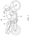
- Fig. 1 is a view showing a motorcycle 10 according to an embodiment of the present invention.
- the motorcycle 10 according to the embodiment includes an inline-four-cylinder engine 20 as its drive source.
- this drive source may be, but not limited to, other engines having a configuration in which pistons of three or more cylinders are supported by one crankshaft, such as V3, V8 engines, etc.
- exhaust pipes 30 are connected to exhaust ports (not shown) of the engine 20.
- the motorcycle 10 includes an ECU (Electronic Control Unit) 40 as a device for controlling combustions of the engine 20.
- ECU Electronic Control Unit
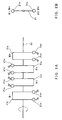
- Fig. 2A schematically shows an example of a crankshaft 21 of the engine 20, and Fig. 2B shows a side view thereof.
- This crankshaft 21 is a flat crankshaft in which phase angles of crank pins 21p of the crankshaft (crank pin angles) are arranged at 0 and 180 degrees.
- the crank pin angles of a No. 1 cylinder (#1) and a No. 4 cylinder (#4) of this crankshaft 21 are both arranged at the position of 0 degrees.
- the crank pin angles of a No. 2 cylinder (#2) and a No. 3 cylinder (#3) are both arranged at the position of 180 degrees.
- balance weights are provided opposite to the crank pin 21p of each cylinder so that the inertia of a piston and a connecting rod (not illustrated) which are attached to the crank pin 21p is cancelled out.
- a connecting rod not illustrated
- weight may be advantageously reduced.
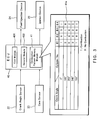
- an ECU 40 as a device for controlling combustions of an engine according to the present embodiment is connected to a crank angle sensor 22, a cam sensor 23, a fuel injection device 24, and an ignition device 25, of the engine 20.
- the crank angle sensor 22 typically outputs a pulse signal corresponding to a rotational angle position of the crankshaft 21.
- the cam sensor 23 outputs a pulse signal corresponding to the rotational angle position of a camshaft 26 (see Fig. 10).
- ECU 40 calculates the rotational angle position of the crankshaft 21 (that is, the crank phase angle) based on the pulse signal outputted from the crank angle sensor 22 and the cam sensor 23, respectively.
- the crank phase angle is calculated using both the crank angle sensor 22 and the cam sensor 23, it may also be possible to carry out a similar calculation using either one of the crank angle sensor or the cam sensor 23.
- ECU 40 includes a combustion pattern memory module 41.
- the combustion pattern memory module 41 stores a combustion pattern 41 a that indicates in which cylinder a combustion is to be carried out in accordance with the crank phase angle.
- the combustion pattern 41a shown in Fig. 3 is merely an example, and it is to be appreciated that other combustion patterns may be used in a similar manner.
- whether or not a combustion is to be carried out for each cylinder at a predetermined crank phase angle is represented by "1" or "0".
- ECU 40 refers to the combustion pattern 41 a stored in the combustion pattern memory module 41 based on the crank phase angle calculated as mentioned above, and specifies the corresponding target cylinder for combustion. ECU 40 then outputs an instruction to the fuel injection device 24 and/or the ignition device 25 corresponding to the specified target cylinder for the combustion, and carries out the combustion or firing of the target cylinder.
- ECU 40 includes a first module 401 for carrying out simultaneous combustions of two cylinders that have the same crank phase angle, based on the combustion pattern 41 a, and a second module 402 for carrying out a combustion of at least one of the other cylinders (for example, two other cylinders) offsetting the crank phase angle by a first crank phase angle (for example, 180 degrees), based on the combustion pattern 41 a, wherein ECU 40 is configured so that it controls the engine to repeats from the combustions of the first two cylinders further offsetting the crank phase angle by a second crank phase angle.
- a first crank phase angle for example, 180 degrees
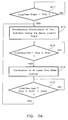
- ECU 40 first determines whether the crank phase angle is a predetermined crank phase angle PhA (Step S11), and repeats Step S11 until the crank phase angle becomes the predetermined crank phase angle PhA.
- ECU 40 determines that the crank phase angle is the predetermined crank phase angle PhA, it causes the first module 401 to carry out simultaneous combustions of two cylinders that have the same crank pin angle, based on the combustion pattern 41a (Step S12).
- ECU 40 determines whether the crank phase angle is offset by a first crank phase angle PhA1 from the predetermined crank phase angle PhA (Step S13), and repeats Step S13 until the crank phase angle becomes PhA+PhA1.
- ECU 40 determines that the crank phase angle is PhA+PhA1, it causes the second module 402 to carry out a combustion of at least one of the other cylinders, based on the combustion pattern 41a (Step S 14).
- ECU 40 determines whether the crank phase angle is further different by a second crank phase angle PhA2 (Step S 15), and repeats Step S 15 until the crank phase angle becomes PhA+PhA1+phA2.
- Step S 15 the crank phase angle becomes PhA+PhA1+phA2.
- the combustion pattern 41 a is described on the basis of a crankshaft revolution of 720 degrees per combustion cycle.
- the present invention is not however limited to this arrangement.
- the equally-intervaled combustions may be as shown in Fig. 4A.
- No. 1 cylinder (#1) carries out a combustion
- No. 2 cylinder (#2) when the crank phase angle is 180 degrees
- No. 4 cylinder (#4) when the crank phase angle is 360 degrees
- No. 3 cylinder (#3) when the crank phase angle is 540 degrees, and it repeats from a combustion of No. 1 cylinder (#1) since one combustion cycle is completed.
- combustion pattern 41a of the present embodiment of the invention may be shown as in Fig. 4B, for example.
- No. 1 and No. 4 cylinders (#1, #4) carry out combustions when the crank phase angle is 0 degrees
- No. 2 and No. 3 cylinders (#2, #3) carry out combustions when the crank phase angle is 180 degrees
- no combustion is carried out for any cylinder when the crank phase angle is 360 and 540 degrees
- this combustion pattern is a combustion pattern of what is called "a simultaneous combustion" in which combustions are simultaneously carried out for cylinders having the same crank pin angle.
- the simultaneous combustions are subsequently carried out at 0 and 180 degrees.
- a combustion pattern as shown in parentheses in Fig. 4B can be carried out. That is, a combustion pattern in which No. 2 and No. 3 cylinders (#2, #3) carry out combustions when the crank phase angle is 0 degrees, No. 1 and No. 4 cylinders (#1, #4) at 180 degrees, no combustion is carried out for any cylinder at 360 and 540 degrees, and it repeats from combustions of No. 2 and No. 3 cylinders (#2, #3).
- a combustion pattern as shown in Fig. 4C can be carried out. That is, a combustion pattern in which No. 1 and No. 4 cylinders (#1, #4) carry out combustions when the crank phase angle is 0 degrees, No. 2 cylinder (#2) at 180 degrees, no combustion is carried out for any cylinder at 360 degrees, No. 3 cylinder (#3) at 540 degrees, and it repeats combustions from No. 1 and No. 4 cylinders (#1, #4).
- a combustion pattern can be carried out in which No. 2 and No. 3 cylinders (#2, #3) carry out combustions when the crank phase angle is 0 degrees, No. 4 cylinder (#4) at 180 degree, no combustion is carried out for any cylinder at 360 degrees, No. 1 cylinder (#1) at 540 degrees, and it repeats combustions from No. 2 and No. 3 cylinders (#2, #3).
- the torque peaks of the engine 20, that are transmitted to a tire are unequally pitched.
- the output torque generated by one combustion becomes larger, it tends to repeat an alternation between slip and grip of the tire on a road surface, thereby obtaining a larger traction.
- a skid becomes smaller under the influence of the larger traction even when the motorcycle 10 goes into a corner.
- an exhaust sound is comparatively shrill in the equally-intervaled combustion, however, in the simultaneous combustion, the exhaust sound is at a lower frequency, and of non-equal intervals, and, thus, it is possible to give passenger(s) a different feel of the engine beat from that of the equally-intervaled combustion.
- the exhaust sound is at a lower frequency, and of non-equal intervals, and, thus, it is possible to give passenger(s) a different feel of the engine beat from that of the equally-intervaled combustion.
- vibrations of the engine 20 may affect to the passenger(s) in a similar manner.
- an exhaust pipe assembly 30 to be connected to the engine 20 that is subject to such combustion control may take the following configurations according to embodiments of the invention.
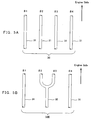
- the exhaust pipe assembly 30 may be configured so that it includes independent exhaust pipes 31, each of which being connected to exhaust ports (not shown) of each cylinder of the engine 20.
- FIG. 5B another exhaust pipe assembly 30B is shown in Fig. 5B, and is configured such that No. 2 and No. 3 cylinders (#2, #3) that carry out the simultaneous combustions are connected to a collecting pipe 32 that is collected in an intermediate position, and the remaining cylinders are connected to straight exhaust pipes 31 similar to that shown in Fig. 5A.
- a collecting pipe 32 that is collected in an intermediate position
- the remaining cylinders are connected to straight exhaust pipes 31 similar to that shown in Fig. 5A.
- exhaust pulsations of non-180 degrees can be utilised, even if it utilises any of the combustion patterns (including the pattern in the parentheses) in Fig. 4B or the combustion pattern in the parentheses in Fig. 4C. That is, although a torque will be greater than the case in Fig.
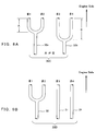
- FIG. 6A Another exhaust pipe assembly 30C is shown in Fig. 6A, and has a configuration in which a collecting pipe 32a is connected to No. 1 and No. 2 cylinders (#1, #2) that do not carry out the simultaneous combustion, and a collecting pipe 32b is connected to No. 3 and No. 4 cylinders (#3, #4) that do not carry out the simultaneous combustion.
- a collecting pipe 32a is connected to No. 1 and No. 2 cylinders (#1, #2) that do not carry out the simultaneous combustion
- a collecting pipe 32b is connected to No. 3 and No. 4 cylinders (#3, #4) that do not carry out the simultaneous combustion.
- the 180-degree exhaust pulsations can be utilized even for either of the combustion patterns of Figs. 4B and 4C. That is, a larger torque can be obtained although a torque peak is sharper than the case of Fig. 5B.
- the torque peaks of the entire engine smooth and mild by offsetting the torque phase angles may be adjusted by offsetting the collected position of the collecting pipe 32a (for example, the position shown by "A” in the figure) and the collected position of the collecting pipe 32b (for example, the position shown by "B” in the figure) (that is, "A # B") in the longitudinal direction of the pipes.
- the collected positions are shown as distances from the respective exhaust ports.
- FIG. 6B Another exhaust pipe assembly 30D is shown in Fig. 6B, and has a configuration in which the collecting pipe 32 is connected to No. 1 and No. 2 cylinders (#1, #2) that do not carry out the simultaneous combustion, and straight exhaust pipes 31 are connected to No. 3 and No. 4 cylinders (#3, #4). According to this configuration, exhaust pulsations of non-180 degree can be utilized for at least No. 1 and No. 2 cylinders (#1, #2) even for either of the combustion patterns of Figs. 4B and 4C.
- Fig. 7 shows a still another combustion pattern of an embodiment of the present invention.
- This combustion pattern is such that a combustion of No. 2 cylinder (#2) is carried out when the crank phase angle is 0 degrees, combustions of No. 1 and No. 4 cylinders (#1, #4) are carried out at 180 degrees, a combustion of No. 3 cylinder (#3) is carried out at 360 degrees, no combustion is carried out for any of the cylinders at 540 degrees, and the pattern is repeated from the combustion of No. 2 cylinder (#2).
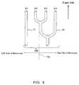
- An example of an exhaust pipe assembly 30E suitable for the combustion pattern shown in Fig. 7 has a configuration in which the straight exhaust pipe 31 is connected to No. 1 cylinder (#1) that carries out the simultaneous combustion with No. 4 cylinder (#4), and a collecting pipe 33 is connected to No. 2 through No. 4 cylinders (#2, #3, and #4) that do not carry out the simultaneous combustion.
- the collecting pipe 33 of this example collects No. 2 and No. 3 cylinders (#2, #3) and then further collects No. 4 cylinder (#4) on a more downstream side.
- the straight exhaust pipe 31 is arranged on either of the left or right sides of the motorcycle body, and the collecting pipe 33 is arranged on the other side.
- a center line 10c of the motorcycle body is schematically shown by an one-point chain line.
- the straight exhaust pipe 31 is arranged on the left side of the body (exit left), and the collecting pipe 33 is arranged on the right side of the body (exit right).
- Fig. 8 it is also possible to further collect the collecting pipe 33 that collects No. 2, No. 3, and No. 4 cylinders (#2, #3, and #4) with the straight exhaust pipe 31 being connected to No. 1 cylinder (#1), and to arrange the collected pipe on either of the left or right sides of the motorcycle body.
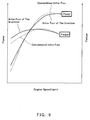
- Fig. 9 shows a relationship between an output (power) and torque corresponding to an engine speed under a control according to the combustion pattern of the simultaneous combustion shown in Fig. 7, while comparing with a control under the combustion pattern of the conventional equally-intervaled combustion.
- the output and torque under the control according to the combustion pattern of the equally-intervalled combustion are shown by dashed lines
- the output and torque under the control according to the combustion pattern of the simultaneous combustion are shown by solid lines, respectively.
- the output and torque in a low-speed region have been improved by the simultaneous combustion.
- a reference numeral 26 represents the camshaft of the engine 20 (see Fig. 1) configured so that No. 1 and No. 4 cylinders (#1, #4) carry out the simultaneous combustions. Although it is configured so that No. 1 and No. 4 cylinders (#1, #4) carry out the simultaneous combustions in the present configuration, this method may be similarly applicable to configurations wherein other cylinders carry out the simultaneous combustions. Further, this camshaft 26 may be applicable to either on the air-intake or exhaust side.
- a detecting portion 23a of the cam sensor 23 is typically configured such that it outputs a pulse signal when it passes a detection point 26a of the cam sensor 23 that is provided at a position on the circumference of the camshaft 26, the pulse signal may become unstable. Therefore, it is desirable to determine the installation position of the detection point 26a of the cam sensor 23 other than such a position of the circumference of the camshaft 26.
- the camshaft 26 has a relationship in which it carries out one revolution while the crankshaft 21 carries out two revolutions.
- the cam sensor 23 is provided to determine whether the crankshaft 21 that carries out two revolutions during one combustion cycle is in the first revolution or in the second revolution.
- the detection point 26a may according to embodiments of the invention also be provided on a suitable extended shaft that is directly or indirectly connected with the camshaft 26, or an arbitrary mechanism coupled to the camshaft 26 or the extended shaft through a gear train, etc.
- the detection point 26a is arranged so that it passes the detecting portion 23a immediately before the cam 261 and 264 corresponding to No. 1 and No. 4 cylinders (#1, #4) push the corresponding tappets 27. Therefore, in Fig. 10, the detection point 26a should not be provided within an angle range corresponding to the time from when the cams 261 and 264 start pushing the tappets 27 until when the cams 261 and 264 stop pushing the tappets 27, and, therefore, the angle range is shown as an "NG" range. That is, the detection point 26a may be provided in any angle positions other than this "NG" range, and, therefore, the range where the detection point 26a should be provided is shown as an "OK" range.
- 110A and 110B in Fig. 11 represent displacements of air-intake valves and exhaust valves according to the crank angle (the crank phase angle).
- 110A represents the case where No. 1 and No. 4 cylinders (#1, #4) are configured to carry out the simultaneous combustions
- 110B represents the case where No. 2 and No. 3 cylinders (#2, #3) are configured to carry out the simultaneous combustions, respectively.
- intake strokes of No. 1 and No. 4 cylinders (#1, #4) stretches from 360 degrees to 630 degrees in the crank angle, and, typically, air-intake valves open from 320 degrees to 620 degrees in the crank angle, that is, it is a state where the cams on the air-intake side contact the tappets.
- an exhaust stroke stretches from 90 degrees to 360 degrees in the crank angle, and, typically, exhaust valves open from 100 degrees to 400 degrees in the crank angle, that is, it is in a state where the cams on the exhaust side contacts the tappets.
- the detecting portion 23a may be provided anywhere from 620 degrees to 320 degrees for the stable pulse signals as mentioned above.
- the detecting portion 23a may be provided anywhere from 400 degrees to 100 degrees.
- An ignition is carried out at 180 degrees in the crank angle, an exhaust stroke stretches from 270 degrees to approximately 540 degrees in the crank angle, and, typically, the exhaust valves open from 280 degrees to 580 degrees in the crank angle, that is, it is in a state where the cams on the exhaust side contact the tappets.
- the detecting portion 23a may be provided anywhere from 580 degrees to 280 degrees.
- the detecting portion 23a may be provided anywhere from 580 degrees to 100 degrees.
- cam sensor 23 as shown in Fig. 10 has been provided in an upper side, it will be appreciated that it may be provided any position as long as the above-mentioned relationship of the rotational angle position of the camshaft 26 is satisfied.
Landscapes
- Engineering & Computer Science (AREA)
- Chemical & Material Sciences (AREA)
- Combustion & Propulsion (AREA)
- Mechanical Engineering (AREA)
- General Engineering & Computer Science (AREA)
- Combined Controls Of Internal Combustion Engines (AREA)
- Exhaust Silencers (AREA)
- Electrical Control Of Air Or Fuel Supplied To Internal-Combustion Engine (AREA)
- Shafts, Cranks, Connecting Bars, And Related Bearings (AREA)
Abstract
Description
- The present application claims priority from
Japanese Patent Application No. 2005-277395 filed September 26, 2005 - The present invention relates to a method and device of controlling combustions of an engine, to an engine arrangement, motorcycle and vehicle equipped with the device, for improving a passenger's feel of an engine beat, as well as to a camshaft arrangement
- For example, in an inline-four-cylinder engine, it is configured to support pistons of four cylinders per crankshaft. In the engine of such a configuration, there are some which adopt a flat crankshaft (see Examined
Japanese Patent Publication No. HEI 7-26546 - The flat crankshaft is one wherein phase angles of crank pins of the crankshaft (that is, crank pin angles) are arranged at 0 or 180 degrees. For example, No. 1 and No. 4 cylinders may have the same crank pin angle, and with respect to the crank pin angles of these cylinders, crank pin angles of No. 2 and No. 3 cylinders may be configured to be apart from the crank pin angles of No. 1 and No. 4 cylinders by 180 degrees.
- Generally, in the engine which adopts such a flat crankshaft, a combustion control called "equally-intervaled combustion" may be carried out. The equally-intervaled combustion for the flat crankshaft is such that combustions of cylinders are sequentially carried out one by one as the crankshaft rotates every 180 degrees. For example, a combustion of No. 1 cylinder (#1) is carried out when the crank phase angle is 0 degree, a combustion of No. 2 cylinder (#2) is carried out when the crank phase angle is 180 degrees, a combustion of No. 4 cylinder (#4) is carried out when the crank phase angle is 360 degrees, and a combustion of No. 3 cylinder (#3) is carried out when the crank phase angle is 540 degrees, so that a predetermined rhythm (feel of an engine beat) is produced.
- However, the feel of the engine beat of the equally-intervaled combustion is monotonous to the passenger. The feel of the engine beat is important because it dictates a ride quality and, thus, a development of an engine with a more comfortable feel of the engine beat has been always demanded.
- The present invention seeks to address the conditions, and to provide a method and device, engine arrangement, motorcycle and vehicle equipped with the device, of controlling combustion of an engine with a more comfortable feel of an engine beat.
- According to one aspect of the present invention, a device for controlling combustions of an engine with three or more pistons of cylinders per crankshaft is provided. The device includes a first module for causing simultaneous combustions of two cylinders among the three or more cylinders, that have the same crank pin angle, and a second module for causing a combustion of at least one of the other cylinders, offsetting a crank phase angle by a first crank phase angle, wherein the first module repeats the combustions from the first two cylinders, further offsetting the crank phase angle by a second crank phase angle.
- According to this aspect of the invention, it is possible to obtain a feel of an engine beat that is different from the equally-intervaled combustion, because combustions of two cylinders having the same crank pin angle among three or more cylinders are carried out, that is, the simultaneous combustion is carried out.
- The crankshaft may be a flat crankshaft in which crank pin angles are 0 and 180 degrees. Thus, a torque during the simultaneous combustion is approximately doubled, and a larger and sharper feel of the engine beat can be obtained.
- For example, in the case of an inline-four-cylinder engine having a flat crankshaft, it is preferable that the first crank phase angle is 180 degrees, and the second crank phase angle is 540 degrees.
- In the case of an engine with pistons of four cylinders per crankshaft, that is, the inline-four-cylinder engine, and the crankshaft is the flat crankshaft, two cylinders in which combustion is simultaneously carried out by the first module may have the same crank pin angle as each other, and two remaining cylinders may also have the same crank pin angle as each other. However, these cylinder pairs may be offset by 180 degrees in the crank pin angle from each other. For this reason, if the simultaneous combustion of both cylinder pairs are carried out, even larger and sharper feel of the engine beat can be obtained. Further, it is possible that combustion of one cylinder of one cylinder pair may be carried out while offsetting the crank phase angle by 180 degrees from that of the first module, and combustion of a remaining cylinder of this cylinder pair may be carried out while offsetting the crank phase angle by 360 degrees. Thus, a milder feel of the engine beat than when the simultaneous combustion of this cylinder pair is carried out can be obtained.
- In the case that the engine is configured to control combustion of a corresponding cylinder based on a rotational angle position of a camshaft of the engine detected by a cam sensor with which the engine is equipped, if a detection point of the cam sensor is formed in a rotational angle position on the camshaft other than a rotational angle position corresponding to a timing in which cams on the camshaft contact tappets for valves of the engine corresponding to the cylinders of which the simultaneous combustions are carried out, the detection of the cam sensor is not carried out when the cams of the cylinders in which the simultaneous combustion is carried out operate the tappets and, thus, the detection of the cam sensor is stabilized.
- The combustion control device for the engine as described above may be suitable for a motorcycle equipped with the following exhaust pipes.
- For example, a configuration in which exhaust pipes connected to the cylinders with the same crank pin angle is collected may be possible. In this case, an exhaust pulsation of non-180 degrees can be utilized and, thus, a motorcycle, that is powerful, and depending on a collected position, is possible to reduce a torque depression between torque peaks of each cylinder so that the entire torque fluctuation is smooth, can be realized.
- Further, for example, a configuration in which exhaust pipes connected to cylinders that differ 180 degrees in the crank pin angle, respectively are collected, may be possible. In this case, an exhaust pulsation of 180 degrees can be utilized and, thus, a powerful motorcycle with a sharp torque peak can be realized.
- Further, if every two exhaust pipes are to be collected, and collected positions of these exhaust pipe pairs are offset in the longitudinal direction of the exhaust pipes, it is possible to effectively utilize an exhaust pulsation of 180 degrees, reduce a depression of the torque between the torque peaks of each cylinder, and smooth the entire torque fluctuations.
- Further, a configuration in which the collected exhaust pipes are further collected with the other exhaust pipes connected to cylinders having the same crank pin angle or a different crank pin angle by 180 degrees may also be possible. In this case, a result in which the functions and effects as mentioned above are combined can be obtained.
- According to another aspect of the present invention, the method of controlling combustions of an engine having three or more pistons of cylinders per crankshaft may be provided. The method includes causing simultaneous combustions of two cylinders among the three or more cylinders, that have a same crank pin angle, causing a combustion of at least one another cylinder offsetting a crank phase angle by a first crank phase angle, and repeating from the combustions of the first two cylinders further offsetting the crank phase angle by a second crank phase angle from the first crank phase angle.
According to simultaneous combustion patterns according to embodiments of the invention, torque peaks of an engine that are transmitted to a tire are unequally pitched. Thus, since the output torque generated by one combustion becomes larger, it tends to repeat an alternation between slip and grip of the tire on a road surface, thereby obtaining a larger traction. Further, a skid becomes smaller under the influence of the larger traction even when a motorcycle according to an embodiment of the invention goes into a corner.
Further, an exhaust sound is comparatively shrill in the equally-intervaled combustion, however, in the simultaneous combustion, the exhaust sound is at a lower frequency, and of non-equal intervals, and, thus, it is possible to give passenger(s) a different feel of the engine beat from that of the equally-intervaled combustion. In the meantime, it is noted that not only the exhaust sound, but also vibrations of the engine may affect the passenger(s) in a similar manner. - The disclosure is illustrated by way of example and not by way of limitation in the figures of the accompanying drawings, in which the like reference numerals indicate similar elements and in which:
- Fig. 1 is a schematic view from the right side, showing a configuration of a motorcycle according to an embodiment of the present invention.
- Fig. 2A is a schematic view showing a configuration of a crankshaft of an engine of the motorcycle shown in Fig. 1.
- Fig. 2B is a side view of Fig. 2A.
- Fig. 3 is a block diagram showing a configuration of a combustion control device of the motorcycle shown in Fig. 1.
- Fig. 3A is a flowchart showing an example of the engine combustion control of ECU shown in Fig. 3.
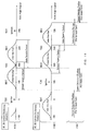
- Fig. 4A is a graph showing a conventional combustion control pattern of an equally-intervaled combustion.
- Fig. 4B is a graph showing an example of a combustion control pattern of a simultaneous combustion by the combustion control device shown in Fig. 3.
- Fig. 4C is a graph showing another example of the combustion control pattern of the simultaneous combustion by the combustion control device shown in Fig. 3.
- Fig. 5A is a schematic view showing an example of a configuration of exhaust pipes suitable for the engine of the motorcycle shown in Fig. 1.
- Fig. 5B is a schematic view showing another example of the configuration of the exhaust pipes suitable for the engine of the motorcycle shown in Fig. 1.
- Fig. 6A is a schematic view showing still another example of the configuration of the exhaust pipes suitable for the engine of the motorcycle shown in Fig. 1.
- Fig. 6B is a schematic view showing another example of the configuration of the exhaust pipes suitable for the engine of the motorcycle shown in Fig. 1.
- Fig. 7 shows still another example of the control pattern by the combustion control device according to the embodiment of the present invention.
- Fig. 8 is a schematic view showing a configuration of the exhaust pipes suitable for the control pattern shown in Fig. 7.
- Fig. 9 is a graph showing an engine output (power) and torque characteristics by the combustion control device according to the embodiment of the present invention, where the vertical axis represents the engine output and torque and the horizontal axis represents an engine speed, respectively.
- Fig. 10 is a schematic view showing an installation position of a detection point of a cam sensor suitable for the combustion control device shown in Fig. 3.
- Fig. 11 is a graph for explaining the installation position of the detection point of the cam sensor shown in Fig. 10.
- Hereafter, a method and device of controlling combustion of an engine according to the present invention, and an engine arrangement, and a motorcycle (a vehicle) equipped with the combustion control device will be explained in detail, referring to the appended drawings. A camshaft arrangement is also disclosed.
- Fig. 1 is a view showing a
motorcycle 10 according to an embodiment of the present invention. Themotorcycle 10 according to the embodiment includes an inline-four-cylinder engine 20 as its drive source. However, this drive source may be, but not limited to, other engines having a configuration in which pistons of three or more cylinders are supported by one crankshaft, such as V3, V8 engines, etc. - As shown in Fig. 1,
exhaust pipes 30 are connected to exhaust ports (not shown) of theengine 20. Further, themotorcycle 10 includes an ECU (Electronic Control Unit) 40 as a device for controlling combustions of theengine 20. - Fig. 2A schematically shows an example of a
crankshaft 21 of theengine 20, and Fig. 2B shows a side view thereof. Thiscrankshaft 21 is a flat crankshaft in which phase angles of crank pins 21p of the crankshaft (crank pin angles) are arranged at 0 and 180 degrees. In this embodiment, the crank pin angles of a No. 1 cylinder (#1) and a No. 4 cylinder (#4) of thiscrankshaft 21 are both arranged at the position of 0 degrees. Further, the crank pin angles of a No. 2 cylinder (#2) and a No. 3 cylinder (#3) are both arranged at the position of 180 degrees. - In a typical engine, balance weights are provided opposite to the crank
pin 21p of each cylinder so that the inertia of a piston and a connecting rod (not illustrated) which are attached to the crankpin 21p is cancelled out. However, for example, in the four-cylinder flat crankshaft as shown in Figs. 2A and 2B, since there are the same number of cylinder pairs with opposite crank pin angles, it is possible to cancel the inertia of the pistons and the connecting rods for each other even if the balance weights are not provided. - In this embodiment, as shown in Fig. 2A, although the
balance weights 21m are provided, thesebalance weights 21m are not necessary because a bending moment acting on thecrankshaft 21 generated by thebalance weights 21m arranged on the left and right side of a center position between No. 2 cylinder (#2) and No. 3 cylinder (#3) can be cancelled out. - That is, in the case of a flat crankshaft that includes three or more and even number of pistons of cylinders per
crankshaft 21, since the balance weights are not necessary, weight may be advantageously reduced. - As shown in Fig. 3, an
ECU 40 as a device for controlling combustions of an engine according to the present embodiment is connected to acrank angle sensor 22, acam sensor 23, a fuel injection device 24, and anignition device 25, of theengine 20. - The
crank angle sensor 22 typically outputs a pulse signal corresponding to a rotational angle position of thecrankshaft 21. Thecam sensor 23 outputs a pulse signal corresponding to the rotational angle position of a camshaft 26 (see Fig. 10). -
ECU 40 calculates the rotational angle position of the crankshaft 21 (that is, the crank phase angle) based on the pulse signal outputted from thecrank angle sensor 22 and thecam sensor 23, respectively. In the meantime, in this embodiment, although it is configured so that the crank phase angle is calculated using both thecrank angle sensor 22 and thecam sensor 23, it may also be possible to carry out a similar calculation using either one of the crank angle sensor or thecam sensor 23. - Further,
ECU 40 includes a combustionpattern memory module 41. The combustionpattern memory module 41 stores acombustion pattern 41 a that indicates in which cylinder a combustion is to be carried out in accordance with the crank phase angle. Thecombustion pattern 41a shown in Fig. 3 is merely an example, and it is to be appreciated that other combustion patterns may be used in a similar manner. In thecombustion pattern 41 a shown in Fig. 3, whether or not a combustion is to be carried out for each cylinder at a predetermined crank phase angle is represented by "1" or "0". -
ECU 40 refers to thecombustion pattern 41 a stored in the combustionpattern memory module 41 based on the crank phase angle calculated as mentioned above, and specifies the corresponding target cylinder for combustion.ECU 40 then outputs an instruction to the fuel injection device 24 and/or theignition device 25 corresponding to the specified target cylinder for the combustion, and carries out the combustion or firing of the target cylinder. - In more detail,
ECU 40 includes afirst module 401 for carrying out simultaneous combustions of two cylinders that have the same crank phase angle, based on thecombustion pattern 41 a, and asecond module 402 for carrying out a combustion of at least one of the other cylinders (for example, two other cylinders) offsetting the crank phase angle by a first crank phase angle (for example, 180 degrees), based on thecombustion pattern 41 a, whereinECU 40 is configured so that it controls the engine to repeats from the combustions of the first two cylinders further offsetting the crank phase angle by a second crank phase angle. - With reference to the flowchart in Fig. 3A,
ECU 40 first determines whether the crank phase angle is a predetermined crank phase angle PhA (Step S11), and repeats Step S11 until the crank phase angle becomes the predetermined crank phase angle PhA. WhenECU 40 determines that the crank phase angle is the predetermined crank phase angle PhA, it causes thefirst module 401 to carry out simultaneous combustions of two cylinders that have the same crank pin angle, based on thecombustion pattern 41a (Step S12). - Next,
ECU 40 determines whether the crank phase angle is offset by a first crank phase angle PhA1 from the predetermined crank phase angle PhA (Step S13), and repeats Step S13 until the crank phase angle becomes PhA+PhA1. WhenECU 40 determines that the crank phase angle is PhA+PhA1, it causes thesecond module 402 to carry out a combustion of at least one of the other cylinders, based on thecombustion pattern 41a (Step S 14). -
ECU 40 determines whether the crank phase angle is further different by a second crank phase angle PhA2 (Step S 15), and repeats Step S 15 until the crank phase angle becomes PhA+PhA1+phA2. WhenECU 40 determines that the crank phase angle is PhA+PhA1+PhA2, then it returns to Step S12 again to cause thefirst module 401 to repeat the combustions of the first two cylinders based on thecombustion pattern 41 a. - In this embodiment, since the
engine 20 is a four-cycle engine, thecombustion pattern 41 a is described on the basis of a crankshaft revolution of 720 degrees per combustion cycle. The present invention is not however limited to this arrangement. - If the combustion / non-combustion for each cylinder is represented as a waveform of the output torque of the
engine 20 with respect to the crank phase angle (crank angle), the equally-intervaled combustions may be as shown in Fig. 4A. For example, when the crank phase angle is 0 degrees, No. 1 cylinder (#1) carries out a combustion, No. 2 cylinder (#2) when the crank phase angle is 180 degrees, No. 4 cylinder (#4) when the crank phase angle is 360 degrees, and No. 3 cylinder (#3) when the crank phase angle is 540 degrees, and it repeats from a combustion of No. 1 cylinder (#1) since one combustion cycle is completed. - In contrast, the
combustion pattern 41a of the present embodiment of the invention may be shown as in Fig. 4B, for example. In the combustion pattern of Fig. 4B, No. 1 and No. 4 cylinders (#1, #4) carry out combustions when the crank phase angle is 0 degrees, No. 2 and No. 3 cylinders (#2, #3) carry out combustions when the crank phase angle is 180 degrees, no combustion is carried out for any cylinder when the crank phase angle is 360 and 540 degrees, and it repeats combustions from No. 1 and No. 4 cylinders (#1, #4). - Referring also to Figs. 2A and 2B, this combustion pattern is a combustion pattern of what is called "a simultaneous combustion" in which combustions are simultaneously carried out for cylinders having the same crank pin angle. In the example of Fig. 4B, the simultaneous combustions are subsequently carried out at 0 and 180 degrees.
- Since the
engine 20 of this embodiment utilises a flat crankshaft, a combustion pattern as shown in parentheses in Fig. 4B can be carried out. That is, a combustion pattern in which No. 2 and No. 3 cylinders (#2, #3) carry out combustions when the crank phase angle is 0 degrees, No. 1 and No. 4 cylinders (#1, #4) at 180 degrees, no combustion is carried out for any cylinder at 360 and 540 degrees, and it repeats from combustions of No. 2 and No. 3 cylinders (#2, #3). - Further, a combustion pattern as shown in Fig. 4C can be carried out. That is, a combustion pattern in which No. 1 and No. 4 cylinders (#1, #4) carry out combustions when the crank phase angle is 0 degrees, No. 2 cylinder (#2) at 180 degrees, no combustion is carried out for any cylinder at 360 degrees, No. 3 cylinder (#3) at 540 degrees, and it repeats combustions from No. 1 and No. 4 cylinders (#1, #4).
- Alternatively, as shown by parentheses in Fig. 4C, a combustion pattern can be carried out in which No. 2 and No. 3 cylinders (#2, #3) carry out combustions when the crank phase angle is 0 degrees, No. 4 cylinder (#4) at 180 degree, no combustion is carried out for any cylinder at 360 degrees, No. 1 cylinder (#1) at 540 degrees, and it repeats combustions from No. 2 and No. 3 cylinders (#2, #3).
- According to simultaneous combustion patterns according to embodiments of the invention, the torque peaks of the
engine 20, that are transmitted to a tire, are unequally pitched. Thus, since the output torque generated by one combustion becomes larger, it tends to repeat an alternation between slip and grip of the tire on a road surface, thereby obtaining a larger traction. Further, a skid becomes smaller under the influence of the larger traction even when themotorcycle 10 goes into a corner. - Further, an exhaust sound is comparatively shrill in the equally-intervaled combustion, however, in the simultaneous combustion, the exhaust sound is at a lower frequency, and of non-equal intervals, and, thus, it is possible to give passenger(s) a different feel of the engine beat from that of the equally-intervaled combustion. In the meantime, it is noted that not only the exhaust sound, but also vibrations of the
engine 20 may affect to the passenger(s) in a similar manner. - Further, an
exhaust pipe assembly 30 to be connected to theengine 20 that is subject to such combustion control may take the following configurations according to embodiments of the invention. - For example, as shown in Fig. 5A, the
exhaust pipe assembly 30 may be configured so that it includesindependent exhaust pipes 31, each of which being connected to exhaust ports (not shown) of each cylinder of theengine 20. - In Figs. 5A and 5B, Figs. 6A and 6B, and Fig. 8, the exhaust pipes are connected to the exhaust ports of the
engine 20 at an upper side, and only the engine side direction is shown in each of those figures. - Further, another
exhaust pipe assembly 30B is shown in Fig. 5B, and is configured such that No. 2 and No. 3 cylinders (#2, #3) that carry out the simultaneous combustions are connected to a collectingpipe 32 that is collected in an intermediate position, and the remaining cylinders are connected tostraight exhaust pipes 31 similar to that shown in Fig. 5A. According to this configuration, since the cylinders that carry out the simultaneous combustions are collected, exhaust pulsations of non-180 degrees can be utilised, even if it utilises any of the combustion patterns (including the pattern in the parentheses) in Fig. 4B or the combustion pattern in the parentheses in Fig. 4C. That is, although a torque will be greater than the case in Fig. 5A, without doing anything, a torque peak will be sharp. Thus, it is desirable to offset the torque phase angle so that the torque peaks of the entire engine are smooth and mild in a torque characteristic. This may be adjusted according to the collected position of the exhaust pipes (see Fig. 6A). - Further, another
exhaust pipe assembly 30C is shown in Fig. 6A, and has a configuration in which a collectingpipe 32a is connected to No. 1 and No. 2 cylinders (#1, #2) that do not carry out the simultaneous combustion, and a collectingpipe 32b is connected to No. 3 and No. 4 cylinders (#3, #4) that do not carry out the simultaneous combustion. According to this configuration, since the cylinders that do not carry out the simultaneous combustions are collected, the 180-degree exhaust pulsations can be utilized even for either of the combustion patterns of Figs. 4B and 4C. That is, a larger torque can be obtained although a torque peak is sharper than the case of Fig. 5B. - In order to make the torque peaks of the entire engine smooth and mild by offsetting the torque phase angles, as further shown in Fig. 6A, it may be adjusted by offsetting the collected position of the collecting
pipe 32a (for example, the position shown by "A" in the figure) and the collected position of the collectingpipe 32b (for example, the position shown by "B" in the figure) (that is, "A # B") in the longitudinal direction of the pipes. In the meantime, in this embodiment, the collected positions are shown as distances from the respective exhaust ports. - Further, another
exhaust pipe assembly 30D is shown in Fig. 6B, and has a configuration in which the collectingpipe 32 is connected to No. 1 and No. 2 cylinders (#1, #2) that do not carry out the simultaneous combustion, andstraight exhaust pipes 31 are connected to No. 3 and No. 4 cylinders (#3, #4). According to this configuration, exhaust pulsations of non-180 degree can be utilized for at least No. 1 and No. 2 cylinders (#1, #2) even for either of the combustion patterns of Figs. 4B and 4C. - Fig. 7 shows a still another combustion pattern of an embodiment of the present invention. This combustion pattern is such that a combustion of No. 2 cylinder (#2) is carried out when the crank phase angle is 0 degrees, combustions of No. 1 and No. 4 cylinders (#1, #4) are carried out at 180 degrees, a combustion of No. 3 cylinder (#3) is carried out at 360 degrees, no combustion is carried out for any of the cylinders at 540 degrees, and the pattern is repeated from the combustion of No. 2 cylinder (#2).
- An example of an
exhaust pipe assembly 30E suitable for the combustion pattern shown in Fig. 7 has a configuration in which thestraight exhaust pipe 31 is connected to No. 1 cylinder (#1) that carries out the simultaneous combustion with No. 4 cylinder (#4), and a collectingpipe 33 is connected to No. 2 through No. 4 cylinders (#2, #3, and #4) that do not carry out the simultaneous combustion. First, the collectingpipe 33 of this example collects No. 2 and No. 3 cylinders (#2, #3) and then further collects No. 4 cylinder (#4) on a more downstream side. Further, thestraight exhaust pipe 31 is arranged on either of the left or right sides of the motorcycle body, and the collectingpipe 33 is arranged on the other side. In Fig. 8, acenter line 10c of the motorcycle body is schematically shown by an one-point chain line. Thestraight exhaust pipe 31 is arranged on the left side of the body (exit left), and the collectingpipe 33 is arranged on the right side of the body (exit right). - Further, in Fig. 8, it is also possible to further collect the collecting
pipe 33 that collects No. 2, No. 3, and No. 4 cylinders (#2, #3, and #4) with thestraight exhaust pipe 31 being connected to No. 1 cylinder (#1), and to arrange the collected pipe on either of the left or right sides of the motorcycle body. - Fig. 9 shows a relationship between an output (power) and torque corresponding to an engine speed under a control according to the combustion pattern of the simultaneous combustion shown in Fig. 7, while comparing with a control under the combustion pattern of the conventional equally-intervaled combustion. In Fig. 9, the output and torque under the control according to the combustion pattern of the equally-intervalled combustion are shown by dashed lines, and the output and torque under the control according to the combustion pattern of the simultaneous combustion are shown by solid lines, respectively. As shown in Fig. 9, it can be seen that the output and torque in a low-speed region have been improved by the simultaneous combustion.
- Further, the following configuration may be additionally provided according to an embodiment of the invention. Referring to Fig. 10, a
reference numeral 26 represents the camshaft of the engine 20 (see Fig. 1) configured so that No. 1 and No. 4 cylinders (#1, #4) carry out the simultaneous combustions. Although it is configured so that No. 1 and No. 4 cylinders (#1, #4) carry out the simultaneous combustions in the present configuration, this method may be similarly applicable to configurations wherein other cylinders carry out the simultaneous combustions. Further, thiscamshaft 26 may be applicable to either on the air-intake or exhaust side. - When the
camshaft 26 rotates in the direction of the arrow, and thecams respective tappets 27 forvalves 28 of the engine, thecams tappets 27 at the same time. However, when the cams 261, 264 corresponding to No. 1 and No. 4 cylinders (#1, #4) push therespective tappets 27, since twotappets 27 are pushed simultaneously, a biasing force ofsprings 29 of thesetappets 27 are doubled, thevalves 28 may not be pushed smoothly, and, thus, the rotation of thecamshaft 26 itself may become unstable. - Accordingly, while the cams corresponding to the cylinders that carry out the simultaneous combustions are in contact with the
tappets 27, where a detectingportion 23a of thecam sensor 23 is typically configured such that it outputs a pulse signal when it passes adetection point 26a of thecam sensor 23 that is provided at a position on the circumference of thecamshaft 26, the pulse signal may become unstable. Therefore, it is desirable to determine the installation position of thedetection point 26a of thecam sensor 23 other than such a position of the circumference of thecamshaft 26. - Typically, the
camshaft 26 has a relationship in which it carries out one revolution while thecrankshaft 21 carries out two revolutions. In this embodiment, thecam sensor 23 is provided to determine whether thecrankshaft 21 that carries out two revolutions during one combustion cycle is in the first revolution or in the second revolution. - In the meantime, in order to clarify the explanation herein, a configuration in which the
detection point 26a is provided at one position on the circumference of thecamshaft 26 is illustrated. However, by the similar principle, thedetection point 26a may according to embodiments of the invention also be provided on a suitable extended shaft that is directly or indirectly connected with thecamshaft 26, or an arbitrary mechanism coupled to thecamshaft 26 or the extended shaft through a gear train, etc. - Further, in Fig. 10, the
detection point 26a is arranged so that it passes the detectingportion 23a immediately before the cam 261 and 264 corresponding to No. 1 and No. 4 cylinders (#1, #4) push the correspondingtappets 27. Therefore, in Fig. 10, thedetection point 26a should not be provided within an angle range corresponding to the time from when the cams 261 and 264 start pushing thetappets 27 until when the cams 261 and 264 stop pushing thetappets 27, and, therefore, the angle range is shown as an "NG" range. That is, thedetection point 26a may be provided in any angle positions other than this "NG" range, and, therefore, the range where thedetection point 26a should be provided is shown as an "OK" range. - 110A and 110B in Fig. 11 represent displacements of air-intake valves and exhaust valves according to the crank angle (the crank phase angle). Especially, 110A represents the case where No. 1 and No. 4 cylinders (#1, #4) are configured to carry out the simultaneous combustions, and 110B represents the case where No. 2 and No. 3 cylinders (#2, #3) are configured to carry out the simultaneous combustions, respectively.
- As shown in 110A of Fig. 11, intake strokes of No. 1 and No. 4 cylinders (#1, #4) stretches from 360 degrees to 630 degrees in the crank angle, and, typically, air-intake valves open from 320 degrees to 620 degrees in the crank angle, that is, it is a state where the cams on the air-intake side contact the tappets. Ignitions are carried out at 720 degrees (= 0 degree) in the crank angle, an exhaust stroke stretches from 90 degrees to 360 degrees in the crank angle, and, typically, exhaust valves open from 100 degrees to 400 degrees in the crank angle, that is, it is in a state where the cams on the exhaust side contacts the tappets.
- If where these No. 1 and No. 4 cylinders (#1, #4) are only cylinders that are intended to carry out the simultaneous combustions, and where the
cam sensor 23 is provided on the air-intake side of these cylinders, the detectingportion 23a may be provided anywhere from 620 degrees to 320 degrees for the stable pulse signals as mentioned above. - Similarly, if the
cam sensor 23 is provided on the exhaust side of these cylinders, the detectingportion 23a may be provided anywhere from 400 degrees to 100 degrees. - As shown in 110B of Fig. 11, an intake stroke of No. 2 and No. 3 cylinders (#2, #3) stretches from 540 degrees to 810 degrees (= 90 degrees) in the crank angle, and, typically, the air-intake valves open from 500 degrees to 800 degrees (= 80 degrees) in the crank angle, that is, it is in a state where the cams on the air-intake side contact the tappets. An ignition is carried out at 180 degrees in the crank angle, an exhaust stroke stretches from 270 degrees to approximately 540 degrees in the crank angle, and, typically, the exhaust valves open from 280 degrees to 580 degrees in the crank angle, that is, it is in a state where the cams on the exhaust side contact the tappets.
- If these No. 2 and No. 3 cylinders (#2, #3) are only cylinders that are intended to carry out the simultaneous combustions, and the
cam sensor 23 is provided on the air-intake side of these cylinders, the detectingportion 23a may be provided anywhere from 800 degrees (= 80 degrees) to 500 degrees for the stable pulse signals as mentioned above. - Similarly, if the
cam sensor 23 is provided in the exhaust side of these cylinders, the detectingportion 23a may be provided anywhere from 580 degrees to 280 degrees. - Further, where it is a configuration that both No. 1 and No. 4 cylinders (#1, #4) and No. 2 and No. 3 cylinders (#2, #3) carry out the simultaneous combustions, and the
cam sensor 23 is provided on the air-intake side of these cylinders, as shown in 110C of Fig. 11, the detectingportion 23a may be provided anywhere from 800 degrees (= 80 degrees) to 320 degrees for the stable pulse signal as mentioned above, avoiding the time of the contact of the air-intake-side tappets of both No. 1 and No. 4 cylinders (#1, #4) and No. 2 and No. 3 cylinders (#2, #3). - Similarly, if the
cam sensor 23 is provided on the exhaust side of these cylinders, the detectingportion 23a may be provided anywhere from 580 degrees to 100 degrees. - In the meantime, in the above-mentioned embodiment, although the
cam sensor 23 as shown in Fig. 10 has been provided in an upper side, it will be appreciated that it may be provided any position as long as the above-mentioned relationship of the rotational angle position of thecamshaft 26 is satisfied. - Although the present disclosure includes specific embodiments, specific embodiments are not to be considered in a limiting sense, because numerous variations are possible. The subject matter of the present disclosure includes all novel and non obvious combinations and sub-combinations of the various elements, features, functions, and/or properties disclosed herein. The following claims particularly point out certain combinations and sub-combinations regarded as novel and non obvious. These claims may refer to "an" element or "a first" element or the equivalent thereof. Such claims should be understood to include incorporation of one or more such elements and neither requiring, nor excluding two or more such elements. Other combinations and sub-combinations of features, functions and elements, and/or properties may be claimed through amendment of the present claims or through presentation of new claims in this or a related application. Such claims, whether broader, narrower, equal, or different in scope to the original claims, also are regarded as included within the subject matter of the present disclosure.
Claims (21)
- A device for controlling combustions of an engine with three or more pistons of cylinders per crankshaft, the device comprising:a first module for causing simultaneous combustions of two cylinders among the three or more cylinders, that have a same crank pin angle; anda second module for causing a combustion of at least one of the other cylinders, offsetting a crank phase angle by a first crank phase angle;wherein the first module repeats the combustions from the first two cylinders, further offsetting the crank phase angle by a second crank phase angle from the first crank phase angle.
- The device of claim 1, wherein the crankshaft is a flat crankshaft in which crank pin angles of the crankshaft are 0 and 180 degrees.
- The device of claim 1 or 2, wherein the first crank phase angle is 180 degrees and the second crank phase angle is 540 degrees.
- The device of any preceding claim, wherein the engine includes pistons of four cylinders per crankshaft, and the second module causes the simultaneous combustions of both of two other cylinders.
- The device of any one of claims 1 to 3, wherein the engine includes pistons of four cylinders per crankshaft, the second module causes a combustion of one of two other cylinders offsetting the crank phase angle by 180 degrees from the first combustion of the first module, and further causes a combustion of the remaining one cylinder of the two other cylinders offsetting the crank phase angle by 360 degrees.
- The device of any preceding claim, wherein the combustions of corresponding cylinders are carried out based on a rotational angle position of the camshaft of the engine detected by a cam sensor with which the engine is equipped; and
wherein a detection point of the cam sensor is arranged at another rotational angle position on the camshaft other than the rotational angle position corresponding to a timing during which cams on the camshaft contact tappets for valves of the engine corresponding to the cylinders of which the simultaneous combustions are carried out. - A device for controlling the cylinder firing of an engine, the engine comprising three or more cylinders each having a respective piston connected to a common crankshaft, the device being arranged to carry out a firing pattern in which the device:(a) causes the simultaneous firing of a first and a second cylinder of said three or more cylinders when the crankshaft of the engine is at a predetermined crank phase angle;(b) causes the firing of at least a third cylinder of said three or more cylinders when the crank phase angle of the crankshaft is offset from said predetermined crank phase angle by a first offset angle;and to repeat said firing pattern starting from the simultaneous firing of the first and second cylinders when the crank phase angle of the crankshaft has been further offset by a second offset angle.
- A device for controlling the cylinder firing of an engine, the engine comprising three or more cylinders each having a respective piston connected to a common crankshaft, the device being arranged to carry out a firing pattern in which the device:a) causes the simultaneous firing of a first and a second cylinder of said three or more cylinders when the crankshaft of the engine is at a first angular position; andb) causes the firing of at least a third cylinder of said three or more cylinders when the crankshaft is at a second angular position;and to repeat said cylinder firing pattern, starting from the simultaneous firing of the first and second cylinders, when the crankshaft of the engine has returned to the first angular position.
- An engine arrangement comprising a device according to any one of the previous claims and an engine.
- An engine arrangement according to claim 9, wherein exhaust pipes are connected to each cylinder of the engine and exhaust pipes connected to cylinders that have the same crank pin angle are collected.
- An engine arrangement according to claim 10, wherein the collected exhaust pipes are further collected with an exhaust pipe connected to a cylinder that is 180 degrees apart in the crank pin angle, downstream of the collected position of the collected exhaust pipes.
- An engine arrangement according to claim 9, wherein the exhaust pipes connected to cylinders that are 180 degrees apart in the crank pin angle are collected.
- An engine arrangement according to claim 12, wherein every two exhaust pipes are collected, and collected positions of the exhaust pipe pairs are offset in the longitudinal direction of the exhaust pipes.
- A motorcycle, comprising:an engine having three or more pistons of cylinders per crankshaft;exhaust pipes connected to each cylinder of the engine; anda combustion control device for controlling combustions of the engine, and the combustion control device includes:a first module for causing simultaneous combustions of two cylinders among the three or more cylinders, that have a same crank pin angle; anda second module for causing a combustion of at least one of the other cylinders offsetting a crank phase angle by a first crank phase angle;wherein the first module repeats the combustions from the first two cylinders, further offsetting the crank phase angle by a second crank phase angle from the first crank phase angle.
- The motorcycle of claim 14, wherein the exhaust pipes connected to the cylinders that have the same crank pin angle are collected.
- The motorcycle of claim 15, wherein the collected exhaust pipes are further collected with an exhaust pipe connected to the cylinder that is 180 degrees apart in the crank pin angle, downstream of the collected position of the collected exhaust pipes.
- The motorcycle of claim 14, wherein the exhaust pipes connected to the cylinders that are 180 degrees apart in the crank pin angle are collected.
- The motorcycle of claim 17, wherein every two exhaust pipes are collected, and collected positions of the exhaust pipe pairs are offset in the longitudinal direction of the exhaust pipes.
- A vehicle comprising a device according to any one of claims 1 to 8 or an engine arrangement according to any one of claims 9 to 13.
- A camshaft arrangement comprising:a camshaft having two cams arranged to simultaneously contact tappets of two cylinders of an engine; anda cam sensor having a detection point arranged on the camshaft, or element associated therewith, at a position corresponding to a timing during which said two cams are not in contact with said tappets when the camshaft arrangement is in use.
- A method of controlling combustions of an engine having three or more pistons of cylinders per crankshaft, the method comprising:causing simultaneous combustions of two cylinders among the three or more cylinders, that have a same crank pin angle;causing a combustion of at least one another cylinder offsetting a crank phase angle by a first crank phase angle; andrepeating from the combustions of the first two cylinders further offsetting the crank phase angle by a second crank phase angle from the first crank phase angle.
Applications Claiming Priority (1)
| Application Number | Priority Date | Filing Date | Title |
|---|---|---|---|
| JP2005277395A JP4489674B2 (en) | 2005-09-26 | 2005-09-26 | Engine combustion control device and motorcycle |
Publications (3)
| Publication Number | Publication Date |
|---|---|
| EP1767765A2 true EP1767765A2 (en) | 2007-03-28 |
| EP1767765A3 EP1767765A3 (en) | 2009-05-13 |
| EP1767765B1 EP1767765B1 (en) | 2019-10-23 |
Family
ID=37421152
Family Applications (1)
| Application Number | Title | Priority Date | Filing Date |
|---|---|---|---|
| EP06254967.0A Ceased EP1767765B1 (en) | 2005-09-26 | 2006-09-26 | Engine combustion controlling method and device |
Country Status (3)
| Country | Link |
|---|---|
| US (1) | US7770555B2 (en) |
| EP (1) | EP1767765B1 (en) |
| JP (1) | JP4489674B2 (en) |
Families Citing this family (8)
| Publication number | Priority date | Publication date | Assignee | Title |
|---|---|---|---|---|
| JP4807344B2 (en) * | 2007-10-12 | 2011-11-02 | マツダ株式会社 | Supercharger for inline 4-cylinder engine |
| JP2010150948A (en) * | 2008-12-24 | 2010-07-08 | Kawasaki Heavy Ind Ltd | Inline engine |
| US8943797B2 (en) | 2010-01-15 | 2015-02-03 | GM Global Technology Operations LLC | Cylinder head with symmetric intake and exhaust passages |
| US8714295B2 (en) * | 2010-01-15 | 2014-05-06 | GM Global Technology Operations LLC | Internal combustion engine and vehicle packaging for same |
| US8528510B2 (en) * | 2010-01-15 | 2013-09-10 | GM Global Technology Operations LLC | Intake manifold |
| US9103305B2 (en) * | 2010-01-15 | 2015-08-11 | GM Global Technology Operations LLC | Internal combustion engine |
| DE102012213936B4 (en) * | 2012-08-07 | 2025-08-07 | Ford Global Technologies, Llc | Supercharged four-cylinder in-line engine with parallel turbines and method for operating such a four-cylinder in-line engine |
| US11603818B1 (en) * | 2021-10-07 | 2023-03-14 | Ford Global Technologies, Llc | Methods and system for preparing an engine for starting |
Family Cites Families (16)
| Publication number | Priority date | Publication date | Assignee | Title |
|---|---|---|---|---|
| FR2413547A1 (en) * | 1977-12-29 | 1979-07-27 | Ruyer Charles | IMPROVED REDUCED LOAD OPERATING CYCLE FOR FOUR STROKE EXPLOSION ENGINES AND ENGINES USING THIS CYCLE |
| JPS5599419A (en) * | 1979-01-18 | 1980-07-29 | Yamaha Motor Co Ltd | Exhaust device for motorcycle |
| JPS624654Y2 (en) * | 1981-02-13 | 1987-02-03 | ||
| US4417469A (en) * | 1981-03-03 | 1983-11-29 | Caterpillar Tractor Co. | Speed and timing angle measurement |
| JPH0726546B2 (en) * | 1985-10-25 | 1995-03-29 | ヤマハ発動機株式会社 | Motorcycle exhaust system |
| US5271229A (en) * | 1992-06-01 | 1993-12-21 | Caterpillar Inc. | Method and apparatus to improve a turbocharged engine transient response |
| US5613473A (en) * | 1993-08-26 | 1997-03-25 | Siemens Aktiengesellschaft | Method of identifying the stroke positions in an internal combustion engine upon startup |
| JPH10122109A (en) * | 1996-10-17 | 1998-05-12 | Toyota Motor Corp | Ignition timing control device for internal combustion engine |
| JP3839119B2 (en) * | 1997-02-13 | 2006-11-01 | 本田技研工業株式会社 | 4-cycle engine stroke discrimination device |
| DE19742969C2 (en) | 1997-09-29 | 2002-08-14 | Siemens Ag | Method for starting a multi-cylinder internal combustion engine |
| EP1541857A1 (en) * | 2002-07-09 | 2005-06-15 | Bosch Automotive Systems Corporation | Diesel engine dme fuel supply device |
| FR2844546B1 (en) * | 2002-09-16 | 2006-06-02 | Renault Sa | SUPER-POWERED MOTOR WITH LOW-SPEED OPTIMIZED TORQUE |
| MY146539A (en) * | 2003-06-20 | 2012-08-15 | Scuderi Group Llc | Split-cycle four-stroke engine |
| JP4413602B2 (en) * | 2003-12-19 | 2010-02-10 | 川崎重工業株式会社 | Engine beat control method and apparatus |
| JP4269169B2 (en) * | 2004-08-31 | 2009-05-27 | 株式会社デンソー | Rotational state detection device for internal combustion engine |
| EP1910659B1 (en) * | 2005-08-05 | 2012-02-01 | Scion-Sprays Limited | A fuel injection system for an internal combustion engine |
-
2005
- 2005-09-26 JP JP2005277395A patent/JP4489674B2/en not_active Expired - Lifetime
-
2006
- 2006-09-26 US US11/528,484 patent/US7770555B2/en not_active Expired - Fee Related
- 2006-09-26 EP EP06254967.0A patent/EP1767765B1/en not_active Ceased
Also Published As
| Publication number | Publication date |
|---|---|
| JP4489674B2 (en) | 2010-06-23 |
| EP1767765A3 (en) | 2009-05-13 |
| US20070068469A1 (en) | 2007-03-29 |
| US7770555B2 (en) | 2010-08-10 |
| JP2007085285A (en) | 2007-04-05 |
| EP1767765B1 (en) | 2019-10-23 |
Similar Documents
| Publication | Publication Date | Title |
|---|---|---|
| CN100580404C (en) | Device and method for calculating work amount of internal combustion engine | |
| JP3839119B2 (en) | 4-cycle engine stroke discrimination device | |
| CN102770653B (en) | Cylinder Discrimination of 4-Stroke Cycle Internal Combustion Engine | |
| JP6497312B2 (en) | Misfire detection device | |
| CN102562341B (en) | Engine control unit | |
| CN102589888B (en) | Engine load detection apparatus and engine load detection method | |
| JP2003510502A (en) | Combustion misfire detection method and electronic diagnostic device therefor | |
| EP1767765B1 (en) | Engine combustion controlling method and device | |
| JP5843937B1 (en) | Control device for internal combustion engine | |
| US20040193360A1 (en) | Control system for correcting a torque variation of an engine | |
| JP7030884B2 (en) | Internal combustion engine control device | |
| TWI221504B (en) | Engine control device | |
| JP2007170203A (en) | Combustion fluctuation detection device for internal combustion engine | |
| JP5577088B2 (en) | Engine control apparatus and control method | |
| JP2006112306A (en) | Device for calculating engine work | |
| JP2008180174A (en) | Control device for internal combustion engine | |
| CN103016172A (en) | Method for synchronizing internal combustion engine | |
| JP2009174483A (en) | Control device for internal combustion engine | |
| JP2007113513A (en) | Control device for multi-cylinder internal combustion engine | |
| JP2004332662A (en) | Idle vibration reduction device for internal combustion engine | |
| JP2013117206A (en) | Device for controlling internal combustion engine for vehicle | |
| JP2007198177A (en) | Knock sensor connection state determination device | |
| JP7366827B2 (en) | Detection device and control device | |
| JP6415415B2 (en) | Combustion state estimation device for internal combustion engine | |
| US20070144487A1 (en) | Control system and timing rotor for multi-cylinder internal combustion engine |
Legal Events
| Date | Code | Title | Description |
|---|---|---|---|
| PUAI | Public reference made under article 153(3) epc to a published international application that has entered the european phase |
Free format text: ORIGINAL CODE: 0009012 |
|
| AK | Designated contracting states |
Kind code of ref document: A2 Designated state(s): AT BE BG CH CY CZ DE DK EE ES FI FR GB GR HU IE IS IT LI LT LU LV MC NL PL PT RO SE SI SK TR |
|
| AX | Request for extension of the european patent |
Extension state: AL BA HR MK YU |
|
| RIC1 | Information provided on ipc code assigned before grant |
Ipc: F02D 41/14 20060101ALI20090116BHEP Ipc: F02D 41/34 20060101AFI20061127BHEP Ipc: F02P 15/08 20060101ALI20090116BHEP |
|
| PUAL | Search report despatched |
Free format text: ORIGINAL CODE: 0009013 |
|
| AK | Designated contracting states |
Kind code of ref document: A3 Designated state(s): AT BE BG CH CY CZ DE DK EE ES FI FR GB GR HU IE IS IT LI LT LU LV MC NL PL PT RO SE SI SK TR |
|
| AX | Request for extension of the european patent |
Extension state: AL BA HR MK RS |
|
| 17P | Request for examination filed |
Effective date: 20091113 |
|
| AKX | Designation fees paid |
Designated state(s): DE FR |
|
| 17Q | First examination report despatched |
Effective date: 20160302 |
|
| STAA | Information on the status of an ep patent application or granted ep patent |
Free format text: STATUS: EXAMINATION IS IN PROGRESS |
|
| GRAP | Despatch of communication of intention to grant a patent |
Free format text: ORIGINAL CODE: EPIDOSNIGR1 |
|
| STAA | Information on the status of an ep patent application or granted ep patent |
Free format text: STATUS: GRANT OF PATENT IS INTENDED |
|
| RIC1 | Information provided on ipc code assigned before grant |
Ipc: F02D 41/00 20060101ALI20190313BHEP Ipc: F02D 41/14 20060101ALI20190313BHEP Ipc: F02D 41/34 20060101AFI20190313BHEP Ipc: F01N 13/10 20100101ALI20190313BHEP Ipc: F02P 15/08 20060101ALI20190313BHEP |
|
| INTG | Intention to grant announced |
Effective date: 20190408 |
|
| GRAS | Grant fee paid |
Free format text: ORIGINAL CODE: EPIDOSNIGR3 |
|
| GRAA | (expected) grant |
Free format text: ORIGINAL CODE: 0009210 |
|
| STAA | Information on the status of an ep patent application or granted ep patent |
Free format text: STATUS: THE PATENT HAS BEEN GRANTED |
|
| AK | Designated contracting states |
Kind code of ref document: B1 Designated state(s): DE FR |
|
| REG | Reference to a national code |
Ref country code: DE Ref legal event code: R096 Ref document number: 602006058724 Country of ref document: DE |
|
| REG | Reference to a national code |
Ref country code: DE Ref legal event code: R097 Ref document number: 602006058724 Country of ref document: DE |
|
| PLBE | No opposition filed within time limit |
Free format text: ORIGINAL CODE: 0009261 |
|
| STAA | Information on the status of an ep patent application or granted ep patent |
Free format text: STATUS: NO OPPOSITION FILED WITHIN TIME LIMIT |
|
| 26N | No opposition filed |
Effective date: 20200724 |
|
| PGFP | Annual fee paid to national office [announced via postgrant information from national office to epo] |
Ref country code: DE Payment date: 20200916 Year of fee payment: 15 Ref country code: FR Payment date: 20200812 Year of fee payment: 15 |
|
| REG | Reference to a national code |
Ref country code: DE Ref legal event code: R119 Ref document number: 602006058724 Country of ref document: DE |
|
| PG25 | Lapsed in a contracting state [announced via postgrant information from national office to epo] |
Ref country code: FR Free format text: LAPSE BECAUSE OF NON-PAYMENT OF DUE FEES Effective date: 20210930 Ref country code: DE Free format text: LAPSE BECAUSE OF NON-PAYMENT OF DUE FEES Effective date: 20220401 |