EP1767396A1 - Waist restraining airbag device and seat cushion device using the same - Google Patents
Waist restraining airbag device and seat cushion device using the same Download PDFInfo
- Publication number
- EP1767396A1 EP1767396A1 EP05734644A EP05734644A EP1767396A1 EP 1767396 A1 EP1767396 A1 EP 1767396A1 EP 05734644 A EP05734644 A EP 05734644A EP 05734644 A EP05734644 A EP 05734644A EP 1767396 A1 EP1767396 A1 EP 1767396A1
- Authority
- EP
- European Patent Office
- Prior art keywords
- airbag
- vehicle
- seat cushion
- waist
- occupant
- Prior art date
- Legal status (The legal status is an assumption and is not a legal conclusion. Google has not performed a legal analysis and makes no representation as to the accuracy of the status listed.)
- Granted
Links
Images


Classifications
-
- B—PERFORMING OPERATIONS; TRANSPORTING
- B60—VEHICLES IN GENERAL
- B60N—SEATS SPECIALLY ADAPTED FOR VEHICLES; VEHICLE PASSENGER ACCOMMODATION NOT OTHERWISE PROVIDED FOR
- B60N2/00—Seats specially adapted for vehicles; Arrangement or mounting of seats in vehicles
- B60N2/24—Seats specially adapted for vehicles; Arrangement or mounting of seats in vehicles for particular purposes or particular vehicles
- B60N2/42—Seats specially adapted for vehicles; Arrangement or mounting of seats in vehicles for particular purposes or particular vehicles the seat constructed to protect the occupant from the effect of abnormal g-forces, e.g. crash or safety seats
- B60N2/427—Seats or parts thereof displaced during a crash
- B60N2/42727—Seats or parts thereof displaced during a crash involving substantially rigid displacement
- B60N2/42754—Seats or parts thereof displaced during a crash involving substantially rigid displacement of the cushion
- B60N2/42763—Seats or parts thereof displaced during a crash involving substantially rigid displacement of the cushion with anti-submarining systems
-
- B—PERFORMING OPERATIONS; TRANSPORTING
- B60—VEHICLES IN GENERAL
- B60N—SEATS SPECIALLY ADAPTED FOR VEHICLES; VEHICLE PASSENGER ACCOMMODATION NOT OTHERWISE PROVIDED FOR
- B60N2/00—Seats specially adapted for vehicles; Arrangement or mounting of seats in vehicles
- B60N2/24—Seats specially adapted for vehicles; Arrangement or mounting of seats in vehicles for particular purposes or particular vehicles
- B60N2/42—Seats specially adapted for vehicles; Arrangement or mounting of seats in vehicles for particular purposes or particular vehicles the seat constructed to protect the occupant from the effect of abnormal g-forces, e.g. crash or safety seats
- B60N2/427—Seats or parts thereof displaced during a crash
- B60N2/42772—Seats or parts thereof displaced during a crash characterised by the triggering system
- B60N2/4279—Seats or parts thereof displaced during a crash characterised by the triggering system electric or electronic triggering
-
- B—PERFORMING OPERATIONS; TRANSPORTING
- B60—VEHICLES IN GENERAL
- B60R—VEHICLES, VEHICLE FITTINGS, OR VEHICLE PARTS, NOT OTHERWISE PROVIDED FOR
- B60R21/00—Arrangements or fittings on vehicles for protecting or preventing injuries to occupants or pedestrians in case of accidents or other traffic risks
- B60R21/02—Occupant safety arrangements or fittings, e.g. crash pads
- B60R21/16—Inflatable occupant restraints or confinements designed to inflate upon impact or impending impact, e.g. air bags
- B60R21/20—Arrangements for storing inflatable members in their non-use or deflated condition; Arrangement or mounting of air bag modules or components
- B60R21/207—Arrangements for storing inflatable members in their non-use or deflated condition; Arrangement or mounting of air bag modules or components in vehicle seats
-
- B—PERFORMING OPERATIONS; TRANSPORTING
- B60—VEHICLES IN GENERAL
- B60R—VEHICLES, VEHICLE FITTINGS, OR VEHICLE PARTS, NOT OTHERWISE PROVIDED FOR
- B60R21/00—Arrangements or fittings on vehicles for protecting or preventing injuries to occupants or pedestrians in case of accidents or other traffic risks
- B60R21/02—Occupant safety arrangements or fittings, e.g. crash pads
- B60R21/16—Inflatable occupant restraints or confinements designed to inflate upon impact or impending impact, e.g. air bags
- B60R21/23—Inflatable members
- B60R21/231—Inflatable members characterised by their shape, construction or spatial configuration
Definitions
- Patent Related Document 1 JP H05-229378A
- Patent Related Document 2 JP H10-217818A
- Patent Related Document 3 GB 2357466
- the present invention is made based on the above-described situation, and an object of the present invention is to provide a waist restraining airbag device which contributes to improvement in performance of restraining the waist of a vehicle occupant.
- the angle of inclination of an airbag inflation includes forward and backward of the vehicle. If the developing direction of the airbag is inclined forwardly, an occupant would be prevented from getting on the airbag and sufficient restraining performance could be provided. On the other hand, if the developing direction of the airbag is inclined backwardly, it could be possible to restrict a waist (pelvis) of the occupant immediately after development of the airbag. In either case, it is not necessary to change arrangement of an airbag device under a seat cushion, where there is a plenty of arrangement limitations, and therefore, the airbag device could be applied to a variety of types of vehicles.
- the airbag includes a main body shaped to be tubular extending in right and left direction of the vehicle; and side face members, which close both side faces (right and left faces) of the main body and are shaped to be parallelograms when the airbag is inflated. Further, the airbag may be folded offset in forward or backward direction of the vehicle between upper and lower portions.
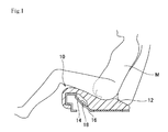
- FIG. 1 is an explanation drawing showing a working condition (installation condition) of a waist restraining airbag device according to an embodiment of the present invention, wherein the airbag is in a condition before development.
- a waist restraining airbag device 10 is disposed in or under a seat cushion 12 of a vehicle and adapted to restrain in an emergency (when a vehicle collision occurs) the waist of an occupant M sitting on the seat cushion 12 so as to limit occupant's forward movement.
- the airbag device 10 includes an airbag (inflatable bag) 14 arranged in an inflatable and expandable condition, with at least a part of its bottom surface (20a) fixed; and an inflator 18 for supplying inflation gas to the interior of the airbag 14.
- the airbag 14 may be made of a metal sheet having a thickness of about 0.4mm or a molded resin sheet having a thickness greater than the metal sheet.
- Fig. 2 is a side view illustrating a structure of the airbag device 10.
- the airbag 14 is expandable while being inclined in a forward direction of the vehicle from a vertical direction "V" to the bottom surface (20a).
- the inclined direction is indicated by "DO".
- a broken line 14b shows a conventional airbag with rectangle side surfaces in a developed state.
- a broken line 14a shows the airbag 14 with parallelogram side surfaces (22) in a developed state.
- the side faces of the airbag 14 are located at right and left ends of the airbag extending in a width direction (right and left direction) of the vehicle seat.
- a developing direction of the airbag 14 could be expressed by a direction parallel to left and right lines (front and rear direction to the occupant) of the parallelogram.
- Fig. 3 is a perspective view illustrating a structure of the airbag 14.
- the airbag 14 includes a main body 20 shaped to be tubular extending in a right and left direction of the vehicle (rolling up in front-back direction); and side face members 22, which close both side faces (right and left faces) of the main body 20.
- regions with short diagonal lines are welded. Namely, a region where ends of belt-shaped metal sheet, forming the tubular main body 20, are in contact with each other and a region where left and right sides of the main body 20 (ends of tubular) and the side face members 22 are in contact with each other are welded.
- Fig. 4 is a schematic view showing variation of shapes of the side faces of the airbag according to the embodiment, wherein (A) shows a state in the middle of folding process and (B) shows a state of developed.
- pressure is applied in a upper-lower direction, so that the offset projected portions are formed at front and rear sides.
- an upper large projected portion (22a) extends outwardly to form unevenness
- a lower large projected portion (22b) extends outwardly to form an unevenness.
- the side face member 22 of the airbag 14 is shaped to be almost parallelogram.
- the side face member would be a slightly-rounded parallelogram in an inflated and developed state according to a material strength or gas pressure of the airbag 14.
- a developing direction of the airbag 14 is shifted in a forward or backward direction of the vehicle without changing a location of the device 10 under the seat.
- the side face portion 22 is shaped to be about a parallelogram in a developed state, other shapes can be applied.
- an airbag 114 having an oval shape of side face can be employed instead.
- "D1" indicates a developing direction.
- the developing direction D1 could be expressed by a direction parallel to left and right side lines of a parallelogram (front and rear direction of the occupant), which is virtually formed to circumscribe the airbag 114 (side face) therein, so that the area of the parallelogram with a bottom line 20a is minimized.
- an airbag is developed in a direction inclined forwardly, the airbag could be designed to develop in a direction inclined cross wise or backwardly.
- a waist (pelvis) of an occupant could be restricted immediately after development of the airbag.
Landscapes
- Engineering & Computer Science (AREA)
- Aviation & Aerospace Engineering (AREA)
- Transportation (AREA)
- Mechanical Engineering (AREA)
- Air Bags (AREA)
- Seats For Vehicles (AREA)
Abstract
Description
- The present invention relates, for example, to an airbag device for a vehicle with a waist restraining function which restrains an occupant to a seat in an emergency to protect the occupant.
- When a forward collision of a vehicle is occurred, an occupant tends to be moved in a forward direction according to inertia. If the occupant fastens a seatbelt, forward movement of the occupant would be restrained to some extent by restraining function of a shoulder belt and a waist belt of a seat belt device. In order to secure the restraining of an occupant, a waist restraining device has been proposed (referring, for example, Patent
Related Document 1; Patent Related Document 2 and Patent Related Document 3), which uses technology limiting forward movement of an occupant by lifting a forward end of a seat cushion immediately when the vehicle is forward-crushed and is quickly decelerated. - [Patent Related Document 1]
JP H05-229378A
[Patent Related Document 2]JP H10-217818A
[Patent Related Document 3]GB 2357466 - According to conventional waist restraining devices, however, an occupant would get on an airbag, if an airbag (inflatable bag) is slightly delayed for development; and therefore, sufficient restraining performance could not be obtained. Further, according to a structural limitation under a seat cushion, an arrangement of an airbag is restricted; so that the airbag could not be located adjacent the waist of an occupant and therefore, it would be hard to restrain the occupant immediately.
- The present invention is made based on the above-described situation, and an object of the present invention is to provide a waist restraining airbag device which contributes to improvement in performance of restraining the waist of a vehicle occupant.
- In order to achieve the above-described object, a waist restraining airbag device according to the present invention is disposed in or under a seat cushion of a vehicle and adapted to restrain in an emergency the waist of an occupant sitting on the seat cushion so as to limit occupant's forward movement, wherein the airbag device includes an airbag arranged in an inflatable and expandable state, with at least a part of its bottom surface fixed; and a gas supply device for supplying inflation gas to the interior of the airbag. Further, the airbag is expandable while being inclined from a direction vertical to the bottom surface.
- Here, the angle of inclination of an airbag inflation includes forward and backward of the vehicle. If the developing direction of the airbag is inclined forwardly, an occupant would be prevented from getting on the airbag and sufficient restraining performance could be provided. On the other hand, if the developing direction of the airbag is inclined backwardly, it could be possible to restrict a waist (pelvis) of the occupant immediately after development of the airbag. In either case, it is not necessary to change arrangement of an airbag device under a seat cushion, where there is a plenty of arrangement limitations, and therefore, the airbag device could be applied to a variety of types of vehicles.
- In the above-described present invention, preferably, the airbag includes a main body shaped to be tubular extending in right and left direction of the vehicle; and side face members, which close both side faces (right and left faces) of the main body and are shaped to be parallelograms when the airbag is inflated. Further, the airbag may be folded offset in forward or backward direction of the vehicle between upper and lower portions.
- Fig. 1 is an explanation drawing showing a working condition (installation condition) of a waist restraining airbag device according to an embodiment of the present invention, wherein the airbag is in a condition before development. A waist
restraining airbag device 10, according to the embodiment, is disposed in or under aseat cushion 12 of a vehicle and adapted to restrain in an emergency (when a vehicle collision occurs) the waist of an occupant M sitting on theseat cushion 12 so as to limit occupant's forward movement. Theairbag device 10 includes an airbag (inflatable bag) 14 arranged in an inflatable and expandable condition, with at least a part of its bottom surface (20a) fixed; and aninflator 18 for supplying inflation gas to the interior of theairbag 14. Theairbag 14 may be made of a metal sheet having a thickness of about 0.4mm or a molded resin sheet having a thickness greater than the metal sheet. - Fig. 2 is a side view illustrating a structure of the
airbag device 10. As shown in Fig. 2, theairbag 14 is expandable while being inclined in a forward direction of the vehicle from a vertical direction "V" to the bottom surface (20a). The inclined direction is indicated by "DO". Abroken line 14b shows a conventional airbag with rectangle side surfaces in a developed state. Abroken line 14a shows theairbag 14 with parallelogram side surfaces (22) in a developed state. According to this embodiment, the side faces of theairbag 14 are located at right and left ends of the airbag extending in a width direction (right and left direction) of the vehicle seat. Further, if eachside face 22 of theairbag 14 in a developed state is almost parallelogram, a developing direction of theairbag 14 could be expressed by a direction parallel to left and right lines (front and rear direction to the occupant) of the parallelogram. - Fig. 3 is a perspective view illustrating a structure of the
airbag 14. Theairbag 14 includes amain body 20 shaped to be tubular extending in a right and left direction of the vehicle (rolling up in front-back direction); andside face members 22, which close both side faces (right and left faces) of themain body 20. In the drawing, regions with short diagonal lines are welded. Namely, a region where ends of belt-shaped metal sheet, forming the tubularmain body 20, are in contact with each other and a region where left and right sides of the main body 20 (ends of tubular) and theside face members 22 are in contact with each other are welded. Theairbag 14 in a non-developed and accommodated state is folded to be offset (uneven) in forward or backward direction of the vehicle between upper and lower portions, as shown in Figs. 2 and 3. Theside face member 22 of theairbag 14 in a state before folding includes a projectedportion 22a extending in a forward direction of the vehicle and a projectedportion 22b extending in a backward direction of the vehicle. The projectedportions - Fig. 4 is a schematic view showing variation of shapes of the side faces of the airbag according to the embodiment, wherein (A) shows a state in the middle of folding process and (B) shows a state of developed. When folding the
airbag 14, as shown in the drawing (A), pressure is applied in a upper-lower direction, so that the offset projected portions are formed at front and rear sides. At the front side, an upper large projected portion (22a) extends outwardly to form unevenness, while at the rear side, a lower large projected portion (22b) extends outwardly to form an unevenness. In a developed state, as shown in Fig. 4 (B), theside face member 22 of theairbag 14 is shaped to be almost parallelogram. Here, the side face member would be a slightly-rounded parallelogram in an inflated and developed state according to a material strength or gas pressure of theairbag 14. - An important point of this embodiment is that a developing direction of the
airbag 14 is shifted in a forward or backward direction of the vehicle without changing a location of thedevice 10 under the seat. In order to achieve this, although theside face portion 22 is shaped to be about a parallelogram in a developed state, other shapes can be applied. For example, as shown in Fig. 5, anairbag 114 having an oval shape of side face can be employed instead. In the drawing, "D1" indicates a developing direction. In this case, the developing direction D1 could be expressed by a direction parallel to left and right side lines of a parallelogram (front and rear direction of the occupant), which is virtually formed to circumscribe the airbag 114 (side face) therein, so that the area of the parallelogram with abottom line 20a is minimized. - Fig. 4 is an explanation drawing showing a working condition (installation condition) of the waist
restraining airbag device 10 according to the embodiment, wherein the airbag is in a condition of developed. When the vehicle is forward-crushed and is quickly decelerated, theinflator 18 works and a high-pressured gas is supplied from theinflator 18 into theairbag 14. When the high-pressured gas is filled in the airbag, theairbag 14 is inflated and developed and pushing theseat cushion 12 upwardly, as shown in Fig. 4. - As described above, according to the present embodiment, the
airbag 14 is developed in a direction inclined forwardly, so that it is prevented that an occupant get on theairbag 14, and therefore, sufficient restraining performance to the occupant M could be obtained. Further, even in a situation in that many of structural limitations exist under a seat cushion, it is not necessary to change a location of theairbag device 10, and therefore, the device is applicable to a variety of types of vehicles. - Although an embodiment of the present invention is described, the present invention is not limited by the embodiment, and could be changed within a technical scope described in the claims. Although, according to the above described embodiment, an airbag is developed in a direction inclined forwardly, the airbag could be designed to develop in a direction inclined cross wise or backwardly. When an airbag is designed to develop in a direction inclined backwardly, a waist (pelvis) of an occupant could be restricted immediately after development of the airbag. In either case, it is not necessary to change arrangement of an airbag device under a seat cushion, where there is a plenty of arrangement limitations, and therefore, the airbag device could be applied to a variety types of vehicles.
-
- [Fig. 1] Fig. 1 is an explanation drawing showing a working condition (installation condition) of a waist restraining airbag device according to an embodiment of the present invention, wherein the airbag is in a condition before development.
- [Fig. 2] Fig. 2 is a side view illustrating a structure of the airbag device according to the embodiment.
- [Fig. 3] Fig. 3 is a perspective view illustrating a structure of the airbag device according to the embodiment.
- [Fig. 4] Fig. 4 is a schematic view showing variation of shapes of side faces of the airbag according to the embodiment, wherein (A) shows a state in the middle of folding process and (B) shows a state of developed.
- [Fig. 5] Fig. 5 is an explanation drawing showing a working condition (installation condition) of the waist restraining airbag device according to the embodiment, wherein the airbag is in a condition of developed.
- [Fig. 6] Fig. 6 is a schematic view showing an airbag in a developed state (side face portion) used for an airbag device according to another embodiment of the present invention.
-
- 10
- Waist Restraining Airbag Device
- 12
- Seat Cushion
- 14, 114
- Airbag
- 16
- Fitting Member
- 18
- Inflator
- 20
- Main Body
- 20a
- Bottom Face of Main Body
- 22
- Side Face Portion
- D0, D1
- Developing Direction
- V
- Vertical Direction
Claims (5)
- A waist restraining airbag device, disposed in or under a seat cushion of a vehicle and adapted to restrain in an emergency the waist of an occupant sitting on the seat cushion so as to limit occupant's forward movement, which is characterized by comprising:an airbag arranged in an inflatable and expandable state, with at least a part of its bottom surface fixed; anda gas supply device for supplying inflation gas to the interior of the airbag, whereinthe airbag is expandable while being inclined from a direction vertical to the bottom surface.
- An airbag device, according to claim 1, wherein
the airbag comprises a main body shaped to be tubular extending in right and left direction of the vehicle; and side face members, which close both side faces (right and left faces) of the main body and are shaped to be parallelograms when the airbag is inflated. - An airbag device, according to claim 2, wherein
the airbag is folded offset in forward or backward direction of the vehicle between upper and lower portions. - An airbag device, according to claim 1, 2 or 3, wherein
the airbag is made of a metal shaped to be thin board. - A seat cushion device for vehicle, provided with an airbag device according to claim 1, 2, 3 or 4, which is characterized by comprising:a seat frame to which a bottom surface of the airbag is fixed.
Applications Claiming Priority (2)
| Application Number | Priority Date | Filing Date | Title |
|---|---|---|---|
| JP2004195464 | 2004-07-01 | ||
| PCT/JP2005/007512 WO2006003749A1 (en) | 2004-07-01 | 2005-04-20 | Waist restraining airbag device and seat cushion device using the same |
Publications (3)
| Publication Number | Publication Date |
|---|---|
| EP1767396A1 true EP1767396A1 (en) | 2007-03-28 |
| EP1767396A4 EP1767396A4 (en) | 2008-11-05 |
| EP1767396B1 EP1767396B1 (en) | 2011-09-21 |
Family
ID=35782564
Family Applications (1)
| Application Number | Title | Priority Date | Filing Date |
|---|---|---|---|
| EP05734644A Expired - Lifetime EP1767396B1 (en) | 2004-07-01 | 2005-04-20 | Waist restraining airbag device and seat cushion device using the same |
Country Status (4)
| Country | Link |
|---|---|
| EP (1) | EP1767396B1 (en) |
| JP (1) | JP4709153B2 (en) |
| AT (1) | ATE525241T1 (en) |
| WO (1) | WO2006003749A1 (en) |
Cited By (5)
| Publication number | Priority date | Publication date | Assignee | Title |
|---|---|---|---|---|
| US8702121B2 (en) | 2010-05-14 | 2014-04-22 | Ashimori Industry Co., Ltd. | Airbag device |
| US9889937B2 (en) | 2012-03-19 | 2018-02-13 | Amsafe, Inc. | Structure mounted airbag assemblies and associated systems and methods |
| US9925950B2 (en) | 2015-04-11 | 2018-03-27 | Amsafe, Inc. | Active airbag vent system |
| US9944245B2 (en) | 2015-03-28 | 2018-04-17 | Amsafe, Inc. | Extending pass-through airbag occupant restraint systems, and associated systems and methods |
| US10604259B2 (en) | 2016-01-20 | 2020-03-31 | Amsafe, Inc. | Occupant restraint systems having extending restraints, and associated systems and methods |
Families Citing this family (6)
| Publication number | Priority date | Publication date | Assignee | Title |
|---|---|---|---|---|
| JP2007320543A (en) * | 2006-06-05 | 2007-12-13 | Autoliv Development Ab | Vehicle seat cushion airbag device |
| JP5687892B2 (en) * | 2010-12-13 | 2015-03-25 | 芦森工業株式会社 | Airbag device |
| JP6620933B2 (en) * | 2016-01-21 | 2019-12-18 | スズキ株式会社 | Seat cushion airbag device |
| JP7411807B2 (en) * | 2020-07-14 | 2024-01-11 | オートリブ ディベロップメント エービー | Occupant protection device |
| KR20240050089A (en) * | 2022-10-11 | 2024-04-18 | 현대모비스 주식회사 | Seat cushion airbag and folding method of the seat cushion airbag |
| DE102023130117A1 (en) * | 2023-10-31 | 2025-04-30 | Bayerische Motoren Werke Aktiengesellschaft | Vehicle seat with an accident-dependent seat cushion airbag |
Family Cites Families (6)
| Publication number | Priority date | Publication date | Assignee | Title |
|---|---|---|---|---|
| GB2357466B (en) * | 1999-12-21 | 2003-04-02 | Autoliv Dev | Improvements in or relating to a vehicle seat |
| JP4239387B2 (en) * | 2000-09-06 | 2009-03-18 | 豊田合成株式会社 | Vehicle seat |
| GB2385028A (en) * | 2002-02-12 | 2003-08-13 | Autoliv Dev | An inflatable safety arrangement |
| JP3972736B2 (en) * | 2002-06-04 | 2007-09-05 | タカタ株式会社 | Crew protection device |
| JP3936654B2 (en) * | 2002-11-22 | 2007-06-27 | オートリブ・ジャパン株式会社 | Inflator bag and inflator bag module for passenger restraint device |
| DE10320967A1 (en) * | 2003-05-09 | 2004-11-25 | Trw Occupant Restraint Systems Gmbh & Co. Kg | Inflatable seat restraint cushion |
-
2005
- 2005-04-20 WO PCT/JP2005/007512 patent/WO2006003749A1/en not_active Ceased
- 2005-04-20 JP JP2006528373A patent/JP4709153B2/en not_active Expired - Fee Related
- 2005-04-20 AT AT05734644T patent/ATE525241T1/en not_active IP Right Cessation
- 2005-04-20 EP EP05734644A patent/EP1767396B1/en not_active Expired - Lifetime
Cited By (5)
| Publication number | Priority date | Publication date | Assignee | Title |
|---|---|---|---|---|
| US8702121B2 (en) | 2010-05-14 | 2014-04-22 | Ashimori Industry Co., Ltd. | Airbag device |
| US9889937B2 (en) | 2012-03-19 | 2018-02-13 | Amsafe, Inc. | Structure mounted airbag assemblies and associated systems and methods |
| US9944245B2 (en) | 2015-03-28 | 2018-04-17 | Amsafe, Inc. | Extending pass-through airbag occupant restraint systems, and associated systems and methods |
| US9925950B2 (en) | 2015-04-11 | 2018-03-27 | Amsafe, Inc. | Active airbag vent system |
| US10604259B2 (en) | 2016-01-20 | 2020-03-31 | Amsafe, Inc. | Occupant restraint systems having extending restraints, and associated systems and methods |
Also Published As
| Publication number | Publication date |
|---|---|
| JPWO2006003749A1 (en) | 2008-04-17 |
| EP1767396B1 (en) | 2011-09-21 |
| WO2006003749A1 (en) | 2006-01-12 |
| ATE525241T1 (en) | 2011-10-15 |
| EP1767396A4 (en) | 2008-11-05 |
| JP4709153B2 (en) | 2011-06-22 |
Similar Documents
| Publication | Publication Date | Title |
|---|---|---|
| EP1369314B1 (en) | Occupant protection apparatus | |
| US10800368B2 (en) | Vehicle occupant protection device, airbag control method, and airbag folding method | |
| EP1369315B1 (en) | Occupant protecting device in vehicle seat | |
| US6752454B2 (en) | Vehicle seat | |
| EP4035954B1 (en) | Airbag device and vehicle seat | |
| JP6926959B2 (en) | Vehicle seat | |
| EP1422104B1 (en) | Occupant protection system | |
| EP3708438B1 (en) | Airbag and occupant restraint device | |
| KR20200043122A (en) | Airbag for table of vehicles | |
| EP3922517B1 (en) | Side airbag device | |
| EP1767396B1 (en) | Waist restraining airbag device and seat cushion device using the same | |
| CN110053526B (en) | Vehicle seat | |
| KR102693029B1 (en) | Roof airbag apparatus | |
| JP2001239872A (en) | Occupant crash protection device | |
| JP2008195202A (en) | Vehicular seat | |
| JP7381772B2 (en) | Seat built-in airbag device | |
| JP4165217B2 (en) | Crew protection device | |
| JP2005145227A (en) | Occupant protector | |
| JP2004148975A (en) | Protection device for occupant | |
| EP2078645B1 (en) | Airbag device for restraining waist part | |
| JP7803289B2 (en) | Vehicle occupant restraint structure | |
| KR102803059B1 (en) | Passenger protection apparatus for vehicle | |
| KR102803050B1 (en) | Passenger protection apparatus for vehicle | |
| EP4549257A1 (en) | Side airbag device | |
| KR20250159221A (en) | Rear seat occupant protection device |
Legal Events
| Date | Code | Title | Description |
|---|---|---|---|
| PUAI | Public reference made under article 153(3) epc to a published international application that has entered the european phase |
Free format text: ORIGINAL CODE: 0009012 |
|
| 17P | Request for examination filed |
Effective date: 20070111 |
|
| AK | Designated contracting states |
Kind code of ref document: A1 Designated state(s): AT BE BG CH CY CZ DE DK EE ES FI FR GB GR HU IE IS IT LI LT LU MC NL PL PT RO SE SI SK TR |
|
| DAX | Request for extension of the european patent (deleted) | ||
| A4 | Supplementary search report drawn up and despatched |
Effective date: 20081007 |
|
| 17Q | First examination report despatched |
Effective date: 20090409 |
|
| GRAP | Despatch of communication of intention to grant a patent |
Free format text: ORIGINAL CODE: EPIDOSNIGR1 |
|
| GRAS | Grant fee paid |
Free format text: ORIGINAL CODE: EPIDOSNIGR3 |
|
| GRAA | (expected) grant |
Free format text: ORIGINAL CODE: 0009210 |
|
| AK | Designated contracting states |
Kind code of ref document: B1 Designated state(s): AT BE BG CH CY CZ DE DK EE ES FI FR GB GR HU IE IS IT LI LT LU MC NL PL PT RO SE SI SK TR |
|
| REG | Reference to a national code |
Ref country code: GB Ref legal event code: FG4D |
|
| REG | Reference to a national code |
Ref country code: CH Ref legal event code: EP |
|
| REG | Reference to a national code |
Ref country code: IE Ref legal event code: FG4D |
|
| REG | Reference to a national code |
Ref country code: DE Ref legal event code: R096 Ref document number: 602005030130 Country of ref document: DE Effective date: 20111208 |
|
| REG | Reference to a national code |
Ref country code: NL Ref legal event code: VDEP Effective date: 20110921 |
|
| PG25 | Lapsed in a contracting state [announced via postgrant information from national office to epo] |
Ref country code: FI Free format text: LAPSE BECAUSE OF FAILURE TO SUBMIT A TRANSLATION OF THE DESCRIPTION OR TO PAY THE FEE WITHIN THE PRESCRIBED TIME-LIMIT Effective date: 20110921 Ref country code: LT Free format text: LAPSE BECAUSE OF FAILURE TO SUBMIT A TRANSLATION OF THE DESCRIPTION OR TO PAY THE FEE WITHIN THE PRESCRIBED TIME-LIMIT Effective date: 20110921 Ref country code: SE Free format text: LAPSE BECAUSE OF FAILURE TO SUBMIT A TRANSLATION OF THE DESCRIPTION OR TO PAY THE FEE WITHIN THE PRESCRIBED TIME-LIMIT Effective date: 20110921 |
|
| LTIE | Lt: invalidation of european patent or patent extension |
Effective date: 20110921 |
|
| PG25 | Lapsed in a contracting state [announced via postgrant information from national office to epo] |
Ref country code: GR Free format text: LAPSE BECAUSE OF FAILURE TO SUBMIT A TRANSLATION OF THE DESCRIPTION OR TO PAY THE FEE WITHIN THE PRESCRIBED TIME-LIMIT Effective date: 20111222 Ref country code: SI Free format text: LAPSE BECAUSE OF FAILURE TO SUBMIT A TRANSLATION OF THE DESCRIPTION OR TO PAY THE FEE WITHIN THE PRESCRIBED TIME-LIMIT Effective date: 20110921 Ref country code: CY Free format text: LAPSE BECAUSE OF FAILURE TO SUBMIT A TRANSLATION OF THE DESCRIPTION OR TO PAY THE FEE WITHIN THE PRESCRIBED TIME-LIMIT Effective date: 20110921 Ref country code: AT Free format text: LAPSE BECAUSE OF FAILURE TO SUBMIT A TRANSLATION OF THE DESCRIPTION OR TO PAY THE FEE WITHIN THE PRESCRIBED TIME-LIMIT Effective date: 20110921 |
|
| REG | Reference to a national code |
Ref country code: AT Ref legal event code: MK05 Ref document number: 525241 Country of ref document: AT Kind code of ref document: T Effective date: 20110921 |
|
| PG25 | Lapsed in a contracting state [announced via postgrant information from national office to epo] |
Ref country code: BE Free format text: LAPSE BECAUSE OF FAILURE TO SUBMIT A TRANSLATION OF THE DESCRIPTION OR TO PAY THE FEE WITHIN THE PRESCRIBED TIME-LIMIT Effective date: 20110921 |
|
| PG25 | Lapsed in a contracting state [announced via postgrant information from national office to epo] |
Ref country code: SK Free format text: LAPSE BECAUSE OF FAILURE TO SUBMIT A TRANSLATION OF THE DESCRIPTION OR TO PAY THE FEE WITHIN THE PRESCRIBED TIME-LIMIT Effective date: 20110921 Ref country code: IS Free format text: LAPSE BECAUSE OF FAILURE TO SUBMIT A TRANSLATION OF THE DESCRIPTION OR TO PAY THE FEE WITHIN THE PRESCRIBED TIME-LIMIT Effective date: 20120121 Ref country code: CZ Free format text: LAPSE BECAUSE OF FAILURE TO SUBMIT A TRANSLATION OF THE DESCRIPTION OR TO PAY THE FEE WITHIN THE PRESCRIBED TIME-LIMIT Effective date: 20110921 |
|
| PGFP | Annual fee paid to national office [announced via postgrant information from national office to epo] |
Ref country code: FR Payment date: 20120223 Year of fee payment: 8 |
|
| PG25 | Lapsed in a contracting state [announced via postgrant information from national office to epo] |
Ref country code: RO Free format text: LAPSE BECAUSE OF FAILURE TO SUBMIT A TRANSLATION OF THE DESCRIPTION OR TO PAY THE FEE WITHIN THE PRESCRIBED TIME-LIMIT Effective date: 20110921 Ref country code: PL Free format text: LAPSE BECAUSE OF FAILURE TO SUBMIT A TRANSLATION OF THE DESCRIPTION OR TO PAY THE FEE WITHIN THE PRESCRIBED TIME-LIMIT Effective date: 20110921 Ref country code: PT Free format text: LAPSE BECAUSE OF FAILURE TO SUBMIT A TRANSLATION OF THE DESCRIPTION OR TO PAY THE FEE WITHIN THE PRESCRIBED TIME-LIMIT Effective date: 20120123 Ref country code: IT Free format text: LAPSE BECAUSE OF FAILURE TO SUBMIT A TRANSLATION OF THE DESCRIPTION OR TO PAY THE FEE WITHIN THE PRESCRIBED TIME-LIMIT Effective date: 20110921 Ref country code: NL Free format text: LAPSE BECAUSE OF FAILURE TO SUBMIT A TRANSLATION OF THE DESCRIPTION OR TO PAY THE FEE WITHIN THE PRESCRIBED TIME-LIMIT Effective date: 20110921 Ref country code: EE Free format text: LAPSE BECAUSE OF FAILURE TO SUBMIT A TRANSLATION OF THE DESCRIPTION OR TO PAY THE FEE WITHIN THE PRESCRIBED TIME-LIMIT Effective date: 20110921 |
|
| PLBE | No opposition filed within time limit |
Free format text: ORIGINAL CODE: 0009261 |
|
| STAA | Information on the status of an ep patent application or granted ep patent |
Free format text: STATUS: NO OPPOSITION FILED WITHIN TIME LIMIT |
|
| PG25 | Lapsed in a contracting state [announced via postgrant information from national office to epo] |
Ref country code: DK Free format text: LAPSE BECAUSE OF FAILURE TO SUBMIT A TRANSLATION OF THE DESCRIPTION OR TO PAY THE FEE WITHIN THE PRESCRIBED TIME-LIMIT Effective date: 20110921 |
|
| PGFP | Annual fee paid to national office [announced via postgrant information from national office to epo] |
Ref country code: DE Payment date: 20120208 Year of fee payment: 8 |
|
| 26N | No opposition filed |
Effective date: 20120622 |
|
| REG | Reference to a national code |
Ref country code: DE Ref legal event code: R097 Ref document number: 602005030130 Country of ref document: DE Effective date: 20120622 |
|
| PG25 | Lapsed in a contracting state [announced via postgrant information from national office to epo] |
Ref country code: MC Free format text: LAPSE BECAUSE OF NON-PAYMENT OF DUE FEES Effective date: 20120430 |
|
| REG | Reference to a national code |
Ref country code: CH Ref legal event code: PL |
|
| GBPC | Gb: european patent ceased through non-payment of renewal fee |
Effective date: 20120420 |
|
| REG | Reference to a national code |
Ref country code: IE Ref legal event code: MM4A |
|
| PG25 | Lapsed in a contracting state [announced via postgrant information from national office to epo] |
Ref country code: LI Free format text: LAPSE BECAUSE OF NON-PAYMENT OF DUE FEES Effective date: 20120430 Ref country code: IE Free format text: LAPSE BECAUSE OF NON-PAYMENT OF DUE FEES Effective date: 20120420 Ref country code: GB Free format text: LAPSE BECAUSE OF NON-PAYMENT OF DUE FEES Effective date: 20120420 Ref country code: CH Free format text: LAPSE BECAUSE OF NON-PAYMENT OF DUE FEES Effective date: 20120430 |
|
| PG25 | Lapsed in a contracting state [announced via postgrant information from national office to epo] |
Ref country code: BG Free format text: LAPSE BECAUSE OF FAILURE TO SUBMIT A TRANSLATION OF THE DESCRIPTION OR TO PAY THE FEE WITHIN THE PRESCRIBED TIME-LIMIT Effective date: 20111221 |
|
| PG25 | Lapsed in a contracting state [announced via postgrant information from national office to epo] |
Ref country code: ES Free format text: LAPSE BECAUSE OF FAILURE TO SUBMIT A TRANSLATION OF THE DESCRIPTION OR TO PAY THE FEE WITHIN THE PRESCRIBED TIME-LIMIT Effective date: 20120101 |
|
| PG25 | Lapsed in a contracting state [announced via postgrant information from national office to epo] |
Ref country code: DE Free format text: LAPSE BECAUSE OF NON-PAYMENT OF DUE FEES Effective date: 20131101 |
|
| REG | Reference to a national code |
Ref country code: FR Ref legal event code: ST Effective date: 20131231 |
|
| REG | Reference to a national code |
Ref country code: DE Ref legal event code: R119 Ref document number: 602005030130 Country of ref document: DE Effective date: 20131101 |
|
| PG25 | Lapsed in a contracting state [announced via postgrant information from national office to epo] |
Ref country code: FR Free format text: LAPSE BECAUSE OF NON-PAYMENT OF DUE FEES Effective date: 20130430 |
|
| PG25 | Lapsed in a contracting state [announced via postgrant information from national office to epo] |
Ref country code: TR Free format text: LAPSE BECAUSE OF FAILURE TO SUBMIT A TRANSLATION OF THE DESCRIPTION OR TO PAY THE FEE WITHIN THE PRESCRIBED TIME-LIMIT Effective date: 20110921 |
|
| PG25 | Lapsed in a contracting state [announced via postgrant information from national office to epo] |
Ref country code: LU Free format text: LAPSE BECAUSE OF NON-PAYMENT OF DUE FEES Effective date: 20120420 |
|
| PG25 | Lapsed in a contracting state [announced via postgrant information from national office to epo] |
Ref country code: HU Free format text: LAPSE BECAUSE OF FAILURE TO SUBMIT A TRANSLATION OF THE DESCRIPTION OR TO PAY THE FEE WITHIN THE PRESCRIBED TIME-LIMIT Effective date: 20050420 |