EP1766186B1 - Method and system for collaring - Google Patents
Method and system for collaring Download PDFInfo
- Publication number
- EP1766186B1 EP1766186B1 EP05746886A EP05746886A EP1766186B1 EP 1766186 B1 EP1766186 B1 EP 1766186B1 EP 05746886 A EP05746886 A EP 05746886A EP 05746886 A EP05746886 A EP 05746886A EP 1766186 B1 EP1766186 B1 EP 1766186B1
- Authority
- EP
- European Patent Office
- Prior art keywords
- drilling
- pressure
- percussion
- collaring
- controlling
- Prior art date
- Legal status (The legal status is an assumption and is not a legal conclusion. Google has not performed a legal analysis and makes no representation as to the accuracy of the status listed.)
- Expired - Lifetime
Links
Images

Classifications
-
- E—FIXED CONSTRUCTIONS
- E21—EARTH OR ROCK DRILLING; MINING
- E21B—EARTH OR ROCK DRILLING; OBTAINING OIL, GAS, WATER, SOLUBLE OR MELTABLE MATERIALS OR A SLURRY OF MINERALS FROM WELLS
- E21B44/00—Automatic control systems specially adapted for drilling operations, i.e. self-operating systems which function to carry out or modify a drilling operation without intervention of a human operator, e.g. computer-controlled drilling systems; Systems specially adapted for monitoring a plurality of drilling variables or conditions
- E21B44/02—Automatic control of the tool feed
- E21B44/06—Automatic control of the tool feed in response to the flow or pressure of the motive fluid of the drive
-
- E—FIXED CONSTRUCTIONS
- E21—EARTH OR ROCK DRILLING; MINING
- E21B—EARTH OR ROCK DRILLING; OBTAINING OIL, GAS, WATER, SOLUBLE OR MELTABLE MATERIALS OR A SLURRY OF MINERALS FROM WELLS
- E21B44/00—Automatic control systems specially adapted for drilling operations, i.e. self-operating systems which function to carry out or modify a drilling operation without intervention of a human operator, e.g. computer-controlled drilling systems; Systems specially adapted for monitoring a plurality of drilling variables or conditions
- E21B44/02—Automatic control of the tool feed
- E21B44/08—Automatic control of the tool feed in response to the amplitude of the movement of the percussion tool, e.g. jump or recoil
Definitions
- the present invention relates to a method and system for controlling drilling parameters during an initial phase of drilling into a rock.
- the critical part of the drilling i.e. the start-up or so called collaring
- the critical part of the drilling should be smooth and careful until there has been formed a deep enough hole having a correct direction, whereafter full feed force and drilling power may be utilized. What constitutes a deep enough depth depends to a large part on the quality of the rock. For example, soft rocks having many cracks may require a deeper hole to ensure a correct direction, before full feed force is used.
- the transition step should be smooth, but not unnecessary extended in order to avoid that time is lost because a great part of the hole is drilled at a lower power than the available full power. Consequently, the parameters that have to be set constitutes a considerable drawback of the method shown in EP 0 564 504 .
- discontinuities in the direction of drilling parameter increase may give incorrect information to those parts of the automatic control system that supervise these parameters in order to detect a drill possibly getting stuck.
- the above mentioned objects are accomplished by a method for controlling drilling parameters during an initial phase of drilling in rock using a drilling machine, whereby the percussion pressure and feed pressure of the drilling machine are controlled as continuously increasing functions during the initial phase.
- the number of parameters can be minimised to include start values for the percussion and feed pressure, and time duration of the initial phase. Further, a successful drilling is ensured by adjusting the collaring depth by means of the duration of the initial phase.
- the initial phase thus includes a single stage control starting from predetermined start values to full force values. This results in a time efficient initial drilling, wherein the time to set different parameters in a plurality of different stages has been eliminated.
- control is represented by functions, which are continuous in time and having a gradually increasing derivative.
- said continuous functions are represented by exponential functions.
- the feed pressure is supervised during the collaring stage, so that the percussion pressure is limited if the damping pressure with certainty does not exceed the idling pressure of the damper.
- This supervision may, for example, be performed by means of a RPCF function (Rotation Pressure Controlled Feed), and the percussion pressure values may, in a preferred embodiment, be limited to the percussion pressure start values.
- the percussion pressure may be lowered when the feed pressure goes below a predetermined level.
- the present invention is also related to such a system, by means of which advantages similar to the above described is achieved.
- This method comprises a number of parameters that has to be set. Initial values have to be determined, and, also, for how long this stage with reduced power is to go on. Further, the aspects of the transition stage illustrated in figure 2, between the points T1 and T2, have to be determined. In other words, it has to be determined what the transition step should look like in order for it to be smooth enough. At the same time it is undesired to drill with the reduced power too long, since time then is lost.
- start values for the percussion pressure of the drilling machine (and thereby the percussion power of the drilling machine), and the feed pressure are chosen. These values are chosen such that the collaring is smooth enough to ensure that the hole obtains correct direction and position, while at the same time the pressure cannot be so low that it may cause problems in the drilling machine.
- start values are advantageously chosen to be slightly higher than the accumulator pressure in order to avoid problems with included membranes.
- the start values should, off course, neither be too low to accomplish a collaring hole.
- the start values may, for example, in an ordinary drilling machine, be about 130 bar.
- the initial phase, or collaring phase is then controlled by continuously increasing functions.
- the continuously increasing functions have a gradually increasing derivative, as is shown in figure 3, which results in the preferred, smooth transition.
- a function which advantageously may be used, is the mathematically well known exponential function, but any substantially continuous function in accordance with the mentioned requirements may be used.
- the use of a continuous function of time with a gradually increasing derivative results in a system with only two control stages, of which the parameters of the first stage, the collaring, includes the start values of the percussion pressure, the feed pressure and the length of the initial stage. Thereby, the number of parameters needed to be set is minimised.
- the percussion pressure and feed pressure are controlled independently, but with the same duration, i.e. throughout the collaring stage.
- the feed pressure should, however, be supervised by means of the system RPCF function (Rotation Pressure Controlled Feed) during the collaring stage.
- the RPCF function controls the feed pressure such that the rotation pressure and/or torque is substantially constant in order to ensure that the drill string component joints are suitably tightened. This function is of particular importance during full drilling, when the power is higher.
- the damping pressure of the drilling machine should be supervised so that the percussion pressure is limited to, for example, the start values if the damping pressure with certainty does not exceed the no-load pressure of the damper.
- the damper is used to damp the reflexions which arise when the drill steel hits the rock.
- the damping pressure may be used to ensure that the drill steel is in contact with the rock at time of percussion.
- the initial stage may, in other words, be combined with the supervision of the damping pressure so that the percussion pressure does not run away from the feed pressure.
- the percussion pressure may be lowered when the feed pressure is or goes below a predetermined level.
- An operator may chose between the setting of a desired hole depth of the collaring, or for how long the initial phase should go on.
- stop values may also be determined, which advantageously correspond to the full power of the drilling machine. It may, however, in some situations, be necessary to run the machine at a reduced power, whereby desired values may be set.
- FIG 4 schematically shows a system 1, in which the present invention may be utilised.
- the system 1 includes, in its simplest embodiment, a drilling machine 2 with a control system 3, by means of which an operator may control the system 1.
- the control system may be integrated with the drilling machine 2, or be separately connected.
Landscapes
- Geology (AREA)
- Life Sciences & Earth Sciences (AREA)
- Engineering & Computer Science (AREA)
- Mining & Mineral Resources (AREA)
- Environmental & Geological Engineering (AREA)
- Fluid Mechanics (AREA)
- Physics & Mathematics (AREA)
- General Life Sciences & Earth Sciences (AREA)
- Geochemistry & Mineralogy (AREA)
- Earth Drilling (AREA)
- Paper (AREA)
- Diaphragms For Electromechanical Transducers (AREA)
- Medicines That Contain Protein Lipid Enzymes And Other Medicines (AREA)
- Peptides Or Proteins (AREA)
Abstract
Description
- The present invention relates to a method and system for controlling drilling parameters during an initial phase of drilling into a rock.
- When drilling, it is very important that the start-up is performed in a correct manner. Thus, at the start-up of drilling into rocks with a percussion rock drilling machine, it has to be ensured that the first part of the hole is accurately accomplished in order for the hole to be positioned at an intended place and have a correct direction.
- In order to obtain a good start of the drilling, it is desired to try to control the drilling steel as good as possible near the drill bit at the beginning of the drilling (drill steel support), as well as to drill the first part of the hole using a reduced feed force and a reduced drilling power in order to prevent the drilling steel from sliding against the surface of the rock. In other words, the critical part of the drilling, i.e. the start-up or so called collaring, should be smooth and careful until there has been formed a deep enough hole having a correct direction, whereafter full feed force and drilling power may be utilized. What constitutes a deep enough depth depends to a large part on the quality of the rock. For example, soft rocks having many cracks may require a deeper hole to ensure a correct direction, before full feed force is used.
- When the use of hydraulic rock drilling machines at first started, generally, these were powered by uncomplicated direct controlled hydraulic systems. The collaring was realized by starting the drilling at a reduced hydraulic pressure supply to the percussion circuit and feed drive of the drilling machine. After a certain time, or when a certain drilled hole depth is reached, the pressures were increased to such values that resulted in a desired balance between drilling speed and working life of the drilling steel (full drilling). This pressure increase was performed by adjusting sequence valves, and the pressure increase process depended on the valves and ducts in the hydraulic system.
- When more modern electrically and computer controlled hydraulic systems later have come in use, the process of an initial drilling step has been maintained, in which a reduced drilling machine power and feed force is used, and a final drilling step where full power is utilised. A suitable transition occurs there between.
- An example of such a previously known method for controlling drilling parameters is shown in the
European patent EP 0 564 504 . This publication discloses a method for controlling a rock drilling process, and in accordance with the method described therein the percussion force and feed force of a drilling machine are adjusted, so that the rotational power of the drill does not exceed a pre-set limit value. - This is done by controlling the drilling in at least three different stages, of which the first stage constitutes the start-up drilling, the second a transition stage to the third, which in turn is the normal operation. According to the method, suitable values for each drilling stage are to be set, so that the percussion force and feed force are optimal for each stage.
- There are several drawbacks with the method described in
EP 0 564 504 . An obvious drawback is that it is not always known in advance what is optimal for a certain stage, and it is not evident from said document how the predetermined feed force and percussion force values for the respective stage are to be determined in order to be optimal. Another drawback is that the process with three or more stages in the control program is unnecessarily complicated, since, among other things, it has to be determined, on the one hand, how long the first reduced stage is to go on, and, on the other hand, what the transition stage should look like. - The transition step should be smooth, but not unnecessary extended in order to avoid that time is lost because a great part of the hole is drilled at a lower power than the available full power. Consequently, the parameters that have to be set constitutes a considerable drawback of the method shown in
EP 0 564 504 . There are a number of parameters to adjust for each of the three or more stages, for example, different periods of time, percussion force, feed force, drilling time, drilling depth, speeds etc. Moreover, discontinuities in the direction of drilling parameter increase may give incorrect information to those parts of the automatic control system that supervise these parameters in order to detect a drill possibly getting stuck. - An example of a previously known method for controlling drilling parameters is shown in
WO 95/28549 - It would thus be desirable to provide a method and an apparatus that simplifies and improves the initial phase of drilling in rock.
- It is an object of the present invention to provide a method and a system that solves the above problems. More specifically, it is an object of the present invention to provide an improved method and a system for controlling drilling parameters during collaring, in which the time consumption can be minimised, as well as the number of parameters that have to be set. Another object of the present invention is to provide a method and a system for controlling drilling parameters during collaring, which ensures that the collaring hole obtains the intended direction and position.
- These and other objects are achieved according to the present invention by a method for controlling drilling parameters in an initial phase, as claimed in claim 1, and according to a system as claimed in claim 6.
- According to the present invention, the above mentioned objects are accomplished by a method for controlling drilling parameters during an initial phase of drilling in rock using a drilling machine, whereby the percussion pressure and feed pressure of the drilling machine are controlled as continuously increasing functions during the initial phase.
- Thereby, the number of parameters can be minimised to include start values for the percussion and feed pressure, and time duration of the initial phase. Further, a successful drilling is ensured by adjusting the collaring depth by means of the duration of the initial phase.
- According to the present invention, the initial phase thus includes a single stage control starting from predetermined start values to full force values. This results in a time efficient initial drilling, wherein the time to set different parameters in a plurality of different stages has been eliminated.
- According to one embodiment of the present invention, the control is represented by functions, which are continuous in time and having a gradually increasing derivative. Thereby, a continuously increasing pressure is obtained, whereby the initial phase results in a collaring hole with a correct direction, whereby the risk of drilling steel slip is minimised.
- According to another embodiment of the present invention, said continuous functions are represented by exponential functions.
- In this way, a well known mathematic function may be used, which can easily be programmed and stored.
- According to another embodiment of the present invention, the feed pressure is supervised during the collaring stage, so that the percussion pressure is limited if the damping pressure with certainty does not exceed the idling pressure of the damper. Thereby, it is ensured that the percussion pressure of the drilling machine is limited when the drilling steel shank is not in percussion position. This supervision may, for example, be performed by means of a RPCF function (Rotation Pressure Controlled Feed), and the percussion pressure values may, in a preferred embodiment, be limited to the percussion pressure start values. Alternatively, the percussion pressure may be lowered when the feed pressure goes below a predetermined level.
- The present invention is also related to such a system, by means of which advantages similar to the above described is achieved.
- Further advantages are obtained in different aspects of the invention, and will be apparent from the following detailed description.
-
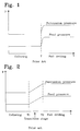
- Figure 1 shows a timing diagram of a prior art method for collaring.
- Figure 2 shows a timing diagram of another prior art method for collaring.
- Figure 3 shows a timing diagram of a method for collaring in accordance with the invention.
- Figure 4 schematically shows a system in which the present invention may be utilised.
- The prior art method for performing collaring described above is shown in figure 1. During collaring, this method starts with a reduced feed force and percussion force. No parameter control is thus performed, the pressure increase is due to valves and ducts used in the hydraulic system.
- In figure 2, the second of the above disclosed, previously known methods for controlling electric and computer controlled hydraulic systems is shown, in which a suitable transition occurs between the initial stage, and its corresponding values, and the final stage, in which the drilling machine is run at full capacity.
- This method comprises a number of parameters that has to be set. Initial values have to be determined, and, also, for how long this stage with reduced power is to go on. Further, the aspects of the transition stage illustrated in figure 2, between the points T1 and T2, have to be determined. In other words, it has to be determined what the transition step should look like in order for it to be smooth enough. At the same time it is undesired to drill with the reduced power too long, since time then is lost.
- With the above described solution, in some situations, there is a risk of hysteresis in the valves of the system, i.e., self-oscillation in the system. This may occur, for example, when drilling in soft and/or fissured rock, when the drill steel shank suddenly is not in percussion position anymore, and it is necessary to go down to the collaring level values of the percussion pressure. Then, it has to be started over from the beginning with a new collaring stage followed by a transition stage, before the system again is run at full capacity. This can be repeated several times, thus resulting in a very time consuming mode of operation.
- According to the present invention, all the above drawbacks are avoided. With reference to figure 3, a method for collaring according to the present invention will now be described.
- In collaring according to the present invention, start values for the percussion pressure of the drilling machine (and thereby the percussion power of the drilling machine), and the feed pressure are chosen. These values are chosen such that the collaring is smooth enough to ensure that the hole obtains correct direction and position, while at the same time the pressure cannot be so low that it may cause problems in the drilling machine. For example, start values are advantageously chosen to be slightly higher than the accumulator pressure in order to avoid problems with included membranes. The start values should, off course, neither be too low to accomplish a collaring hole. The start values may, for example, in an ordinary drilling machine, be about 130 bar.
- The initial phase, or collaring phase, is then controlled by continuously increasing functions. In the preferred embodiment, the continuously increasing functions have a gradually increasing derivative, as is shown in figure 3, which results in the preferred, smooth transition. One example of a function, which advantageously may be used, is the mathematically well known exponential function, but any substantially continuous function in accordance with the mentioned requirements may be used.
- The use of a continuous function of time with a gradually increasing derivative results in a system with only two control stages, of which the parameters of the first stage, the collaring, includes the start values of the percussion pressure, the feed pressure and the length of the initial stage. Thereby, the number of parameters needed to be set is minimised. During the collaring stage, the percussion pressure and feed pressure are controlled independently, but with the same duration, i.e. throughout the collaring stage.
- The feed pressure should, however, be supervised by means of the system RPCF function (Rotation Pressure Controlled Feed) during the collaring stage. The RPCF function controls the feed pressure such that the rotation pressure and/or torque is substantially constant in order to ensure that the drill string component joints are suitably tightened. This function is of particular importance during full drilling, when the power is higher.
- In order to limit the percussion pressure of the drilling machine when the drill steel shank is out of position for percussion, the damping pressure of the drilling machine should be supervised so that the percussion pressure is limited to, for example, the start values if the damping pressure with certainty does not exceed the no-load pressure of the damper. As is well known to a person skilled in the art, the damper is used to damp the reflexions which arise when the drill steel hits the rock. As also is well known to a person skilled in the art, the damping pressure may be used to ensure that the drill steel is in contact with the rock at time of percussion. The initial stage may, in other words, be combined with the supervision of the damping pressure so that the percussion pressure does not run away from the feed pressure.
- However, it is not always necessary to go down to the start values, even if this usually is the case since these have been chosen with regard to, among other things, the accumulator pressure. By utilising the present invention, using the control by means of continuous functions, the risk for self-oscillation is avoided in the system. Accordingly, it is not always necessary to go down to the lowest level in the collaring, i.e. the start values, if soft rock is encountered, but it is possible to go down to a level where the percussion pressure is limited with regard to the no-load pressure of the damper. Alternatively, the percussion pressure may be lowered when the feed pressure is or goes below a predetermined level.
- An operator may chose between the setting of a desired hole depth of the collaring, or for how long the initial phase should go on.
- Finally, the stop values may also be determined, which advantageously correspond to the full power of the drilling machine. It may, however, in some situations, be necessary to run the machine at a reduced power, whereby desired values may be set.
- Figure 4 schematically shows a system 1, in which the present invention may be utilised. The system 1 includes, in its simplest embodiment, a
drilling machine 2 with acontrol system 3, by means of which an operator may control the system 1. The control system may be integrated with thedrilling machine 2, or be separately connected. - In summary, by means of the present invention, a continuous, smooth collaring is achieved, in which the parameters that has to be set by an operator can be minimised, and in which several different stages with accompanying parameter settings are avoided altogether.
Claims (10)
- Method for controlling drilling parameters during an initial phase of drilling in rock with a drilling machine, characterised in that the percussion pressure and feed pressure of the drilling machine are controlled as continuously increasing functions of time during said initial phase.
- Method as claimed in claim 1, wherein said controlling is represented by continuous functions of time with a gradually increasing derivative.
- Method as claimed in claim 1 or 2, wherein said continuous functions consist of exponential functions.
- Method as claimed in any of claims 1-3, wherein the feed pressure is controlled on the basis of the rotation pressure.
- Method as claimed in claim 4, wherein the percussion pressure is lowered when the feed pressure is or goes below a predetermined level.
- System for controlling drilling parameters during an initial phase of drilling in rock with a drilling machine, characterised in that the system includes means for controlling the percussion pressure and feed pressure of the drilling machine as continuously increasing functions of time during said initial phase.
- System as claimed in claim 6, wherein said controlling is represented by continuous functions of time with gradually increasing derivative.
- System according to claim 6 or 7, wherein said continuous functions consist of exponential functions.
- System according to any of the claims 6-8, wherein the system includes means for controlling the feed pressure on the basis of the rotation pressure.
- System according to claim 9, wherein the system includes means for lowering the percussion pressure when the feed pressure is or goes below a predetermined level.
Applications Claiming Priority (2)
| Application Number | Priority Date | Filing Date | Title |
|---|---|---|---|
| SE0401472A SE528699C2 (en) | 2004-06-09 | 2004-06-09 | Method and system for controlling drilling parameters under carving |
| PCT/SE2005/000819 WO2005121506A1 (en) | 2004-06-09 | 2005-05-31 | Method and system for collaring |
Publications (2)
| Publication Number | Publication Date |
|---|---|
| EP1766186A1 EP1766186A1 (en) | 2007-03-28 |
| EP1766186B1 true EP1766186B1 (en) | 2007-11-14 |
Family
ID=32653565
Family Applications (1)
| Application Number | Title | Priority Date | Filing Date |
|---|---|---|---|
| EP05746886A Expired - Lifetime EP1766186B1 (en) | 2004-06-09 | 2005-05-31 | Method and system for collaring |
Country Status (12)
| Country | Link |
|---|---|
| US (1) | US7762346B2 (en) |
| EP (1) | EP1766186B1 (en) |
| JP (1) | JP4759566B2 (en) |
| CN (1) | CN1950586B (en) |
| AT (1) | ATE378502T1 (en) |
| AU (1) | AU2005252606B2 (en) |
| CA (1) | CA2561894C (en) |
| DE (1) | DE602005003371T2 (en) |
| ES (1) | ES2293580T3 (en) |
| SE (1) | SE528699C2 (en) |
| WO (1) | WO2005121506A1 (en) |
| ZA (1) | ZA200608971B (en) |
Cited By (1)
| Publication number | Priority date | Publication date | Assignee | Title |
|---|---|---|---|---|
| EP2140106A4 (en) * | 2007-04-11 | 2015-11-18 | Atlas Copco Rock Drills Ab | METHOD AND DEVICE FOR ADJUSTING AT LEAST ONE DRILLING PARAMETER FOR DRILLING ROCKS |
Families Citing this family (6)
| Publication number | Priority date | Publication date | Assignee | Title |
|---|---|---|---|---|
| SE532482C2 (en) * | 2007-04-11 | 2010-02-02 | Atlas Copco Rock Drills Ab | Method, apparatus and rock drilling rig for controlling at least one drilling parameter |
| SE533986C2 (en) * | 2008-10-10 | 2011-03-22 | Atlas Copco Rock Drills Ab | Method device and drilling rig and computerized control system for controlling a rock drill when drilling in rock |
| US8261855B2 (en) | 2009-11-11 | 2012-09-11 | Flanders Electric, Ltd. | Methods and systems for drilling boreholes |
| CN103556943B (en) * | 2013-11-08 | 2016-05-11 | 阿特拉斯科普柯(南京)建筑矿山设备有限公司 | According to the method for the ballistic work of feeding force control rock drilling system and device |
| US11401795B2 (en) | 2019-07-19 | 2022-08-02 | Caterpillar Global Mining Equipment Llc | Collar control system for mobile drilling machines |
| WO2026030633A1 (en) * | 2024-08-01 | 2026-02-05 | Flanders Electric Motor Service, Llc | Adaptive auto-drilling for drilling applications |
Family Cites Families (11)
| Publication number | Priority date | Publication date | Assignee | Title |
|---|---|---|---|---|
| US3670826A (en) * | 1970-09-11 | 1972-06-20 | Gardner Denver Co | Control system for drills |
| SE444528B (en) * | 1983-01-26 | 1986-04-21 | Stabilator Ab | SET AND DEVICE TO CONTROL SHOCK ENERGY WITH A SHOCK DRILL AS A FUNCTION OF THE DRILL NECK'S LEG |
| FI90276C (en) | 1991-01-03 | 1994-01-10 | Tamrock Oy | Procedure for drilling a hole in rock |
| FI95166C (en) * | 1994-04-14 | 1995-12-27 | Tamrock Oy | Arrangement in a pressure-driven rock drilling rig |
| FI104279B1 (en) | 1996-11-27 | 1999-12-15 | Tamrock Oy | Procedure for controlling the feed during rock drilling |
| FI981707A0 (en) | 1998-08-06 | 1998-08-06 | Tamrock Oy | An arrangement for controlling rock drilling |
| JP2000119715A (en) * | 1998-10-06 | 2000-04-25 | Yamamoto Lock Machine Kk | Hydraulic drilling machine |
| JP2001254702A (en) * | 2000-03-08 | 2001-09-21 | Kobelco Contstruction Machinery Ltd | Hydraulic actuator control method of working machine and hydraulic actuator control device |
| JP2002266008A (en) * | 2001-03-09 | 2002-09-18 | Mazda Earth Technologies Co Ltd | Hydraulic tap hole opening machine |
| FI118306B (en) * | 2001-12-07 | 2007-09-28 | Sandvik Tamrock Oy | Methods and devices for controlling the operation of a rock drilling device |
| FI121218B (en) * | 2003-07-07 | 2010-08-31 | Sandvik Mining & Constr Oy | A method for providing a tension pulse to a tool and a pressurized fluid impactor |
-
2004
- 2004-06-09 SE SE0401472A patent/SE528699C2/en not_active IP Right Cessation
-
2005
- 2005-05-31 AT AT05746886T patent/ATE378502T1/en active
- 2005-05-31 ES ES05746886T patent/ES2293580T3/en not_active Expired - Lifetime
- 2005-05-31 CA CA2561894A patent/CA2561894C/en not_active Expired - Lifetime
- 2005-05-31 EP EP05746886A patent/EP1766186B1/en not_active Expired - Lifetime
- 2005-05-31 DE DE602005003371T patent/DE602005003371T2/en not_active Expired - Lifetime
- 2005-05-31 WO PCT/SE2005/000819 patent/WO2005121506A1/en not_active Ceased
- 2005-05-31 ZA ZA200608971A patent/ZA200608971B/en unknown
- 2005-05-31 AU AU2005252606A patent/AU2005252606B2/en not_active Expired
- 2005-05-31 CN CN2005800137130A patent/CN1950586B/en not_active Expired - Lifetime
- 2005-05-31 JP JP2007527130A patent/JP4759566B2/en not_active Expired - Lifetime
- 2005-05-31 US US11/578,868 patent/US7762346B2/en active Active
Cited By (1)
| Publication number | Priority date | Publication date | Assignee | Title |
|---|---|---|---|---|
| EP2140106A4 (en) * | 2007-04-11 | 2015-11-18 | Atlas Copco Rock Drills Ab | METHOD AND DEVICE FOR ADJUSTING AT LEAST ONE DRILLING PARAMETER FOR DRILLING ROCKS |
Also Published As
| Publication number | Publication date |
|---|---|
| US20070209812A1 (en) | 2007-09-13 |
| WO2005121506A1 (en) | 2005-12-22 |
| CN1950586B (en) | 2010-11-03 |
| JP2008502834A (en) | 2008-01-31 |
| SE528699C2 (en) | 2007-01-30 |
| ES2293580T3 (en) | 2008-03-16 |
| WO2005121506A9 (en) | 2007-01-11 |
| CA2561894C (en) | 2013-01-08 |
| ATE378502T1 (en) | 2007-11-15 |
| SE0401472D0 (en) | 2004-06-09 |
| CN1950586A (en) | 2007-04-18 |
| SE0401472L (en) | 2005-12-10 |
| EP1766186A1 (en) | 2007-03-28 |
| WO2005121506A8 (en) | 2007-04-05 |
| DE602005003371T2 (en) | 2008-03-13 |
| CA2561894A1 (en) | 2005-12-22 |
| AU2005252606A1 (en) | 2005-12-22 |
| JP4759566B2 (en) | 2011-08-31 |
| ZA200608971B (en) | 2008-06-25 |
| DE602005003371D1 (en) | 2007-12-27 |
| US7762346B2 (en) | 2010-07-27 |
| AU2005252606B2 (en) | 2010-07-01 |
Similar Documents
| Publication | Publication Date | Title |
|---|---|---|
| RU2426872C1 (en) | Automatic drilling practice with constant parameter of control of pressure derivative | |
| US7721821B2 (en) | Underground boring machine and method for controlling underground boring | |
| WO2018106287A1 (en) | System and method for controlling a drilling machine | |
| CA2143596A1 (en) | Apparatus and method for drilling boreholes | |
| US20050056439A1 (en) | Method and equipment for controlling operation of rock drilling apparatus | |
| SE0303548D0 (en) | A rock drilling method | |
| US7762346B2 (en) | Method and system for collaring | |
| JP3218331B2 (en) | Rock drilling method | |
| KR20190075903A (en) | Method and construction apparatus for soil processing | |
| AU727129B2 (en) | Method of and apparatus for controlling diamond drill feed | |
| CA2581324C (en) | Arrangement for controlling percussive rock drilling | |
| CN101512102A (en) | Method for drilling rock | |
| CN118997681A (en) | Self-adaptive coring drilling control system and method of coring drilling machine and coring drilling machine | |
| CN115469536B (en) | A method for assessing the risk of stuck drill and adjusting drilling parameters | |
| US20240033831A1 (en) | Method for improved starting of drilling with a drilling device in an existing borehole, and drilling system | |
| RU2026973C1 (en) | System for control of diamond drilling practices | |
| SU1714068A1 (en) | Turbodrilling method | |
| SU1578323A2 (en) | Automatic control system for core drilling | |
| JP2003055967A (en) | Penetration method of steel pipe pile |
Legal Events
| Date | Code | Title | Description |
|---|---|---|---|
| PUAI | Public reference made under article 153(3) epc to a published international application that has entered the european phase |
Free format text: ORIGINAL CODE: 0009012 |
|
| 17P | Request for examination filed |
Effective date: 20061211 |
|
| AK | Designated contracting states |
Kind code of ref document: A1 Designated state(s): AT BE BG CH CY CZ DE DK EE ES FI FR GB GR HU IE IS IT LI LT LU MC NL PL PT RO SE SI SK TR |
|
| GRAP | Despatch of communication of intention to grant a patent |
Free format text: ORIGINAL CODE: EPIDOSNIGR1 |
|
| DAX | Request for extension of the european patent (deleted) | ||
| GRAS | Grant fee paid |
Free format text: ORIGINAL CODE: EPIDOSNIGR3 |
|
| GRAA | (expected) grant |
Free format text: ORIGINAL CODE: 0009210 |
|
| AK | Designated contracting states |
Kind code of ref document: B1 Designated state(s): AT BE BG CH CY CZ DE DK EE ES FI FR GB GR HU IE IS IT LI LT LU MC NL PL PT RO SE SI SK TR |
|
| REG | Reference to a national code |
Ref country code: GB Ref legal event code: FG4D |
|
| REG | Reference to a national code |
Ref country code: CH Ref legal event code: EP Ref country code: CH Ref legal event code: NV Representative=s name: E. BLUM & CO. AG PATENT- UND MARKENANWAELTE VSP |
|
| REG | Reference to a national code |
Ref country code: IE Ref legal event code: FG4D |
|
| REF | Corresponds to: |
Ref document number: 602005003371 Country of ref document: DE Date of ref document: 20071227 Kind code of ref document: P |
|
| REG | Reference to a national code |
Ref country code: ES Ref legal event code: FG2A Ref document number: 2293580 Country of ref document: ES Kind code of ref document: T3 |
|
| PG25 | Lapsed in a contracting state [announced via postgrant information from national office to epo] |
Ref country code: SE Free format text: LAPSE BECAUSE OF FAILURE TO SUBMIT A TRANSLATION OF THE DESCRIPTION OR TO PAY THE FEE WITHIN THE PRESCRIBED TIME-LIMIT Effective date: 20080214 Ref country code: NL Free format text: LAPSE BECAUSE OF FAILURE TO SUBMIT A TRANSLATION OF THE DESCRIPTION OR TO PAY THE FEE WITHIN THE PRESCRIBED TIME-LIMIT Effective date: 20071114 |
|
| NLV1 | Nl: lapsed or annulled due to failure to fulfill the requirements of art. 29p and 29m of the patents act | ||
| PG25 | Lapsed in a contracting state [announced via postgrant information from national office to epo] |
Ref country code: PL Free format text: LAPSE BECAUSE OF FAILURE TO SUBMIT A TRANSLATION OF THE DESCRIPTION OR TO PAY THE FEE WITHIN THE PRESCRIBED TIME-LIMIT Effective date: 20071114 Ref country code: IS Free format text: LAPSE BECAUSE OF FAILURE TO SUBMIT A TRANSLATION OF THE DESCRIPTION OR TO PAY THE FEE WITHIN THE PRESCRIBED TIME-LIMIT Effective date: 20080314 Ref country code: BG Free format text: LAPSE BECAUSE OF FAILURE TO SUBMIT A TRANSLATION OF THE DESCRIPTION OR TO PAY THE FEE WITHIN THE PRESCRIBED TIME-LIMIT Effective date: 20080214 Ref country code: LT Free format text: LAPSE BECAUSE OF FAILURE TO SUBMIT A TRANSLATION OF THE DESCRIPTION OR TO PAY THE FEE WITHIN THE PRESCRIBED TIME-LIMIT Effective date: 20071114 Ref country code: SI Free format text: LAPSE BECAUSE OF FAILURE TO SUBMIT A TRANSLATION OF THE DESCRIPTION OR TO PAY THE FEE WITHIN THE PRESCRIBED TIME-LIMIT Effective date: 20071114 |
|
| ET | Fr: translation filed | ||
| PG25 | Lapsed in a contracting state [announced via postgrant information from national office to epo] |
Ref country code: DK Free format text: LAPSE BECAUSE OF FAILURE TO SUBMIT A TRANSLATION OF THE DESCRIPTION OR TO PAY THE FEE WITHIN THE PRESCRIBED TIME-LIMIT Effective date: 20071114 Ref country code: CZ Free format text: LAPSE BECAUSE OF FAILURE TO SUBMIT A TRANSLATION OF THE DESCRIPTION OR TO PAY THE FEE WITHIN THE PRESCRIBED TIME-LIMIT Effective date: 20071114 |
|
| PG25 | Lapsed in a contracting state [announced via postgrant information from national office to epo] |
Ref country code: SK Free format text: LAPSE BECAUSE OF FAILURE TO SUBMIT A TRANSLATION OF THE DESCRIPTION OR TO PAY THE FEE WITHIN THE PRESCRIBED TIME-LIMIT Effective date: 20071114 Ref country code: RO Free format text: LAPSE BECAUSE OF FAILURE TO SUBMIT A TRANSLATION OF THE DESCRIPTION OR TO PAY THE FEE WITHIN THE PRESCRIBED TIME-LIMIT Effective date: 20071114 Ref country code: BE Free format text: LAPSE BECAUSE OF FAILURE TO SUBMIT A TRANSLATION OF THE DESCRIPTION OR TO PAY THE FEE WITHIN THE PRESCRIBED TIME-LIMIT Effective date: 20071114 |
|
| PLBE | No opposition filed within time limit |
Free format text: ORIGINAL CODE: 0009261 |
|
| STAA | Information on the status of an ep patent application or granted ep patent |
Free format text: STATUS: NO OPPOSITION FILED WITHIN TIME LIMIT |
|
| PG25 | Lapsed in a contracting state [announced via postgrant information from national office to epo] |
Ref country code: PT Free format text: LAPSE BECAUSE OF FAILURE TO SUBMIT A TRANSLATION OF THE DESCRIPTION OR TO PAY THE FEE WITHIN THE PRESCRIBED TIME-LIMIT Effective date: 20080414 |
|
| 26N | No opposition filed |
Effective date: 20080815 |
|
| PG25 | Lapsed in a contracting state [announced via postgrant information from national office to epo] |
Ref country code: MC Free format text: LAPSE BECAUSE OF NON-PAYMENT OF DUE FEES Effective date: 20080531 |
|
| PG25 | Lapsed in a contracting state [announced via postgrant information from national office to epo] |
Ref country code: GR Free format text: LAPSE BECAUSE OF FAILURE TO SUBMIT A TRANSLATION OF THE DESCRIPTION OR TO PAY THE FEE WITHIN THE PRESCRIBED TIME-LIMIT Effective date: 20080215 |
|
| PG25 | Lapsed in a contracting state [announced via postgrant information from national office to epo] |
Ref country code: EE Free format text: LAPSE BECAUSE OF FAILURE TO SUBMIT A TRANSLATION OF THE DESCRIPTION OR TO PAY THE FEE WITHIN THE PRESCRIBED TIME-LIMIT Effective date: 20071114 |
|
| PG25 | Lapsed in a contracting state [announced via postgrant information from national office to epo] |
Ref country code: CY Free format text: LAPSE BECAUSE OF FAILURE TO SUBMIT A TRANSLATION OF THE DESCRIPTION OR TO PAY THE FEE WITHIN THE PRESCRIBED TIME-LIMIT Effective date: 20071114 |
|
| PG25 | Lapsed in a contracting state [announced via postgrant information from national office to epo] |
Ref country code: LU Free format text: LAPSE BECAUSE OF NON-PAYMENT OF DUE FEES Effective date: 20080531 Ref country code: HU Free format text: LAPSE BECAUSE OF FAILURE TO SUBMIT A TRANSLATION OF THE DESCRIPTION OR TO PAY THE FEE WITHIN THE PRESCRIBED TIME-LIMIT Effective date: 20080515 |
|
| PG25 | Lapsed in a contracting state [announced via postgrant information from national office to epo] |
Ref country code: TR Free format text: LAPSE BECAUSE OF FAILURE TO SUBMIT A TRANSLATION OF THE DESCRIPTION OR TO PAY THE FEE WITHIN THE PRESCRIBED TIME-LIMIT Effective date: 20071114 |
|
| REG | Reference to a national code |
Ref country code: DE Ref legal event code: R082 Ref document number: 602005003371 Country of ref document: DE Representative=s name: PATENTANWAELTE OLBRICHT, BUCHHOLD, KEULERTZ PA, DE |
|
| REG | Reference to a national code |
Ref country code: FR Ref legal event code: PLFP Year of fee payment: 12 |
|
| REG | Reference to a national code |
Ref country code: FR Ref legal event code: PLFP Year of fee payment: 13 |
|
| REG | Reference to a national code |
Ref country code: ES Ref legal event code: PC2A Owner name: EPIROC ROCK DRILLS AKTIEBOLAG Effective date: 20180319 |
|
| REG | Reference to a national code |
Ref country code: CH Ref legal event code: PFA Owner name: EPIROC ROCK DRILLS AKTIEBOLAG, SE Free format text: FORMER OWNER: ATLAS COPCO ROCK DRILLS AB, SE |
|
| REG | Reference to a national code |
Ref country code: AT Ref legal event code: HC Ref document number: 378502 Country of ref document: AT Kind code of ref document: T Owner name: EPIROC ROCK DRILLS AKTIEBOLAG, SE Effective date: 20180326 |
|
| REG | Reference to a national code |
Ref country code: FR Ref legal event code: PLFP Year of fee payment: 14 |
|
| REG | Reference to a national code |
Ref country code: DE Ref legal event code: R082 Ref document number: 602005003371 Country of ref document: DE Representative=s name: PATENTANWAELTE OLBRICHT, BUCHHOLD, KEULERTZ PA, DE Ref country code: DE Ref legal event code: R081 Ref document number: 602005003371 Country of ref document: DE Owner name: EPIROC ROCK DRILLS AKTIEBOLAG, SE Free format text: FORMER OWNER: ATLAS COPCO ROCK DRILLS AB, OEREBRO, SE |
|
| REG | Reference to a national code |
Ref country code: FR Ref legal event code: CD Owner name: EPIROC ROCK DRILLS AKTIEBOLAG, SE Effective date: 20181107 |
|
| PGFP | Annual fee paid to national office [announced via postgrant information from national office to epo] |
Ref country code: CY Payment date: 20190502 Year of fee payment: 15 Ref country code: ES Payment date: 20190603 Year of fee payment: 15 Ref country code: IE Payment date: 20190528 Year of fee payment: 15 Ref country code: DE Payment date: 20190530 Year of fee payment: 15 |
|
| PGFP | Annual fee paid to national office [announced via postgrant information from national office to epo] |
Ref country code: CH Payment date: 20190604 Year of fee payment: 15 |
|
| PGFP | Annual fee paid to national office [announced via postgrant information from national office to epo] |
Ref country code: AT Payment date: 20190503 Year of fee payment: 15 Ref country code: GB Payment date: 20190528 Year of fee payment: 15 |
|
| REG | Reference to a national code |
Ref country code: DE Ref legal event code: R119 Ref document number: 602005003371 Country of ref document: DE |
|
| REG | Reference to a national code |
Ref country code: AT Ref legal event code: MM01 Ref document number: 378502 Country of ref document: AT Kind code of ref document: T Effective date: 20200531 |
|
| PG25 | Lapsed in a contracting state [announced via postgrant information from national office to epo] |
Ref country code: AT Free format text: LAPSE BECAUSE OF NON-PAYMENT OF DUE FEES Effective date: 20200531 Ref country code: LI Free format text: LAPSE BECAUSE OF NON-PAYMENT OF DUE FEES Effective date: 20200531 Ref country code: CH Free format text: LAPSE BECAUSE OF NON-PAYMENT OF DUE FEES Effective date: 20200531 |
|
| GBPC | Gb: european patent ceased through non-payment of renewal fee |
Effective date: 20200531 |
|
| PG25 | Lapsed in a contracting state [announced via postgrant information from national office to epo] |
Ref country code: IE Free format text: LAPSE BECAUSE OF NON-PAYMENT OF DUE FEES Effective date: 20200531 Ref country code: GB Free format text: LAPSE BECAUSE OF NON-PAYMENT OF DUE FEES Effective date: 20200531 |
|
| PG25 | Lapsed in a contracting state [announced via postgrant information from national office to epo] |
Ref country code: DE Free format text: LAPSE BECAUSE OF NON-PAYMENT OF DUE FEES Effective date: 20201201 |
|
| REG | Reference to a national code |
Ref country code: ES Ref legal event code: FD2A Effective date: 20211006 |
|
| PG25 | Lapsed in a contracting state [announced via postgrant information from national office to epo] |
Ref country code: IT Free format text: LAPSE BECAUSE OF NON-PAYMENT OF DUE FEES Effective date: 20200531 |
|
| PG25 | Lapsed in a contracting state [announced via postgrant information from national office to epo] |
Ref country code: ES Free format text: LAPSE BECAUSE OF NON-PAYMENT OF DUE FEES Effective date: 20200601 |
|
| PGFP | Annual fee paid to national office [announced via postgrant information from national office to epo] |
Ref country code: FR Payment date: 20220525 Year of fee payment: 18 |
|
| PG25 | Lapsed in a contracting state [announced via postgrant information from national office to epo] |
Ref country code: FR Free format text: LAPSE BECAUSE OF NON-PAYMENT OF DUE FEES Effective date: 20230531 |
|
| PGFP | Annual fee paid to national office [announced via postgrant information from national office to epo] |
Ref country code: FI Payment date: 20240418 Year of fee payment: 20 |