EP1764791A1 - Method and device for reading angular multiplexed pits - Google Patents
Method and device for reading angular multiplexed pits Download PDFInfo
- Publication number
- EP1764791A1 EP1764791A1 EP05108557A EP05108557A EP1764791A1 EP 1764791 A1 EP1764791 A1 EP 1764791A1 EP 05108557 A EP05108557 A EP 05108557A EP 05108557 A EP05108557 A EP 05108557A EP 1764791 A1 EP1764791 A1 EP 1764791A1
- Authority
- EP
- European Patent Office
- Prior art keywords
- detector
- pit
- angular
- optical recording
- signals
- Prior art date
- Legal status (The legal status is an assumption and is not a legal conclusion. Google has not performed a legal analysis and makes no representation as to the accuracy of the status listed.)
- Withdrawn
Links
- 238000000034 method Methods 0.000 title claims abstract description 19
- 230000003287 optical effect Effects 0.000 claims abstract description 26
- 230000001678 irradiating effect Effects 0.000 claims abstract description 5
- 238000011896 sensitive detection Methods 0.000 claims description 5
- 230000010363 phase shift Effects 0.000 description 4
- 230000010287 polarization Effects 0.000 description 4
- 238000001514 detection method Methods 0.000 description 3
- 238000004088 simulation Methods 0.000 description 3
- 230000000694 effects Effects 0.000 description 2
- 230000035945 sensitivity Effects 0.000 description 2
- 238000012935 Averaging Methods 0.000 description 1
- 201000009310 astigmatism Diseases 0.000 description 1
- 238000012986 modification Methods 0.000 description 1
- 230000004048 modification Effects 0.000 description 1
- 230000000737 periodic effect Effects 0.000 description 1
Images


Classifications
-
- G—PHYSICS
- G11—INFORMATION STORAGE
- G11B—INFORMATION STORAGE BASED ON RELATIVE MOVEMENT BETWEEN RECORD CARRIER AND TRANSDUCER
- G11B7/00—Recording or reproducing by optical means, e.g. recording using a thermal beam of optical radiation by modifying optical properties or the physical structure, reproducing using an optical beam at lower power by sensing optical properties; Record carriers therefor
- G11B7/12—Heads, e.g. forming of the optical beam spot or modulation of the optical beam
- G11B7/13—Optical detectors therefor
Definitions
- the present invention relates to a method and a device for reading angular multiplexed pits from optical recording media, and to an apparatus for reading from optical recording media using such method or device.
- a well-known method to increase the storage capacity of optical recording media is to use a pit-substructure, e.g. the angular position of periodically aligned pits.
- This technology allows the storage of several bits of information in a single pit.
- Different pit shapes have been proposed to generate detectable angular signals, e.g. pits with one or more steps in depth, rotated "long pits", rotated “double-pits”, etc.
- detectable angular signals e.g. pits with one or more steps in depth, rotated "long pits”, rotated “double-pits”, etc.
- pits having an angular substructure in the form of a step being placed at one of 332 different angles is described.
- Illuminating non-rotational symmetric, reflective pit structures on a disk with a focused laser beam results in a non-rotational symmetric image on the detector.
- a special detector structure it is possible to detect the angular substructure of the pits on the recording medium and to retrieve the stored information.
- US 5,617,389 discloses a detector for determining the rotation angle of angular multiplexed pits.
- the detector consists of a photodetector which is divided into eight light receiving areas. These areas approximately form a circular cylinder shape as a whole.
- a computing circuit calculates a plurality of information and error signals from the output signals of the light receiving areas.
- this object is achieved by a method for detecting a rotation angle of an angular rotated pit on an optical recording medium, having the steps of:
- this object is also achieved by a device for detecting a rotation angle of an angular rotated pit on an optical recording medium, including:
- the border between the detector areas is essentially parallel to a track on the optical recording medium.
- the detector areas yields at least two different signals. The peaks (or the phase) of these signals are shifted relative to each other. The shift depends on the rotation angle of the pit.
- the detector is a four quadrant detector. This has the advantage that a conventional pickup with a quadrant detector can be used to detect the rotation angle of a rotated pit. Therefore, no hardware modification is necessary.
- tracking can be realized using the well known push-pull, focus error control with knife edge or astigmatism methods.
- a pickup employing a method or a device according to the invention can be used both with conventional and angular multiplexed optical recording media.
- tracking errors also lead to a phase shift of the signals of the different detector areas, this phase shift is rather small compared to the phase shift caused by the rotated pits.
- this phase shift has a low frequency and can easily be separated from the highfrequency signals of the rotated pits.
- the at least two detector signals and the difference signal are determined in dependence of the position of the angular rotated pit in track direction relative to the mark center.
- a phase sensitive detection of the signals can be realized when the pits are arranged periodically on the optical recording medium, e.g. by determining the difference signal at two different positions of the angular rotated pit relative to the mark center.
- the phase sensitive detection increases the sensitivity of the rotation angle determination.
- a sum signal of the at least two detector signals is also generated. This extends the range of detectable rotation angles to -90° to 90°, which is limited to -45° to 45° if only the difference signal is used.
- an apparatus for reading from optical recording media includes a device according to the invention or means for performing a method according to the invention for detecting a rotation angle of an angular rotated pit on an optical recording medium.
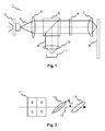
- a pickup 1 for reading angular multiplexed pits is shown schematically.
- a laser diode 2 emits a linearly polarized light beam 3, which is collimated by a collimator lens 4.
- the collimated light beam 3 passes a polarization beam splitter 5 and a quarter wave plate 6, which transforms the light beam 3 into a circular polarized light beam 3, before it is focused onto an optical recording medium 8 by an objective lens 7.
- the light beam 9 reflected by the optical recording medium is collimated by the objective lens 7 and passes the quarter wave plate 6, which transforms the reflected light beam 9 into a linear polarized light beam 9.
- the direction of polarization of the reflected light beam 9 is perpendicular to the direction of polarization of the initial light beam 3.
- the reflected light beam 9 is consequently deflected by the polarization beam splitter 5 towards a focusing lens 10, which focuses the reflected light beam 9 onto a detector 11.
- the detector 11 has at least two detector areas.
- the detector 11 is a four quadrant detector.
- the position of the detector quadrants of the pickup 1 relative to a track 12 of the optical recording medium 8 and the angular rotated pits 13, 14 is depicted in Fig. 2.
- the first pit 13 is rotated relative to the track 12 by a rotation angle of u.
- the signal combination PS (x) A (x) +B (x) -C (x) -D (x) is used, where x denotes the position of the pit.
- x denotes the position of the pit.
- the result is shown in Fig. 5 for four different rotation angles.
- the dashed rectangles indicate areas with a large sensitivity.
- the signals for the rotation angles of -45° and 45° can easily be discriminated from the signal for a rotation angle of 0°.
- the signals for rotation angles between -45° and 45° lie between the depicted signals.
- angular rotated pits are aligned periodically on the optical recording medium. Therefore, it is relatively simple to derive a clock signal which yields information about the actual position of each pit relative to the mark center. If the pits are not aligned periodically, the signals generated by a pit need to be stored and subsequently evaluated.
- PS(x) phase sensitive detection
- the derived signal is comparable to the known DPD (differential phase detection) or DTD (differential time detection) tracking signal for DVD systems.
- DPD differential phase detection
- DTD differential time detection
- the phase shifting effect is very small so that averaging about a lot of pits is necessary.
- the length of the rotated edge is much larger. The effect is, therefore, significantly stronger.
- the periodic arrangement of the pits allows a phase sensitive detection of the rotation angle u, which improves the signal to noise ratio.
Landscapes
- Physics & Mathematics (AREA)
- Optics & Photonics (AREA)
- Optical Recording Or Reproduction (AREA)
- Optical Record Carriers And Manufacture Thereof (AREA)
Abstract
The present invention relates to a method and a device 1 for reading angular multiplexed pits 13, 14 from optical recording media 8, and to an apparatus for reading from optical recording media using such method or device.
According to the invention, a method for detecting a rotation angle of an angular rotated pit (13, 14) on an optical recording medium (8) includes the steps of:
- irradiating the angular rotated pit (13, 14) with a light beam (9);
- determining at least two detector signals (A+B, C+D) for a light beam (9) reflected by the angular rotated pit (13, 14) with at least two detector areas of a detector (11); and
- calculating a difference signal (PS) of the at least two detector signals (A+B, C+D).
According to the invention, a method for detecting a rotation angle of an angular rotated pit (13, 14) on an optical recording medium (8) includes the steps of:
- irradiating the angular rotated pit (13, 14) with a light beam (9);
- determining at least two detector signals (A+B, C+D) for a light beam (9) reflected by the angular rotated pit (13, 14) with at least two detector areas of a detector (11); and
- calculating a difference signal (PS) of the at least two detector signals (A+B, C+D).
Description
- The present invention relates to a method and a device for reading angular multiplexed pits from optical recording media, and to an apparatus for reading from optical recording media using such method or device.
- A well-known method to increase the storage capacity of optical recording media is to use a pit-substructure, e.g. the angular position of periodically aligned pits. This technology allows the storage of several bits of information in a single pit. Different pit shapes have been proposed to generate detectable angular signals, e.g. pits with one or more steps in depth, rotated "long pits", rotated "double-pits", etc. For example, in "DVD disks shine from all angles, Physics World November 2004", pits having an angular substructure in the form of a step being placed at one of 332 different angles is described. Illuminating non-rotational symmetric, reflective pit structures on a disk with a focused laser beam results in a non-rotational symmetric image on the detector. By using a special detector structure, it is possible to detect the angular substructure of the pits on the recording medium and to retrieve the stored information.
- For example,
US 5,617,389 discloses a detector for determining the rotation angle of angular multiplexed pits. The detector consists of a photodetector which is divided into eight light receiving areas. These areas approximately form a circular cylinder shape as a whole. A computing circuit calculates a plurality of information and error signals from the output signals of the light receiving areas. - It is an object of the invention to propose a method and a device for efficiently reading angular multiplexed pits from optical recording media using a simplified detector structure.
- According to a first aspect of the invention, this object is achieved by a method for detecting a rotation angle of an angular rotated pit on an optical recording medium, having the steps of:
- irradiating the angular rotated pit with a light beam;
- determining at least two detector signals for a light beam reflected by the angular rotated pit with at least two detector areas of a detector; and
- calculating a difference signal of the at least two detector signals.
- According to a second aspect of the invention, this object is also achieved by a device for detecting a rotation angle of an angular rotated pit on an optical recording medium, including:
- a light source for irradiating the angular rotated pit with a light beam;
- a detector having at least two detector areas for determining at least two detector signals for a light beam reflected by the angular rotated pit; and
- a calculating unit for calculating a difference signal of the at least two detector signals.
- Advantageously, the border between the detector areas is essentially parallel to a track on the optical recording medium. When an angular rotated pit passes through the focus spot of an objective lens used for reading, the detector areas yields at least two different signals. The peaks (or the phase) of these signals are shifted relative to each other. The shift depends on the rotation angle of the pit. By combining the signals of the detector areas it is possible to obtain a signal which yields information about the rotation angle. Though only two detector areas are needed for determining the rotation angle of the pit, preferably the detector is a four quadrant detector. This has the advantage that a conventional pickup with a quadrant detector can be used to detect the rotation angle of a rotated pit. Therefore, no hardware modification is necessary. At the same time tracking can be realized using the well known push-pull, focus error control with knife edge or astigmatism methods. A pickup employing a method or a device according to the invention can be used both with conventional and angular multiplexed optical recording media. Though tracking errors also lead to a phase shift of the signals of the different detector areas, this phase shift is rather small compared to the phase shift caused by the rotated pits. Furthermore, this phase shift has a low frequency and can easily be separated from the highfrequency signals of the rotated pits.
- Preferably, the at least two detector signals and the difference signal are determined in dependence of the position of the angular rotated pit in track direction relative to the mark center. In this way a phase sensitive detection of the signals can be realized when the pits are arranged periodically on the optical recording medium, e.g. by determining the difference signal at two different positions of the angular rotated pit relative to the mark center. The phase sensitive detection increases the sensitivity of the rotation angle determination.
- Advantageously, in addition to the difference signal a sum signal of the at least two detector signals is also generated. This extends the range of detectable rotation angles to -90° to 90°, which is limited to -45° to 45° if only the difference signal is used.
- Preferably, an apparatus for reading from optical recording media includes a device according to the invention or means for performing a method according to the invention for detecting a rotation angle of an angular rotated pit on an optical recording medium.
- For a better understanding the invention shall now be explained in more detail in the following description with reference to the figures. It is understood that the invention is not limited to this exemplary embodiment and that specified features can also expediently be combined and/or modified without departing from the scope of the present invention. In the figures:
- Fig. 1
- schematically shows a pickup for reading angular multiplexed pits,
- Fig. 2
- depicts the position of the detector quadrants of the pickup relative to the track and the angular rotated pits,
- Fig. 3
- shows the signals of the detector quadrants for an angular rotated pit with a rotation angle u=-45°,
- Fig. 4
- shows the signals of the detector quadrants for an angular rotated pit with a rotation angle u=0°,
- Fig. 5
- depicts pit angle signals PS in dependence of the mark position, and
- Fig. 6
- shows a plot of an exemplary pit angle signal PA.
- In Fig. 1 a pickup 1 for reading angular multiplexed pits is shown schematically. A laser diode 2 emits a linearly polarized
light beam 3, which is collimated by a collimator lens 4. The collimatedlight beam 3 passes apolarization beam splitter 5 and aquarter wave plate 6, which transforms thelight beam 3 into a circular polarizedlight beam 3, before it is focused onto an optical recording medium 8 by anobjective lens 7. Thelight beam 9 reflected by the optical recording medium is collimated by theobjective lens 7 and passes thequarter wave plate 6, which transforms thereflected light beam 9 into a linear polarizedlight beam 9. Due to thequarter wave plate 5, the direction of polarization of thereflected light beam 9 is perpendicular to the direction of polarization of theinitial light beam 3. Thereflected light beam 9 is consequently deflected by thepolarization beam splitter 5 towards a focusinglens 10, which focuses thereflected light beam 9 onto adetector 11. Thedetector 11 has at least two detector areas. Preferably, thedetector 11 is a four quadrant detector. The position of the detector quadrants of the pickup 1 relative to atrack 12 of the optical recording medium 8 and the angular rotatedpits first pit 13 is rotated relative to thetrack 12 by a rotation angle of u. - In the following the results of a simulation of the detection method according to the invention are described. For the simulation the following parameters are used:
- Wavelength: 405nm, circular polarized light on the optical recording medium
- Numerical aperture (NA) of the objective lens: 0.85
- Pit size: 320nm x 100nm
- When an angular rotated
pit objective lens 7 of the optical pickup 1, thequadrant detector 11 yields four different signals. The peaks (or the phase) of these signals are shifted relative to each other. The shift depends on the rotation u angle of the pit. Fig. 3 shows the four signals of thequadrant detector 11 when an angular rotated pit with a rotation angle u=-45° is moved though the focus spot of theobjective lens 7. Fig. 4 shows the four signals for a rotation angle u=0°. - By combining the signals of the quadrants A, B, C, D it is possible to obtain a signal which yields information about the rotation angle. As an example the signal combination PS (x) =A (x) +B (x) -C (x) -D (x) is used, where x denotes the position of the pit. The result is shown in Fig. 5 for four different rotation angles. The dashed rectangles indicate areas with a large sensitivity. As can be seen, the signals for the rotation angles of -45° and 45° can easily be discriminated from the signal for a rotation angle of 0°. The signals for rotation angles between -45° and 45° lie between the depicted signals.
- With a single quadrant detector the detectable angular range is limited to -45° to +45°. This is advantageous for reducing the cross-talk from neighboring tracks, because a rotated pit with a rotation angle of u=90° is very wide. However, with the signal combination SUM(x)= A (x) +B (x) +C (x) +D (x) it is further possible to detect whether the pit angle is u=0° or u=90°. At u=0° the pit is very long, so SUM(x) has a very wide peak (i.e. a large half width), whereas at u=90° the SUM(x) is smaller. Therefore, by combining the signals PA and SUM multiplexing in the range of -90° to +90° is possible.
- In general the angular rotated pits are aligned periodically on the optical recording medium. Therefore, it is relatively simple to derive a clock signal which yields information about the actual position of each pit relative to the mark center. If the pits are not aligned periodically, the signals generated by a pit need to be stored and subsequently evaluated. By measuring the above signal PS(x) at two different positions, using e.g. phase sensitive detection, information about the pit angle can be obtained for pit angles between -45° and +45°. Fig. 6 shows a plot of the pit angle signal PA(d)=PS(-d)-PS(+d) for the pit angles of -45, 0, and +45 for d=130nm. From the figure it is clear that it is possible to determine the pit rotation angle u with the function PA provided that a suitable distance d is selected. The distance can easily be determined using a simulation such as the one shown in Fig. 5.
- The derived signal is comparable to the known DPD (differential phase detection) or DTD (differential time detection) tracking signal for DVD systems. In these systems the phase shifting effect is very small so that averaging about a lot of pits is necessary. In the case of the angular rotated pits the length of the rotated edge is much larger. The effect is, therefore, significantly stronger. Furthermore, the periodic arrangement of the pits allows a phase sensitive detection of the rotation angle u, which improves the signal to noise ratio.
Claims (11)
- Method for detecting a rotation angle of an angular rotated pit (13, 14) on an optical recording medium (8), including the steps of:- irradiating the angular rotated pit (13, 14) with a light beam (9);- determining at least two detector signals (A+B, C+D) for a light beam (9) reflected by the angular rotated pit (13, 14) with at least two detector areas of a detector (11); and- calculating a difference signal (PS) of the at least two detector signals (A+B, C+D).
- Method according to claim 1, wherein the at least two detector signals (A+B, C+D) and the difference signal (PS) are determined in dependence of the position of the angular rotated pit (13, 14) relative to the mark center.
- Method according to claim 2, further including the step of performing a phase sensitive detection of the difference signal (PS) by determining the difference signal (PS) at two different positions of the angular rotated pit (13, 14) relative to the mark center.
- Method according to one of claims 1 to 3, further including the step of generating a sum signal (SUM) of the at least two detector signals (A+B, C+D).
- Method according to one of claims 1 to 4, wherein a border between the detector areas is essentially parallel to a track (12) on the optical recording medium (8).
- Method according to one of claims 1 to 5, wherein the detector (11) is a four quadrant detector.
- Device for detecting a rotation angle of an angular rotated pit (13, 14) on an optical recording medium (8), including:- a light source (2) for irradiating the angular rotated pit (13, 14) with a light beam (9);- a detector (11) having at least two detector areas for determining at least two detector signals (A+B, C+D) for a light beam (9) reflected by the angular rotated pit (13, 14); and- a calculating unit for calculating a difference signal (PS) of the at least two detector signals (A+B, C+D).
- Device according to claim 7, further including a calculating unit for generating a sum signal (SUM) of the at least two detector signals (A+B, C+D).
- Device according to claim 7 or 8, wherein a border between the detector areas is essentially parallel to a track (12) on the optical recording medium (8).
- Device according to one of claims 7 to 9, wherein the detector (11) is a four quadrant detector.
- Apparatus for reading from optical recording media, characterized in that is includes means for performing a method according to one of claims 1 to 6 or a device according to one of claims 7 to 10 for detecting a rotation angle of an angular rotated pit (13, 14) on an optical recording medium (8).
Priority Applications (6)
| Application Number | Priority Date | Filing Date | Title |
|---|---|---|---|
| EP05108557A EP1764791A1 (en) | 2005-09-16 | 2005-09-16 | Method and device for reading angular multiplexed pits |
| US11/484,445 US20070064553A1 (en) | 2005-09-16 | 2006-07-11 | Method and device for reading angular multiplexed pits |
| CNA2006101262257A CN1932984A (en) | 2005-09-16 | 2006-08-25 | Method and device for reading angular multiplexed pits |
| TW095131217A TW200717479A (en) | 2005-09-16 | 2006-08-25 | Method and device for reading angular multiplexed pits |
| EP06300919A EP1764792A3 (en) | 2005-09-16 | 2006-09-04 | Method and device for reading angular multiplexed pits |
| JP2006250660A JP2007087570A (en) | 2005-09-16 | 2006-09-15 | Method and device for reading angle multiplexed pits |
Applications Claiming Priority (1)
| Application Number | Priority Date | Filing Date | Title |
|---|---|---|---|
| EP05108557A EP1764791A1 (en) | 2005-09-16 | 2005-09-16 | Method and device for reading angular multiplexed pits |
Publications (1)
| Publication Number | Publication Date |
|---|---|
| EP1764791A1 true EP1764791A1 (en) | 2007-03-21 |
Family
ID=35708987
Family Applications (1)
| Application Number | Title | Priority Date | Filing Date |
|---|---|---|---|
| EP05108557A Withdrawn EP1764791A1 (en) | 2005-09-16 | 2005-09-16 | Method and device for reading angular multiplexed pits |
Country Status (5)
| Country | Link |
|---|---|
| US (1) | US20070064553A1 (en) |
| EP (1) | EP1764791A1 (en) |
| JP (1) | JP2007087570A (en) |
| CN (1) | CN1932984A (en) |
| TW (1) | TW200717479A (en) |
Families Citing this family (2)
| Publication number | Priority date | Publication date | Assignee | Title |
|---|---|---|---|---|
| CN106017360B (en) * | 2016-08-07 | 2019-01-29 | 哈尔滨工业大学 | Portable array zeroing device and method for self-collimation with high frequency response and large working distance |
| CN106872754B (en) * | 2017-01-24 | 2019-06-07 | 福州大学 | The linear optics current sensor and detection method realized based on 4 quadrant detector |
Citations (4)
| Publication number | Priority date | Publication date | Assignee | Title |
|---|---|---|---|---|
| JPH0438720A (en) * | 1990-06-01 | 1992-02-07 | Olympus Optical Co Ltd | Optical multivalue recording/reproducing system |
| US5331623A (en) * | 1988-12-27 | 1994-07-19 | Sharp Kabushiki Kaisha | Optical retrieval system for encoding pit angular data and optical recording element therefor |
| EP0633565A1 (en) * | 1993-07-06 | 1995-01-11 | Pioneer Electronic Corporation | Optical disk, optical disk reproducing apparatus and recording/reproducing method of optical disk |
| US5617389A (en) | 1993-06-08 | 1997-04-01 | Pioneer Electronic Corporation | Method of reproducing information of optical disc, method of recording and reproducing the same, apparatus for reproducing the same, and light detecting apparatus used in the reproducing apparatus |
Family Cites Families (2)
| Publication number | Priority date | Publication date | Assignee | Title |
|---|---|---|---|---|
| DE69900012T2 (en) * | 1998-09-14 | 2001-06-07 | Matsushita Electric Industrial Co., Ltd. | Tilt detection device, optical storage and playback disk device, and tilt detection method |
| JP2000339727A (en) * | 1999-05-18 | 2000-12-08 | Lg Electronics Inc | Recording and reproducing method for optical recording medium |
-
2005
- 2005-09-16 EP EP05108557A patent/EP1764791A1/en not_active Withdrawn
-
2006
- 2006-07-11 US US11/484,445 patent/US20070064553A1/en not_active Abandoned
- 2006-08-25 CN CNA2006101262257A patent/CN1932984A/en active Pending
- 2006-08-25 TW TW095131217A patent/TW200717479A/en unknown
- 2006-09-15 JP JP2006250660A patent/JP2007087570A/en not_active Abandoned
Patent Citations (4)
| Publication number | Priority date | Publication date | Assignee | Title |
|---|---|---|---|---|
| US5331623A (en) * | 1988-12-27 | 1994-07-19 | Sharp Kabushiki Kaisha | Optical retrieval system for encoding pit angular data and optical recording element therefor |
| JPH0438720A (en) * | 1990-06-01 | 1992-02-07 | Olympus Optical Co Ltd | Optical multivalue recording/reproducing system |
| US5617389A (en) | 1993-06-08 | 1997-04-01 | Pioneer Electronic Corporation | Method of reproducing information of optical disc, method of recording and reproducing the same, apparatus for reproducing the same, and light detecting apparatus used in the reproducing apparatus |
| EP0633565A1 (en) * | 1993-07-06 | 1995-01-11 | Pioneer Electronic Corporation | Optical disk, optical disk reproducing apparatus and recording/reproducing method of optical disk |
Non-Patent Citations (1)
| Title |
|---|
| PATENT ABSTRACTS OF JAPAN vol. 016, no. 216 (P - 1356) 21 May 1992 (1992-05-21) * |
Also Published As
| Publication number | Publication date |
|---|---|
| CN1932984A (en) | 2007-03-21 |
| US20070064553A1 (en) | 2007-03-22 |
| TW200717479A (en) | 2007-05-01 |
| JP2007087570A (en) | 2007-04-05 |
Similar Documents
| Publication | Publication Date | Title |
|---|---|---|
| EP0554092B1 (en) | An optical information recording and reproducing device | |
| US7116612B2 (en) | Optical pickup device driven by an error signal obtained from an optical detector's output signals | |
| KR100747765B1 (en) | Optical pickup, tilt detection apparatus, tilt detection method and optical disk apparatus | |
| EP1076333A2 (en) | Optical pickup device | |
| US20040252623A1 (en) | Optical record carrier and optical scanning device | |
| US6426933B1 (en) | Optical pickup apparatus having polarizing phase plates | |
| EP1764792A2 (en) | Method and device for reading angular multiplexed pits | |
| US20070064553A1 (en) | Method and device for reading angular multiplexed pits | |
| JP4205084B2 (en) | Optical pickup | |
| US6373808B1 (en) | Optical pick-up apparatus capable of eliminating a cross-talk component from adjacent tracks | |
| US7593306B2 (en) | Diffraction element and optical pick-up apparatus having the same | |
| US6788644B1 (en) | Devuce and method for forming a focus error signal based on ohase difference between corresponding parts of detector signals | |
| KR100682024B1 (en) | Optical pickup device, optical disc device and track discrimination signal detection method | |
| EP2284835A2 (en) | Optical drive device | |
| KR100403588B1 (en) | Method for determinating land/groove and optical recording and/or reproducing device | |
| US8223612B2 (en) | Optical pickup apparatus | |
| JP4410012B2 (en) | Optical recording / reproducing system | |
| EP1724770B1 (en) | Diffraction element and optical pick-up apparatus having the same | |
| EP1688928B1 (en) | Optical disc device | |
| KR100722325B1 (en) | Optical pickup and optical disk apparatus | |
| JP4978678B2 (en) | Optical drive device | |
| EP0555037B1 (en) | Magneto-optical information recording/reproducing apparatus | |
| EP1684278A1 (en) | Diffraction element and optical pick-up apparatus having the same | |
| JP3222280B2 (en) | Optical pickup device | |
| JP4018646B2 (en) | Optical pickup device |
Legal Events
| Date | Code | Title | Description |
|---|---|---|---|
| PUAI | Public reference made under article 153(3) epc to a published international application that has entered the european phase |
Free format text: ORIGINAL CODE: 0009012 |
|
| AK | Designated contracting states |
Kind code of ref document: A1 Designated state(s): AT BE BG CH CY CZ DE DK EE ES FI FR GB GR HU IE IS IT LI LT LU LV MC NL PL PT RO SE SI SK TR |
|
| AX | Request for extension of the european patent |
Extension state: AL BA HR MK YU |
|
| AKX | Designation fees paid | ||
| STAA | Information on the status of an ep patent application or granted ep patent |
Free format text: STATUS: THE APPLICATION IS DEEMED TO BE WITHDRAWN |
|
| 18D | Application deemed to be withdrawn |
Effective date: 20070922 |
|
| REG | Reference to a national code |
Ref country code: DE Ref legal event code: 8566 |