EP1764608A2 - Optical flow cell capable of use in high temperature and high pressure environment - Google Patents
Optical flow cell capable of use in high temperature and high pressure environment Download PDFInfo
- Publication number
- EP1764608A2 EP1764608A2 EP06254786A EP06254786A EP1764608A2 EP 1764608 A2 EP1764608 A2 EP 1764608A2 EP 06254786 A EP06254786 A EP 06254786A EP 06254786 A EP06254786 A EP 06254786A EP 1764608 A2 EP1764608 A2 EP 1764608A2
- Authority
- EP
- European Patent Office
- Prior art keywords
- flow cell
- cap
- optical flow
- light
- opening
- Prior art date
- Legal status (The legal status is an assumption and is not a legal conclusion. Google has not performed a legal analysis and makes no representation as to the accuracy of the status listed.)
- Withdrawn
Links
- 230000003287 optical effect Effects 0.000 title claims abstract description 36
- 210000004027 cell Anatomy 0.000 claims abstract description 51
- 239000012530 fluid Substances 0.000 claims abstract description 33
- 238000003384 imaging method Methods 0.000 claims abstract description 31
- 210000005056 cell body Anatomy 0.000 claims abstract description 14
- 239000000463 material Substances 0.000 claims abstract description 8
- 230000008878 coupling Effects 0.000 claims description 5
- 238000010168 coupling process Methods 0.000 claims description 5
- 238000005859 coupling reaction Methods 0.000 claims description 5
- 238000001514 detection method Methods 0.000 description 8
- 239000010705 motor oil Substances 0.000 description 7
- 239000003921 oil Substances 0.000 description 7
- 239000011521 glass Substances 0.000 description 5
- 229910052751 metal Inorganic materials 0.000 description 5
- 239000002184 metal Substances 0.000 description 5
- 238000000034 method Methods 0.000 description 5
- 239000002245 particle Substances 0.000 description 5
- 230000008901 benefit Effects 0.000 description 4
- 230000007246 mechanism Effects 0.000 description 4
- 229910001220 stainless steel Inorganic materials 0.000 description 4
- 230000036541 health Effects 0.000 description 3
- 238000012423 maintenance Methods 0.000 description 3
- 230000008859 change Effects 0.000 description 2
- 238000010276 construction Methods 0.000 description 2
- 238000007689 inspection Methods 0.000 description 2
- 239000007788 liquid Substances 0.000 description 2
- 239000010687 lubricating oil Substances 0.000 description 2
- 239000010935 stainless steel Substances 0.000 description 2
- 239000010965 430 stainless steel Substances 0.000 description 1
- 239000004593 Epoxy Substances 0.000 description 1
- 230000002411 adverse Effects 0.000 description 1
- 229910052782 aluminium Inorganic materials 0.000 description 1
- XAGFODPZIPBFFR-UHFFFAOYSA-N aluminium Chemical compound [Al] XAGFODPZIPBFFR-UHFFFAOYSA-N 0.000 description 1
- 239000006227 byproduct Substances 0.000 description 1
- 238000002485 combustion reaction Methods 0.000 description 1
- 239000000356 contaminant Substances 0.000 description 1
- 238000011109 contamination Methods 0.000 description 1
- 239000010720 hydraulic oil Substances 0.000 description 1
- 238000010348 incorporation Methods 0.000 description 1
- 238000005259 measurement Methods 0.000 description 1
- 238000012986 modification Methods 0.000 description 1
- 230000004048 modification Effects 0.000 description 1
- 238000012544 monitoring process Methods 0.000 description 1
- 238000012634 optical imaging Methods 0.000 description 1
- 230000008569 process Effects 0.000 description 1
- 238000012545 processing Methods 0.000 description 1
- 238000003908 quality control method Methods 0.000 description 1
- 230000000717 retained effect Effects 0.000 description 1
- 239000000126 substance Substances 0.000 description 1
- 238000012360 testing method Methods 0.000 description 1
- 230000007704 transition Effects 0.000 description 1
Images




Classifications
-
- G—PHYSICS
- G01—MEASURING; TESTING
- G01N—INVESTIGATING OR ANALYSING MATERIALS BY DETERMINING THEIR CHEMICAL OR PHYSICAL PROPERTIES
- G01N21/00—Investigating or analysing materials by the use of optical means, i.e. using sub-millimetre waves, infrared, visible or ultraviolet light
- G01N21/01—Arrangements or apparatus for facilitating the optical investigation
- G01N21/03—Cuvette constructions
- G01N21/05—Flow-through cuvettes
-
- G—PHYSICS
- G01—MEASURING; TESTING
- G01N—INVESTIGATING OR ANALYSING MATERIALS BY DETERMINING THEIR CHEMICAL OR PHYSICAL PROPERTIES
- G01N21/00—Investigating or analysing materials by the use of optical means, i.e. using sub-millimetre waves, infrared, visible or ultraviolet light
- G01N21/01—Arrangements or apparatus for facilitating the optical investigation
- G01N21/03—Cuvette constructions
- G01N2021/0346—Capillary cells; Microcells
-
- G—PHYSICS
- G01—MEASURING; TESTING
- G01N—INVESTIGATING OR ANALYSING MATERIALS BY DETERMINING THEIR CHEMICAL OR PHYSICAL PROPERTIES
- G01N21/00—Investigating or analysing materials by the use of optical means, i.e. using sub-millimetre waves, infrared, visible or ultraviolet light
- G01N21/01—Arrangements or apparatus for facilitating the optical investigation
- G01N21/03—Cuvette constructions
- G01N21/0317—High pressure cuvettes
Definitions
- the present invention relates generally to fluid inspection systems. More specifically, the invention relates to an optical flow call used in fluid inspection systems that retains its integrity at high pressures and high temperatures.
- these metal shavings are indicative of the health of the machine.
- the physical characteristics (e.g., size and shape) of these metal shavings and other observed debris may contain information relating to the real-time health of the machine.
- an onboard monitoring system in most automobiles that tracks several variables including engine running time, vehicle mileage, and temperature. Based on this information, an onboard computer calculates when the engine oil should be changed and, in turn, lights the oil lamp indicator on the vehicle's dashboard. While this and other similar systems may notify automobile owners of oil change deadlines, these systems lack the capacity to directly detect if metal shavings or other contaminants exist in the engine oil and are unable to determine the real-time health of the machine.
- optical near-field imaging systems generally consist of a light source, a light detection device, a flow cell, and a pump or other means to deliver the fluid to the flow cell.
- the optical near-field imaging system disclosed in U.S. Patent No. 6,104,483 , incorporated herein by reference, determines the number of particles in the fluid, then tabulates each particle's size and physical characteristics. The physical characteristics of a particle directly correspond to a particular wear mechanism.
- this system can correlate the tabulated information with a specific wear mechanism (e.g., metal shavings created by engine wear or debris entering through an engine's intake).
- the system could inform a user to the source of the particles, thereby enabling the user to diagnose and remedy any problems that may exist.
- optical near-field imaging systems show promise in making real-time diagnoses of machines
- current systems have a major shortcoming, namely, they cannot withstand the stresses associated with the high pressures or high temperatures present in an engine or similar environment.
- pressures may routinely reach 5000 psi and temperatures may reach 140°C. Accordingly, systems utilizing optical near-field imaging techniques have not been successfully incorporated into these environments.
- the present concept relates to an optical flow cell capable of use in high temperature and high pressure environment.
- an optical flow cell comprising a flow cell body having an inlet and an outlet with a flow opening therebetween to allow a fluid to pass therethrough, the flow cell body having a thermal expansion rate and a light entry fixture and a light imaging fixture carried by the flow cell body, the light entry fixture positioned at one side of the flow opening and the light imaging fixture positioned at an opposite side of the flow opening, the fixtures made from at least some materials different than the flow cell body but having the thermal expansion rate so as to maintain a predetermined size of the flow opening.
- Fig. 1 shows an optical near-field imaging system designated generally by the numeral 10.
- the system 10 generally includes a detection and analysis device 12, a light collimator 14, a light source 16, an optical flow cell 18, and a flow delivery apparatus 20.
- This system 10 is just one embodiment of the present concept and does not limit the scope of the claims in any way.
- the light source 16 is likely a laser or some other form of device that generates a collimated light beam.
- the light detection and analysis device 12 is positioned to receive the beam generated by the light source 16 and may include such detection components as a photo-detector, CMOS image array, or other device that is capable of performing imaging functions.
- the analysis component of the device 12 is coupled to the light detection component and analyzes the light received.
- the analysis component is most likely a microprocessor, general purpose CPU, DSP, FPGA, ASIC, or other similar device that is compatible with the light detection device.
- the optical flow cell 18 is interposed substantially between the light source 16 and the detection and analysis device 12.
- the optical flow cell 18 facilitates the flow of a fluid (e.g., engine oil) to enable optimum operation of the light source 16 and the detection and analysis device 12.
- the system 10 also includes a flow delivery apparatus 20 for delivering the liquid to the flow cell 18.
- This flow delivery apparatus 20 may be a pump, a channel, or some other mechanism for delivering a fluid through the flow cell 18.
- the flow delivery apparatus 20 may be connected to a piece of operating equipment.
- the system may be used with an engine or other piece of machinery while the machinery is operating.
- the system 10 can analyze and monitor the fluid in real-time as it is used by the machinery.
- the flow cell 18 includes a body 24.
- the body 24 may be composed of a cap block 26 and a base block 28.
- the cap block 26 provides a light entry fixture 30 through which the system's light source 16 may transmit light.
- the base block 28 provides an imaging fixture 32 through which the system's light detector may detect light passing through the flow cell.
- these blocks are composed of type 430 stainless steel.
- Each block provides one or more aligned holes that may receive fasteners 34 therethrough. The blocks are secured to one another to maintain the positioning of the apertures with respect to one another and to facilitate the flow of fluid therethrough.
- the body 24 may include many other embodiments in addition to the particular embodiment in Figs 2 and 3.
- Various other embodiments may have a body made up of more than two blocks.
- Other embodiments may include blocks composed of other materials that may include, but are not limited to: stainless steel type 302, 304, 316, 321, 410, 420, and/or 440.
- the blocks 26 and 28 may be designed such that the nuts and bolts do not protrude past the outer surface of the body. In other words, the outer surfaces of the nuts and bolts may be flush or recessed with respect to the outer surface of the body.
- Various other embodiments may utilize screws, rivets, epoxy, welds or other fastening means known in this and related arts.
- the illustrations suggest that the blocks differ in size; other embodiments may include blocks of similar size or identical size.
- the body of this concept is not limited to planar-surfaces, but may be configured in any form to which the user desires.
- the cap block 26 includes an outer surface 42 opposite a facing surface 44.
- the surfaces 42 and 44 are each connected to one another by end surfaces 46 so as to form a substantially rectangular block.
- the shape of the cap block 26 is not critical to the operation of the optical flow cell.
- the cap block 26 provides a cross aperture 48, which is partially threaded, and which extends from the outer surface 42 toward the facing surface 44.
- a plate aperture 58 extends from the facing surface toward the outer surface 42.
- the apertures 48 and 58 are aligned and substantially concentric with one another wherein the plate aperture 58 has a somewhat smaller diameter than the cross aperture 48.
- the cap block 26 also provides a plate aperture groove 60 which is recessed into the block and disposed annularly about the plate aperture 58.
- the facing surface 44 provides a seal channel 62 which is disposed around the plate aperture 58.
- the flow cell body 24 may receive the light entry fixture 30 that provides an opening through which the light source can direct the light.
- the light entry fixture 30 may include a light entry cap 64.
- the light entry cap 64 which may be at least partially threaded, is received in the cross aperture 48.
- Various embodiments may include a light entry cap 64 that provides a cap head 66 with lateral screw holes 68 extending therethrough.
- the screw holes 68 receive set screws 70 which are used to tighten upon any fixture inserted into the light entry cap 64.
- Other various embodiments will not include screw holes 68 or set screws 70.
- the light entry cap 64 provides a cap opening 72 which extends therethrough.
- the fixture 30 may also include a light entry washer 76, which has a washer opening 77 extending therethrough, is inserted into the plate aperture 58 such that the opening 77 is aligned with the cap opening 72.
- An o-ring 78 and a backing ring 80 are received in the plate aperture groove 60.
- a light plate 82 is received in the plate aperture 58 and is shaped so as to allow for a press fit of the plate 82 into the aperture 58.
- the o-ring 78 and the backing ring 80 are positioned around the outer diameter of the light plate.
- the light plate is positioned such that it is adjacent to or at least abuts the light entry washer 76 at one end.
- the other end of the light plate 82 is positioned substantially flush with the facing surface 44.
- the blocks respective facing surfaces face or are adjacent to one another.
- the surfaces 86 and 88 are joined to each other by end surfaces 90.
- Each end surface 90 provides at least a partially threaded bore 92 which extends from the end surface inwardly. Extending further from each bore 92 is a corresponding inlet channel 94 and an outlet channel 96. As best seen in Fig. 4, the channels 94 and 96 are angularly directed so as to extend from the end of the respective bore 92 toward the facing surface 88.
- the base block 28 also provides a cross-aperture 98 which extends from the outer surface 86 toward the facing surface 88. Aligned and substantially concentric with the cross-aperture 98 is a plate aperture 100 which extends from the facing surface toward the outer surface 86. The cross-aperture 98 is also partially threaded and has a somewhat larger diameter than the plate aperture 100.
- the block 28 also provides a plate aperture groove 102 which is recessed from the plate aperture 100 and disposed annularly about the aperture 100.
- the flow cell body 24 may receive a light imaging fixture 103 that provides an opening through which the light detector can receive the light.
- the light imaging fixture may include a light imaging cap 104.
- the light imaging cap 104 which may be partially threaded, is received in the cross-aperture 98.
- the light imaging cap 104 has a cap opening 106 extending therethrough and substantially aligned with the plate aperture 100.
- a light entry washer 108 having a washer opening 109 therethrough is received in the plate aperture 100.
- An o-ring 110 and a backing ring 112 are received in the plate aperture groove 102 and seal around an imaging plate 114 which is received in the plate aperture 100.
- the imaging plate 114 is similar in construction to the light plate 82, but has a slightly larger outer diameter so as to facilitate construction of the assembly.
- the plate aperture 100 may be sized and located so as to be medially positioned between the inlet channel 94 and the outlet channel 96.
- the channels 94, 96 exit from the facing surface 88 in close proximity to the plate aperture 100 but are not contiguous therewith.
- the imaging plate 114 is contained within the plate aperture 100 by a press fit and the one end of the imaging plate is substantially flush with the facing surface 88. The other end of the imaging plate 114 is placed adjacent to or abuts the light entry washer 108 which in turn is adjacent to or abuts the light imaging cap 104.
- the flow cell 18 includes an outer shim 120 which has a thickness of about 100 microns, and which has a plurality of fastener openings 122 which allow the fasteners 34 to extend between and through the blocks 26 and 28.
- the shim 120 also provides one or more alignment openings 124 as well as a major opening 126.
- the major opening 126 is sized to surround the seal channel 62 and, as shown, is substantially oval in shape.
- the major opening 126 also effectively surrounds the channels as they exit from the facing surface and the apertures provided by both of the blocks 26 and 28.
- An oval seal 128 is made from a polymeric material and is received in the seal channel 62.
- the seal 128, with the blocks 26 and 28 secured to one another assists in keeping the fluid being inspected from flowing in a manner other than through a flow opening as will be discussed.
- An inner shim 130 which has substantially the same thickness as the outer shim 120, provides one or more alignment openings 132 extending therethrough.
- the inner shim 130 provides a flow opening 134 wherein the inner shim 130 is sized to fit within the oval seal 128 and the flow opening 134 is sized to be contiguous with the inlet and outlet channels 94, 96 and also positioned about the plates 82 and 114.
- One or more alignment pins 136 are received in corresponding holes provided by the blocks 26 and 28 and extend through the outer shim 120 and the inner shim 130. The alignment pins are used to maintain proper positioning of the shims in relation to the channels and to ensure that the flow opening 134 is aligned with the channels and plate apertures.
- a flow channel 138 is formed between the plates 82 and 114.
- the flow channel 138 is further defined by the flow opening 134.
- the flow channel 138 transitions the flow fluid received through the inlet channel, and subsequently forms the fluid into a laminar flow such that the light detector and analysis device can function as they are intended.
- the flow of fluid then exits the outlet channel from the flow channel 138 and returns to the operational mechanism which is being monitored.
- the washers 76 and 108 provide interior chamfered edges 140 and external chamfered edges 142.
- the plates 82 and 114 may provide chamfered edges 144. Use of the chamfers on the washers and the plates distributes the forces or loads generated by the pressurized fluid flowing through the channel 138. Unchamfered edges tend to increase pressure points and cause the plates and/or washers to break thereby destroying the integrity of the flow cell.
- each coupling 150 is threadingly received into each threaded bore 92.
- Each coupling 150 is connected to the flow delivery apparatus 20.
- the present concept is not limited to the couplings 150 shown, but may include any other connection device used in this and similar arts. Various embodiments may not use a coupling at all.
- the present concept includes alternative arrangements of the channels 94, 96 so long as laminar flow exists in critical regions between the channels. For example, while the drawings show both channels 94, 96 existing in the cap block 28, this concept includes other embodiments in which both channels 94, 96 exist in the base block 26. And this concept also includes embodiments where one channel exists in one block and the other channel exists in the other block.
- channels need not be on opposite sides of the flow cell.
- alternative embodiments include those in which the inflow and outflow channels may exist on the same side of the blocks, and also include those embodiments where the channels exist at right angles (or any other angle) to one another.
- the flow cell 18 is configured for high pressure and high temperature applications. At these temperatures and pressures, steep gradients in pressure over an area (i.e., large forces) can cause internal damage to a part. Accordingly, one particular triumph of the current concept lies in its method of vertical assembly as shown in Figs. 3 and 4, which tends to minimize such large internal forces. Thus, one advantage of the flow cell 18 is that large internal forces are minimized. More specifically, the flow cell minimizes large forces acting on the two plates. Two major sources of stress often exist: high temperatures causing thermal expansion, and high-pressure oil exerting force on the light entry plate 82 and the imaging plate 114. For example, consider an embodiment where the plates are made of glass. Glass is brittle, meaning that is does not flex an appreciable amount.
- a preferred embodiment may choose the materials of the flow cell (gaskets, glass, aluminum washer, stainless steels) to match the coefficients of thermal expansion over a possible 140°C range at a maximum pressure (5000 psi).
- the coefficients of thermal expansion for the fixtures 30 and 32 which may at least include their respective caps, washers, o-rings, backing rings and plates, are equated to the coefficients of thermal expansion for their associated blocks 26 and 28. Accordingly, when the temperature of the flow cell rises as the potentially high temperature fluid passes therethrough, the dimensional integrity of the flow channel 138 is maintained. Use of the chamfered washers and plates also maintains the flow channel's integrity. As a result, the imaging of the debris contained in the fluid is not adversely affected.
- a viewing region is located largely between the light entry plate 82 and the imaging plate 114.
- a particular challenge in this region dealt with keeping the viewing region's depth constant over a wide range of temperatures and at high pressure.
- the depth of this viewing region is 105 ⁇ m plus-or-minus 5 ⁇ m. This depth allows for the system to image typical particles, often of about 100 ⁇ m or less in size.
- inventions of the present concept may include flow cells having only an inner shim, only an outer shim, or no shims at all.
- shape of any shims utilized is not limited to the shape of the shims in Fig. 7, but rather may extend to any shape that a person skilled in the art might utilize.
- the shims are not limited to stainless steel, but may be composed of any substance that aids in meeting the high pressure and high temperature demands of the current part.
- shims are designed in light of the thermal expansion coefficients of any components of a vertical assembly as discussed above.
- High-pressure fluid may pass through the viewing region (see Figs. 5 and 6).
- Some common examples of a high-pressure fluid are lubricating oil (typically having a pressure of approximately 200 psi) and hydraulic oil (often having a pressure of about 5000 psi).
- lubricating oil typically having a pressure of approximately 200 psi
- hydraulic oil often having a pressure of about 5000 psi.
- the flow cell disclosed herein withstands the added stress experienced by parts at high temperatures and pressures. More particularly, over a wide temperature range and at high pressure, such a flow cell may maintain a relatively constant viewing region and maintain laminar flow across that viewing region.
- the materials of the flow cell are chosen so that the coefficients of thermal expansion minimize internal stresses on the part over a temperature range of 140°C and at a pressure of 5000 psi.
- the present invention has a much wider scope of application than mere incorporation into automotive engines. For example, in the aircraft industry, predicting failure is critically important to avoid accidents and loss of life. Thus, system designers in the art would greatly benefit from the present invention. Most notably, these designers could use such a system in engines, hydraulic systems for brakes and landing gear, and many other parts of an airplane through which liquids pass. Furthermore, the present invention can be used with fluids other than engine oil. Indeed, other monitored fluids might include (but are not limited to) lubricating oils; hydraulic fluids; fluids used in industrial quality control, food processing, medical analysis, and environment control; as well as numerous others.
- one advantage of the optical flow cell 18 is to maintain a relatively constant depth of fluid between the two optically transparent plates over a wide range of temperatures and pressures.
- the present concept strives to keep uniform laminar flow between the two optically transparent plates.
- another advantage is to provide a flow cell that could be monitored over a network. For example, in oil rigs, windmills, or other systems that may be in remote locations and require relatively little maintenance, it may be useful to remotely monitor the fluids in the system and send a repairman only when maintenance is required.
- the repairman should already know the nature of the problem, and as such will only need limited equipment and limited time. Because "time is money," the present concept will also offer reduced costs for final maintenance.
Landscapes
- Physics & Mathematics (AREA)
- Health & Medical Sciences (AREA)
- Life Sciences & Earth Sciences (AREA)
- Chemical & Material Sciences (AREA)
- Analytical Chemistry (AREA)
- Biochemistry (AREA)
- General Health & Medical Sciences (AREA)
- General Physics & Mathematics (AREA)
- Immunology (AREA)
- Pathology (AREA)
- Optical Measuring Cells (AREA)
- Investigating Or Analysing Materials By Optical Means (AREA)
Abstract
Description
- The present invention relates generally to fluid inspection systems. More specifically, the invention relates to an optical flow call used in fluid inspection systems that retains its integrity at high pressures and high temperatures.
- Generally, three factors contribute to engine oil contamination: byproducts given off by combustion, debris entering through an engine's air intake, and metal shavings created by engine wear. In particular, these metal shavings (on the order of 100 microns or less) are indicative of the health of the machine. The physical characteristics (e.g., size and shape) of these metal shavings and other observed debris may contain information relating to the real-time health of the machine.
- In today's marketplace, automotive manufacturers have developed numerous systems for inferring whether a user needs to change engine oil or other automotive fluids. An example of such a system is an onboard monitoring system in most automobiles that tracks several variables including engine running time, vehicle mileage, and temperature. Based on this information, an onboard computer calculates when the engine oil should be changed and, in turn, lights the oil lamp indicator on the vehicle's dashboard. While this and other similar systems may notify automobile owners of oil change deadlines, these systems lack the capacity to directly detect if metal shavings or other contaminants exist in the engine oil and are unable to determine the real-time health of the machine.
- In light of this shortcoming, systems that directly analyze fluid were developed. The traditional method for directly analyzing a fluid was to extract an oil sample from a disengaged engine, and then to send the oil to a laboratory for testing. Although necessary for safety, this process was time consuming.
- More recently, systems utilizing optical near-field imaging techniques have been developed. These systems generally consist of a light source, a light detection device, a flow cell, and a pump or other means to deliver the fluid to the flow cell. One such system, the optical near-field imaging system disclosed in
U.S. Patent No. 6,104,483 , incorporated herein by reference, determines the number of particles in the fluid, then tabulates each particle's size and physical characteristics. The physical characteristics of a particle directly correspond to a particular wear mechanism. Thus, in undergoing an analysis of engine oil, this system can correlate the tabulated information with a specific wear mechanism (e.g., metal shavings created by engine wear or debris entering through an engine's intake). Ultimately, the system could inform a user to the source of the particles, thereby enabling the user to diagnose and remedy any problems that may exist. - While these optical near-field imaging systems show promise in making real-time diagnoses of machines, current systems have a major shortcoming, namely, they cannot withstand the stresses associated with the high pressures or high temperatures present in an engine or similar environment. In this type of environment, pressures may routinely reach 5000 psi and temperatures may reach 140°C. Accordingly, systems utilizing optical near-field imaging techniques have not been successfully incorporated into these environments.
- While known flow cells are sufficient in their stated purpose, these devices are not built to withstand the high pressure and high temperatures that exist when a device is mounted directly in an engine or similar environment. Therefore, the need exists for a flow cell that can withstand high pressures and high temperatures, while still obtaining accurate measurements and images.
- In general, the present concept relates to an optical flow cell capable of use in high temperature and high pressure environment.
- It is an aspect of the present invention to provide an optical flow cell comprising a flow cell body having an inlet and an outlet with a flow opening therebetween to allow a fluid to pass therethrough, the flow cell body having a thermal expansion rate and a light entry fixture and a light imaging fixture carried by the flow cell body, the light entry fixture positioned at one side of the flow opening and the light imaging fixture positioned at an opposite side of the flow opening, the fixtures made from at least some materials different than the flow cell body but having the thermal expansion rate so as to maintain a predetermined size of the flow opening.
- For a complete understanding of the objects, techniques and structure of the invention, reference should be made to the following detailed description and accompanying drawings wherein:
- Fig. 1 is a perspective schematic drawing of a near-field optical imaging system according to the concepts of the present invention;
- Fig. 2 is a perspective view of an optical flow cell made in accordance with the concepts of the present invention;
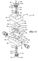
- Fig. 3 is a perspective exploded view of the optical flow cell;
- Fig. 4 is a perspective cross-sectional view of the optical flow cell;
- Fig. 5 is an elevational cross-sectional view of the optical flow cell;
- Fig. 6 is an enlarged cross-sectional view of a flow channel provided by the optical flow cell;
- Fig. 7 is a perspective cross-sectional view of the optical flow cell to show internal components more clearly;
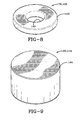
- Fig. 8 is a perspective view of a washer used in the optical flow cell; and
- Fig. 9 is a perspective view of a plate used in the optical flow cell.
- Referring now to the drawings, it can be seen that Fig. 1 shows an optical near-field imaging system designated generally by the
numeral 10. Thesystem 10 generally includes a detection andanalysis device 12, alight collimator 14, alight source 16, anoptical flow cell 18, and aflow delivery apparatus 20. Thissystem 10 is just one embodiment of the present concept and does not limit the scope of the claims in any way. - The
light source 16 is likely a laser or some other form of device that generates a collimated light beam. The light detection andanalysis device 12 is positioned to receive the beam generated by thelight source 16 and may include such detection components as a photo-detector, CMOS image array, or other device that is capable of performing imaging functions. The analysis component of thedevice 12 is coupled to the light detection component and analyzes the light received. The analysis component is most likely a microprocessor, general purpose CPU, DSP, FPGA, ASIC, or other similar device that is compatible with the light detection device. Theoptical flow cell 18 is interposed substantially between thelight source 16 and the detection andanalysis device 12. Theoptical flow cell 18 facilitates the flow of a fluid (e.g., engine oil) to enable optimum operation of thelight source 16 and the detection andanalysis device 12. Thesystem 10 also includes aflow delivery apparatus 20 for delivering the liquid to theflow cell 18. Thisflow delivery apparatus 20 may be a pump, a channel, or some other mechanism for delivering a fluid through theflow cell 18. Theflow delivery apparatus 20 may be connected to a piece of operating equipment. Thus, the system may be used with an engine or other piece of machinery while the machinery is operating. In other words, thesystem 10 can analyze and monitor the fluid in real-time as it is used by the machinery. - With this brief overview of the system in mind, particular embodiments for an
optical flow cell 18 are discussed in further detail in the following paragraphs. - Referring now to Figs. 2 and 3, it can be seen that the
flow cell 18 includes abody 24. Thebody 24 may be composed of acap block 26 and abase block 28. Thecap block 26 provides alight entry fixture 30 through which the system'slight source 16 may transmit light. Thebase block 28 provides animaging fixture 32 through which the system's light detector may detect light passing through the flow cell. In a preferred embodiment, these blocks are composed of type 430 stainless steel. Each block provides one or more aligned holes that may receivefasteners 34 therethrough. The blocks are secured to one another to maintain the positioning of the apertures with respect to one another and to facilitate the flow of fluid therethrough. - The
body 24 may include many other embodiments in addition to the particular embodiment in Figs 2 and 3. Various other embodiments may have a body made up of more than two blocks. Other embodiments may include blocks composed of other materials that may include, but are not limited to: stainless steel type 302, 304, 316, 321, 410, 420, and/or 440. Moreover, theblocks - Referring now to Figs. 3 and 4, the
cap block 26 includes anouter surface 42 opposite a facingsurface 44. Thesurfaces end surfaces 46 so as to form a substantially rectangular block. However, the shape of thecap block 26 is not critical to the operation of the optical flow cell. In any event, thecap block 26 provides across aperture 48, which is partially threaded, and which extends from theouter surface 42 toward the facingsurface 44. Aplate aperture 58 extends from the facing surface toward theouter surface 42. Theapertures plate aperture 58 has a somewhat smaller diameter than thecross aperture 48. Thecap block 26 also provides aplate aperture groove 60 which is recessed into the block and disposed annularly about theplate aperture 58. The facingsurface 44 provides aseal channel 62 which is disposed around theplate aperture 58. - The
flow cell body 24 may receive thelight entry fixture 30 that provides an opening through which the light source can direct the light. In a particular embodiment, thelight entry fixture 30 may include alight entry cap 64. Thelight entry cap 64, which may be at least partially threaded, is received in thecross aperture 48. Various embodiments may include alight entry cap 64 that provides acap head 66 with lateral screw holes 68 extending therethrough. The screw holes 68 receive setscrews 70 which are used to tighten upon any fixture inserted into thelight entry cap 64. Other various embodiments will not include screw holes 68 or setscrews 70. In particular, thelight entry cap 64 provides acap opening 72 which extends therethrough. Accordingly, thelight source 16 is routed into the light entry cap and retained in the cap opening by tightening theset screws 70 as needed. Thefixture 30 may also include alight entry washer 76, which has a washer opening 77 extending therethrough, is inserted into theplate aperture 58 such that the opening 77 is aligned with thecap opening 72. An o-ring 78 and abacking ring 80 are received in theplate aperture groove 60. Alight plate 82 is received in theplate aperture 58 and is shaped so as to allow for a press fit of theplate 82 into theaperture 58. The o-ring 78 and thebacking ring 80 are positioned around the outer diameter of the light plate. The light plate is positioned such that it is adjacent to or at least abuts thelight entry washer 76 at one end. The other end of thelight plate 82 is positioned substantially flush with the facingsurface 44. - The
base block 28, which is ideally made of the same material as thecap block 26, also provides anouter surface 86 which is opposite a facingsurface 88. When assembled, the blocks respective facing surfaces face or are adjacent to one another. Thesurfaces end surface 90 provides at least a partially threaded bore 92 which extends from the end surface inwardly. Extending further from each bore 92 is acorresponding inlet channel 94 and anoutlet channel 96. As best seen in Fig. 4, thechannels respective bore 92 toward the facingsurface 88. - The
base block 28, also provides a cross-aperture 98 which extends from theouter surface 86 toward the facingsurface 88. Aligned and substantially concentric with the cross-aperture 98 is aplate aperture 100 which extends from the facing surface toward theouter surface 86. The cross-aperture 98 is also partially threaded and has a somewhat larger diameter than theplate aperture 100. Theblock 28 also provides a plate aperture groove 102 which is recessed from theplate aperture 100 and disposed annularly about theaperture 100. - The
flow cell body 24 may receive alight imaging fixture 103 that provides an opening through which the light detector can receive the light. In a particular embodiment, the light imaging fixture may include alight imaging cap 104. Thelight imaging cap 104, which may be partially threaded, is received in the cross-aperture 98. Thelight imaging cap 104 has acap opening 106 extending therethrough and substantially aligned with theplate aperture 100. Alight entry washer 108 having a washer opening 109 therethrough is received in theplate aperture 100. An o-ring 110 and abacking ring 112 are received in the plate aperture groove 102 and seal around animaging plate 114 which is received in theplate aperture 100. Theimaging plate 114 is similar in construction to thelight plate 82, but has a slightly larger outer diameter so as to facilitate construction of the assembly. In any event, theplate aperture 100 may be sized and located so as to be medially positioned between theinlet channel 94 and theoutlet channel 96. In other words, thechannels surface 88 in close proximity to theplate aperture 100 but are not contiguous therewith. Theimaging plate 114 is contained within theplate aperture 100 by a press fit and the one end of the imaging plate is substantially flush with the facingsurface 88. The other end of theimaging plate 114 is placed adjacent to or abuts thelight entry washer 108 which in turn is adjacent to or abuts thelight imaging cap 104. - Referring now to Figs. 3 and 7, it can be seen that a series of components are interposed between the
cap block 26 and thebase block 28 so as to allow for a flow of fluid between the blocks as delivered by theflow delivery apparatus 20. In particular, theflow cell 18 includes anouter shim 120 which has a thickness of about 100 microns, and which has a plurality offastener openings 122 which allow thefasteners 34 to extend between and through theblocks shim 120 also provides one or more alignment openings 124 as well as amajor opening 126. Themajor opening 126 is sized to surround theseal channel 62 and, as shown, is substantially oval in shape. Themajor opening 126 also effectively surrounds the channels as they exit from the facing surface and the apertures provided by both of theblocks oval seal 128 is made from a polymeric material and is received in theseal channel 62. Theseal 128, with theblocks - An
inner shim 130, which has substantially the same thickness as theouter shim 120, provides one ormore alignment openings 132 extending therethrough. Theinner shim 130 provides a flow opening 134 wherein theinner shim 130 is sized to fit within theoval seal 128 and the flow opening 134 is sized to be contiguous with the inlet andoutlet channels plates blocks outer shim 120 and theinner shim 130. The alignment pins are used to maintain proper positioning of the shims in relation to the channels and to ensure that the flow opening 134 is aligned with the channels and plate apertures. When the blocks are assembled to one another, and the various washers and plates are positioned within the respective blocks, and the fasteners secure the blocks to one another aflow channel 138 is formed between theplates flow channel 138 is further defined by theflow opening 134. Theflow channel 138 transitions the flow fluid received through the inlet channel, and subsequently forms the fluid into a laminar flow such that the light detector and analysis device can function as they are intended. The flow of fluid then exits the outlet channel from theflow channel 138 and returns to the operational mechanism which is being monitored. - Referring now to Figs. 8 and 9, modifications are made to the plates and washers to allow the flow cell to withstand the temperature and pressure that the fluid exerts in the
flow channel 138. In particular, thewashers edges 140 and external chamfered edges 142. In a similar manner, theplates edges 144. Use of the chamfers on the washers and the plates distributes the forces or loads generated by the pressurized fluid flowing through thechannel 138. Unchamfered edges tend to increase pressure points and cause the plates and/or washers to break thereby destroying the integrity of the flow cell. - Attached to each end of the
block 28 is acoupling 150 that is threadingly received into each threaded bore 92. Eachcoupling 150 is connected to theflow delivery apparatus 20. The present concept is not limited to thecouplings 150 shown, but may include any other connection device used in this and similar arts. Various embodiments may not use a coupling at all. Moreover, the present concept includes alternative arrangements of thechannels channels cap block 28, this concept includes other embodiments in which bothchannels base block 26. And this concept also includes embodiments where one channel exists in one block and the other channel exists in the other block. Furthermore, the channels need not be on opposite sides of the flow cell. For example, alternative embodiments include those in which the inflow and outflow channels may exist on the same side of the blocks, and also include those embodiments where the channels exist at right angles (or any other angle) to one another. - The
flow cell 18 is configured for high pressure and high temperature applications. At these temperatures and pressures, steep gradients in pressure over an area (i.e., large forces) can cause internal damage to a part. Accordingly, one particular triumph of the current concept lies in its method of vertical assembly as shown in Figs. 3 and 4, which tends to minimize such large internal forces. Thus, one advantage of theflow cell 18 is that large internal forces are minimized. More specifically, the flow cell minimizes large forces acting on the two plates. Two major sources of stress often exist: high temperatures causing thermal expansion, and high-pressure oil exerting force on thelight entry plate 82 and theimaging plate 114. For example, consider an embodiment where the plates are made of glass. Glass is brittle, meaning that is does not flex an appreciable amount. To keep glass from fracturing, a preferred embodiment may choose the materials of the flow cell (gaskets, glass, aluminum washer, stainless steels) to match the coefficients of thermal expansion over a possible 140°C range at a maximum pressure (5000 psi). In other words, the coefficients of thermal expansion for thefixtures blocks flow channel 138 is maintained. Use of the chamfered washers and plates also maintains the flow channel's integrity. As a result, the imaging of the debris contained in the fluid is not adversely affected. - As shown in Figs. 5 and 6, a viewing region is located largely between the
light entry plate 82 and theimaging plate 114. A particular challenge in this region dealt with keeping the viewing region's depth constant over a wide range of temperatures and at high pressure. Ideally, the depth of this viewing region is 105 µm plus-or-minus 5 µm. This depth allows for the system to image typical particles, often of about 100 µm or less in size. - Other embodiments of the present concept may include flow cells having only an inner shim, only an outer shim, or no shims at all. Furthermore, the shape of any shims utilized is not limited to the shape of the shims in Fig. 7, but rather may extend to any shape that a person skilled in the art might utilize. Moreover, the shims are not limited to stainless steel, but may be composed of any substance that aids in meeting the high pressure and high temperature demands of the current part. Moreover, if shims are utilized, they are designed in light of the thermal expansion coefficients of any components of a vertical assembly as discussed above.
- High-pressure fluid may pass through the viewing region (see Figs. 5 and 6). Some common examples of a high-pressure fluid are lubricating oil (typically having a pressure of approximately 200 psi) and hydraulic oil (often having a pressure of about 5000 psi). When a high-pressure fluid passes through the viewing region, it presents several challenges. First, the fluid exerts pressure against the
light entry plate 82 and theimaging plate 114. Accordingly, these plates must be constructed so as to resist this high pressure oil. - The flow cell disclosed herein withstands the added stress experienced by parts at high temperatures and pressures. More particularly, over a wide temperature range and at high pressure, such a flow cell may maintain a relatively constant viewing region and maintain laminar flow across that viewing region. The materials of the flow cell (gaskets, glass, stainless steels, etc.) are chosen so that the coefficients of thermal expansion minimize internal stresses on the part over a temperature range of 140°C and at a pressure of 5000 psi.
- The present invention has a much wider scope of application than mere incorporation into automotive engines. For example, in the aircraft industry, predicting failure is critically important to avoid accidents and loss of life. Thus, system designers in the art would greatly benefit from the present invention. Most notably, these designers could use such a system in engines, hydraulic systems for brakes and landing gear, and many other parts of an airplane through which liquids pass. Furthermore, the present invention can be used with fluids other than engine oil. Indeed, other monitored fluids might include (but are not limited to) lubricating oils; hydraulic fluids; fluids used in industrial quality control, food processing, medical analysis, and environment control; as well as numerous others.
- Accordingly, one advantage of the
optical flow cell 18 is to maintain a relatively constant depth of fluid between the two optically transparent plates over a wide range of temperatures and pressures. In particular, the present concept strives to keep uniform laminar flow between the two optically transparent plates. Moreover, another advantage is to provide a flow cell that could be monitored over a network. For example, in oil rigs, windmills, or other systems that may be in remote locations and require relatively little maintenance, it may be useful to remotely monitor the fluids in the system and send a repairman only when maintenance is required. In addition, the repairman should already know the nature of the problem, and as such will only need limited equipment and limited time. Because "time is money," the present concept will also offer reduced costs for final maintenance. - Thus, it can be seen that the objects of the invention have been satisfied by the structure and its method for use presented above. While in accordance with the Patent Statutes, only the best mode and preferred embodiment has been presented and described in detail, it is to be understood that the invention is not limited thereto and thereby. Accordingly, for an appreciation of the true scope and breadth of the invention, reference should be made to the following claims.
Claims (12)
- An optical flow cell comprising:a flow cell body having an inlet and an outlet with a flow opening therebetween to allow a fluid to pass therethrough, said flow cell body having a thermal expansion rate; anda light entry fixture and a light imaging fixture carried by said flow cell body, said light entry fixture positioned at one side of said flow opening and said light imaging fixture positioned at an opposite side of said flow opening, said fixtures made from at least some materials different than said flow cell body but having said thermal expansion rate so as to maintain a predetermined size of said flow opening.
- The optical flow cell according to claim 1, wherein the flow cell body comprises:a base block; anda cap block coupled to said base block.
- The optical flow cell according to claim 2, further comprising:a shim positioned between said base block and said cap block; andwherein said shim forms an opening between said blocks.
- The optical flow cell according to claim 2, further comprising:an inner shim positioned between said base block and said cap block;an outer shim positioned between said base block and said cap block, wherein said outer shim is concentrically disposed outside of said inner shim; andan oval seal located between said inner shim and said outer shim, wherein at least one of said shims forms an opening between said blocks.
- The optical flow cell according to claim 4, wherein said body has an inlet and an outlet that fluidly communicate with at least a portion of said opening between said blocks.
- The optical flow cell according to claim 5, further comprising:couplings received in one of said blocks and linked to said inlet and said outlet.
- The optical flow cell according to claim 6, wherein said inlet and said outlet are in one of said blocks, and wherein said inlet and said outlet are angled into said opening between said blocks.
- The optical flow cell according to claim 2, wherein said light entry fixture is at least partially threaded and includes a cap opening which extends therethrough and a cap head with lateral screw holes extending therethrough, wherein said light imaging fixture is at least partially threaded and includes a cap opening which extends therethrough, and wherein said base block includes a cross aperture which is partially threaded and a plate aperture which is aligned with said cross aperture and is smaller than said cross aperture.
- The optical flow cell according to claim 8, further comprising:a light plate received in said plate aperture, wherein said light plate has chamfered edges.
- The optical flow cell of claim 9, wherein said base block provides
a recessed groove annularly disposed about said plate aperture;
a backing ring, positioned in said recessed groove; and
an o-ring positioned in said recessed groove, said backing ring and said o-ring disposed about said light plate. - The optical flow cell of claim 8, further comprising:a light imaging cap with a head, wherein said light imaging cap is at least partially threaded; anda light entry cap with a head, wherein said light entry cap is at least partially threaded.
- The optical flow cell of claim 2, further comprising:at least one fastener that holds said base block and said cap block together.
Applications Claiming Priority (1)
| Application Number | Priority Date | Filing Date | Title |
|---|---|---|---|
| US11/228,172 US7307717B2 (en) | 2005-09-16 | 2005-09-16 | Optical flow cell capable of use in high temperature and high pressure environment |
Publications (2)
| Publication Number | Publication Date |
|---|---|
| EP1764608A2 true EP1764608A2 (en) | 2007-03-21 |
| EP1764608A3 EP1764608A3 (en) | 2007-05-02 |
Family
ID=37562126
Family Applications (1)
| Application Number | Title | Priority Date | Filing Date |
|---|---|---|---|
| EP06254786A Withdrawn EP1764608A3 (en) | 2005-09-16 | 2006-09-14 | Optical flow cell capable of use in high temperature and high pressure environment |
Country Status (6)
| Country | Link |
|---|---|
| US (1) | US7307717B2 (en) |
| EP (1) | EP1764608A3 (en) |
| JP (1) | JP2007093598A (en) |
| CA (1) | CA2559425A1 (en) |
| FI (1) | FI20065558L (en) |
| IL (1) | IL178045A0 (en) |
Cited By (4)
| Publication number | Priority date | Publication date | Assignee | Title |
|---|---|---|---|---|
| EP2187209A1 (en) * | 2008-11-12 | 2010-05-19 | Roche Diagnostics GmbH | Hemolyser |
| GB2480153A (en) * | 2010-05-05 | 2011-11-09 | Valentine John Rossiter | Highly inert fluid-handling optical system |
| WO2018100032A1 (en) * | 2016-11-30 | 2018-06-07 | Ge Healthcare Bio-Sciences Ab | Optical flow cell |
| WO2019229201A1 (en) * | 2018-05-29 | 2019-12-05 | Ge Healthcare Bio-Sciences Ab | Optical flow cell |
Families Citing this family (21)
| Publication number | Priority date | Publication date | Assignee | Title |
|---|---|---|---|---|
| AU2006311518B2 (en) * | 2005-11-07 | 2013-01-31 | Jaleva Pharmaceuticals, Llc | Film-forming resins as a carrier for topical application of pharmacologically active agents |
| US7515259B2 (en) * | 2006-03-10 | 2009-04-07 | Dionex Corporation | Flow cell for optical detector and method of forming same |
| DE102006028516B3 (en) * | 2006-05-31 | 2007-10-04 | Hanno Wachernig | Cuvette for measuring particles of sample moving in cuvette comprises bearing with partial bearings for receiving forces running at angle to longitudinal axis through ends of cuvette |
| US7518720B2 (en) * | 2007-08-01 | 2009-04-14 | Lockheed Martin Corporation | Optical flow cell for use in high temperature and/or high pressure environments |
| EP2217376B1 (en) * | 2007-11-13 | 2013-01-09 | Roche Diagnostics GmbH | Cuvette and method for using said cuvette |
| EP2335079B1 (en) * | 2008-09-25 | 2015-07-01 | Agilent Technologies, Inc. | Light scattering flow cell device |
| US8564768B2 (en) * | 2009-04-17 | 2013-10-22 | Schlumberger Technology Corporation | High pressure and high temperature optical spectroscopy cell using spherical surfaced lenses in direct contact with a fluid pathway |
| JP5714977B2 (en) * | 2010-06-28 | 2015-05-07 | 株式会社堀場製作所 | Optical measuring device |
| JP5868626B2 (en) * | 2011-07-22 | 2016-02-24 | 株式会社 堀場アドバンスドテクノ | Optical measuring cell and optical analyzer |
| DE102013102440B3 (en) | 2013-03-12 | 2014-05-15 | Dionex Softron Gmbh | Positioning unit for flow cell for optical detection in HPLC field, has front end facing away from flow cell formed by outer surface of flange of cell, and terminal piece whose front end is connected with light conductor and sample supply |
| DE102013102438B3 (en) | 2013-03-12 | 2014-03-20 | Dionex Softron Gmbh | Flow cell for measuring e.g. permittivity of sample fluid in HPLC application, has capillary tubes arranged within protective tube to obviate unwanted mechanical application on side of capillary tubes surrounded along longitudinal direction |
| DE102013102439B4 (en) | 2013-03-12 | 2021-09-02 | Dionex Softron Gmbh | Process for the production of a fluidic connection component for chromatography |
| US9274041B2 (en) | 2014-04-15 | 2016-03-01 | Spectro Scientific, Inc. | Particle counter and classification system |
| EP3149450B1 (en) * | 2014-05-30 | 2019-05-15 | The Government of the United States of America as represented by the Secretary of the Navy | Method and apparatus for stabilizing the thickness of an optical channel for extended pressure environment |
| US9810616B2 (en) * | 2014-05-30 | 2017-11-07 | The United States Of America, As Represented By The Secretary Of The Navy | High pressure housing and optical viewing system |
| JP6280882B2 (en) * | 2015-02-18 | 2018-02-14 | アズビル株式会社 | Flow cell and manufacturing method of flow cell |
| US10288556B2 (en) * | 2016-04-21 | 2019-05-14 | Instrumentation Laboratory Company | Optical flow cell apparatus and method for reducing deflection of sample chamber |
| US10816450B2 (en) | 2017-12-18 | 2020-10-27 | Spectro Scientific, Inc. | Particle counter and classification system |
| US11674536B2 (en) | 2020-12-14 | 2023-06-13 | Caterpillar Inc. | Guide element for hydraulic fluid |
| CN114018769A (en) * | 2021-11-12 | 2022-02-08 | 米谱科技(常州)有限公司 | Liquid sample cell reaches particulate matter measuring apparatu including it |
| EP4565869A1 (en) * | 2022-08-01 | 2025-06-11 | Washington University | Flow cell and sampling probe |
Family Cites Families (37)
| Publication number | Priority date | Publication date | Assignee | Title |
|---|---|---|---|---|
| US3198064A (en) | 1961-06-29 | 1965-08-03 | Welch Allyn Inc | Blood sample holder |
| US3886264A (en) | 1972-11-06 | 1975-05-27 | Ethyl Corp | Process for hydrolyzing aluminum alkoxides using sulfurous acid |
| US3886364A (en) * | 1973-06-19 | 1975-05-27 | Union Carbide Corp | High pressure infrared cell |
| US3947121A (en) | 1973-07-30 | 1976-03-30 | Corning Glass Works | Method for aligning microstructures |
| GB2116704B (en) | 1977-09-23 | 1984-03-21 | Gamma Biologicals Inc | Electro-optical apparatus |
| US4393466A (en) | 1980-09-12 | 1983-07-12 | International Remote Imaging Systems | Method of analyzing particles in a dilute fluid sample |
| DE3233809A1 (en) | 1982-09-11 | 1984-03-15 | Boehringer Mannheim Gmbh, 6800 Mannheim | CUEVETTE FOR DETERMINING CHEMICAL COMPOUNDS IN LIQUIDS |
| JPH061241B2 (en) | 1985-11-11 | 1994-01-05 | キヤノン株式会社 | Particle analyzer |
| JPH0763464B2 (en) | 1986-05-07 | 1995-07-12 | 株式会社東芝 | X-ray CT system |
| US4804267A (en) | 1986-07-10 | 1989-02-14 | Scientific Imaging Instruments, Inc. | System for microscopically analyzing fluids |
| EP0302009A1 (en) | 1987-07-22 | 1989-02-01 | Ciba-Geigy Ag | Flow-through cuvette |
| ES2020001B3 (en) * | 1987-07-22 | 1991-07-16 | Ciba-Geigy Ag | PROCEDURAL CUVETTE |
| US5030421A (en) | 1988-08-31 | 1991-07-09 | Davstar Industries, Inc. | Integral centrifuge tube and specimen slide |
| US5098661A (en) | 1988-11-16 | 1992-03-24 | Medical Laboratory Automation, Inc. | Coded cuvette for use in testing apparatus |
| US5046854A (en) * | 1990-02-01 | 1991-09-10 | The Dow Chemical Company | Photometric cell and probe having windows fusion sealed to a metallic body |
| IT1247004B (en) | 1991-04-03 | 1994-12-12 | Ottica Ist Naz | METHOD AND MEASURING DEVICE FOR THE GRANULOMETRIC DISTRIBUTION OF SOLID PARTICULATE IN FLOW |
| DE69327182T2 (en) | 1992-02-18 | 2000-06-15 | Hitachi, Ltd. | Device and method for examining particles in a fluid |
| US5241189A (en) | 1992-05-29 | 1993-08-31 | Eastman Kodak Company | Ink concentration sensor for maintaining dye concentration in an ink jet printer |
| EP0644414B1 (en) | 1993-08-19 | 2001-11-21 | Hitachi, Ltd. | Classification and examination device of particles in fluid |
| JPH07120375A (en) | 1993-10-21 | 1995-05-12 | Hitachi Ltd | Flow type particle image analysis method and apparatus |
| US6049381A (en) | 1993-10-29 | 2000-04-11 | The United States Of America As Represented By The Secretary Of The Navy | Real time suspended particle monitor |
| JPH07218417A (en) | 1994-01-28 | 1995-08-18 | Hitachi Ltd | Particle analysis method |
| GB9404749D0 (en) | 1994-03-10 | 1994-04-27 | Ars Holding 89 Nv | Device for use in spectrophotometry |
| US5572320A (en) | 1994-11-17 | 1996-11-05 | The United States Of America As Represented By The Secretary Of The Navy | Fluid sampler utilizing optical near-field imaging |
| US5883721A (en) | 1997-07-11 | 1999-03-16 | Waters Investments Limited | Apparatus and process for measuring absorbance in fluid samples |
| US6069694A (en) * | 1998-05-29 | 2000-05-30 | Foss Nirsystems, Inc. | Flow cell |
| US6290912B1 (en) | 1998-07-14 | 2001-09-18 | Bayer Corporation | Read head for luminometer |
| DE19859479A1 (en) | 1998-12-22 | 1999-12-23 | Siemens Ag | Analysis cuvette non-dispersive infrared gas analysis unit |
| US6587195B1 (en) * | 1999-01-26 | 2003-07-01 | Axiom Analytical, Inc. | Method and apparatus for sealing an optical window in a spectroscopic measuring device |
| US6104483A (en) | 1999-06-18 | 2000-08-15 | Lockheed Martin Tactical Defense Systems, Inc. | Optical flow cell with references flange |
| EP1245945A3 (en) | 2001-03-28 | 2003-12-17 | Sysmex Corporation | Particle measurement method |
| US6873411B2 (en) | 2001-08-07 | 2005-03-29 | Lockheed Martin Corporation | Optical debris analysis fixture |
| JP2003322611A (en) * | 2002-04-30 | 2003-11-14 | Horiba Ltd | Measuring chamber equipped with optical window |
| US6894777B2 (en) * | 2002-08-07 | 2005-05-17 | Romaine R. Maiefski | Multiple-channel UV spectrometer assembly |
| US6771366B2 (en) | 2002-10-04 | 2004-08-03 | J.M. Canty Inc. | Fluid flow cell |
| US7245368B2 (en) * | 2003-03-31 | 2007-07-17 | C & L Instruments | Sample chamber for microscopy |
| US7355697B2 (en) * | 2004-08-26 | 2008-04-08 | The United States Of America As Represented By The Department Of Health And Human Services | Flow-through, thermal-expansion-compensated cell for light spectroscopy |
-
2005
- 2005-09-16 US US11/228,172 patent/US7307717B2/en not_active Expired - Lifetime
-
2006
- 2006-09-11 FI FI20065558A patent/FI20065558L/en unknown
- 2006-09-12 IL IL178045A patent/IL178045A0/en unknown
- 2006-09-12 CA CA002559425A patent/CA2559425A1/en not_active Abandoned
- 2006-09-14 EP EP06254786A patent/EP1764608A3/en not_active Withdrawn
- 2006-09-15 JP JP2006250779A patent/JP2007093598A/en not_active Withdrawn
Cited By (8)
| Publication number | Priority date | Publication date | Assignee | Title |
|---|---|---|---|---|
| EP2187209A1 (en) * | 2008-11-12 | 2010-05-19 | Roche Diagnostics GmbH | Hemolyser |
| US8279433B2 (en) | 2008-11-12 | 2012-10-02 | Roche Diagnostics Operating, Inc. | Haemolysator |
| GB2480153A (en) * | 2010-05-05 | 2011-11-09 | Valentine John Rossiter | Highly inert fluid-handling optical system |
| WO2018100032A1 (en) * | 2016-11-30 | 2018-06-07 | Ge Healthcare Bio-Sciences Ab | Optical flow cell |
| US12066375B2 (en) | 2016-11-30 | 2024-08-20 | Cytiva Sweden Ab | Optical flow cell |
| EP4462104A3 (en) * | 2016-11-30 | 2025-04-23 | Cytiva Sweden AB | Method of producing an optical flow cell |
| WO2019229201A1 (en) * | 2018-05-29 | 2019-12-05 | Ge Healthcare Bio-Sciences Ab | Optical flow cell |
| US11280722B2 (en) | 2018-05-29 | 2022-03-22 | Cytiva Sweden Ab | Optical flow cell |
Also Published As
| Publication number | Publication date |
|---|---|
| US7307717B2 (en) | 2007-12-11 |
| CA2559425A1 (en) | 2007-03-16 |
| JP2007093598A (en) | 2007-04-12 |
| IL178045A0 (en) | 2006-12-31 |
| EP1764608A3 (en) | 2007-05-02 |
| US20070064226A1 (en) | 2007-03-22 |
| FI20065558A7 (en) | 2007-03-17 |
| FI20065558L (en) | 2007-03-17 |
| FI20065558A0 (en) | 2006-09-11 |
Similar Documents
| Publication | Publication Date | Title |
|---|---|---|
| US7307717B2 (en) | Optical flow cell capable of use in high temperature and high pressure environment | |
| US7518720B2 (en) | Optical flow cell for use in high temperature and/or high pressure environments | |
| US9810616B2 (en) | High pressure housing and optical viewing system | |
| US7184141B2 (en) | Optical flow cell for tribological systems | |
| US9541492B2 (en) | Method and apparatus for stabilizing the thickness of an optical channel for extended pressure environments | |
| US9034178B2 (en) | Fluid filter assembly with sight glass | |
| CN101943565A (en) | Moving oil particle microscopic imaging system with double fiber-coupling LED light sources | |
| US6873411B2 (en) | Optical debris analysis fixture | |
| US20190083908A1 (en) | Disposable filter with an accessory port | |
| US7486071B2 (en) | Fluid monitoring arrangement | |
| EP1406079A2 (en) | Fluid flow cell | |
| US20180156086A1 (en) | Systems for in situ monitoring of working fluids and working fluid systems | |
| KR100356639B1 (en) | Device for measuring oil contamination | |
| US20070017280A1 (en) | Wear monitoring | |
| US20030209647A1 (en) | Temperature compensating optical debris analysis fixture | |
| US6047591A (en) | Corrosion ring gauge and method | |
| Fitch | Elements of a successful oil analysis program-part 1 | |
| Reintjes et al. | Advances in Comprehensive Fluid Analysis. | |
| WO2017145768A1 (en) | Particle detection device | |
| Newman | Evaluations of Commercial Induction Air Monitors and Go/No-Go Oil Quality Testers as Built-In Test Equipment (BITE). | |
| Fitch | 5 Control and Management | |
| Nelson et al. | Expediting Engine Development Through Near Time Oil Analysis | |
| Pflumm et al. | Utilizing Dynamic Fuel Pressure Sensor For Detecting Bearing Spalling and Gear Pump Failure Modes in Cummins Pressure Time (PT) Pumps |
Legal Events
| Date | Code | Title | Description |
|---|---|---|---|
| PUAI | Public reference made under article 153(3) epc to a published international application that has entered the european phase |
Free format text: ORIGINAL CODE: 0009012 |
|
| AK | Designated contracting states |
Kind code of ref document: A2 Designated state(s): AT BE BG CH CY CZ DE DK EE ES FI FR GB GR HU IE IS IT LI LT LU LV MC NL PL PT RO SE SI SK TR |
|
| AX | Request for extension of the european patent |
Extension state: AL BA HR MK YU |
|
| PUAL | Search report despatched |
Free format text: ORIGINAL CODE: 0009013 |
|
| AK | Designated contracting states |
Kind code of ref document: A3 Designated state(s): AT BE BG CH CY CZ DE DK EE ES FI FR GB GR HU IE IS IT LI LT LU LV MC NL PL PT RO SE SI SK TR |
|
| AX | Request for extension of the european patent |
Extension state: AL BA HR MK YU |
|
| 17P | Request for examination filed |
Effective date: 20071023 |
|
| 17Q | First examination report despatched |
Effective date: 20071126 |
|
| AKX | Designation fees paid |
Designated state(s): AT BE BG CH CY CZ DE DK EE ES FI FR GB GR HU IE IS IT LI LT LU LV MC NL PL PT RO SE SI SK TR |
|
| STAA | Information on the status of an ep patent application or granted ep patent |
Free format text: STATUS: THE APPLICATION IS DEEMED TO BE WITHDRAWN |
|
| 18D | Application deemed to be withdrawn |
Effective date: 20100401 |