EP1764482A2 - Single piece nozzle wheel and manufacturing method - Google Patents
Single piece nozzle wheel and manufacturing method Download PDFInfo
- Publication number
- EP1764482A2 EP1764482A2 EP06254488A EP06254488A EP1764482A2 EP 1764482 A2 EP1764482 A2 EP 1764482A2 EP 06254488 A EP06254488 A EP 06254488A EP 06254488 A EP06254488 A EP 06254488A EP 1764482 A2 EP1764482 A2 EP 1764482A2
- Authority
- EP
- European Patent Office
- Prior art keywords
- wheel
- radially inner
- integrated nozzle
- stock material
- nozzle
- Prior art date
- Legal status (The legal status is an assumption and is not a legal conclusion. Google has not performed a legal analysis and makes no representation as to the accuracy of the status listed.)
- Withdrawn
Links
Images



Classifications
-
- F—MECHANICAL ENGINEERING; LIGHTING; HEATING; WEAPONS; BLASTING
- F01—MACHINES OR ENGINES IN GENERAL; ENGINE PLANTS IN GENERAL; STEAM ENGINES
- F01D—NON-POSITIVE DISPLACEMENT MACHINES OR ENGINES, e.g. STEAM TURBINES
- F01D9/00—Stators
- F01D9/02—Nozzles; Nozzle boxes; Stator blades; Guide conduits, e.g. individual nozzles
- F01D9/04—Nozzles; Nozzle boxes; Stator blades; Guide conduits, e.g. individual nozzles forming ring or sector
-
- F—MECHANICAL ENGINEERING; LIGHTING; HEATING; WEAPONS; BLASTING
- F01—MACHINES OR ENGINES IN GENERAL; ENGINE PLANTS IN GENERAL; STEAM ENGINES
- F01D—NON-POSITIVE DISPLACEMENT MACHINES OR ENGINES, e.g. STEAM TURBINES
- F01D25/00—Component parts, details, or accessories, not provided for in, or of interest apart from, other groups
- F01D25/24—Casings; Casing parts, e.g. diaphragms, casing fastenings
- F01D25/243—Flange connections; Bolting arrangements
-
- F—MECHANICAL ENGINEERING; LIGHTING; HEATING; WEAPONS; BLASTING
- F01—MACHINES OR ENGINES IN GENERAL; ENGINE PLANTS IN GENERAL; STEAM ENGINES
- F01D—NON-POSITIVE DISPLACEMENT MACHINES OR ENGINES, e.g. STEAM TURBINES
- F01D5/00—Blades; Blade-carrying members; Heating, heat-insulating, cooling or antivibration means on the blades or the members
- F01D5/12—Blades
- F01D5/14—Form or construction
- F01D5/147—Construction, i.e. structural features, e.g. of weight-saving hollow blades
-
- F—MECHANICAL ENGINEERING; LIGHTING; HEATING; WEAPONS; BLASTING
- F01—MACHINES OR ENGINES IN GENERAL; ENGINE PLANTS IN GENERAL; STEAM ENGINES
- F01D—NON-POSITIVE DISPLACEMENT MACHINES OR ENGINES, e.g. STEAM TURBINES
- F01D5/00—Blades; Blade-carrying members; Heating, heat-insulating, cooling or antivibration means on the blades or the members
- F01D5/34—Rotor-blade aggregates of unitary construction, e.g. formed of sheet laminae
-
- F—MECHANICAL ENGINEERING; LIGHTING; HEATING; WEAPONS; BLASTING
- F01—MACHINES OR ENGINES IN GENERAL; ENGINE PLANTS IN GENERAL; STEAM ENGINES
- F01D—NON-POSITIVE DISPLACEMENT MACHINES OR ENGINES, e.g. STEAM TURBINES
- F01D9/00—Stators
- F01D9/02—Nozzles; Nozzle boxes; Stator blades; Guide conduits, e.g. individual nozzles
Definitions
- This invention relates generally to steam turbine construction and, more specifically, to an integrated nozzle wheel construction for a reaction steam turbine.
- the nozzle manufacturing/assembly process is simplified, and the overall cost of the reaction steam path is reduced without impacting the integrity of the overall reaction steam turbine design.
- a full row of reaction nozzles is machined into a 360° piece of flat stock material.
- the stock material may be forged, rolled ring or plate stock.
- the 360° ring is placed into a machining center where the ID, OD, inlet blends, airfoils, airfoil radii, cover shroud sealing configuration, retention features and the balance of the standard nozzle features are machined.
- the integrated nozzle wheel may or may not be split into two or more arcuate segments in preparation for the final steam path assembly process.
- the present invention relates to an integrated nozzle wheel for a turbine stator component comprising a three hundred sixty degree wheel formed from a single piece of stock material, a radially inner portion of the wheel machined to include a plurality of nozzles, each having an airfoil portion and a radially inner tip shroud portion; a radially outer portion of the wheel machined to include one or more assembly features.
- the invention in another aspect, relates to an integrated nozzle wheel for a turbine stator component comprising a three hundred sixty degree wheel formed from a single piece of stock material, a radially inner portion of the wheel machined to include a plurality of nozzles, each having an airfoil portion and a radially inner tip shroud portion; an outer portion of the wheel machined to include one or more assembly features; wherein the outer portion is formed with a plurality of bolt holes; wherein the bolt holes are circumferentially spaced about the outer portion; and wherein the wheel is split into two or more arcuate segments.
- the invention in still another aspect, relates to a turbine stator comprising a plurality of nozzle wheels assembled within a turbine casing, the nozzle wheels and the turbine casing split into upper and lower components, respectively, each nozzle wheel comprising a three hundred sixty degree wheel formed from a single piece of stock material, a radially inner portion of each nozzle wheel machined to include a plurality of nozzles; a radially outer portion of the wheel machined to include one or more assembly features.
- the invention in still another aspect, relates to a method of making a turbine nozzle wheel comprising forming flat stock material into an annular ring; machining a radially inner portion of the annular ring to include a plurality of nozzles, each having an airfoil portion, and a radially outer portion of the annular ring to include assembly features.
- an integrated nozzle wheel 10 is shown, split into upper and lower 180° segments or halves 12, 14. It will be appreciated that splitting the wheel facilitates assembly in the upper and lower turbine casing components or sections, with the nozzle wheel segments surrounding the rotor.
- the wheel 10 is manufactured from a single 360° piece of flat stock material that could be forged, rolled ring or plate stock.
- the annular ring is thereafter machined to include a plurality of airfoils 16, in a circumferential array at the radially inner portion of the wheel.
- the radially inner ends of the airfoils 16 are also machined to include an integral cover shroud sealing configuration 18 that determines the ID of the wheel.
- the remainder of the wheel, specifically the radially outer portion 20, is formed to include assembly bolt or tie-rod holes 22 and any other rim or rabbet configuration to facilitate axial stacking with similar wheels, or with discrete spacer rings therebetween that accommodate the rotating stages on the rotor.
- Figure 2 illustrates another integrated nozzle wheel 24 where one side 26 of the wheel is machined to include a blended toroidal-shaped inlet 28 extending axially upstream of the integrated nozzles 30.
- bolt or tie-rod holes 32 are provided in the radially outer region 34 to facilitate axial stacking.
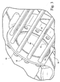
- Figure 3 illustrates the nozzle wheel 10 of Figure 1 located in a lower turbine casing component 36 with a plurality of tie rods or bolts 38 extending through the holes 22 and secured by nuts 40 or the like to facilitate axial stacking of multiple nozzle wheels.
- Figure 4 illustrates the arrangement in Figure 3 but with an upper casing component 42 assembled over the lower casing component 32. It will be appreciated that the upper and lower nozzle wheel segments 12, 14 and the upper and lower casing components 36, 42 will be secured, respectively, to each other, using conventional retention/securement hardware configurations (not shown). In the case of the nozzle wheel segments, the retention/securement features will be machined into the segments consistent with the invention described herein.
Landscapes
- Engineering & Computer Science (AREA)
- Mechanical Engineering (AREA)
- General Engineering & Computer Science (AREA)
- Architecture (AREA)
- Ceramic Engineering (AREA)
- Turbine Rotor Nozzle Sealing (AREA)
Abstract
Description
- This invention relates generally to steam turbine construction and, more specifically, to an integrated nozzle wheel construction for a reaction steam turbine.
- Current integral-cover reaction nozzle stages are made up of large quantities of individual reaction nozzles that are assembled into a machined stator casting or nozzle carrier. More specifically, individual nozzles are loaded into a dovetail groove and secured within the carrier using individual radial loading pins. Each nozzle tip is machined with a specified tip seal configuration for interaction with the turbine rotor so as to minimize leakage along the hot gas path. The time and cost associated with the manufacture of the stator casting, stator machining, nozzle stock material, nozzle machining and stator assembly add significant costs overall to the reaction steam path.
- In accordance with an exemplary embodiment of this invention, the nozzle manufacturing/assembly process is simplified, and the overall cost of the reaction steam path is reduced without impacting the integrity of the overall reaction steam turbine design.
- In the exemplary embodiment, a full row of reaction nozzles is machined into a 360° piece of flat stock material. It will be understood that the stock material may be forged, rolled ring or plate stock. The 360° ring is placed into a machining center where the ID, OD, inlet blends, airfoils, airfoil radii, cover shroud sealing configuration, retention features and the balance of the standard nozzle features are machined. Thereafter, the integrated nozzle wheel may or may not be split into two or more arcuate segments in preparation for the final steam path assembly process.
- It is also possible to incorporate into the integrated nozzle wheel, adjacent stator surfaces that are forward and/or aft of the nozzle airfoils and utilized to facilitate axial stacking of plural nozzle wheels in an alternating arrangement with rotor stage wheels.
- Accordingly, in one aspect, the present invention relates to an integrated nozzle wheel for a turbine stator component comprising a three hundred sixty degree wheel formed from a single piece of stock material, a radially inner portion of the wheel machined to include a plurality of nozzles, each having an airfoil portion and a radially inner tip shroud portion; a radially outer portion of the wheel machined to include one or more assembly features.
- In another aspect, the invention relates to an integrated nozzle wheel for a turbine stator component comprising a three hundred sixty degree wheel formed from a single piece of stock material, a radially inner portion of the wheel machined to include a plurality of nozzles, each having an airfoil portion and a radially inner tip shroud portion; an outer portion of the wheel machined to include one or more assembly features; wherein the outer portion is formed with a plurality of bolt holes; wherein the bolt holes are circumferentially spaced about the outer portion; and wherein the wheel is split into two or more arcuate segments.
- In still another aspect, the invention relates to a turbine stator comprising a plurality of nozzle wheels assembled within a turbine casing, the nozzle wheels and the turbine casing split into upper and lower components, respectively, each nozzle wheel comprising a three hundred sixty degree wheel formed from a single piece of stock material, a radially inner portion of each nozzle wheel machined to include a plurality of nozzles; a radially outer portion of the wheel machined to include one or more assembly features.
- In still another aspect, the invention relates to a method of making a turbine nozzle wheel comprising forming flat stock material into an annular ring; machining a radially inner portion of the annular ring to include a plurality of nozzles, each having an airfoil portion, and a radially outer portion of the annular ring to include assembly features.
- The invention will now be described in greater detail, by way of example, with reference to the drawings, in which:-
-
- FIGURE 1 is a perspective view of an integrated nozzle wheel in accordance with an exemplary embodiment of the invention;
- FIGURE 2 is a perspective view of another integrated nozzle wheel in accordance with the invention;
- FIGURE 3 is a perspective view of the nozzle wheel of Figure 1 assembled in a lower turbine casing component; and
- FIGURE 4 is a perspective view similar to Figure 3, but with an upper turbine casing component located over the upper nozzle wheel segment.
- With initial reference to Figure 1, an integrated
nozzle wheel 10 is shown, split into upper and lower 180° segments orhalves - In the exemplary embodiment, the
wheel 10 is manufactured from a single 360° piece of flat stock material that could be forged, rolled ring or plate stock. The annular ring is thereafter machined to include a plurality ofairfoils 16, in a circumferential array at the radially inner portion of the wheel. The radially inner ends of theairfoils 16 are also machined to include an integral covershroud sealing configuration 18 that determines the ID of the wheel. The remainder of the wheel, specifically the radiallyouter portion 20, is formed to include assembly bolt or tie-rod holes 22 and any other rim or rabbet configuration to facilitate axial stacking with similar wheels, or with discrete spacer rings therebetween that accommodate the rotating stages on the rotor. - Figure 2 illustrates another integrated
nozzle wheel 24 where oneside 26 of the wheel is machined to include a blended toroidal-shaped inlet 28 extending axially upstream of the integratednozzles 30. Here again, bolt or tie-rod holes 32 are provided in the radiallyouter region 34 to facilitate axial stacking. - Figure 3 illustrates the
nozzle wheel 10 of Figure 1 located in a lowerturbine casing component 36 with a plurality of tie rods orbolts 38 extending through theholes 22 and secured bynuts 40 or the like to facilitate axial stacking of multiple nozzle wheels. - Figure 4 illustrates the arrangement in Figure 3 but with an
upper casing component 42 assembled over thelower casing component 32. It will be appreciated that the upper and lowernozzle wheel segments lower casing components
Claims (11)
- An integrated nozzle wheel for a turbine stator component comprising a three hundred sixty degree wheel formed from a single piece of stock material, a radially inner portion of said wheel manufactured to include a plurality of nozzles, each having an airfoil portion and a radially inner tip shroud portion; a radially outer portion of said wheel manufactured to include one or more assembly features.
- The integrated nozzle wheel of claim 1 wherein said assembly features include a plurality of tie-rod or bolt holes.
- The integrated nozzle wheel of claim 2 wherein said tie-rod or bolt holes are circumferentially spaced about said radially outer portion.
- The integrated nozzle wheel of any preceding claim wherein said wheel is split into two or more arcuate segments.
- The integrated nozzle wheel of any preceding claim wherein said stock material comprises a forged stock.
- The integrated nozzle wheel of any one of claims 1 to 4 wherein said stock material comprises rolled ring stock.
- The integrated nozzle wheel of any one of claims 1 to 4 wherein said stock material comprises generally flat plate stock.
- An integrated nozzle wheel for a turbine stator component comprising a three hundred sixty degree wheel formed from a single piece of stock material, a radially inner portion of said wheel machined to include a plurality of nozzles, each having an airfoil portion and a radially inner tip shroud portion; an outer portion of said wheel machined to include a plurality of tie-rod or bolt holes circumferentially spaced about said outer portion; and wherein said wheel is split into a pair of 180° arcuate segments.
- A method of making a turbine nozzle wheel comprising forming stock material into an annular ring; machining a radially inner portion of said annular ring to include a plurality of nozzles, each having an airfoil portion, and a radially outer portion of said annular ring to include assembly features.
- The method of claim 9 wherein said assembly features include a plurality of circumferentially spaced tie-rod or bolt holes.
- The method of claim 9 or 10 including machining shroud covers on radially inner tips of said nozzle/airfoil portions.
Applications Claiming Priority (1)
| Application Number | Priority Date | Filing Date | Title |
|---|---|---|---|
| US11/219,667 US20070053773A1 (en) | 2005-09-07 | 2005-09-07 | Integrated nozzle wheel for reaction steam turbine stationary components and related method |
Publications (2)
| Publication Number | Publication Date |
|---|---|
| EP1764482A2 true EP1764482A2 (en) | 2007-03-21 |
| EP1764482A3 EP1764482A3 (en) | 2010-05-05 |
Family
ID=37490216
Family Applications (1)
| Application Number | Title | Priority Date | Filing Date |
|---|---|---|---|
| EP06254488A Withdrawn EP1764482A3 (en) | 2005-09-07 | 2006-08-29 | Single piece nozzle wheel and manufacturing method |
Country Status (5)
| Country | Link |
|---|---|
| US (1) | US20070053773A1 (en) |
| EP (1) | EP1764482A3 (en) |
| JP (1) | JP2007071209A (en) |
| KR (1) | KR20070028254A (en) |
| CN (1) | CN1928326A (en) |
Cited By (1)
| Publication number | Priority date | Publication date | Assignee | Title |
|---|---|---|---|---|
| EP1722070A3 (en) * | 2005-04-27 | 2011-10-12 | General Electric Company | Method of manufacturing segmented stators for a steam turbine |
Families Citing this family (4)
| Publication number | Priority date | Publication date | Assignee | Title |
|---|---|---|---|---|
| US7497658B2 (en) * | 2005-11-11 | 2009-03-03 | General Electric Company | Stacked reaction steam turbine stator assembly |
| KR100988582B1 (en) * | 2008-01-07 | 2010-10-18 | 더블유비엠과학기술 주식회사 | Steam turbine |
| KR100911765B1 (en) * | 2008-01-07 | 2009-08-10 | 더블유비엠과학기술 주식회사 | Nozzle Plates for Steam Turbines |
| KR101625794B1 (en) | 2015-04-06 | 2016-05-30 | 두산중공업 주식회사 | Nozzle box for turbine |
Family Cites Families (11)
| Publication number | Priority date | Publication date | Assignee | Title |
|---|---|---|---|---|
| US3091383A (en) * | 1957-02-14 | 1963-05-28 | Stalker Corp | Bladed rotor for fluid machines |
| US3300180A (en) * | 1964-11-17 | 1967-01-24 | Worthington Corp | Segmented diaphragm assembly |
| SE406625B (en) * | 1977-07-12 | 1979-02-19 | Stal Laval Turbin Ab | TURBOMASKIN |
| US5772401A (en) * | 1995-10-13 | 1998-06-30 | Dresser-Rand Company | Diaphragm construction for turbomachinery |
| US5655876A (en) * | 1996-01-02 | 1997-08-12 | General Electric Company | Low leakage turbine nozzle |
| US6095750A (en) * | 1998-12-21 | 2000-08-01 | General Electric Company | Turbine nozzle assembly |
| AU5006900A (en) * | 1999-05-13 | 2000-12-05 | Rolls-Royce Corporation | Method for designing a cyclic symmetric structure |
| US6425738B1 (en) * | 2000-05-11 | 2002-07-30 | General Electric Company | Accordion nozzle |
| US7004720B2 (en) * | 2003-12-17 | 2006-02-28 | Pratt & Whitney Canada Corp. | Cooled turbine vane platform |
| US20060245923A1 (en) * | 2005-04-27 | 2006-11-02 | General Electric Company | Arcuate nozzle segment and related method of manufacture |
| US7270512B2 (en) * | 2005-08-24 | 2007-09-18 | General Electric Company | Stacked steampath and grooved bucket wheels for steam turbines |
-
2005
- 2005-09-07 US US11/219,667 patent/US20070053773A1/en not_active Abandoned
-
2006
- 2006-08-29 EP EP06254488A patent/EP1764482A3/en not_active Withdrawn
- 2006-09-06 KR KR1020060085811A patent/KR20070028254A/en not_active Withdrawn
- 2006-09-07 CN CNA2006101518028A patent/CN1928326A/en active Pending
- 2006-09-07 JP JP2006242823A patent/JP2007071209A/en not_active Withdrawn
Cited By (1)
| Publication number | Priority date | Publication date | Assignee | Title |
|---|---|---|---|---|
| EP1722070A3 (en) * | 2005-04-27 | 2011-10-12 | General Electric Company | Method of manufacturing segmented stators for a steam turbine |
Also Published As
| Publication number | Publication date |
|---|---|
| KR20070028254A (en) | 2007-03-12 |
| EP1764482A3 (en) | 2010-05-05 |
| CN1928326A (en) | 2007-03-14 |
| US20070053773A1 (en) | 2007-03-08 |
| JP2007071209A (en) | 2007-03-22 |
Similar Documents
| Publication | Publication Date | Title |
|---|---|---|
| US5302086A (en) | Apparatus for retaining rotor blades | |
| US8727719B2 (en) | Annular flange for fastening a rotor or stator element in a turbomachine | |
| US7470113B2 (en) | Split knife edge seals | |
| US9453425B2 (en) | Turbine diaphragm construction | |
| CN101377131B (en) | Turbine rotor apparatus and system | |
| EP3123002B1 (en) | Stator vane support system within a gas turbine engine | |
| US10662793B2 (en) | Turbine wheel cover-plate mounted gas turbine interstage seal | |
| US20110164965A1 (en) | Steam turbine stationary component seal | |
| CA2837446C (en) | Attaching the blades to the drum of an axial turbocompressor | |
| WO2013138041A1 (en) | Arrangement for delivering combustion gas | |
| US20150098802A1 (en) | Shrouded turbine blisk and method of manufacturing same | |
| US9371742B2 (en) | Set of rotor disks for a turbine engine | |
| US9494042B2 (en) | Sealing ring for a turbine stage of an aircraft turbomachine, comprising slotted anti-rotation pegs | |
| US20200189044A1 (en) | Retaining device for disassembling a bladed wheel of a turbine engine and method employing it | |
| EP2957721B1 (en) | Turbine section of a gas turbine engine, with disk cooling and an interstage seal having a particular geometry | |
| EP1764482A2 (en) | Single piece nozzle wheel and manufacturing method | |
| US9828866B2 (en) | Methods and systems for securing turbine nozzles | |
| EP2586971B1 (en) | A spacer, a rotor, a spool and a method of orienting a rotor stack load path | |
| WO2011151329A1 (en) | Steam turbine assembly and method of assembling a steam turbine | |
| US20070071605A1 (en) | Integrated nozzle and bucket wheels for reaction steam turbine stationary components and related method | |
| US20170218778A1 (en) | Rotor for turbine engine comprising blades with added platforms | |
| EP3260663B1 (en) | Axial flow turbine diaphragm construction | |
| KR20070028256A (en) | Method for manufacturing integral bucket wheel and turbine bucket wheel | |
| US8282349B2 (en) | Steam turbine rotor and method of assembling the same | |
| US20080050226A1 (en) | Methods and apparatus for fabricating a rotor for a steam turbine |
Legal Events
| Date | Code | Title | Description |
|---|---|---|---|
| PUAI | Public reference made under article 153(3) epc to a published international application that has entered the european phase |
Free format text: ORIGINAL CODE: 0009012 |
|
| AK | Designated contracting states |
Kind code of ref document: A2 Designated state(s): AT BE BG CH CY CZ DE DK EE ES FI FR GB GR HU IE IS IT LI LT LU LV MC NL PL PT RO SE SI SK TR |
|
| AX | Request for extension of the european patent |
Extension state: AL BA HR MK YU |
|
| PUAL | Search report despatched |
Free format text: ORIGINAL CODE: 0009013 |
|
| AK | Designated contracting states |
Kind code of ref document: A3 Designated state(s): AT BE BG CH CY CZ DE DK EE ES FI FR GB GR HU IE IS IT LI LT LU LV MC NL PL PT RO SE SI SK TR |
|
| AX | Request for extension of the european patent |
Extension state: AL BA HR MK RS |
|
| AKY | No designation fees paid | ||
| REG | Reference to a national code |
Ref country code: DE Ref legal event code: 8566 |
|
| STAA | Information on the status of an ep patent application or granted ep patent |
Free format text: STATUS: THE APPLICATION IS DEEMED TO BE WITHDRAWN |
|
| 18D | Application deemed to be withdrawn |
Effective date: 20101106 |