EP1763268A1 - Dynamic sub-channel allocation in a OFDM/TDMA TDD communication system - Google Patents
Dynamic sub-channel allocation in a OFDM/TDMA TDD communication system Download PDFInfo
- Publication number
- EP1763268A1 EP1763268A1 EP05019885A EP05019885A EP1763268A1 EP 1763268 A1 EP1763268 A1 EP 1763268A1 EP 05019885 A EP05019885 A EP 05019885A EP 05019885 A EP05019885 A EP 05019885A EP 1763268 A1 EP1763268 A1 EP 1763268A1
- Authority
- EP
- European Patent Office
- Prior art keywords
- sub
- channel
- communication
- busy
- transmitter
- Prior art date
- Legal status (The legal status is an assumption and is not a legal conclusion. Google has not performed a legal analysis and makes no representation as to the accuracy of the status listed.)
- Granted
Links
Images






Classifications
-
- H—ELECTRICITY
- H04—ELECTRIC COMMUNICATION TECHNIQUE
- H04L—TRANSMISSION OF DIGITAL INFORMATION, e.g. TELEGRAPHIC COMMUNICATION
- H04L27/00—Modulated-carrier systems
- H04L27/26—Systems using multi-frequency codes
- H04L27/2601—Multicarrier modulation systems
- H04L27/2626—Arrangements specific to the transmitter only
-
- H—ELECTRICITY
- H04—ELECTRIC COMMUNICATION TECHNIQUE
- H04W—WIRELESS COMMUNICATION NETWORKS
- H04W72/00—Local resource management
- H04W72/50—Allocation or scheduling criteria for wireless resources
- H04W72/54—Allocation or scheduling criteria for wireless resources based on quality criteria
- H04W72/542—Allocation or scheduling criteria for wireless resources based on quality criteria using measured or perceived quality
Definitions
- the present invention is in the field of dynamic sub-channel allocation and medium access control (MAC), for example for multi user access in cellular, ad hoc and multi-hop based networks.
- MAC medium access control
- OFDM Orthogonal Frequency Division Multiplexing
- CCI co-channel interference
- channel sensing or random MAC protocols such as CSMA-CA (Carrier Sensing Multiple Access - Collision Avoidance).
- CSMA-CA Carrier Sensing Multiple Access - Collision Avoidance
- the present invention provides a method for a dynamic sub-channel allocation for communication between a transmitter and a receiver in a communication system comprising a communication channel having a plurality of sub-channels, the method comprising: receiving at the transmitter from the plurality of sub-channels respective busy-signals, each busy-signal being indicative of a communication on the respective sub-channel in the communication system, and selecting one or more sub-channels for a communication between the transmitter and the receiver by allocating a sub-channel for the communication, in case the busy-signal received from the sub-channel is equal to or greater than a first predetermined threshold and the sub-channel was used for a communication between the transmitter and the receiver in a preceding communication interval, or the busy-signal received from the sub-channel is equal to or less than a second predetermined threshold and the sub-channel was not used for a communication between the transmitter and the receiver in a preceding communication interval.
- the present invention provides a computer program having a program code for performing the inventive method, when the program runs on a computer.
- the present invention provides a transmitter for dynamic sub-channel allocation for communication with a receiver in a communication system comprising a communication channel having a plurality of sub-channels, the transmitter comprising: a means for receiving from the plurality of sub-channels respective busy-signals, each busy-signal being indicative of a communication on the respective sub-channel in the communication system, and a controller for selecting one or more sub-channels for a communication between the transmitter and the receiver by allocating a sub-channel for the communication, in case the busy-signal received from the sub-channel is equal to or greater than a first predetermined threshold and the sub-channel was used for a communication between the transmitter and the receiver in a preceding communication interval, or the busy-signal received from the sub-channel is equal to or less than a second predetermined threshold and the sub-channel was not used for a communication between the transmitter and the receiver in a preceding communication interval.
- the present invention provides a receiver for communication with a transmitter operative for dynamic sub-channel allocation in a communication system comprising a communication channel having a plurality of sub-channels, the receiver comprising: a means for receiving signals over a sub-channel allocated for communication by the transmitter, a means for generating a busy-signal on the sub-channel allocated for communication by the transmitter in case the signals received over this allocated sub-channel are equal to or greater than a predetermined threshold.
- the present invention provides a system for communication comprising the inventive transmitter and the inventive receiver.
- the present invention is based on the finding that an improvement of the dynamic sub-channel allocation can be achieved by dividing the communication channel into a plurality of sub-channels. Smaller sub-channels are less frequency selective and their channel transfer function can be much better approximated or modelled. Therefore, adaptive coding and modulation concepts can now be applied.
- TDD Time Division Duplexing
- Measuring the interference of a complete channel versus measuring the interference of sub-channels has a two-fold disadvantage.
- the inventive method provides more accurate distortion decisions and finally achieves improved spectral efficiency in a multi-user, multi-cell environment compared to the prior art.
- an OFDM-TDD based air-interface is used.
- the inventive method uses a dynamic sub-channel selection algorithm which involves a physical as well as a MAC (Medium Access Control) layer by exploiting channel reciprocity in TDD, and uses furthermore busy-tone signalling on time-multiplexed sub-channels.
- MAC Medium Access Control
- Channel reciprocity of TDD means that a potential interference from, for example, a first mobile station MS Tx transmitting data to a second mobile station MS Rx receiving data is identical to the interference the second mobile station MS Rx transmitting data would impose on the first mobile station MS Tx receiving data provided that the transmit powers are the same.
- the inventive method enables a frequency re-use of one, or in other words a frequency re-use of 100%, and basically results in a dynamic FDMA (Frequency Division Multiple Access) component in an OFDM-based air-interface.
- Clusters of sub carriers, or chunks are assigned for data transmission between a transmitter and a receiver only if these sub-channels cause negligible interference to potential victim receivers, i.e. only if the interference link is deeply faded or attenuated.
- channel sensing by means of busy-tone signalling is used.
- a short signal send out for example, by the receiver of the intended mobile station (MS) can be used by a dislocated potential interfering transmitter to determine the interference power it would cause to that receiver given that the transmit power of the busy-signal is a priori known by the potential interfering transmitter. This particular mechanism is exploited in this invention. Additionally, provision is made for an adaptive sub-channel assignment when the channel is slowly time varying.
- the inventive method therefore, offers the following advantages: high spectral efficiency in a multi-user, multi-cell environment for broadband wireless access, no requirement for a central radio resource controller for the network, therefore, the inventive technique is applicable for cellular, ad hoc or multi-hop networks, and exhibits a low signalling overhead.
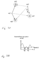
- Fig. 1 shows an exemplary communication scenario consisting of two base stations BS Tx and BS Rx and two mobile stations MS Rx and MS Tx .
- BS Tx is transmitting to MS Rx on sub-channels #n and #m.
- MS Rx sends out a busy-signal on a mini-slot at the same channel (because of TDD).
- MS Rx transmits the busy-signal on sub-channels #n and #m (indicated by co-centric circles).
- MS Tx wants to start communicating to BS Rx . Before MS Tx starts transmitting, it listens to the busy-signals on all sub-channels.
- MS Tx It compares the received power with a pre-defined threshold (for convenience the received busy-signal is drawn as a smooth line - in practice the received signal per sub-channel might vary more abruptly because of multiple transmission sources).
- MS Tx starts transmission on those sub-channels at which the busy-signal is received below the threshold.
- MS Tx is allowed to re-use sub-channel #n.
- it can transmit on sub-channel #p which might be used on some other co-existing link.
- the potential new transmitter can exactly determine the level of interference it would cause to other links prior to transmission. This is seen as an important advantage.
- Fig. 2 shows another exemplary, simple scenario consisting of two base stations and three mobile stations in order to illustrate the co-channel interference (CCI) problem in cellular networks with frequency re-use of one and the busy-tone approach.
- the busy-signal is also referred to as busy-tone or busy-burst.
- BS Tx or MS Tx a transmitting base station or mobile station
- BS Rx or MS Rx a receiving base station or mobile station
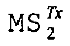
- the mobile station MS 2 Tx transmits to the base station BS 2 Rx .
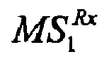
- MS 2 Tx causes CCI to MS 1 Rx and MS 3 Rx
- the base station BS 1 Tx causes CCI to the base station BS 2 Rx .
- the level of CCI in a network with full frequency reuse significantly reduces spectral efficiency.
- a fixed frequency allocation scheme too, prohibits high spectral efficiency.
- the busy-tone concept has been developed to solve this problem in a self-organising fashion. A single carrier based air-interface with TDMA (Time Division Multiple Access) is assumed. Each time slot (TS) is followed by a mini-slot which is used for busy-tone signalling.
- TDMA Time Division Multiple Access
- a receiver Upon successful reception of a data packet, a receiver broadcasts a busy-signal on this mini-slot. Each potential transmitter in the vicinity of this receiver first listens to the mini-slot, and if the received signal power at the mini-slot is above the threshold, the new potential transmitter refrains from transmission as it would cause too high interference to the co-existing transmission. Clearly, this is only possible because of the use of TDD.
- Fig. 3 shows the inventive concept of the dynamic sub-channel allocation mechanism for a multi-user OFDM network based on the scenario already described in Fig. 2.
- the new dynamic sub-channel allocation method is a new dynamic, scenario dependent and self-organizing channel allocation method especially tailored for an OFDM/TDD based air-interface which exploits the busy-tone approach.
- this protocol is that the transmitter, before sending data, first selects sub-channels which do not cause significant CCI to other users in the network. This is accomplished by sensing the channel at a special time-multiplexed channel referred to as busy-channel, e.g. one particular OFDM symbol, which is used for busy-tone transmission. A receiver upon 'correct' data reception immediately transmits a signal on each of the used sub-channels on the busy-channel to reserve these particular sub-channels for further transmission. Any potential new transmitter will select sub-channels for its transmission based on the received power on the sub-channels of the busy-channel. If the received power on a particular sub-channel is above a certain threshold, this would mean that a co-existing transmission will be greatly interfered.
- busy-channel e.g. one particular OFDM symbol
- MS 2 Tx can transmit on sub-channels #p and #q given the depicted received busy-signal from MS 1 Rx and MS 3 Rx .
- the CTF Channel Transfer Function
- Fig. 4 a typical two-dimensional frequency response or channel transfer function of a time- and frequency-selective radio frequency channel is depicted.
- the frequency selectivity of the channel governs the sub-channel selection.
- the time variability requires a continuous sub-channel selection process, both of which are catered for in this invention.
- the inventive method addresses two problems: first, an approach to decide which time/frequency resources of MS 2 Tx , for example, have negligible interference to the other mobile stations and base stations, and second the assignment of time/frequency resources of the selected sub-channels, for example selected by MS 2 Tx , and to decide which of the selected sub-channels are not subject to interference at, for example the desired receiver BS 2 Rx . Due to TDD and its inherent channel reciprocity, the received busy-tone from the mobile stations MS 1 Rx and MS 3 Rx to MS 2 Tx indicate at the same time the potential interference the mobile station MS 2 Tx would cause to the mobile stations MS 1 Rx and MS 3 Rx .
- MS 2 Tx will only transmit on sub-channels which cause negligible interference to the other two mobile stations MS 1 Rx and MS 3 Rx .
- the decision, whether a transmission on a certain sub-channel to a certain point of time is considered causing negligible interference, is based on a threshold decision, for example the signal or signal power has to be equal or below a certain power threshold.
- the entire procedure can be sub-divided into two phases, (a) the link initialisation phase and (b) the continuous and dynamic sub-channel adaptation phase.
- the initialization phase a new communication link is established and a number of sub-channels have to be selected.
- the adaptation phase the target receiver has received data, but channel and interference variations make it necessary to select new sub-channels for transmission, or release used sub-channels.
- the link initialization phase is explained in more detail. It is assumed that the m-th BS wants to set-up a link to the k-th MS in the (i-2)-th MAC frame, i.e. the inter-arrival is at a random time position in the (i-2)-th MAC frame, and it is, therefore, not guaranteed that the busy-channel can be heard during this MAC frame period. Hence, the BS has to defer its transmission until the next MAC frame, i.e. the (i-1)-th MAC frame where it gets the first proper chance to listen to the busy-channel. The received busy-signal is compared against a given threshold as explained before.
- the received busy-signals at this point of time can only result from non-intended MSs or BSs (potential entities which might suffer interference if transmission started) as the target receiver has not, as yet, received any data, i.e. a busy-signal could not have been transmitted.
- the m-th BS commences data transmission to the k-th MS on these sub-channels.
- the k-th MS determines the SINR (signal-to-interference plus noise) on each of these sub-channels. Based on the required QoS (Quality of Service) for that particular service it will decide whether to 'reserve' the respective sub-channel, or whether to 'release' it.
- QoS Quality of Service
- a l , i - 1 k , m ⁇ 1 if B ⁇ l , i - 1 m 2 ⁇ I thr 0 otherwise , where B ⁇ l , i - 1 m is the received busy-signal at the m-th BS on the 1-th sub-channel in the (i-1)-th MAC frame.
- the threshold which is a measure for the interference that this transmission would cause to other co-existing transmissions, is denoted as I thr .
- the decision for the value of a l , i - 1 k , m is made by the transmitter to mitigate CCI, whereas the decision for the value of b l , i - 1 k , m is made by the receiver to release those sub-channels which do not fulfil the SINR target.
- the received busy-signal powers are composed of the signal powers of the intended user, the k-th MS, and the busy-signal powers of all other entities which are potentially subject to interference. This means that the busy-signal power for the sub-channels used is different from that in the (i-1)-th MAC frame in which the communication between the m-th BS and the k-th MS was initiated, and in which the intended receiver, the k-th MS, has not transmitted a busy-signal.
- B l , i k and B ⁇ l , i m are the transmitted and the received busy-signal on the 1-th sub-channel and at the i-th MAC frame between the k-th MS and the m-th BS, respectively.
- the denotation H l , i k , m represents the CTF coefficient for the 1-th sub-channel and the i-th MAC frame of the transmission between the m-th BS and the k-th MS, i.e. the desired link.
- the symbol H l , i k ⁇ , m is the CTF coefficient between the k'-th terminal (it could be an MS or BS of a co-existing link) and the m-th BS.
- the condition a l , i - 1 k , m ⁇ B ⁇ l , i m 2 ⁇ I thr means the sub-channel 1 has not been selected in the (i-1)-th MAC frame and the received busy-signal on this sub-channel at the busy-tone slot of the i-th MAC frame is lower than the given threshold. If this condition is fulfilled, then this sub-channel is selected for data transmission in the next MAC frame.
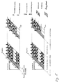
- Fig. 5 shows an exemplary embodiment of the MAC frame structure which accounts for downlink and uplink transmission.
- the upper part of Fig. 5 depicts transmission and reception of signals from the BS point of view.
- the lower part depicts transmission and reception from the MS point of view.
- the structure of an uplink sub-frame is similar to the structure of a downlink sub-frame. Due to this similarity and to ensure greater clarity the uplink sub-frame is not explained further at this point.
- Each sub-frame includes a busy-channel (one OFDM symbol) for busy-tone signalling.
- the MAC frame duration is selected such that the channel does not change significantly.
- Fig. 5 shows an exemplary communication between a base station and a mobile station, wherein the base station wants to send data to the mobile station.
- the base station wants to set up the communication link to the mobile station in the (i - 2)-th MAC frame. Therefore, at the (i - 1)-th MAC frame, it first listens to the busy-signal on all sub-channels. In the example, it is assumed that the received busy-signal power of the first, third and fourth sub-channels falls below the given threshold which are subsequently selected for data transmission. It is further assumed that the SINR on the first sub-channel in the downlink at the intended MS is unacceptable.
- the MS does not broadcast the busy-signal on the first sub-channel in the next, i-th, MAC frame, i.e. the MS transmits the busy-signal only on the third and fourth sub-channels. Because of channel variations on the interference link, the busy-signal on the second sub-channel at the i-th MAC frame is received below the threshold. Therefore, the second sub-channel is selected for downlink transmission in the ith MAC frame. Note that the first sub-channel is released as the required SINR at the intended MS was not achieved in the i-1-th MAC frame.
- the transmitter or the transmitting base station analyses the various busy-tones and sends based on the analysis the data in the same MAC frame.
- Alternative concepts with delays, for example between the analysis of the busy-tones and the first sending of data are possible, but short or no delays are preferred due to the time dependence of the general transfer function and interference by other transmitters.
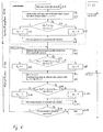
- Fig. 6 shows a flow-chart of a preferred embodiment of the inventive method.
- Tx for transmitter and Rx for receiver performing the described task are shown.
- frame indexes (i - 2), (i - 1) and (i) have been added for an easier comparison to the afore mentioned descriptions of the phases of "initialization” and "dynamic sub-channel adaptation".
- Fig. 6 The following descriptive text to Fig. 6 in contrast there to, explains the method including the steps of incrementing "i" as shown in Fig. 6.
- the initialization phase 610 and the adaptation phase or continuous adaptation of sub-channels 630 is shown in Fig. 6.
- a set of sub-channels will be selected by comparing the square amplitude of the received busy-signal
- the user indices k and m are neglected for simplicity.
- the corresponding value of the channel assignment symbol a l,i will be set (step S4).
- This comparison is executed for ⁇ l ⁇ C, where C is the set of all sub-channels of the system. Subsequently, data symbols are transmitted on the selected sub-channels (step S5).
- an indication may be sent to the receiver, for example the general assignment symbol a l,i to indicate for which receiver the data is addressed to, and to indicate from which transmitter the data is transmitted from. Based on this information each receiver knows whether the data on a particular sub-channel is addressed to the particular receiver .
- the initialization phase 610 for the communication between the transmitter and the receiver ends with the first transmission of data by the transmitter.
- the adaptation phase 630 of the communication link between the transmitter and the receiver starts with the first interference power estimation at the receiver on all selected sub-carriers (step S6), and starting from there on is continuously performed by the receiver and the transmitter until the link is terminated or the communication is terminated (step S14).
- the receiver estimates the SINR on the selected sub-channels (step S6).
- the transmitter continuously checks the condition of eqn. (5) to adapt the set of used sub-channels for the respective link (steps S10 -S12).
- Step S13 If the communication on the particular link should be continued in the next MAC frame (step S13), Steps 2-5 are repeated, if not, the communication is terminated (step S14).
- the transmitter also transmits an information to the receiver if the transmitter wants to send more data in general or more data particularly over this selected sub-channel to the transmitter in the following frame. In the case where the transmitter signals that there is no further data to be sent over the selected sub-channel in the next frame, the receiver will not send a busy-signal even if the quality or SINR was greater than the predetermined fourth threshold.
- Fig. 7A shows an exemplary received two-dimensional busy-signal H(f,t) at for example mobile station MS 2 Tx of Fig. 3 and clearly shows that all links are subject to general variations in time and frequency.
- Fig. 7B shows the received busy-tone at MS 2 Tx as shown in Fig. 7A with an exemplary threshold value depicted, the black plane. Based on the received busy-tone MS 2 Tx would only chose those sub-channels for a transmission which are below the black plane.
- the receiver or receiving base station BS 2 Rx transmits a busy-tone after successful reception of the data sent by MS 2 Tx , wherein the receiving base station BS 2 Rx transmits only busy-tones on sub-channels, which are claimed or allocated by the transmitting mobile station MS 2 Tx and are not subject to interference at the receiving base station BS 2 Rx . Based on these pre-requisites, adaptive coding and modulation methods can now be applied.
- FIG. 7C An exemplary busy-tone from the receiving base station BS 2 Rx to the transmitting mobile station MS 2 Tx , H' (f,t), is shown in Fig. 7C.
- the received busy-tone H' (f,t) shows signal power values above a threshold, ⁇ req ., for frequencies for which the signal power values in the received busy-tone H(f,t) were below the threshold, I thr , as shown in Fig. 7B.
- ⁇ req for frequencies for which the signal power values in the received busy-tone H(f,t) were below the threshold, I thr .
- Fig. 8A shows an exemplary simulation setup to compare the inventive method being a decentralized dynamic sub-channel allocation method, and a possible centralized non-dynamic sub-channel allocation method.
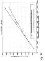
- the graphs of both methods show an almost linear increase of the average throughput with the average offered load, nevertheless Fig. 8B shows already that the inventive method outperforms the centralized non-dynamic sub-channel allocation method.
- the inventive method is applicable for any combination of transmitting and receiving devices, for example a transmitting mobile station and a receiving mobile station, a transmitting mobile station and a receiving base station, a transmitting base station and a receiving base station and a transmitting base station and a receiving base station.
- the inventive method provides a communication method for, as described before, cellular networks, ad hoc networks and multi-hop networks due to its decentralized, self-organizing dynamic sub-channel allocation between all nodes within a communication network based on the inventive communication method.
- an inventive method can use a same threshold value for all decisions or can be implemented to comprise different threshold values for the different situations a decision has to be made, for example a first threshold in case the transmitter has already used the sub-channel for data communication, a second or third threshold in case the sub-channel has not been used for a data transmission in a preceding frame, for example during initialization or later during the adaptation phase (second or third threshold for the busy-signal evaluation).
- the absolute power values are given by the regulator. Therefore, the absolute power values not only of the payload data but also of the busy-signal may be specified by the regulator.
- Exemplary power values of the busy-signal are in a range of -40 dBm to 50 dBm at the point of transmission and the first, second and third predetermined thresholds of a power value of the busy-signal in a range of -40 dBm and -150 dBm.
- the power values of the busy-signal can also be expressed relative to the power level of the payload data, e.g. that the busy signal is between 20dB stronger and 20dB weaker with respect to the payload data.
- the radio frequency channel in broadband wireless access the radio frequency channel is generally frequency selective.
- the channel is slowly fading, for example due to low Doppler spread. This applies to the desired as well as the interference link in a multi-cell environment. While methods such as water filling and bit loading work well in single link and single user transmission, no effective solutions exist which also consider the frequency selectivity on the interference link in a multi-user and multi-cell deployment.
- the invention provides a new dynamic sub-channel allocation protocol, which involves the physical layer as well as the MAC layer for, for example, an OFDM-TDD based cellular system or air-interface.
- the inventive method or related protocols exploit the channel reciprocity of TDD and the busy-tone signalling on, for example, time-multiplexed sub-channels in order to establish a two-fold mechanism; first interference avoidance and second link adaptation.
- first interference avoidance and second link adaptation.
- the protocol ensures that existing transmissions are protected. This means that any new transmitter is aware of the level of interference it would cause to an existing transmission, and is able to make appropriate decisions, i.e. (a) refrain from using a particular sub-channel because it would cause too much interference to a co-existing link, or (b) use a particular sub-channel because interference caused to other links is negligible. Thereby, a dynamic, interference-sensitive and self-organising FDMA mechanism in OFDM is achieved. This means, the transmitter selects sub-channels solely based on interference which may be caused elsewhere.
- the inventive method dynamically manages interference utilizing busy burst signalling, achieves high spectral efficiency in a multi-user, multi-cell environment, does not require a central radio resource controller for the network, thus being applicable for cellular, ad hoc and multi-hop networks, and finally results in low signalling overhead.
- the inventive methods can be implemented in hardware or in software.
- the implementation can be performed using a digital storage medium, in particular a disc, DVD or a CD having electronically readable control signals stored thereon, which cooperate with a programmable computer system such that the inventive methods are performed.
- the present invention is, therefore, the computer program product with a program code stored on a machine readable carrier, the program code being operative for performing the inventive methods when the computer program product runs on a computer.
- the inventive methods are therefore, a computer program having a program code for performing at least one of the inventive methods when the computer program runs on a computer.
Landscapes
- Engineering & Computer Science (AREA)
- Quality & Reliability (AREA)
- Computer Networks & Wireless Communication (AREA)
- Signal Processing (AREA)
- Mobile Radio Communication Systems (AREA)
Abstract
Description
- The present invention is in the field of dynamic sub-channel allocation and medium access control (MAC), for example for multi user access in cellular, ad hoc and multi-hop based networks.
- Unlike spread spectrum techniques OFDM (Orthogonal Frequency Division Multiplexing) does not have an in-built interference resistance mechanism which would enable OFDM to be used in multiple cell environments such that a full frequency or sub-channel reuse would be possible. Therefore, the issue of an intelligent sub-channel reuse scheme in order to effectively combat co-channel interference (CCI) is an open problem. In addition, in ad hoc or multi-hop networks the lack of central radio resource management or sub-channel management control adds a further complication.
- Several approaches exist which aim at addressing the problem stated above.
- First, the use of the cellular concept in which the entire radio frequency band is subdivided into sub-bands each of which is used in different cells according to a particular frequency reuse pattern. For broadband wireless access, which relies on large bandwidth, this solution which originally is tailored for low rate circuit switched services is an infeasible or at least a highly inefficient solution.
- Second, the use of sub-channel (frequency) hopping, but this lacks the systematic exploitation of available resources. As a consequence this approach only works well in low load situations. The main advantage is the reduction in complexity as only little coordination (signalling overhead) is required.
- Third, the use of channel sensing or random MAC protocols such as CSMA-CA (Carrier Sensing Multiple Access - Collision Avoidance). Most of the state-of-the-art protocols result in poor spectrum efficiency, and/or in a large signalling overhead.
- P. Omiyi and H. Haas showed in "Improving Time-Slot Allocation in 4th Generation OFDM/TDMA TDD Radio Access Networks with Innovative Channel-Sensing" in Proceedings of the International Conference on Communications ICC '04, vol. 6, Paris, France: IEEE, June 20-24 2004, pp. 3133 - 3137, in the following [1], that a new MAC protocol tailored for a TDD based air-interface using busy-tone in combination with mini-slots can achieve high spectrum efficiency in single carrier transmission.
- The patent application
PCT/EP 2004/011840 WO 2005 041494 orEP 1 526 685 - It is the object of the present invention to provide an improved concept for a dynamic sub-channel allocation for broadband wireless access systems.
- This object is achieved by a method for dynamic sub-channel allocation according to
claim 1, a computer program according to claim 11, a transmitter according to claim 12, a receiver according toclaim 13 and a system for dynamic sub-channel allocation according to claim 14. - The present invention provides a method for a dynamic sub-channel allocation for communication between a transmitter and a receiver in a communication system comprising a communication channel having a plurality of sub-channels, the method comprising: receiving at the transmitter from the plurality of sub-channels respective busy-signals, each busy-signal being indicative of a communication on the respective sub-channel in the communication system, and selecting one or more sub-channels for a communication between the transmitter and the receiver by allocating a sub-channel for the communication, in case the busy-signal received from the sub-channel is equal to or greater than a first predetermined threshold and the sub-channel was used for a communication between the transmitter and the receiver in a preceding communication interval, or the busy-signal received from the sub-channel is equal to or less than a second predetermined threshold and the sub-channel was not used for a communication between the transmitter and the receiver in a preceding communication interval.
- Furthermore, the present invention provides a computer program having a program code for performing the inventive method, when the program runs on a computer.
- Furthermore, the present invention provides a transmitter for dynamic sub-channel allocation for communication with a receiver in a communication system comprising a communication channel having a plurality of sub-channels, the transmitter comprising: a means for receiving from the plurality of sub-channels respective busy-signals, each busy-signal being indicative of a communication on the respective sub-channel in the communication system, and a controller for selecting one or more sub-channels for a communication between the transmitter and the receiver by allocating a sub-channel for the communication, in case the busy-signal received from the sub-channel is equal to or greater than a first predetermined threshold and the sub-channel was used for a communication between the transmitter and the receiver in a preceding communication interval, or the busy-signal received from the sub-channel is equal to or less than a second predetermined threshold and the sub-channel was not used for a communication between the transmitter and the receiver in a preceding communication interval.
- Furthermore, the present invention provides a receiver for communication with a transmitter operative for dynamic sub-channel allocation in a communication system comprising a communication channel having a plurality of sub-channels, the receiver comprising: a means for receiving signals over a sub-channel allocated for communication by the transmitter, a means for generating a busy-signal on the sub-channel allocated for communication by the transmitter in case the signals received over this allocated sub-channel are equal to or greater than a predetermined threshold.
- Also the present invention provides a system for communication comprising the inventive transmitter and the inventive receiver.
- The present invention is based on the finding that an improvement of the dynamic sub-channel allocation can be achieved by dividing the communication channel into a plurality of sub-channels. Smaller sub-channels are less frequency selective and their channel transfer function can be much better approximated or modelled. Therefore, adaptive coding and modulation concepts can now be applied.
- This invention, therefore, provides a novel protocol for a dynamic self-organising sub-channel selection mechanism in an OFDM-TDD (TDD = Time Division Duplexing) based network which does not require central control.
- Measuring the interference of a complete channel versus measuring the interference of sub-channels, has a two-fold disadvantage. First, based on the prior art approach, a frequency range for which the distortion would be negligible can not be used if the distortion of the rest of the channel or the majority of the channel can not be neglected. Valuable frequency bands or sub-channels remain unnecessarily unused. Second, certain frequency ranges might show a high distortion, whereas the rest of the frequencies of the channel show a negligible distortion. Using the channel based on "majority decision" might cause unnecessary outages and retransmissions due to the high distortion within the afore mentioned frequency band.
- The inventive method provides more accurate distortion decisions and finally achieves improved spectral efficiency in a multi-user, multi-cell environment compared to the prior art.
- In a preferred embodiment of the invention, an OFDM-TDD based air-interface is used. The inventive method uses a dynamic sub-channel selection algorithm which involves a physical as well as a MAC (Medium Access Control) layer by exploiting channel reciprocity in TDD, and uses furthermore busy-tone signalling on time-multiplexed sub-channels.
- Channel reciprocity of TDD means that a potential interference from, for example, a first mobile station MSTx transmitting data to a second mobile station MSRx receiving data is identical to the interference the second mobile station MSRx transmitting data would impose on the first mobile station MSTx receiving data provided that the transmit powers are the same.
- The inventive method enables a frequency re-use of one, or in other words a frequency re-use of 100%, and basically results in a dynamic FDMA (Frequency Division Multiple Access) component in an OFDM-based air-interface. Clusters of sub carriers, or chunks are assigned for data transmission between a transmitter and a receiver only if these sub-channels cause negligible interference to potential victim receivers, i.e. only if the interference link is deeply faded or attenuated. In order to detect deep fades of the channel, channel sensing by means of busy-tone signalling is used. Since in TDD mode transmission and reception is on the same radio frequency channel, a short signal send out, for example, by the receiver of the intended mobile station (MS) can be used by a dislocated potential interfering transmitter to determine the interference power it would cause to that receiver given that the transmit power of the busy-signal is a priori known by the potential interfering transmitter. This particular mechanism is exploited in this invention. Additionally, provision is made for an adaptive sub-channel assignment when the channel is slowly time varying.
- The inventive method, therefore, offers the following advantages: high spectral efficiency in a multi-user, multi-cell environment for broadband wireless access, no requirement for a central radio resource controller for the network, therefore, the inventive technique is applicable for cellular, ad hoc or multi-hop networks, and exhibits a low signalling overhead.
- Preferred embodiments of the present invention are described in detail with respect to the following Figures, in which:
- Fig. 1A
- shows a scenario for an exemplary communication network including two base stations BSTx, BSRx and two mobile stations MSRx, MSTx;
- Fig. 1B
- shows an exemplary received busy-tone at potential transmitter MSTx with two deeply faded sub-channels #n and #p;
- Fig. 2
- shows an exemplary scenario consisting of two base stations and three mobile stations illustrating the co-channel interference problem in cellular networks with a frequency re-use of one;
- Fig. 3A
- shows the concept of the inventive dynamic channel allocation mechanism for an OFDM/TDD network with 100% frequency re-use based on the scenario of Fig. 2;
- Fig. 3B
- shows the received busy tone power at mobile station

- Fig. 4
- shows a typical two-dimensional frequency response of a radio frequency channel;
- Fig. 5
- shows a preferred embodiment of the inventive MAC frame structure showing the down link and the uplink transmission;
- Fig. 6
- shows a flow-chart of a preferred embodiment of the inventive method;
- Fig. 7A
- shows an exemplary two-dimensional busy-signal during an initialisation phase;
- Fig. 7B
- shows the exemplary two-dimensional two-dimensional busy-signal of Fig. 7A and a given threshold value;
- Fig. 7C
- shows an exemplary two-dimensional busy-tone response to a first transmission based on Figs. 7A-B during a channel adaptation phase;
- Fig. 8A
- shows a simulation setup for comparing the performance of the inventive decentralized dynamic sub-channel allocation method and a centralized nondynamic sub-channel allocation method;
- Fig. 8B
- shows the average throughout over the average offered load for the simulation setup of Fig. 8A with a threshold ITHR = -80 dBm;
- Fig. 8C
- shows the average throughput over the average offered load for the simulation setup of Fig. 8A with a threshold of ITHR = -100 dBm.
- Fig. 1 shows an exemplary communication scenario consisting of two base stations BSTx and BSRx and two mobile stations MSRx and MSTx. BSTx is transmitting to MSRx on sub-channels #n and #m. On successful reception MSRx sends out a busy-signal on a mini-slot at the same channel (because of TDD). Specifically, MSRx transmits the busy-signal on sub-channels #n and #m (indicated by co-centric circles). At the same time, MSTx wants to start communicating to BSRx. Before MSTx starts transmitting, it listens to the busy-signals on all sub-channels. It compares the received power with a pre-defined threshold (for convenience the received busy-signal is drawn as a smooth line - in practice the received signal per sub-channel might vary more abruptly because of multiple transmission sources). MSTx starts transmission on those sub-channels at which the busy-signal is received below the threshold. In the example, MSTx is allowed to re-use sub-channel #n. Similarly, it can transmit on sub-channel #p which might be used on some other co-existing link. As the transmission and reception is on the same radio frequency carrier, the potential new transmitter can exactly determine the level of interference it would cause to other links prior to transmission. This is seen as an important advantage.
- Fig. 2 shows another exemplary, simple scenario consisting of two base stations and three mobile stations in order to illustrate the co-channel interference (CCI) problem in cellular networks with frequency re-use of one and the busy-tone approach. The busy-signal is also referred to as busy-tone or busy-burst.
- In the following a transmitting base station (BS) or mobile station (MS) are denoted as BSTx or MSTx and a receiving base station or mobile station are denoted as BSRx or MSRx.
- In the example, the
mobile station 
base station 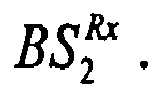
scenario 


base station 
base station 
- Fig. 3 shows the inventive concept of the dynamic sub-channel allocation mechanism for a multi-user OFDM network based on the scenario already described in Fig. 2. The new dynamic sub-channel allocation method is a new dynamic, scenario dependent and self-organizing channel allocation method especially tailored for an OFDM/TDD based air-interface which exploits the busy-tone approach.
- The nature of this protocol is that the transmitter, before sending data, first selects sub-channels which do not cause significant CCI to other users in the network. This is accomplished by sensing the channel at a special time-multiplexed channel referred to as busy-channel, e.g. one particular OFDM symbol, which is used for busy-tone transmission. A receiver upon 'correct' data reception immediately transmits a signal on each of the used sub-channels on the busy-channel to reserve these particular sub-channels for further transmission. Any potential new transmitter will select sub-channels for its transmission based on the received power on the sub-channels of the busy-channel. If the received power on a particular sub-channel is above a certain threshold, this would mean that a co-existing transmission will be greatly interfered. Conversely, if the received power is below that threshold, the channel attenuation is high enough such that usage of this sub-channel would only yield negligible interference to the co-existing transmission. In Fig. 3, for example,


- Due to the inherent nature of the wireless channel, the CTF (Channel Transfer Function) of the individual channels may change over time which resembles the initial sub-channel selections sub-optimum. In Fig. 4, a typical two-dimensional frequency response or channel transfer function of a time- and frequency-selective radio frequency channel is depicted. The frequency selectivity of the channel governs the sub-channel selection. The time variability requires a continuous sub-channel selection process, both of which are catered for in this invention.
- The inventive method addresses two problems: first, an approach to decide which time/frequency resources of


receiver 
mobile stations 

mobile station 
mobile stations 

- Based on the inventive method,

mobile stations 

- The entire procedure can be sub-divided into two phases, (a) the link initialisation phase and (b) the continuous and dynamic sub-channel adaptation phase. During the initialization phase a new communication link is established and a number of sub-channels have to be selected. In the adaptation phase, the target receiver has received data, but channel and interference variations make it necessary to select new sub-channels for transmission, or release used sub-channels.
- In the following the link initialization phase is explained in more detail. It is assumed that the m-th BS wants to set-up a link to the k-th MS in the (i-2)-th MAC frame, i.e. the inter-arrival is at a random time position in the (i-2)-th MAC frame, and it is, therefore, not guaranteed that the busy-channel can be heard during this MAC frame period. Hence, the BS has to defer its transmission until the next MAC frame, i.e. the (i-1)-th MAC frame where it gets the first proper chance to listen to the busy-channel. The received busy-signal is compared against a given threshold as explained before. Notice that the received busy-signals at this point of time can only result from non-intended MSs or BSs (potential entities which might suffer interference if transmission started) as the target receiver has not, as yet, received any data, i.e. a busy-signal could not have been transmitted. This means that the m-th BS commences data transmission to the k-th MS on these sub-channels. The k-th MS determines the SINR (signal-to-interference plus noise) on each of these sub-channels. Based on the required QoS (Quality of Service) for that particular service it will decide whether to 'reserve' the respective sub-channel, or whether to 'release' it. In the latter, it would not transmit the busy-signal on that corresponding sub-channel, whereas in the former it would reserve the respective sub-channel by 'protecting' it using the busy-signal. Clearly, this protection is only feasible because of the use of TDD. Note that the SINR at a particular sub-channel might be small because either the channel of this sub-channel on the desired link is deeply faded, or because there is high interference resulting from another transmission. Therefore, the busy-signal is not broadcast on this sub-channel in the next, i-th, MAC frame.
- In order to mathematically model this behaviour,

sub-channel 1 at MAC frame (i-1) is assigned for the link between m-th BS and k-th user, then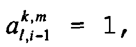


where


- Note that the decision for the value of


- In the following the phase of the dynamic sub-channel allocation is explained in more detail. For any MAC frame greater than or equal to i, the received busy-signal powers are composed of the signal powers of the intended user, the k-th MS, and the busy-signal powers of all other entities which are potentially subject to interference. This means that the busy-signal power for the sub-channels used is different from that in the (i-1)-th MAC frame in which the communication between the m-th BS and the k-th MS was initiated, and in which the intended receiver, the k-th MS, has not transmitted a busy-signal.
- The received busy-signal in the downlink sub-frame of the i-th MAC frame can be written as follows

where


- The condition for the sub-channel assignment on the desired link between the m-th BS and the k-th MS for the i-th, and any MAC frame greater than i, is given as follows,

where α̅ is the logic complement of a. In eqn. (5), the condition
sub-channel 1 has not been selected in the (i-1)-th MAC frame and the received busy-signal on this sub-channel at the busy-tone slot of the i-th MAC frame is lower than the given threshold. If this condition is fulfilled, then this sub-channel is selected for data transmission in the next MAC frame. The condition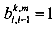
sub-channel 1 has been selected in the previous MAC frame and the required SINR is maintained. In this case, thesub-channel 1 is continued to be selected for this link. - Fig. 5 shows an exemplary embodiment of the MAC frame structure which accounts for downlink and uplink transmission. The upper part of Fig. 5 depicts transmission and reception of signals from the BS point of view. Similarly, the lower part depicts transmission and reception from the MS point of view. The structure of an uplink sub-frame is similar to the structure of a downlink sub-frame. Due to this similarity and to ensure greater clarity the uplink sub-frame is not explained further at this point. Each sub-frame includes a busy-channel (one OFDM symbol) for busy-tone signalling. The MAC frame duration is selected such that the channel does not change significantly.
- Fig. 5 shows an exemplary communication between a base station and a mobile station, wherein the base station wants to send data to the mobile station. Likewise to the prior explanation about the two phases "link initialization" and "dynamic sub-channel adaptation", the base station wants to set up the communication link to the mobile station in the (i - 2)-th MAC frame. Therefore, at the (i - 1)-th MAC frame, it first listens to the busy-signal on all sub-channels. In the example, it is assumed that the received busy-signal power of the first, third and fourth sub-channels falls below the given threshold which are subsequently selected for data transmission. It is further assumed that the SINR on the first sub-channel in the downlink at the intended MS is unacceptable. Therefore, the MS does not broadcast the busy-signal on the first sub-channel in the next, i-th, MAC frame, i.e. the MS transmits the busy-signal only on the third and fourth sub-channels. Because of channel variations on the interference link, the busy-signal on the second sub-channel at the i-th MAC frame is received below the threshold. Therefore, the second sub-channel is selected for downlink transmission in the ith MAC frame. Note that the first sub-channel is released as the required SINR at the intended MS was not achieved in the i-1-th MAC frame.
- In Fig. 5 the transmitter or the transmitting base station analyses the various busy-tones and sends based on the analysis the data in the same MAC frame. Alternative concepts with delays, for example between the analysis of the busy-tones and the first sending of data are possible, but short or no delays are preferred due to the time dependence of the general transfer function and interference by other transmitters.
- Fig. 6 shows a flow-chart of a preferred embodiment of the inventive method. In Fig. 6 additionally to the flow-chart the respective entities, Tx for transmitter and Rx for receiver, performing the described task are shown. On the right hand side of Fig. 6 frame indexes (i - 2), (i - 1) and (i) have been added for an easier comparison to the afore mentioned descriptions of the phases of "initialization" and "dynamic sub-channel adaptation".
- The following descriptive text to Fig. 6 in contrast there to, explains the method including the steps of incrementing "i" as shown in Fig. 6. The initialization phase 610 and the adaptation phase or continuous adaptation of
sub-channels 630 is shown in Fig. 6. At initialization 610, it is assumed that there is a new arrival in the network in the MAC frame i (steps S1, S2). A set of sub-channels will be selected by comparing the square amplitude of the received busy-signal |B̂l,i |2 with the threshold (step S3). In Fig. 6, the user indices k and m are neglected for simplicity. Depending on the comparison result, the corresponding value of the channel assignment symbol al,i will be set (step S4). This comparison is executed for ∀l∈C, where C is the set of all sub-channels of the system. Subsequently, data symbols are transmitted on the selected sub-channels (step S5). - Together with the data symbols an indication may be sent to the receiver, for example the general assignment symbol al,i to indicate for which receiver the data is addressed to, and to indicate from which transmitter the data is transmitted from. Based on this information each receiver knows whether the data on a particular sub-channel is addressed to the particular receiver .
- The initialization phase 610 for the communication between the transmitter and the receiver ends with the first transmission of data by the transmitter.
- The
adaptation phase 630 of the communication link between the transmitter and the receiver starts with the first interference power estimation at the receiver on all selected sub-carriers (step S6), and starting from there on is continuously performed by the receiver and the transmitter until the link is terminated or the communication is terminated (step S14). - In addition to data equalization and detection, the receiver estimates the SINR on the selected sub-channels (step S6). A selected sub-channel is continued to be used for the next MAC frame, i.e. bl,i = 1, if the estimated SINRon this sub-channel is greater than the required value γmin. which is denoted γreq. in (2) and which actually depends on the QoS constraint (steps S7, S8).

- The MAC frame index points to the next MAC frame i := i+1. The busy-signal is transmitted by the receiver on the selected sub-channels with bl,i = 1 using the busy-channel (step S9).
- On the busy-channel, the transmitter continuously checks the condition of eqn. (5) to adapt the set of used sub-channels for the respective link (steps S10 -S12).
- If the communication on the particular link should be continued in the next MAC frame (step S13), Steps 2-5 are repeated, if not, the communication is terminated (step S14).
- In a preferred embodiment of the invention, the transmitter also transmits an information to the receiver if the transmitter wants to send more data in general or more data particularly over this selected sub-channel to the transmitter in the following frame. In the case where the transmitter signals that there is no further data to be sent over the selected sub-channel in the next frame, the receiver will not send a busy-signal even if the quality or SINR was greater than the predetermined fourth threshold.
- Fig. 7A shows an exemplary received two-dimensional busy-signal H(f,t) at for example
mobile station 
- Fig. 7B shows the received busy-tone at

tone 
base station 

base station 
mobile station 
base station 
- An exemplary busy-tone from the receiving
base station 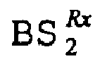
mobile station 
- Fig. 8A shows an exemplary simulation setup to compare the inventive method being a decentralized dynamic sub-channel allocation method, and a possible centralized non-dynamic sub-channel allocation method. Fig. 8 shows an OFDM/TDD setup with a system band width B = 20 MHz and FFT length NFFT = 256, comprising a channel model based on a maximum Doppler frequency fD,max = 500 Hz and a maximum channel delay of Tmax = 6.4 µs, and being based on a cellular system model with a cell radius of 500 meters and uniformly distributed mobile stations.
- Fig. 8B shows an average throughput of the system over an average offered load for both afore mentioned methods at a threshold Ithr = -80 dBm. The graphs of both methods show an almost linear increase of the average throughput with the average offered load, nevertheless Fig. 8B shows already that the inventive method outperforms the centralized non-dynamic sub-channel allocation method.
- Fig. 8C shows again the average throughput versus the average offered load for both afore mentioned methods, but now with a threshold of Ithr = -100 dBm. At this threshold level the inventive method clearly outperforms the centralized non-dynamic sub-channel allocation method. The average throughput for the inventive method still increases linearly with the average offered load whereas the average throughput of the centralized non-dynamics sub-channel allocation method does not exceed 1.000 bits per OFDM symbol.
- It should be noted that the inventive method is applicable for any combination of transmitting and receiving devices, for example a transmitting mobile station and a receiving mobile station, a transmitting mobile station and a receiving base station, a transmitting base station and a receiving base station and a transmitting base station and a receiving base station. Thus, the inventive method provides a communication method for, as described before, cellular networks, ad hoc networks and multi-hop networks due to its decentralized, self-organizing dynamic sub-channel allocation between all nodes within a communication network based on the inventive communication method.
- Furthermore, it should be noted that an inventive method can use a same threshold value for all decisions or can be implemented to comprise different threshold values for the different situations a decision has to be made, for example a first threshold in case the transmitter has already used the sub-channel for data communication, a second or third threshold in case the sub-channel has not been used for a data transmission in a preceding frame, for example during initialization or later during the adaptation phase (second or third threshold for the busy-signal evaluation).
- Typically the absolute power values are given by the regulator. Therefore, the absolute power values not only of the payload data but also of the busy-signal may be specified by the regulator. Exemplary power values of the busy-signal are in a range of -40 dBm to 50 dBm at the point of transmission and the first, second and third predetermined thresholds of a power value of the busy-signal in a range of -40 dBm and -150 dBm. Alternatively the power values of the busy-signal can also be expressed relative to the power level of the payload data, e.g. that the busy signal is between 20dB stronger and 20dB weaker with respect to the payload data.
- In summary, in broadband wireless access the radio frequency channel is generally frequency selective. In addition, it can be assumed that the channel is slowly fading, for example due to low Doppler spread. This applies to the desired as well as the interference link in a multi-cell environment. While methods such as water filling and bit loading work well in single link and single user transmission, no effective solutions exist which also consider the frequency selectivity on the interference link in a multi-user and multi-cell deployment. The invention provides a new dynamic sub-channel allocation protocol, which involves the physical layer as well as the MAC layer for, for example, an OFDM-TDD based cellular system or air-interface. The inventive method or related protocols exploit the channel reciprocity of TDD and the busy-tone signalling on, for example, time-multiplexed sub-channels in order to establish a two-fold mechanism; first interference avoidance and second link adaptation. Concerning interference avoidance it can be summarized that the protocol ensures
- The protocol ensures that existing transmissions are protected. This means that any new transmitter is aware of the level of interference it would cause to an existing transmission, and is able to make appropriate decisions, i.e. (a) refrain from using a particular sub-channel because it would cause too much interference to a co-existing link, or (b) use a particular sub-channel because interference caused to other links is negligible. Thereby, a dynamic, interference-sensitive and self-organising FDMA mechanism in OFDM is achieved. This means, the transmitter selects sub-channels solely based on interference which may be caused elsewhere.
- Concerning link adaptation, it can be said that once those sub-channels are identified that can be used for transmission, i.e. those which do not significantly degrade other co-existing links, the target receiver will decide based on the received SINR in combination with the respective QoS requirements for that particular service, which of the chosen sub-channels can be used for transmission (note that interference at the receiver is different from interference at the transmitter). The result of this selection is indicated to the transmitter also using the busy-channel by sending signal power on those sub-channels which can be used for transmission on the actual link. This means, the receiver at the same time 'selects' and 'protects' sub-channels by using busy-tone signalling in TDD.
- Summarizing the advantages of the inventive method for dynamic sub-channel allocation it can be said that the inventive method dynamically manages interference utilizing busy burst signalling, achieves high spectral efficiency in a multi-user, multi-cell environment, does not require a central radio resource controller for the network, thus being applicable for cellular, ad hoc and multi-hop networks, and finally results in low signalling overhead.
- Depending on certain implementation requirements of the inventive methods, the inventive methods can be implemented in hardware or in software. The implementation can be performed using a digital storage medium, in particular a disc, DVD or a CD having electronically readable control signals stored thereon, which cooperate with a programmable computer system such that the inventive methods are performed. Generally, the present invention is, therefore, the computer program product with a program code stored on a machine readable carrier, the program code being operative for performing the inventive methods when the computer program product runs on a computer. In other words, the inventive methods are therefore, a computer program having a program code for performing at least one of the inventive methods when the computer program runs on a computer.
-
- Tx
- transmitter
- Rx
- receiver
- 610
- initialization phase
- 630
- adaptation phase
- S1
- new user enters the network or communication request to the transceiver
- S2
- delay to the busy-tone slot of the next MAC frame
- S3
- comparing the square amplitude of the received busy-signal with the third threshold
- S4
- setting off the channel assignment symbol al,i
- S5
- transmission on selected sub-carriers
- S6
- estimate interference power at the receiver on all selected sub-carriers
- S7
- comparing the SINR on the selected sub-channels with a predetermined fourth threshold
- S8
- Setting of the sub-channel confirmation symbol bl,i
- S9
- broadcast busy-signal on selected and confirmed sub-carriers
- S10
- comparing the square amplitude of the received busy-signal to adapt the set of used sub-channels
- S11
- setting the channel assignment symbol al,i
- S12
- set communication on selected sub-carriers
- S13
- decision about continuation of the communication
- S14
- termination of the communication link
Claims (14)
- Method for a dynamic sub-channel allocation for communication between a transmitter and a receiver in a communication system comprising a communication channel having a plurality of sub-channels, the method comprising:receiving at the transmitter from the plurality of sub-channels respective busy-signals, each busy-signal being indicative of a communication on the respective sub-channel in the communication system; andselecting one or more sub-channels (S3, S10) for a communication between the transmitter and the receiver by allocating a sub-channel (S4, S11) for the communication, in casethe busy-signal received from the sub-channel is equal to or greater than a first predetermined threshold and the sub-channel was used for a communication between the transmitter and the receiver in a preceding communication interval, orthe busy-signal received from the sub-channel is equal to or less than a second predetermined threshold and the sub-channel was not used for a communication between the transmitter and the receiver in a preceding communication interval.
- Method of claim 1, further comprising the following step for initializing (610) a communication between the transmitter and the receiver,
receiving at the transmitter from the plurality of sub-channels respective busy-signals, each busy-signal being indicative of a communication on the respective sub-channel in the communication system; and
selecting one or more sub-channels (S3) for a communication between the transmitter and the receiver by allocating (S4) a sub-channel for the communication, in case the busy-signal received from the sub-channel is equal to or less than a third predetermined threshold. - Method of claims 1 or 2, wherein the step of selecting one or more sub-channels is based on comparing a power value of the busy-signal with a threshold.
- Method of claim 3, wherein the power value of the busy-signal is in a range of -40 dBm to 50 dBm at the point of transmission and the first, second and third predetermined thresholds of a power value of the busy-signal are equal and in a range of -40 dBm and -150 dBm.
- Method of one of the claims 1 to 4, wherein the receiver generates the busy-signal (S9) on a sub-channel allocated for communication by the transmitter in case the signals received over the allocated sub-channel at the receiver are equal to or greater than a fourth threshold (S7, S8).
- Method of claim 5, wherein the receiver generates the busy-signal on a sub-channel allocated for communication by the transmitter in case the SINR (Signal-to-Interference+Noise) value of the signals received over the allocated sub-channel at the receiver are equal to or greater than the fourth threshold.
- Method of claims 5 or 6, wherein the fourth threshold is adapted based on the class of service or quality of service required for the communication.
- Method of one of the claims 1 to 7, wherein the communication system is based on OFDM/TDD (Orthogonal Frequency Division Multiplexing/Time Division Duplexing).
- Method of claim 8, wherein the sub-channels' respective busy-signal is transmitted at a specific time multiplexed channel of the sub-channel.
- Method of claim 8 or 9, wherein the sub-channels' respective busy-signal is transmitted as a particular OFDM symbol.
- Computer program having a program code for performing a method in accordance with claims 1 to 10, when the program runs on a computer.
- Transmitter for dynamic sub-channel allocation for communication with a receiver in a communication system comprising a communication channel having a plurality of sub-channels, the transmitter comprising:a means for receiving from the plurality of sub-channels respective busy-signals, each busy-signal being indicative of a communication on the respective sub-channel in the communication system; anda controller for selecting one or more sub-channels for a communication between the transmitter and the receiver by allocating a sub-channel for the communication, in casethe busy-signal received from the sub-channel is equal to or greater than a first predetermined threshold and the sub-channel was used for a communication between the transmitter and the receiver in a preceding communication interval, orthe busy-signal received from the sub-channel is equal to or less than a second predetermined threshold and the sub-channel was not used for a communication between the transmitter and the receiver in a preceding communication interval.
- Receiver for communication with a transmitter operative for dynamic sub-channel allocation in a communication system comprising a communication channel having a plurality of sub-channels, the receiver comprising:a means for receiving signals over a sub-channel allocated for communication by the transmitter;a means for generating a busy-signal on the sub-channel allocated for communication by the transmitter in case the signals received over this allocated sub-channel are equal to or greater than a predetermined threshold.
- System for communication comprising:a transmitter according to claim 12 anda receiver according to claim 13.
Priority Applications (3)
| Application Number | Priority Date | Filing Date | Title |
|---|---|---|---|
| DE602005015971T DE602005015971D1 (en) | 2005-09-13 | 2005-09-13 | Dynamic subchannel allocation in an OFDM / TDMA TDD communication system |
| EP05019885A EP1763268B1 (en) | 2005-09-13 | 2005-09-13 | Dynamic sub-channel allocation in a OFDM/TDMA TDD communication system |
| JP2006248317A JP4664261B2 (en) | 2005-09-13 | 2006-09-13 | Method, transmitter, receiver and system for dynamic subchannel allocation |
Applications Claiming Priority (1)
| Application Number | Priority Date | Filing Date | Title |
|---|---|---|---|
| EP05019885A EP1763268B1 (en) | 2005-09-13 | 2005-09-13 | Dynamic sub-channel allocation in a OFDM/TDMA TDD communication system |
Publications (2)
| Publication Number | Publication Date |
|---|---|
| EP1763268A1 true EP1763268A1 (en) | 2007-03-14 |
| EP1763268B1 EP1763268B1 (en) | 2009-08-12 |
Family
ID=35709181
Family Applications (1)
| Application Number | Title | Priority Date | Filing Date |
|---|---|---|---|
| EP05019885A Expired - Lifetime EP1763268B1 (en) | 2005-09-13 | 2005-09-13 | Dynamic sub-channel allocation in a OFDM/TDMA TDD communication system |
Country Status (3)
| Country | Link |
|---|---|
| EP (1) | EP1763268B1 (en) |
| JP (1) | JP4664261B2 (en) |
| DE (1) | DE602005015971D1 (en) |
Cited By (5)
| Publication number | Priority date | Publication date | Assignee | Title |
|---|---|---|---|---|
| EP1995891A1 (en) * | 2007-05-21 | 2008-11-26 | NTT DoCoMo, Inc. | Busy signal transceiver |
| US9265038B2 (en) | 2013-03-26 | 2016-02-16 | Lg Electronics Inc. | Method for transmitting uplink signal to minimize spurious emission and user equipment thereof |
| WO2017176098A1 (en) * | 2016-04-07 | 2017-10-12 | 엘지전자 주식회사 | Method for selecting resource to be used for performing v2x communication within range satisfying latency requirement in wireless communication system, and terminal using same |
| CN108293254A (en) * | 2015-11-30 | 2018-07-17 | 华为技术有限公司 | Controlling equipment, scheduled equipment, resource regulating method and device |
| KR20180120732A (en) * | 2016-04-07 | 2018-11-06 | 엘지전자 주식회사 | A method for selecting a resource to perform V2X communication within a range that satisfies a latency requirement in a wireless communication system, |
Citations (3)
| Publication number | Priority date | Publication date | Assignee | Title |
|---|---|---|---|---|
| EP1257098A2 (en) * | 2001-05-12 | 2002-11-13 | Samsung Electronics Co., Ltd. | Method for avoiding mutual interference between wireless communication systems, and apparatus therefore |
| US20040125743A1 (en) * | 2000-09-29 | 2004-07-01 | Hashem Bassam M. | Dynamic sub-carrier assignment in OFDM systems |
| EP1526685A1 (en) * | 2003-10-24 | 2005-04-27 | International University Bremen Gmbh | Inter-Cell Interference mitigation technique using reservation indicators |
-
2005
- 2005-09-13 DE DE602005015971T patent/DE602005015971D1/en not_active Expired - Lifetime
- 2005-09-13 EP EP05019885A patent/EP1763268B1/en not_active Expired - Lifetime
-
2006
- 2006-09-13 JP JP2006248317A patent/JP4664261B2/en not_active Expired - Fee Related
Patent Citations (3)
| Publication number | Priority date | Publication date | Assignee | Title |
|---|---|---|---|---|
| US20040125743A1 (en) * | 2000-09-29 | 2004-07-01 | Hashem Bassam M. | Dynamic sub-carrier assignment in OFDM systems |
| EP1257098A2 (en) * | 2001-05-12 | 2002-11-13 | Samsung Electronics Co., Ltd. | Method for avoiding mutual interference between wireless communication systems, and apparatus therefore |
| EP1526685A1 (en) * | 2003-10-24 | 2005-04-27 | International University Bremen Gmbh | Inter-Cell Interference mitigation technique using reservation indicators |
Non-Patent Citations (3)
| Title |
|---|
| OMIYI P E ET AL: "Improving time-slot allocation in 4th generation OFDM/TDMA TDD radio access networks with innovative channel-sensing", COMMUNICATIONS, 2004 IEEE INTERNATIONAL CONFERENCE ON PARIS, FRANCE 20-24 JUNE 2004, PISCATAWAY, NJ, USA,IEEE, 20 June 2004 (2004-06-20), pages 3133 - 3137, XP010709781, ISBN: 0-7803-8533-0 * |
| OMIYI P E ET AL: "Maximising Spectral Efficiency in 3G with Hybrid Ad-Hoc UTRA TDD/UTRA FDD Cellular Mobile Communications", SPREAD SPECTRUM TECHNIQUES AND APPLICATIONS, 2004 IEEE EIGHTH INTERNATIONAL SYMPOSIUM ON SYDNEY, AUSTRALIA 30 AUG.-2 SEPT. 2004, PISCATAWAY, NJ, USA,IEEE, 30 August 2004 (2004-08-30), pages 613 - 617, XP010755107, ISBN: 0-7803-8408-3 * |
| OMIYI P E ET AL: "Maximising spectral efficiency in 4th generation OFDM/TDMA TDD hybrid cellular mobile/ad-hoc wireless communications", VEHICULAR TECHNOLOGY CONFERENCE, 2004. VTC 2004-SPRING. 2004 IEEE 59TH MILAN, ITALY 17-19 MAY 2004, PISCATAWAY, NJ, USA,IEEE, US, vol. 4, 17 May 2004 (2004-05-17), pages 2052 - 2056, XP010766523, ISBN: 0-7803-8255-2 * |
Cited By (10)
| Publication number | Priority date | Publication date | Assignee | Title |
|---|---|---|---|---|
| EP1995891A1 (en) * | 2007-05-21 | 2008-11-26 | NTT DoCoMo, Inc. | Busy signal transceiver |
| US9265038B2 (en) | 2013-03-26 | 2016-02-16 | Lg Electronics Inc. | Method for transmitting uplink signal to minimize spurious emission and user equipment thereof |
| US9843433B2 (en) | 2013-03-26 | 2017-12-12 | Lg Electronics Inc. | Method for transmitting uplink signal to minimize spurious emission and user equipment thereof |
| US10205580B2 (en) | 2013-03-26 | 2019-02-12 | Lg Electronics Inc. | Method for transmitting uplink signal to minimize spurious emission and user equipment thereof |
| CN108293254A (en) * | 2015-11-30 | 2018-07-17 | 华为技术有限公司 | Controlling equipment, scheduled equipment, resource regulating method and device |
| CN108293254B (en) * | 2015-11-30 | 2021-06-01 | 华为技术有限公司 | Scheduling equipment, scheduled equipment, resource scheduling method and device |
| US11134512B2 (en) | 2015-11-30 | 2021-09-28 | Huawei Technologies Co., Ltd. | Scheduling device, scheduled device, and resource scheduling method and apparatus |
| WO2017176098A1 (en) * | 2016-04-07 | 2017-10-12 | 엘지전자 주식회사 | Method for selecting resource to be used for performing v2x communication within range satisfying latency requirement in wireless communication system, and terminal using same |
| KR20180120732A (en) * | 2016-04-07 | 2018-11-06 | 엘지전자 주식회사 | A method for selecting a resource to perform V2X communication within a range that satisfies a latency requirement in a wireless communication system, |
| US10536826B2 (en) | 2016-04-07 | 2020-01-14 | Lg Electronics Inc. | Method for selecting resource to be used for performing V2X communication within range satisfying latency requirement in wireless communication system, and terminal using same |
Also Published As
| Publication number | Publication date |
|---|---|
| EP1763268B1 (en) | 2009-08-12 |
| JP2007116674A (en) | 2007-05-10 |
| JP4664261B2 (en) | 2011-04-06 |
| DE602005015971D1 (en) | 2009-09-24 |
Similar Documents
| Publication | Publication Date | Title |
|---|---|---|
| EP1494379B1 (en) | Radio communication system | |
| CN101120608B (en) | Minimize feedback by sending quality indicators for unrestricted reuse sets and vectorized quality indicators for other reuse sets | |
| EP2145402B1 (en) | Channel sounding techniques for a wireless communication system | |
| AU2005253596B2 (en) | Wireless communication system with configurable cyclic prefix length | |
| RU2260913C2 (en) | Power control in radio communication system | |
| CN101647305B (en) | Characterization of co-channel interference in a wireless communication system | |
| JP4673316B2 (en) | Wireless communication method, node, multi-user / multi-carrier communication system, and user apparatus | |
| US7995967B2 (en) | Methods and apparatus for random access in multi-carrier communication systems | |
| US7925295B2 (en) | Handling communication interference in wireless systems | |
| JP4981127B2 (en) | I/Q IMBALANCE COMPENSATION USING SCHEDULING - Patent application | |
| EP2005629B1 (en) | Channel quality signaling | |
| US8094547B2 (en) | Orthogonal frequency and code hopping multiplexing communications method | |
| EP1931089B1 (en) | Radio communication apparatus and radio communication method | |
| US8902874B2 (en) | Sounding channel apparatus and method | |
| JP2007503139A (en) | Method for allocating radio resources in multicarrier radio communication system and network apparatus in multicarrier radio communication system | |
| EP1762018A2 (en) | Method and apparatus for accessing a wireless multi-carrier communication system | |
| KR20080088255A (en) | Channel Quality Information Transmission Method | |
| EP1763268B1 (en) | Dynamic sub-channel allocation in a OFDM/TDMA TDD communication system | |
| Haas et al. | Interference aware medium access in cellular OFDMA/TDD networks | |
| EP1942623A1 (en) | Method for data transmission using a block guard interval, subscriber and system | |
| US20060073833A1 (en) | Frequency allocation in communication network | |
| JP4613224B2 (en) | Busy signal transceiver | |
| KR100661435B1 (en) | Subcarrier Dynamic Allocation Method in Orthogonal Frequency Division Multiplexing | |
| EP2116092B1 (en) | Characterization of co-channel interference in a wireless communication system | |
| KR20060040949A (en) | Link Adaptation Method According to Adaptive Time Slot Allocation in Orthogonal Frequency Division Multiplexing Systems Using Time Division Multiplexing |
Legal Events
| Date | Code | Title | Description |
|---|---|---|---|
| PUAI | Public reference made under article 153(3) epc to a published international application that has entered the european phase |
Free format text: ORIGINAL CODE: 0009012 |
|
| 17P | Request for examination filed |
Effective date: 20060824 |
|
| AK | Designated contracting states |
Kind code of ref document: A1 Designated state(s): AT BE BG CH CY CZ DE DK EE ES FI FR GB GR HU IE IS IT LI LT LU LV MC NL PL PT RO SE SI SK TR |
|
| AX | Request for extension of the european patent |
Extension state: AL BA HR MK YU |
|
| GRAP | Despatch of communication of intention to grant a patent |
Free format text: ORIGINAL CODE: EPIDOSNIGR1 |
|
| AKX | Designation fees paid |
Designated state(s): DE GB |
|
| GRAS | Grant fee paid |
Free format text: ORIGINAL CODE: EPIDOSNIGR3 |
|
| GRAA | (expected) grant |
Free format text: ORIGINAL CODE: 0009210 |
|
| AK | Designated contracting states |
Kind code of ref document: B1 Designated state(s): DE GB |
|
| REG | Reference to a national code |
Ref country code: GB Ref legal event code: FG4D |
|
| REF | Corresponds to: |
Ref document number: 602005015971 Country of ref document: DE Date of ref document: 20090924 Kind code of ref document: P |
|
| PLBE | No opposition filed within time limit |
Free format text: ORIGINAL CODE: 0009261 |
|
| STAA | Information on the status of an ep patent application or granted ep patent |
Free format text: STATUS: NO OPPOSITION FILED WITHIN TIME LIMIT |
|
| 26N | No opposition filed |
Effective date: 20100517 |
|
| REG | Reference to a national code |
Ref country code: DE Ref legal event code: R079 Ref document number: 602005015971 Country of ref document: DE Free format text: PREVIOUS MAIN CLASS: H04W0072080000 Ipc: H04W0072540000 |
|
| P01 | Opt-out of the competence of the unified patent court (upc) registered |
Effective date: 20230509 |
|
| PGFP | Annual fee paid to national office [announced via postgrant information from national office to epo] |
Ref country code: GB Payment date: 20230920 Year of fee payment: 19 |
|
| PGFP | Annual fee paid to national office [announced via postgrant information from national office to epo] |
Ref country code: DE Payment date: 20230920 Year of fee payment: 19 |
|
| REG | Reference to a national code |
Ref country code: DE Ref legal event code: R119 Ref document number: 602005015971 Country of ref document: DE |
|
| GBPC | Gb: european patent ceased through non-payment of renewal fee |
Effective date: 20240913 |
|
| PG25 | Lapsed in a contracting state [announced via postgrant information from national office to epo] |
Ref country code: DE Free format text: LAPSE BECAUSE OF NON-PAYMENT OF DUE FEES Effective date: 20250401 |
|
| PG25 | Lapsed in a contracting state [announced via postgrant information from national office to epo] |
Ref country code: GB Free format text: LAPSE BECAUSE OF NON-PAYMENT OF DUE FEES Effective date: 20240913 |