EP1763120A2 - Contactless Battery Charger - Google Patents
Contactless Battery Charger Download PDFInfo
- Publication number
- EP1763120A2 EP1763120A2 EP06119074A EP06119074A EP1763120A2 EP 1763120 A2 EP1763120 A2 EP 1763120A2 EP 06119074 A EP06119074 A EP 06119074A EP 06119074 A EP06119074 A EP 06119074A EP 1763120 A2 EP1763120 A2 EP 1763120A2
- Authority
- EP
- European Patent Office
- Prior art keywords
- charger
- battery
- contactless
- portable terminals
- battery packs
- Prior art date
- Legal status (The legal status is an assumption and is not a legal conclusion. Google has not performed a legal analysis and makes no representation as to the accuracy of the status listed.)
- Withdrawn
Links
Images


Classifications
-
- H—ELECTRICITY
- H02—GENERATION; CONVERSION OR DISTRIBUTION OF ELECTRIC POWER
- H02J—ELECTRIC POWER NETWORKS; CIRCUIT ARRANGEMENTS OR SYSTEMS FOR SUPPLYING OR DISTRIBUTING ELECTRIC POWER; SYSTEMS FOR STORING ELECTRIC ENERGY
- H02J7/00—Circuit arrangements for charging or discharging batteries or for supplying loads from batteries
- H02J7/70—Circuit arrangements for charging or discharging batteries or for supplying loads from batteries characterised by the mechanical construction
-
- A—HUMAN NECESSITIES
- A61—MEDICAL OR VETERINARY SCIENCE; HYGIENE
- A61L—METHODS OR APPARATUS FOR STERILISING MATERIALS OR OBJECTS IN GENERAL; DISINFECTION, STERILISATION OR DEODORISATION OF AIR; CHEMICAL ASPECTS OF BANDAGES, DRESSINGS, ABSORBENT PADS OR SURGICAL ARTICLES; MATERIALS FOR BANDAGES, DRESSINGS, ABSORBENT PADS OR SURGICAL ARTICLES
- A61L2/00—Disinfection or sterilisation of materials or objects, in general; Accessories therefor
- A61L2/02—Disinfection or sterilisation of materials or objects, in general; Accessories therefor using physical processes
- A61L2/08—Radiation
- A61L2/10—Ultraviolet [UV] radiation
-
- B—PERFORMING OPERATIONS; TRANSPORTING
- B08—CLEANING
- B08B—CLEANING IN GENERAL; PREVENTION OF FOULING IN GENERAL
- B08B7/00—Cleaning by methods not provided for in a single other subclass or a single group in this subclass
- B08B7/02—Cleaning by methods not provided for in a single other subclass or a single group in this subclass by distortion, beating, or vibration of the surface to be cleaned
- B08B7/026—Using sound waves
- B08B7/028—Using ultrasounds
-
- H—ELECTRICITY
- H02—GENERATION; CONVERSION OR DISTRIBUTION OF ELECTRIC POWER
- H02J—ELECTRIC POWER NETWORKS; CIRCUIT ARRANGEMENTS OR SYSTEMS FOR SUPPLYING OR DISTRIBUTING ELECTRIC POWER; SYSTEMS FOR STORING ELECTRIC ENERGY
- H02J50/00—Circuit arrangements or systems for wireless supply or distribution of electric power
- H02J50/10—Circuit arrangements or systems for wireless supply or distribution of electric power using inductive coupling
-
- H—ELECTRICITY
- H02—GENERATION; CONVERSION OR DISTRIBUTION OF ELECTRIC POWER
- H02J—ELECTRIC POWER NETWORKS; CIRCUIT ARRANGEMENTS OR SYSTEMS FOR SUPPLYING OR DISTRIBUTING ELECTRIC POWER; SYSTEMS FOR STORING ELECTRIC ENERGY
- H02J50/00—Circuit arrangements or systems for wireless supply or distribution of electric power
- H02J50/40—Circuit arrangements or systems for wireless supply or distribution of electric power using two or more transmitting or receiving devices
-
- H—ELECTRICITY
- H02—GENERATION; CONVERSION OR DISTRIBUTION OF ELECTRIC POWER
- H02J—ELECTRIC POWER NETWORKS; CIRCUIT ARRANGEMENTS OR SYSTEMS FOR SUPPLYING OR DISTRIBUTING ELECTRIC POWER; SYSTEMS FOR STORING ELECTRIC ENERGY
- H02J50/00—Circuit arrangements or systems for wireless supply or distribution of electric power
- H02J50/80—Circuit arrangements or systems for wireless supply or distribution of electric power involving the exchange of data, concerning supply or distribution of electric power, between transmitting devices and receiving devices
-
- H—ELECTRICITY
- H02—GENERATION; CONVERSION OR DISTRIBUTION OF ELECTRIC POWER
- H02J—ELECTRIC POWER NETWORKS; CIRCUIT ARRANGEMENTS OR SYSTEMS FOR SUPPLYING OR DISTRIBUTING ELECTRIC POWER; SYSTEMS FOR STORING ELECTRIC ENERGY
- H02J7/00—Circuit arrangements for charging or discharging batteries or for supplying loads from batteries
- H02J7/485—Circuit arrangements for charging or discharging batteries or for supplying loads from batteries with provisions for charging different types of batteries
-
- H—ELECTRICITY
- H02—GENERATION; CONVERSION OR DISTRIBUTION OF ELECTRIC POWER
- H02J—ELECTRIC POWER NETWORKS; CIRCUIT ARRANGEMENTS OR SYSTEMS FOR SUPPLYING OR DISTRIBUTING ELECTRIC POWER; SYSTEMS FOR STORING ELECTRIC ENERGY
- H02J7/00—Circuit arrangements for charging or discharging batteries or for supplying loads from batteries
- H02J7/70—Circuit arrangements for charging or discharging batteries or for supplying loads from batteries characterised by the mechanical construction
- H02J7/731—Circuit arrangements for charging or discharging batteries or for supplying loads from batteries characterised by the mechanical construction specially adapted for holding portable devices containing batteries
-
- H—ELECTRICITY
- H02—GENERATION; CONVERSION OR DISTRIBUTION OF ELECTRIC POWER
- H02J—ELECTRIC POWER NETWORKS; CIRCUIT ARRANGEMENTS OR SYSTEMS FOR SUPPLYING OR DISTRIBUTING ELECTRIC POWER; SYSTEMS FOR STORING ELECTRIC ENERGY
- H02J7/00—Circuit arrangements for charging or discharging batteries or for supplying loads from batteries
- H02J7/80—Circuit arrangements for charging or discharging batteries or for supplying loads from batteries including monitoring or indicating arrangements
- H02J7/82—Control of state of charge [SOC]
Definitions
- the present invention relates generally to a contactless battery charger, and in particular, to a contactless battery charger adapted to simultaneously charge multiple portable terminals and battery packs when mounted on the charger, regardless of their type, as well as to simultaneously sterilize and clean them.
- portable communication apparatuses are classified into folder-type apparatuses, bar-type apparatuses, swing-type apparatuses, and sliding-type apparatuses.
- Portable communication apparatuses further include personal Digital Assistants (PDAs) and laptop computers.
- PDAs personal Digital Assistants
- Portable communication apparatuses use a charged battery pack as their energy source, consequently battery chargers are indispensable accessories.
- a battery pack is coupled to a charger for applying a voltage to the battery pack by means of a mechanical contact between their respective contact terminals.
- a charging terminal of a battery pack is in contact with a conductive output terminal, which is connected to a charger.
- different types of battery packs have their own chargers, which cannot be used with other types of battery packs.
- connection cable is used to connect an interface connector, which is embedded in a terminal, to a charger in a pin mode.
- conventional battery chargers have only a basic function for electrically connecting to battery packs while charging them. In other words, they incorporate no additional function for sterilizing or cleaning the terminals for removal of any foreign substances.
- the present invention has been made to solve the above-mentioned problems occurring in the conventional art.
- An aspect of the present invention is to provide a contactless battery charger having an ultraviolet sterilizer and an ultrasonic cleaner for sterilizing and cleaning portable terminals while being charged.
- Another aspect of the present invention is to provide a contactless battery charger incorporating a short-distance communication module for an additional function of transmitting/receiving data to/from portable terminals while charging, as well as a cylindrical speaker device for playing music files stored in the portable terminals together with the communication module so that users can enjoy music while the portable terminals are being charged.
- a contactless battery charger for charging battery packs mounted on portable terminals, the charger including a plate-shaped portion gradually depressed towards a center of the charger up to a predetermined depth so that numerous portable terminals and battery packs can be placed on the plate-shaped portion.
- the contactless battery charger is adapted to simultaneously charge the battery packs in a contactless mode.
- a contactless battery charger 100 has a plate-shaped portion so that numerous terminals 10 and battery packs 20 can be placed thereon regardless of their type, and is adapted to simultaneously charge numerous battery packs 20 in a contactless manner.
- the charger 100 has a charger-side induction coil 103, and the battery packs 20 have battery-side induction coils 11.
- a voltage is applied to the charger-side induction coil 103 for establishing a magnetic field around it.
- mutual electromagnetic induction occurs at the battery-side induction coils 11, which are adjacent to the charger-side induction coil 103, and induced electromotive force is generated by the battery-side induction coil 11 according to Faraday's law.
- the AC voltage of the induced electromotive force is converted into a DC voltage by rectification circuits (not shown) inside the battery packs.
- the DC voltage is applied to the numerous charging units for charging the battery packs 20.
- the charger 100 has a depression 101, the depth of which gradually increases towards the center up to a predetermined value, so that numerous battery packs 20 and terminals 10 can be placed thereon.
- the charger 100 incorporates a short-distance communication module 600 for short-distance transmission/reception with the terminals 10.
- the charger 100 has an ultraviolet sterilizer 200 positioned on its top and an ultrasonic cleaner 300 positioned adjacent to the sterilizer 200.
- the sterilizer 200 has a ultraviolet lamp 201 for radiating ultraviolet rays A1 towards the portable terminal 10 for sterilizing them.
- the ultrasonic cleaner 300 has an ultrasonic vibrator (not shown) for generating ultrasonic vibration and radiating it towards the terminals 10 for cleaning them.
- the depression 101 of the charger 100 has a radiation region for ultrasonic rays A1 radiated from the ultrasonic lamp 201 and a vibration region for ultrasonic vibration generated by the ultrasonic vibrator (not shown).
- the ultraviolet sterilizer 200 and the ultrasonic cleaner 300 are rotated in the upper region of the charger 100 by a driving motor (not shown), which is positioned inside the charger 100.
- the charger 100 has a cylindrical speaker device 400 positioned on its lower portion for playing music files stored on the terminals 10.
- the charger 100 has an annular pad 102 extending along the outer periphery of the plate-shaped portion so that the terminals 10 are inclined towards the center of the charger 100.
- the charger 100 includes a charger-side induction coil 103, a control unit 120, and a display unit 130.
- the charger-side induction coil 103 is positioned at the center of the charger 100 in a cylindrical shape.
- a voltage is applied to the charger-side induction coil 103 for establishing a magnetic field around it.
- mutual electromagnetic induction occurs at the battery-side induction coils 11, and the AC voltage of induced electromotive force is converted into a DC voltage by rectification circuits (not shown) inside the battery packs 20.
- the control unit 120 controls the charging current based on the rated capacity required by the battery packs 20.
- the display unit 130 monitors the charged conditions of the battery packs 20 during charging and displays corresponding results.
- the charger 100 has a connection terminal 105, which is connected to an external device 500 for supplying power to the charger 100.
- connection terminal 105 when the contactless battery charger 100 is used to charge numerous terminals 10, the connection terminal 105, preferably positioned on the lower portion of the charger 100, is connected to an external device 500. The charger 100 is then supplied with power from the external device 500.
- the charger 100 has a depression 101, the depth of which gradually increases towards the center up to a predetermined value, and an annular pad 102 extending along the outer periphery of the plate-shaped portion of the charger 100 so that portable terminals 10 are inclined towards the center when placed on the depression 101.
- the portable terminals 10 are placed on the annular pad 102. Since, the annular pad 102 of the charger 100 is foldable, numerous portable terminals 10 can be placed thereon.
- the charger 100 has a charger-side induction coil 103 positioned at its center.
- the charger 100 has a cylindrical shape, along the circumference of which the charger-side induction coil 103 is positioned.
- the charger-side induction coil 103 is connected to the battery-side induction coils 11 in a contactless manner.
- a voltage is applied to the charger-side induction coil 103 for establishing a magnetic field around it.
- mutual electromagnetic induction occurs at the battery-side induction coils 11, and the AC voltage of induced electromotive force is converted into a DC voltage by rectification circuits (not shown) inside the battery packs 20.
- the battery packs 20 are charged in this manner.
- the control unit 120 of the charger 100 controls the charging current based on the rated capacity required by the battery packs 20.
- the display unit 130 monitors the charged condition of the battery packs 20 during charging and displays the result.
- the charger 100 has an ultraviolet sterilizer 200 positioned on the top of the adjacent ultrasonic cleaner 300 for sterilizing and cleaning the surface of the portable terminals 10.
- the ultraviolet sterilizer 200 has an ultrasonic lamp 201, which radiates ultrasonic rays A1 towards the surface of numerous portable terminals on the annular pad 102 and sterilizes them.
- the ultrasonic cleaner 300 has a ultrasonic vibrator (not shown), which generates ultrasonic vibration for cleaning the terminals 10.
- the depression 101 on the upper surface of the charger 100 has a radiation region for ultrasonic rays A1 radiated from the ultrasonic lamp 201 and a vibration region for ultrasonic vibration generated by the ultrasonic vibrator (not shown).
- the ultraviolet sterilizer 200 and the ultrasonic cleaner 300 are rotated by a driving motor (not shown), which is positioned inside the charger 100.
- the charger 100 has a speaker device 400 positioned on its lower portion.
- data signals of the music file are transmitted to the short-distance communication module 600 of the charger 100 so that the speaker device 400 plays music based on the received signals.
- the charger 100 can play music files while charging numerous portable terminals.
Landscapes
- Engineering & Computer Science (AREA)
- Power Engineering (AREA)
- Computer Networks & Wireless Communication (AREA)
- Health & Medical Sciences (AREA)
- Epidemiology (AREA)
- Life Sciences & Earth Sciences (AREA)
- Animal Behavior & Ethology (AREA)
- General Health & Medical Sciences (AREA)
- Public Health (AREA)
- Veterinary Medicine (AREA)
- Charge And Discharge Circuits For Batteries Or The Like (AREA)
- Secondary Cells (AREA)
Abstract
Description
- The present invention relates generally to a contactless battery charger, and in particular, to a contactless battery charger adapted to simultaneously charge multiple portable terminals and battery packs when mounted on the charger, regardless of their type, as well as to simultaneously sterilize and clean them.
- In general, portable communication apparatuses are classified into folder-type apparatuses, bar-type apparatuses, swing-type apparatuses, and sliding-type apparatuses. Portable communication apparatuses further include personal Digital Assistants (PDAs) and laptop computers. Portable communication apparatuses use a charged battery pack as their energy source, consequently battery chargers are indispensable accessories.
- According to a currently used charging method, a battery pack is coupled to a charger for applying a voltage to the battery pack by means of a mechanical contact between their respective contact terminals. In a conventional charging system, during charging a charging terminal of a battery pack is in contact with a conductive output terminal, which is connected to a charger. In such a charging system, different types of battery packs have their own chargers, which cannot be used with other types of battery packs.
- According to another conventional charging method, a connection cable is used to connect an interface connector, which is embedded in a terminal, to a charger in a pin mode.
- However, conventional battery chargers tend to have poor contact which is inherent in a mechanical contact mode. For instance, foreign substances may cover the contact terminal, through which power is supplied, and thereby interrupt the electric contact. Furthermore, the contact terminal of battery packs or chargers may become worn down, after extended use, and thus do not allow for the proper supply of power.
- Conventional chargers typically have no compatibility with different types of battery packs. Therefore, in the conventional art, each time a new type of terminal is developed and manufactured, dedicated chargers must also be fabricated based on the size and shape of their battery pack, as well as the placement of the contact terminal. This increases the manufacturing cost of chargers.
- In addition, conventional battery chargers have only a basic function for electrically connecting to battery packs while charging them. In other words, they incorporate no additional function for sterilizing or cleaning the terminals for removal of any foreign substances.
- Accordingly, the present invention has been made to solve the above-mentioned problems occurring in the conventional art.
- It is the object of the present invention to provide a contactless battery charger adapted to simultaneously charge numerous battery packs, which are mounted on portable terminals.
- This object is solved by the subject matter of the independent claims.
- Preferred embodiments are defined in the dependent claims.
- An aspect of the present invention is to provide a contactless battery charger having an ultraviolet sterilizer and an ultrasonic cleaner for sterilizing and cleaning portable terminals while being charged.
- Another aspect of the present invention is to provide a contactless battery charger incorporating a short-distance communication module for an additional function of transmitting/receiving data to/from portable terminals while charging, as well as a cylindrical speaker device for playing music files stored in the portable terminals together with the communication module so that users can enjoy music while the portable terminals are being charged.
- In order to accomplish the above, there is provided a contactless battery charger for charging battery packs mounted on portable terminals, the charger including a plate-shaped portion gradually depressed towards a center of the charger up to a predetermined depth so that numerous portable terminals and battery packs can be placed on the plate-shaped portion. The contactless battery charger is adapted to simultaneously charge the battery packs in a contactless mode.
- The present invention will be more apparent from the following detailed description taken in conjunction with the accompanying drawings, in which:
- FIG. 1 is a perspective view illustrating the construction of a contactless battery charger according to the present invention;
- FIG. 2 is a perspective view illustrating a contactless battery charger according to the present invention while in use;
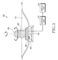
- FIG. 3 is a lateral sectional view illustrating the construction of a contactless battery charger according to the present invention;
- FIG. 4 is a lateral sectional view s illustrating a contactless battery charger according to an embodiment of the present invention while in use; and
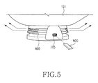
- FIG. 5 is a perspective view illustrating a connection terminal of a contactless battery charger according to the present invention.
- Hereinafter, a contactless battery charger according to a preferred embodiment of the present invention will be described with reference to the accompanying drawings. In the drawings, the same or similar elements are denoted by the same reference numerals even though they are depicted in different drawings. In the following description, a detailed description of known functions and configurations incorporated herein has been omitted for clarity and conciseness.
- Referring to FIGs. 1 and 2, a
contactless battery charger 100 has a plate-shaped portion so thatnumerous terminals 10 andbattery packs 20 can be placed thereon regardless of their type, and is adapted to simultaneously chargenumerous battery packs 20 in a contactless manner. - The principle of contactless charging will now be briefly described. The
charger 100 has a charger-side induction coil 103, and thebattery packs 20 have battery-side induction coils 11. When thecharger 100 is turned on, a voltage is applied to the charger-side induction coil 103 for establishing a magnetic field around it. As a result, mutual electromagnetic induction occurs at the battery-side induction coils 11, which are adjacent to the charger-side induction coil 103, and induced electromotive force is generated by the battery-side induction coil 11 according to Faraday's law. The AC voltage of the induced electromotive force is converted into a DC voltage by rectification circuits (not shown) inside the battery packs. The DC voltage is applied to the numerous charging units for charging thebattery packs 20. - Referring to FIGs. 3 and 4, the
charger 100 has adepression 101, the depth of which gradually increases towards the center up to a predetermined value, so thatnumerous battery packs 20 andterminals 10 can be placed thereon. Thecharger 100 incorporates a short-distance communication module 600 for short-distance transmission/reception with theterminals 10. - Referring to FIG. 4, the
charger 100 has anultraviolet sterilizer 200 positioned on its top and anultrasonic cleaner 300 positioned adjacent to thesterilizer 200. Thesterilizer 200 has aultraviolet lamp 201 for radiating ultraviolet rays A1 towards theportable terminal 10 for sterilizing them. Theultrasonic cleaner 300 has an ultrasonic vibrator (not shown) for generating ultrasonic vibration and radiating it towards theterminals 10 for cleaning them. - Referring to FIGs. 3 and 4, the
depression 101 of thecharger 100 has a radiation region for ultrasonic rays A1 radiated from theultrasonic lamp 201 and a vibration region for ultrasonic vibration generated by the ultrasonic vibrator (not shown). Theultraviolet sterilizer 200 and theultrasonic cleaner 300 are rotated in the upper region of thecharger 100 by a driving motor (not shown), which is positioned inside thecharger 100. - Referring to FIG. 1, the
charger 100 has acylindrical speaker device 400 positioned on its lower portion for playing music files stored on theterminals 10. - Referring to FIG. 2, the
charger 100 has anannular pad 102 extending along the outer periphery of the plate-shaped portion so that theterminals 10 are inclined towards the center of thecharger 100. - Referring to FIGs. 3 and 4, the
charger 100 includes a charger-side induction coil 103, acontrol unit 120, and adisplay unit 130. - The charger-
side induction coil 103 is positioned at the center of thecharger 100 in a cylindrical shape. When thecharger 100 is turned on, a voltage is applied to the charger-side induction coil 103 for establishing a magnetic field around it. As a result, mutual electromagnetic induction occurs at the battery-side induction coils 11, and the AC voltage of induced electromotive force is converted into a DC voltage by rectification circuits (not shown) inside thebattery packs 20. Thecontrol unit 120 controls the charging current based on the rated capacity required by thebattery packs 20. Thedisplay unit 130 monitors the charged conditions of thebattery packs 20 during charging and displays corresponding results. - Referring to FIG. 5, the
charger 100 has aconnection terminal 105, which is connected to anexternal device 500 for supplying power to thecharger 100. - The operation of the contactless battery charger according to a preferred embodiment of the present invention, which is constructed as above, will now be described in detail with reference to FIGs. 1 to 5.
- Referring to FIGs. 1 to 5, when the
contactless battery charger 100 is used to chargenumerous terminals 10, theconnection terminal 105, preferably positioned on the lower portion of thecharger 100, is connected to anexternal device 500. Thecharger 100 is then supplied with power from theexternal device 500. - Referring to FIGs. 3 and 4, the
charger 100 has adepression 101, the depth of which gradually increases towards the center up to a predetermined value, and anannular pad 102 extending along the outer periphery of the plate-shaped portion of thecharger 100 so thatportable terminals 10 are inclined towards the center when placed on thedepression 101. - Referring to FIG. 2, when
battery packs 20 mounted onportable terminals 10 are to be charged, theportable terminals 10 are placed on theannular pad 102. Since, theannular pad 102 of thecharger 100 is foldable, numerousportable terminals 10 can be placed thereon. - Referring to FIGs. 3 and 4, the
charger 100 has a charger-side induction coil 103 positioned at its center. - The
charger 100 has a cylindrical shape, along the circumference of which the charger-side induction coil 103 is positioned. - When
portable terminals 10 are placed on thecharger 100, they are inclined towards the center of thecharger 10. - Referring to FIG. 4, the charger-
side induction coil 103 is connected to the battery-side induction coils 11 in a contactless manner. When thecharger 100 is turned on, a voltage is applied to the charger-side induction coil 103 for establishing a magnetic field around it. As a result, mutual electromagnetic induction occurs at the battery-side induction coils 11, and the AC voltage of induced electromotive force is converted into a DC voltage by rectification circuits (not shown) inside the battery packs 20. The battery packs 20 are charged in this manner. - The
control unit 120 of thecharger 100 controls the charging current based on the rated capacity required by the battery packs 20. Thedisplay unit 130 monitors the charged condition of the battery packs 20 during charging and displays the result. - Referring to FIG. 4, the
charger 100 has anultraviolet sterilizer 200 positioned on the top of the adjacentultrasonic cleaner 300 for sterilizing and cleaning the surface of theportable terminals 10. Particularly, theultraviolet sterilizer 200 has anultrasonic lamp 201, which radiates ultrasonic rays A1 towards the surface of numerous portable terminals on theannular pad 102 and sterilizes them. Theultrasonic cleaner 300 has a ultrasonic vibrator (not shown), which generates ultrasonic vibration for cleaning theterminals 10. - The
depression 101 on the upper surface of thecharger 100 has a radiation region for ultrasonic rays A1 radiated from theultrasonic lamp 201 and a vibration region for ultrasonic vibration generated by the ultrasonic vibrator (not shown). - The
ultraviolet sterilizer 200 and theultrasonic cleaner 300 are rotated by a driving motor (not shown), which is positioned inside thecharger 100. - Referring to FIGs. 2 and 4, the
charger 100 has aspeaker device 400 positioned on its lower portion. When a music file stored in aportable terminal 10 is to be played, data signals of the music file are transmitted to the short-distance communication module 600 of thecharger 100 so that thespeaker device 400 plays music based on the received signals. - As such, the
charger 100 can play music files while charging numerous portable terminals. - While the invention has been shown and described with reference to certain preferred embodiments thereof, it will be understood by those skilled in the art that various changes in form and details may be made therein without departing from the scope of the invention as defined by the appended claims. For example, the present invention is applicable to all types of portable terminals.
Claims (10)
- A contactless battery charger for charging battery packs mounted on portable terminals, the charger comprising a plate-shaped portion gradually depressed towards a center of the charger up to a predetermined depth so that numerous portable terminals and battery packs can be placed on the plate-shaped portion for simultaneously charging the battery packs in a contactless mode.
- The contactless battery charger as claimed in claim 1, further comprising an ultraviolet sterilizer having an ultraviolet lamp for radiating ultraviolet rays to the portable terminals for sterilizing the portable terminals, an ultrasonic cleaner having an ultrasonic vibrator for cleaning the portable terminals by using vibration of ultrasonic waves.
- The contactless battery charger as claimed in claim 2, wherein the ultraviolet sterilizer is positioned on an upper portion and the ultrasonic cleaner is positioned adjacent to the ultrasonic sterilizer.
- The contactless battery charger as claimed in one of claims 1 to 3, wherein a space is defined above an upper surface of the charger with a predetermined depth so that the portable terminals can be placed in the space, and the space provides a radiation region for an ultraviolet lamp and a vibration region for an ultrasonic vibrator.
- The contactless battery charger as claimed in one of claims 1 to 4, further comprising a driving motor for rotating an ultraviolet sterilizer and an ultrasonic cleaner in an upper region of the charger.
- The contactless battery charger as claimed in one of claims 1 to 5, further comprising a cylindrical speaker device positioned inside a lower portion of the charger.
- The contactless battery charger as claimed in one of claims 1 to 6, further comprising a short-distance communication module for transmitting/receiving data to/from the portable terminals during charging.
- The contactless battery charger as claimed in one of claims 1 to 7, further comprising an annular pad extending along an outer periphery of the plate-shaped portion so that the terminals are inclined towards the center of the charger.
- The contactless battery charger as claimed in one of claims 1 to 8, further comprising:a cylindrical charger-side induction coil for establishing a magnetic field around the charger-side induction coil when the charger is supplied with power and a voltage is applied to the charger-side induction coil, a mutual electromagnetic induction occurring at battery-side induction coils by the magnetic field, and an AC voltage of induced electromotive force being converted into a DC voltage by rectification circuits inside the battery packs and charging the battery packs;a control unit for controlling a charging current based on a rated capacity required by the battery packs; anda display unit for monitoring charged conditions of the battery packs during charging and displaying corresponding results.
- The contactless battery charger as claimed in one of claims 1 to 9, further comprising a connection terminal for electrical connection with an external device.
Applications Claiming Priority (1)
| Application Number | Priority Date | Filing Date | Title |
|---|---|---|---|
| KR1020050075732A KR100724962B1 (en) | 2005-08-18 | 2005-08-18 | Solid state battery charger |
Publications (2)
| Publication Number | Publication Date |
|---|---|
| EP1763120A2 true EP1763120A2 (en) | 2007-03-14 |
| EP1763120A3 EP1763120A3 (en) | 2013-04-03 |
Family
ID=37685166
Family Applications (1)
| Application Number | Title | Priority Date | Filing Date |
|---|---|---|---|
| EP06119074A Withdrawn EP1763120A3 (en) | 2005-08-18 | 2006-08-17 | Contactless Battery Charger |
Country Status (4)
| Country | Link |
|---|---|
| US (1) | US7622892B2 (en) |
| EP (1) | EP1763120A3 (en) |
| KR (1) | KR100724962B1 (en) |
| CN (1) | CN100487971C (en) |
Cited By (2)
| Publication number | Priority date | Publication date | Assignee | Title |
|---|---|---|---|---|
| GB2472769A (en) * | 2009-08-05 | 2011-02-23 | Mclaren Applied Technologies Ltd | Contactless charging system with priority consideration |
| WO2021156123A1 (en) * | 2020-02-03 | 2021-08-12 | Koninklijke Philips N.V. | Cleaning and charging portable x-ray detectors |
Families Citing this family (28)
| Publication number | Priority date | Publication date | Assignee | Title |
|---|---|---|---|---|
| KR100819753B1 (en) * | 2007-07-13 | 2008-04-08 | 주식회사 한림포스텍 | Contactless charging system for battery pack solution and its control method |
| US20090075704A1 (en) * | 2007-09-18 | 2009-03-19 | Kevin Peichih Wang | Mobile communication device with charging module |
| USD611898S1 (en) | 2009-07-17 | 2010-03-16 | Lin Wei Yang | Induction charger |
| HK1129811A2 (en) * | 2009-07-20 | 2009-12-04 | Nomenta Industries (Hk) Ltd. | Charging device and connection element |
| USD611900S1 (en) | 2009-07-31 | 2010-03-16 | Lin Wei Yang | Induction charger |
| USD611899S1 (en) | 2009-07-31 | 2010-03-16 | Lin Wei Yang | Induction charger |
| US8258745B2 (en) * | 2009-09-10 | 2012-09-04 | Syntheon, Llc | Surgical sterilizer with integrated battery charging device |
| US8278873B2 (en) * | 2009-09-10 | 2012-10-02 | Syntheon, Llc | Surgical sterilizer with integrated battery charging device |
| WO2011035104A1 (en) * | 2009-09-17 | 2011-03-24 | Sanuwave, Inc. | Methods and devices for cleaning and sterilization with shock waves |
| CN101951004A (en) * | 2010-10-14 | 2011-01-19 | 朱亚林 | Multifunctional disinfecting and charging device for mobile phones |
| US10149711B2 (en) | 2012-03-30 | 2018-12-11 | Depuy Mitek, Llc | Surgical impact tool |
| CN104638695B (en) * | 2013-11-11 | 2020-02-28 | 中兴通讯股份有限公司 | Wireless charging method for mobile terminal, charging emission panel and wireless charging device |
| CN104638773A (en) * | 2013-11-14 | 2015-05-20 | 中兴通讯股份有限公司 | Wireless charging device and operation method thereof |
| USD722959S1 (en) * | 2013-12-28 | 2015-02-24 | Intel Corporation | Wireless charging device |
| KR20150109835A (en) * | 2014-03-21 | 2015-10-02 | 주식회사 레이언스 | Intraoral sensor and intraoral sensing system using the same |
| CN104009524A (en) * | 2014-06-12 | 2014-08-27 | 苏州晶世达光电科技有限公司 | Charging device for wearable intelligent electronic device |
| USD748575S1 (en) * | 2014-12-26 | 2016-02-02 | Intel Corporation | Wireless charging device |
| JP6819966B2 (en) | 2015-06-15 | 2021-01-27 | ヒューマン エクステンションズ リミテッド | Adapters or adapter systems for functionally sterilizing medical devices |
| KR102483835B1 (en) * | 2015-07-06 | 2023-01-03 | 삼성전자주식회사 | Method for transmitting and receving power and electronic device thereof |
| TWI544718B (en) * | 2015-07-27 | 2016-08-01 | 緯創資通股份有限公司 | Wireless charging device and wireless charging method |
| DE112015006853T5 (en) * | 2015-08-28 | 2018-05-24 | Tdk Corporation | Contactless power supply device and contactless power transmission device |
| CN105553022B (en) * | 2016-01-13 | 2019-05-24 | 深圳市龙威盛电子科技有限公司 | Charging terminal |
| KR101904236B1 (en) * | 2016-12-09 | 2018-10-04 | (주)인투케어 | Portable sterilization ball |
| US10201626B1 (en) * | 2017-02-19 | 2019-02-12 | Luke Edward Rapp | Portable ultra violet C sanitizer |
| WO2018186514A1 (en) * | 2017-04-07 | 2018-10-11 | (주)오라컴디스플레이 | Wireless three-dimensional charging device |
| US11885743B2 (en) * | 2020-07-22 | 2024-01-30 | Agar Corporation, Inc. | Fluorescence and scatter and absorption spectroscopic apparatus with a sapphire tube and method for analyzing inline low level hydrocarbon in a flow medium |
| CN113041382A (en) * | 2021-04-02 | 2021-06-29 | 建溢金融财务有限公司 | Intelligent mobile terminal sterilizer |
| USD1081556S1 (en) * | 2023-07-11 | 2025-07-01 | Shenzhen Nanli Technology Trading Co., Ltd. | VR glasses charger |
Citations (2)
| Publication number | Priority date | Publication date | Assignee | Title |
|---|---|---|---|---|
| US5606237A (en) | 1994-04-29 | 1997-02-25 | Delco Electronics Corp. | Inductive coupler characteristic shape |
| DE29718104U1 (en) | 1997-10-14 | 1998-01-02 | Audia Akustik Gmbh | Charging device for hearing aids |
Family Cites Families (9)
| Publication number | Priority date | Publication date | Assignee | Title |
|---|---|---|---|---|
| CN2308198Y (en) | 1997-08-08 | 1999-02-17 | 林超 | Intelligent charger capable of speaking Chinese and English |
| US7126450B2 (en) * | 1999-06-21 | 2006-10-24 | Access Business Group International Llc | Inductively powered apparatus |
| US7612528B2 (en) * | 1999-06-21 | 2009-11-03 | Access Business Group International Llc | Vehicle interface |
| CN1133258C (en) | 2000-07-29 | 2003-12-31 | 深圳市中兴通讯股份有限公司 | Charging method for handset and its intelligent integrated charging device |
| GB0213374D0 (en) * | 2002-06-10 | 2002-07-24 | Univ City Hong Kong | Planar inductive battery charger |
| CN2596682Y (en) | 2002-03-27 | 2003-12-31 | 卢世光 | Hand phone charger with sterilizer |
| JP3719510B2 (en) | 2002-04-08 | 2005-11-24 | アルプス電気株式会社 | Storage room with contactless charger |
| GB2398176B (en) * | 2002-05-13 | 2006-03-08 | Zap Wireless Technologies Ltd | Improvements relating to contact-less power transfer |
| KR100765612B1 (en) * | 2005-04-07 | 2007-10-09 | 엘에스전선 주식회사 | Wireless charger |
-
2005
- 2005-08-18 KR KR1020050075732A patent/KR100724962B1/en not_active Expired - Fee Related
-
2006
- 2006-08-10 US US11/501,963 patent/US7622892B2/en not_active Expired - Fee Related
- 2006-08-17 CN CNB200610115903XA patent/CN100487971C/en not_active Expired - Fee Related
- 2006-08-17 EP EP06119074A patent/EP1763120A3/en not_active Withdrawn
Patent Citations (2)
| Publication number | Priority date | Publication date | Assignee | Title |
|---|---|---|---|---|
| US5606237A (en) | 1994-04-29 | 1997-02-25 | Delco Electronics Corp. | Inductive coupler characteristic shape |
| DE29718104U1 (en) | 1997-10-14 | 1998-01-02 | Audia Akustik Gmbh | Charging device for hearing aids |
Cited By (4)
| Publication number | Priority date | Publication date | Assignee | Title |
|---|---|---|---|---|
| GB2472769A (en) * | 2009-08-05 | 2011-02-23 | Mclaren Applied Technologies Ltd | Contactless charging system with priority consideration |
| GB2472769B (en) * | 2009-08-05 | 2013-01-09 | Mclaren Applied Technologies Ltd | Critically-based charging |
| WO2021156123A1 (en) * | 2020-02-03 | 2021-08-12 | Koninklijke Philips N.V. | Cleaning and charging portable x-ray detectors |
| US11712211B2 (en) | 2020-02-03 | 2023-08-01 | Koninklijke Philips N.V. | Cleaning and charging portable X-ray detectors |
Also Published As
| Publication number | Publication date |
|---|---|
| KR20070021463A (en) | 2007-02-23 |
| CN1917278A (en) | 2007-02-21 |
| KR100724962B1 (en) | 2007-06-04 |
| US7622892B2 (en) | 2009-11-24 |
| US20070046256A1 (en) | 2007-03-01 |
| EP1763120A3 (en) | 2013-04-03 |
| CN100487971C (en) | 2009-05-13 |
Similar Documents
| Publication | Publication Date | Title |
|---|---|---|
| US7622892B2 (en) | Contactless battery charger | |
| EP2332231B1 (en) | Inductive charger and charging method | |
| JP5563501B2 (en) | Non-contact charging battery pack and control method thereof | |
| US8248025B2 (en) | Charging system capable of charging electronic device by electromagnetic induction | |
| US9074761B2 (en) | Composite table lighting structure for wired charging and wireless charging | |
| EP2793359A1 (en) | Wireless charger capable of automatic position adjustment and charging method using same | |
| CN103858307B (en) | Contactless charging battery, contact-less charger | |
| US9570937B2 (en) | Wireless power transmission device | |
| US20090075704A1 (en) | Mobile communication device with charging module | |
| US20090179501A1 (en) | Device cover with embedded power receiver | |
| EP2388886B1 (en) | Wireless charging jacket combined with a battery and wireless charging system thereof | |
| KR20130118413A (en) | Charge apparatus and circuit which can use wired charging method and wireless charging method | |
| CN1323479C (en) | Charging device for battery of mobile communication terminal | |
| CN104348216A (en) | Wireless charger equipped with auxiliary power supply and auxiliary power device | |
| US20220069600A1 (en) | Dual electronic device wireless charger | |
| WO2022046295A1 (en) | Dual electronic device wireless charger | |
| CN109149684A (en) | a wireless charging device | |
| KR101767622B1 (en) | Exterior case of portable electronic device having circuit for contact-less charge | |
| JP2012070566A (en) | Non-contact rechargeable type electrical apparatus and charging system for the same | |
| JPH11178229A (en) | Charger | |
| KR20190103846A (en) | Cordless wireless charger with generator | |
| JP2020178110A (en) | Wireless charging device and its transmitting module and transmitting coil | |
| JP2015002580A (en) | Wireless charging device | |
| KR20120008634A (en) | Improved structured contactless power receiving device and contactless charging system | |
| KR102347219B1 (en) | Wireless magnetic resonant power transfer device and Portable device using the same |
Legal Events
| Date | Code | Title | Description |
|---|---|---|---|
| PUAI | Public reference made under article 153(3) epc to a published international application that has entered the european phase |
Free format text: ORIGINAL CODE: 0009012 |
|
| 17P | Request for examination filed |
Effective date: 20060817 |
|
| AK | Designated contracting states |
Kind code of ref document: A2 Designated state(s): AT BE BG CH CY CZ DE DK EE ES FI FR GB GR HU IE IS IT LI LT LU LV MC NL PL PT RO SE SI SK TR |
|
| AX | Request for extension of the european patent |
Extension state: AL BA HR MK YU |
|
| RAP1 | Party data changed (applicant data changed or rights of an application transferred) |
Owner name: SAMSUNG ELECTRONICS CO., LTD. |
|
| RIC1 | Information provided on ipc code assigned before grant |
Ipc: H02J 7/00 20060101ALI20121108BHEP Ipc: H02J 7/02 20060101AFI20121108BHEP |
|
| PUAL | Search report despatched |
Free format text: ORIGINAL CODE: 0009013 |
|
| AK | Designated contracting states |
Kind code of ref document: A3 Designated state(s): AT BE BG CH CY CZ DE DK EE ES FI FR GB GR HU IE IS IT LI LT LU LV MC NL PL PT RO SE SI SK TR |
|
| AX | Request for extension of the european patent |
Extension state: AL BA HR MK RS |
|
| RIC1 | Information provided on ipc code assigned before grant |
Ipc: H02J 7/02 20060101AFI20130226BHEP Ipc: H02J 7/00 20060101ALI20130226BHEP |
|
| 17Q | First examination report despatched |
Effective date: 20131021 |
|
| AKX | Designation fees paid |
Designated state(s): DE FR GB |
|
| STAA | Information on the status of an ep patent application or granted ep patent |
Free format text: STATUS: THE APPLICATION IS DEEMED TO BE WITHDRAWN |
|
| 18D | Application deemed to be withdrawn |
Effective date: 20140917 |