EP1762862A1 - Method and device for 3D imaging - Google Patents
Method and device for 3D imaging Download PDFInfo
- Publication number
- EP1762862A1 EP1762862A1 EP05108303A EP05108303A EP1762862A1 EP 1762862 A1 EP1762862 A1 EP 1762862A1 EP 05108303 A EP05108303 A EP 05108303A EP 05108303 A EP05108303 A EP 05108303A EP 1762862 A1 EP1762862 A1 EP 1762862A1
- Authority
- EP
- European Patent Office
- Prior art keywords
- frequency
- modulation
- light
- time interval
- integration time
- Prior art date
- Legal status (The legal status is an assumption and is not a legal conclusion. Google has not performed a legal analysis and makes no representation as to the accuracy of the status listed.)
- Withdrawn
Links
Images
Classifications
-
- G—PHYSICS
- G01—MEASURING; TESTING
- G01S—RADIO DIRECTION-FINDING; RADIO NAVIGATION; DETERMINING DISTANCE OR VELOCITY BY USE OF RADIO WAVES; LOCATING OR PRESENCE-DETECTING BY USE OF THE REFLECTION OR RERADIATION OF RADIO WAVES; ANALOGOUS ARRANGEMENTS USING OTHER WAVES
- G01S17/00—Systems using the reflection or reradiation of electromagnetic waves other than radio waves, e.g. lidar systems
- G01S17/02—Systems using the reflection of electromagnetic waves other than radio waves
- G01S17/06—Systems determining position data of a target
- G01S17/08—Systems determining position data of a target for measuring distance only
- G01S17/32—Systems determining position data of a target for measuring distance only using transmission of continuous waves, whether amplitude-, frequency-, or phase-modulated, or unmodulated
- G01S17/36—Systems determining position data of a target for measuring distance only using transmission of continuous waves, whether amplitude-, frequency-, or phase-modulated, or unmodulated with phase comparison between the received signal and the contemporaneously transmitted signal
-
- G—PHYSICS
- G01—MEASURING; TESTING
- G01S—RADIO DIRECTION-FINDING; RADIO NAVIGATION; DETERMINING DISTANCE OR VELOCITY BY USE OF RADIO WAVES; LOCATING OR PRESENCE-DETECTING BY USE OF THE REFLECTION OR RERADIATION OF RADIO WAVES; ANALOGOUS ARRANGEMENTS USING OTHER WAVES
- G01S17/00—Systems using the reflection or reradiation of electromagnetic waves other than radio waves, e.g. lidar systems
- G01S17/88—Lidar systems specially adapted for specific applications
- G01S17/89—Lidar systems specially adapted for specific applications for mapping or imaging
- G01S17/894—Three-dimensional [3D] imaging with simultaneous measurement of time-of-flight at a two-dimensional [2D] array of receiver pixels, e.g. time-of-flight cameras or flash lidar
Definitions
- the present invention generally relates to 3D imaging, more specifically to 3D imaging based on spatially resolved phase detection of modulated light waves.
- a 3D imaging system requires depth information about the target scene, i.e. the distances between one or more observed objects and an optical receiver of the system need to be determined.
- the basic principles of three-dimensional imagers are described in detail in EP 1 152 261 A1 and WO 98/10255 .
- 3D imaging systems of this kind use active illumination of the scene with intensity-modulated light.
- the scene is optically imaged onto a two-dimensional pixel array.
- Each pixel detects the modulation phase of the light that has been emitted by the illumination device and reflected or scattered from an object of the scene to the pixel. From this phase, the time lapsed between transmission and echo-return of the transmitted light and hence the distance the light has travelled can be determined for each pixel.
- These data can be used to generate a 3D representation of the scene.
- the term "light” is herein to be understood as including electromagnetic radiation in general and preferably visible, ultraviolet or infrared radiation.
- Systems for creating a 3D representation of a given portion of space have a variety of potential applications in many different fields. Examples are automotive sensor technology (e.g. vehicle occupant detection and classification), robotic sensor technology (e.g. object identification) or safety engineering (e.g. plant monitoring) to name only a few.
- automotive sensor technology e.g. vehicle occupant detection and classification
- robotic sensor technology e.g. object identification
- safety engineering e.g. plant monitoring
- the method for 3D imaging of an actively illuminated target region generally comprises emitting intensity-modulated light into the target region.
- the frequency of the modulation is hereinafter referred to as the modulation frequency.
- the emitted light is scattered and/or reflected in the target region depending on the optical properties of the objects or beings present therein.
- a scattered and/or reflected fraction of the light is detected during an integration time interval by phase-sensitive integration in each pixel of an imaging sensor.
- the modulation phase between the emitted and the detected light is then determined and spatially resolved.
- the modulation frequency is varied over the integration time interval, e.g. according to a predetermined pattern.
- the distance from the latter to the scattering/reflecting object corresponds to half the total distance d.
- the modulation peak in the frequency domain is broader.
- a given energy content of the modulation is thus spread over a broader spectral range, which results in a lower peak and has beneficial impact on electromagnetic compatibility with electronic devices in the neighbourhood.
- the method furthermore allows more robust phase detection in presence of other illumination devices, which use modulation in the same frequency spectrum.
- Illumination devices with a fixed modulation frequency presently operate at approximately 20 MHz.
- the modulation frequency is varied preferably in the range from 18 to 22 MHz, more preferably in the range from 19,5 to 20,5 MHz.
- the modulation frequency can be varied continuously or in discrete steps.
- a broader frequency range may induce a less precise distance determination. The above ranges represent a good compromise between these effects.
- broader or narrower frequency ranges may nevertheless be appropriate.
- the invention further relates to a 3D imaging system.
- a 3D imaging system comprises signal generation means for generating a modulation signal with a variable modulation frequency and an illumination unit operationally connected to the signal generation means for emitting intensity-mediated light with this modulation frequency into the target region.
- an imaging sensor is provided, which is operationally connected to the signal generation means.
- the system further comprises an evaluation unit, which is operationally connected to the signal generation means and the imaging sensor for calculating distance information. It shall be noted that the signal generation means is configured so as to provide a modulation signal with a modulation frequency varying over the integration time interval.
- the evaluation unit further comprises a frequency average builder for providing an average frequency of the modulation frequency over the integration time interval, e.g. using the modulation signal as input.
- the signal generation means can be configured so that the average frequency takes a predetermined value. The average frequency thus needs not to be determined online but can be stored as a constant value in an internal memory of the system.
- the signal generation means comprises a voltage-controlled oscillator (VCO), a numerically controlled oscillator (NCO) or a multiplexer, which can switch between different values of the modulation frequency.
- VCO voltage-controlled oscillator
- NCO numerically controlled oscillator
- a controller can be provided for controlling the numerically controlled oscillator, respectively the multiplexer by a control signal.
- a frequency average builder operationally connected to the controller can then provide the average frequency of the modulation frequency based on the control signal.
- signal source 12 In the 3D imaging system 10 shown in Fig. 1, signal source 12 generates on its output a modulation signal 14 with a variable frequency.
- the signal source 1 is in this case a voltage-controlled oscillator (VCO) running at a carrier frequency and controlled by a defined signal that varies this frequency.
- VCO voltage-controlled oscillator
- the signal source 12 is connected to the illumination unit, which comprises an illumination driver 16 and a light source 18.
- the illumination driver 16 amplifies the modulation signal 14 to drive the several individual light emitting devices 20 of the light source 18.
- the light source 18 emits an intensity-modulated light wave 22 into the target region, which contains an object 24 to be measured. Light is scattered or reflected on the surface of object 24 and a fraction 26 of the scattered/reflected light is directed onto the pixel array 28 of the three-dimensionally sensitive imager 30.
- the imager 30 (camera) is at the same time fed with a demodulation signal 32, which is derived from the modulation signal by the photo gate driver 34.
- the imager 30 outputs modulation phase information 36 for each pixel of the pixel array 28.
- the frequency measurer and average builder 38 determines the average frequency of the modulation signal 14 by counting the cycles thereof.
- the average frequency is provided to a calculation unit 40 by connection line 42.
- the distance d is outputted at 44, from where it can be fed to other components, such as an image analyser or a microprocessor.
- Fig. 2 shows a slightly different embodiment of a 3D imaging system 10.
- the signal source 12 that generates the modulation signal 14 with variable frequency is a numerically controlled oscillator (NCO) or a multiplexer switching between different frequency values operated by a controller 46 that defines the currently used frequency by means of control signal 48.
- the NCO or multiplexer is connected to the illumination unit, to which it provides the modulation signal 14. Illumination and modulation phase detection is performed in the same way as in the above-described embodiment.
- the average frequency is determined differently.
- the frequency average builder 38 is connected to the controller 46 and determines the different modulation frequencies of the modulation signal 14 outputted by the NCO or multiplexer based on the control signal 49.
- the frequency average builder 38 can, for instance, store the different values of the modulation frequency, which are identified by means of the control signal 49. If the time steps for the different modulation frequencies vary during the integration time, they are preferably also stored. At the end of each integration time interval, the average frequency is determined.
- the weighting factors can be normalised, i.e. multiplied by a common factor such that their sum equals 1, which simplifies the preceding equation.
Landscapes
- Physics & Mathematics (AREA)
- Engineering & Computer Science (AREA)
- Electromagnetism (AREA)
- Computer Networks & Wireless Communication (AREA)
- General Physics & Mathematics (AREA)
- Radar, Positioning & Navigation (AREA)
- Remote Sensing (AREA)
- Length Measuring Devices By Optical Means (AREA)
- Optical Radar Systems And Details Thereof (AREA)
- Testing, Inspecting, Measuring Of Stereoscopic Televisions And Televisions (AREA)
Abstract
A method for 3D imaging of an actively illuminated target region comprises emitting intensity-modulated light at a variable modulation frequency into the target region. The emitted light is scattered/reflected in the target region depending on the optical properties of the objects or beings present therein. A scattered and/or reflected fraction of the light is detected during an integration time interval by phase-sensitive integration in each pixel of an imaging sensor. The modulation phase between the emitted and the detected light is determined and spatially resolved. Distance information is calculated based on the spatially resolved modulation phase and an average frequency of the modulation frequency.
Description
- The present invention generally relates to 3D imaging, more specifically to 3D imaging based on spatially resolved phase detection of modulated light waves.
- As opposed to conventional 2D imaging, a 3D imaging system requires depth information about the target scene, i.e. the distances between one or more observed objects and an optical receiver of the system need to be determined. The basic principles of three-dimensional imagers are described in detail in
EP 1 152 261 A1 andWO 98/10255 - Systems for creating a 3D representation of a given portion of space have a variety of potential applications in many different fields. Examples are automotive sensor technology (e.g. vehicle occupant detection and classification), robotic sensor technology (e.g. object identification) or safety engineering (e.g. plant monitoring) to name only a few.
- Especially in the automotive field, electronics developers are increasingly faced with the problem of electromagnetic interference between different components of electronic car equipment. Developers therefore look for new solutions, which can help to reduce potential conflicts related to interference of electronic devices.
- It is an object of the present invention to provide an improved method for for 3D imaging of an actively illuminated scene. This object is achieved by a method as claimed in claim 1.
- The method for 3D imaging of an actively illuminated target region generally comprises emitting intensity-modulated light into the target region. The frequency of the modulation is hereinafter referred to as the modulation frequency. The emitted light is scattered and/or reflected in the target region depending on the optical properties of the objects or beings present therein. A scattered and/or reflected fraction of the light is detected during an integration time interval by phase-sensitive integration in each pixel of an imaging sensor. The modulation phase between the emitted and the detected light is then determined and spatially resolved. As will be appreciated, the modulation frequency is varied over the integration time interval, e.g. according to a predetermined pattern. According to the invention, distance information is calculated based on the spatially resolved modulation phase and an average frequency of said modulation frequency over said integration time interval. For each pixel, the distance from the light source to the scattering/reflecting object and can be calculated. Additionally or alternatively, the distance from the scattering object to the imager pixel or the total distance can be calculated. For each pixel, the total distance travelled by the light is determined as:

where d is the total distance, c is the speed of light, is the modulation phase between the emitted and the detected light in radians and f is the average modulation frequency. When the light source is located next to the imaging sensor, the distance from the latter to the scattering/reflecting object corresponds to half the total distance d. - It will be appreciated that with variable modulation frequency, the modulation peak in the frequency domain is broader. A given energy content of the modulation is thus spread over a broader spectral range, which results in a lower peak and has beneficial impact on electromagnetic compatibility with electronic devices in the neighbourhood. The method furthermore allows more robust phase detection in presence of other illumination devices, which use modulation in the same frequency spectrum. Illumination devices with a fixed modulation frequency presently operate at approximately 20 MHz. In the present method, the modulation frequency is varied preferably in the range from 18 to 22 MHz, more preferably in the range from 19,5 to 20,5 MHz. The modulation frequency can be varied continuously or in discrete steps. As a general rule, it can be said that the detection robustness increases with the width of the frequency range. On the other hand, a broader frequency range may induce a less precise distance determination. The above ranges represent a good compromise between these effects. Depending on the application, broader or narrower frequency ranges may nevertheless be appropriate.
- The invention further relates to a 3D imaging system. Such a system comprises signal generation means for generating a modulation signal with a variable modulation frequency and an illumination unit operationally connected to the signal generation means for emitting intensity-mediated light with this modulation frequency into the target region. For detecting a scattered and/or reflected part of the light during an integration time interval and for determining a spatially resolved modulation phase between emitted light and detected light, an imaging sensor is provided, which is operationally connected to the signal generation means. The system further comprises an evaluation unit, which is operationally connected to the signal generation means and the imaging sensor for calculating distance information. It shall be noted that the signal generation means is configured so as to provide a modulation signal with a modulation frequency varying over the integration time interval. The evaluation unit further comprises a frequency average builder for providing an average frequency of the modulation frequency over the integration time interval, e.g. using the modulation signal as input. Alternatively, the signal generation means can be configured so that the average frequency takes a predetermined value. The average frequency thus needs not to be determined online but can be stored as a constant value in an internal memory of the system.
- Advantageously, the signal generation means comprises a voltage-controlled oscillator (VCO), a numerically controlled oscillator (NCO) or a multiplexer, which can switch between different values of the modulation frequency. In the case of an NCO or a multiplexer, a controller can be provided for controlling the numerically controlled oscillator, respectively the multiplexer by a control signal. A frequency average builder operationally connected to the controller can then provide the average frequency of the modulation frequency based on the control signal.
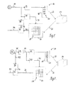
- Further details and advantages of the present invention will be apparent from the following detailed description of several not limiting embodiments with reference to the attached drawings, wherein:
- Fig. 1: is a block schematic diagram of a first embodiment of a 3D imager;
- Fig. 2: is a block schematic diagram of a second embodiment of a 3D imager.
- In the
3D imaging system 10 shown in Fig. 1,signal source 12 generates on its output amodulation signal 14 with a variable frequency. The signal source 1 is in this case a voltage-controlled oscillator (VCO) running at a carrier frequency and controlled by a defined signal that varies this frequency. Thesignal source 12 is connected to the illumination unit, which comprises anillumination driver 16 and alight source 18. - The
illumination driver 16 amplifies themodulation signal 14 to drive the several individuallight emitting devices 20 of thelight source 18. Thelight source 18 emits an intensity-modulatedlight wave 22 into the target region, which contains anobject 24 to be measured. Light is scattered or reflected on the surface ofobject 24 and afraction 26 of the scattered/reflected light is directed onto thepixel array 28 of the three-dimensionallysensitive imager 30. The imager 30 (camera) is at the same time fed with ademodulation signal 32, which is derived from the modulation signal by thephoto gate driver 34. Theimager 30 outputsmodulation phase information 36 for each pixel of thepixel array 28. - For each integration time interval of duration T, the frequency measurer and
average builder 38 determines the average frequency of themodulation signal 14 by counting the cycles thereof. The average frequency f is calculated as f = N l T, where N is the number of cycles in the integration time interval. The average frequency is provided to acalculation unit 40 byconnection line 42. - The
calculation unit 40 calculates the distance d for each pixel with thephase information 36 and the average frequency f, according to the equation:
where d is the total distance, c is the speed of light, is the modulation phase in radians between the emitted and the light detected in the respective pixel. The distance d is outputted at 44, from where it can be fed to other components, such as an image analyser or a microprocessor. - Fig. 2 shows a slightly different embodiment of a
3D imaging system 10. Thesignal source 12 that generates themodulation signal 14 with variable frequency is a numerically controlled oscillator (NCO) or a multiplexer switching between different frequency values operated by acontroller 46 that defines the currently used frequency by means ofcontrol signal 48. The NCO or multiplexer is connected to the illumination unit, to which it provides themodulation signal 14. Illumination and modulation phase detection is performed in the same way as in the above-described embodiment. - The average frequency, however, is determined differently. The frequency
average builder 38 is connected to thecontroller 46 and determines the different modulation frequencies of themodulation signal 14 outputted by the NCO or multiplexer based on thecontrol signal 49. The frequencyaverage builder 38 can, for instance, store the different values of the modulation frequency, which are identified by means of thecontrol signal 49. If the time steps for the different modulation frequencies vary during the integration time, they are preferably also stored. At the end of each integration time interval, the average frequency is determined. In case there are n time steps of same duration, the average frequency f can be calculated according to:
where f1, f2,..., fn are the respective modulation frequencies during the n time steps. - In case the time steps have different duration, the average frequency f can be calculated as a weighed average of the frequencies of the individual time steps:

where f1, f2,..., fn are the respective modulation frequencies during the n time steps and a1, a2,..., an are weighting factors, e.g. corresponding to the respective durations of the individual time steps. The weighting factors can be normalised, i.e. multiplied by a common factor such that their sum equals 1, which simplifies the preceding equation.
Claims (9)
- A method for 3D imaging of a target region, comprising the steps of:emitting light into said target region; said emitted light being intensity-modulated at a modulation frequency;detecting a scattered and/or reflected part of said light during an integration time interval;determining a spatially resolved modulation phase between emitted light and detected light;varying said modulation frequency over said integration time interval; andcalculating distance information;characterised in that
said distance information is calculated based on said spatially resolved modulation phase and an average frequency of said modulation frequency over said integration time interval. - A method according to claim 1, wherein said modulation frequency is continuously varied over said integration time interval.
- A method according to claim 1, wherein said modulation frequency is varied in discrete steps over said integration time interval.
- A method according to claim 3, wherein said discrete steps have equal duration and/or equal step height.
- A 3D imaging system comprising:signal generation means for generating a modulation signal with a variable modulation frequency;an illumination unit operationally connected to said signal generation means for emitting intensity-modulated light with said modulation frequency into a target region;an imaging sensor operationally connected to said signal generation means for detecting a scattered and/or reflected part of said light during an integration time interval and for determining a spatially resolved modulation phase between emitted light and detected light;an evaluation unit operationally connected to said signal generation means and said imaging sensor for calculating distance informationcharacterised in that said evaluation unit comprises a frequency average builder for providing an average frequency of said variable modulation frequency over said integration time interval, said distance information being calculated based on said spatially resolved modulation phase and said average frequency.
- A 3D imaging system according to claim 5, wherein said signal generation means comprises a voltage-controlled oscillator.
- A 3D imaging system according to any one of claims 5 to 8, wherein said signal generation means comprises a multiplexer for switching between different values of said modulation frequency and a controller for controlling said multiplexer by a control signal.
- A 3D imaging system according to claim 5 or 6, wherein said signal generation means comprises a numerically controlled oscillator and a controller for controlling said numerically controlled oscillator by a control signal.
- A 3D imaging system according to claim 7 or 8, wherein said controller is operationally connected to said frequency average builder, said frequency average builder being able to provide said average frequency of said modulation frequency based on said control signal.
Priority Applications (6)
| Application Number | Priority Date | Filing Date | Title |
|---|---|---|---|
| EP05108303A EP1762862A1 (en) | 2005-09-09 | 2005-09-09 | Method and device for 3D imaging |
| EP06793149A EP1934631B1 (en) | 2005-09-09 | 2006-09-01 | Method and device for 3d imaging |
| US12/066,318 US7609367B2 (en) | 2005-09-09 | 2006-09-01 | Method and device for 3D imaging |
| PCT/EP2006/065927 WO2007028774A1 (en) | 2005-09-09 | 2006-09-01 | Method and device for 3d imaging |
| DE602006010725T DE602006010725D1 (en) | 2005-09-09 | 2006-09-01 | METHOD AND DEVICE FOR 3D IMAGING |
| JP2008529615A JP2009508096A (en) | 2005-09-09 | 2006-09-01 | 3D imaging method and apparatus |
Applications Claiming Priority (1)
| Application Number | Priority Date | Filing Date | Title |
|---|---|---|---|
| EP05108303A EP1762862A1 (en) | 2005-09-09 | 2005-09-09 | Method and device for 3D imaging |
Publications (1)
| Publication Number | Publication Date |
|---|---|
| EP1762862A1 true EP1762862A1 (en) | 2007-03-14 |
Family
ID=35741078
Family Applications (2)
| Application Number | Title | Priority Date | Filing Date |
|---|---|---|---|
| EP05108303A Withdrawn EP1762862A1 (en) | 2005-09-09 | 2005-09-09 | Method and device for 3D imaging |
| EP06793149A Ceased EP1934631B1 (en) | 2005-09-09 | 2006-09-01 | Method and device for 3d imaging |
Family Applications After (1)
| Application Number | Title | Priority Date | Filing Date |
|---|---|---|---|
| EP06793149A Ceased EP1934631B1 (en) | 2005-09-09 | 2006-09-01 | Method and device for 3d imaging |
Country Status (5)
| Country | Link |
|---|---|
| US (1) | US7609367B2 (en) |
| EP (2) | EP1762862A1 (en) |
| JP (1) | JP2009508096A (en) |
| DE (1) | DE602006010725D1 (en) |
| WO (1) | WO2007028774A1 (en) |
Cited By (2)
| Publication number | Priority date | Publication date | Assignee | Title |
|---|---|---|---|---|
| NL1033590C2 (en) * | 2007-03-26 | 2008-09-29 | Maasland Nv | Unmanned vehicle for delivering feed to an animal. |
| NL1033591C2 (en) * | 2007-03-26 | 2008-09-29 | Maasland Nv | Unmanned vehicle for moving manure. |
Families Citing this family (6)
| Publication number | Priority date | Publication date | Assignee | Title |
|---|---|---|---|---|
| EP1903299A1 (en) * | 2006-09-20 | 2008-03-26 | IEE INTERNATIONAL ELECTRONICS & ENGINEERING S.A. | Method and system for acquiring a 3-D image of a scene |
| EP2073035A1 (en) | 2007-12-18 | 2009-06-24 | IEE INTERNATIONAL ELECTRONICS & ENGINEERING S.A. | Recording of 3D images of a scene |
| KR101812035B1 (en) * | 2010-11-30 | 2017-12-26 | 삼성전자 주식회사 | Image sensor and method for obtaining color image and depth image simultaneously |
| GB2492848A (en) * | 2011-07-15 | 2013-01-16 | Softkinetic Sensors Nv | Optical distance measurement |
| SE537621C2 (en) * | 2013-09-10 | 2015-08-11 | Scania Cv Ab | Detection of objects using a 3D camera and a radar |
| KR102232390B1 (en) * | 2019-07-15 | 2021-03-26 | 한국과학기술원 | Three dimensional image generating method and apparatus |
Citations (5)
| Publication number | Priority date | Publication date | Assignee | Title |
|---|---|---|---|---|
| EP0527585A1 (en) * | 1991-08-12 | 1993-02-17 | Hughes Aircraft Company | Semiconductor laser pulse compression radar system |
| DE19704496A1 (en) * | 1996-09-05 | 1998-03-12 | Rudolf Prof Dr Ing Schwarte | Method and device for determining the phase and / or amplitude information of an electromagnetic wave |
| WO1998010255A1 (en) | 1996-09-05 | 1998-03-12 | Rudolf Schwarte | Method and device for determining the phase- and/or amplitude data of an electromagnetic wave |
| US5877851A (en) * | 1997-09-24 | 1999-03-02 | The United States Of America As Represented By The Secretary Of The Army | Scannerless ladar architecture employing focal plane detector arrays and FM-CW ranging theory |
| EP1152261A1 (en) | 2000-04-28 | 2001-11-07 | CSEM Centre Suisse d'Electronique et de Microtechnique SA | Device and method for spatially resolved photodetection and demodulation of modulated electromagnetic waves |
Family Cites Families (11)
| Publication number | Priority date | Publication date | Assignee | Title |
|---|---|---|---|---|
| US5194906A (en) * | 1990-09-10 | 1993-03-16 | Kabushiki Kaisha Topcon | Distance measuring device |
| US5488627A (en) * | 1993-11-29 | 1996-01-30 | Lexmark International, Inc. | Spread spectrum clock generator and associated method |
| JP4034440B2 (en) * | 1998-10-16 | 2008-01-16 | オリンパス株式会社 | Video equipment |
| JP2000224392A (en) * | 1999-01-29 | 2000-08-11 | Canon Inc | Imaging device, method, and computer-readable storage medium |
| US20020071109A1 (en) * | 2000-07-24 | 2002-06-13 | Christopher Allen | Laser radar system and method |
| JP3666648B2 (en) * | 2001-01-11 | 2005-06-29 | 日本電気株式会社 | Clock frequency modulation circuit and electronic apparatus equipped with the modulation circuit |
| JP2003150660A (en) * | 2001-11-14 | 2003-05-23 | Nec Corp | Design method of electronic device having clock frequency modulation circuit |
| JP3832441B2 (en) * | 2002-04-08 | 2006-10-11 | 松下電工株式会社 | Spatial information detection device using intensity-modulated light |
| DE10242777A1 (en) * | 2002-09-14 | 2004-04-08 | Robert Bosch Gmbh | Method for determining a distance and distance measuring device |
| TWI252393B (en) * | 2003-09-08 | 2006-04-01 | Samsung Electronics Co Ltd | A spread spectrum clock generator and method and system of generating a spread spectrum clock |
| JP2005223770A (en) * | 2004-02-09 | 2005-08-18 | Nec Engineering Ltd | Electronic apparatus and its electromagnetic interference preventing method |
-
2005
- 2005-09-09 EP EP05108303A patent/EP1762862A1/en not_active Withdrawn
-
2006
- 2006-09-01 US US12/066,318 patent/US7609367B2/en active Active
- 2006-09-01 WO PCT/EP2006/065927 patent/WO2007028774A1/en not_active Ceased
- 2006-09-01 JP JP2008529615A patent/JP2009508096A/en active Pending
- 2006-09-01 EP EP06793149A patent/EP1934631B1/en not_active Ceased
- 2006-09-01 DE DE602006010725T patent/DE602006010725D1/en active Active
Patent Citations (5)
| Publication number | Priority date | Publication date | Assignee | Title |
|---|---|---|---|---|
| EP0527585A1 (en) * | 1991-08-12 | 1993-02-17 | Hughes Aircraft Company | Semiconductor laser pulse compression radar system |
| DE19704496A1 (en) * | 1996-09-05 | 1998-03-12 | Rudolf Prof Dr Ing Schwarte | Method and device for determining the phase and / or amplitude information of an electromagnetic wave |
| WO1998010255A1 (en) | 1996-09-05 | 1998-03-12 | Rudolf Schwarte | Method and device for determining the phase- and/or amplitude data of an electromagnetic wave |
| US5877851A (en) * | 1997-09-24 | 1999-03-02 | The United States Of America As Represented By The Secretary Of The Army | Scannerless ladar architecture employing focal plane detector arrays and FM-CW ranging theory |
| EP1152261A1 (en) | 2000-04-28 | 2001-11-07 | CSEM Centre Suisse d'Electronique et de Microtechnique SA | Device and method for spatially resolved photodetection and demodulation of modulated electromagnetic waves |
Cited By (6)
| Publication number | Priority date | Publication date | Assignee | Title |
|---|---|---|---|---|
| NL1033590C2 (en) * | 2007-03-26 | 2008-09-29 | Maasland Nv | Unmanned vehicle for delivering feed to an animal. |
| NL1033591C2 (en) * | 2007-03-26 | 2008-09-29 | Maasland Nv | Unmanned vehicle for moving manure. |
| WO2008118006A1 (en) | 2007-03-26 | 2008-10-02 | Maasland N.V. | Unmanned vehicle for displacing dung |
| WO2008118004A1 (en) * | 2007-03-26 | 2008-10-02 | Maasland N.V. | Unmanned vehicle for supplying feed to an animal |
| AU2008230227B2 (en) * | 2007-03-26 | 2012-05-31 | Maasland N.V. | Unmanned vehicle for supplying feed to an animal |
| US8397670B2 (en) * | 2007-03-26 | 2013-03-19 | Maasland N.V. | Unmanned vehicle for supplying feed to an animal |
Also Published As
| Publication number | Publication date |
|---|---|
| WO2007028774A1 (en) | 2007-03-15 |
| EP1934631A1 (en) | 2008-06-25 |
| EP1934631B1 (en) | 2009-11-25 |
| JP2009508096A (en) | 2009-02-26 |
| US7609367B2 (en) | 2009-10-27 |
| US20080239280A1 (en) | 2008-10-02 |
| DE602006010725D1 (en) | 2010-01-07 |
Similar Documents
| Publication | Publication Date | Title |
|---|---|---|
| EP2378310B1 (en) | Time of flight camera unit and optical surveillance system | |
| EP2594959B1 (en) | System and method for multi TOF camera operation using phase hopping | |
| US9753128B2 (en) | Multi-path compensation using multiple modulation frequencies in time of flight sensor | |
| RU2600495C2 (en) | Optical measuring device for vehicle and appropriate vehicle | |
| US7570347B2 (en) | Chirped amplitude modulation ladar | |
| US10085310B2 (en) | Application using a single photon avalanche diode (SPAD) | |
| US7379163B2 (en) | Method and system for automatic gain control of sensors in time-of-flight systems | |
| US20100002912A1 (en) | Facial feature evaluation based on eye location | |
| JP5655133B2 (en) | Spatial information detector | |
| US9894347B2 (en) | 3D image acquisition apparatus and method of driving the same | |
| JP2006517659A (en) | Automotive device used for 3D detection of inside / outside scene of automobile | |
| EP3660540B1 (en) | Filtering continuous-wave time-of-flight measurements, based on coded modulation images | |
| EP3408683A1 (en) | Optical phasograms for ladar vibrometry | |
| EP2264481A1 (en) | Method and device for acquiring a range image | |
| JP2000509485A (en) | Object position detection method | |
| EP1934631B1 (en) | Method and device for 3d imaging | |
| KR20140145481A (en) | Tof camera for vehicle | |
| JP2021513643A (en) | Methods and devices for detecting critical lateral movements | |
| WO2011000815A1 (en) | Range camera and range image acquisition method | |
| CN112262324A (en) | Operating method, control unit, lidar system and device for a lidar system | |
| CN109791203A (en) | Method for carrying out the optical sensor of range measurement and/or tachometric survey, the system of mobility monitoring for autonomous vehicle and the mobility for autonomous vehicle monitor | |
| KR20060013500A (en) | Distance sensing system | |
| US11754711B2 (en) | Frequency chirp for lidar for high-velocity targets | |
| US20240241233A1 (en) | Method for operating a detection device, detection device, and vehicle comprising at least one detection device | |
| US20220291362A1 (en) | Optoelectronic device and method for distance measurement |
Legal Events
| Date | Code | Title | Description |
|---|---|---|---|
| PUAI | Public reference made under article 153(3) epc to a published international application that has entered the european phase |
Free format text: ORIGINAL CODE: 0009012 |
|
| AK | Designated contracting states |
Kind code of ref document: A1 Designated state(s): AT BE BG CH CY CZ DE DK EE ES FI FR GB GR HU IE IS IT LI LT LU LV MC NL PL PT RO SE SI SK TR |
|
| AX | Request for extension of the european patent |
Extension state: AL BA HR MK YU |
|
| AKX | Designation fees paid | ||
| REG | Reference to a national code |
Ref country code: DE Ref legal event code: 8566 |
|
| STAA | Information on the status of an ep patent application or granted ep patent |
Free format text: STATUS: THE APPLICATION IS DEEMED TO BE WITHDRAWN |
|
| 18D | Application deemed to be withdrawn |
Effective date: 20070915 |