EP1762846A2 - Oil sensor mounting structure - Google Patents
Oil sensor mounting structure Download PDFInfo
- Publication number
- EP1762846A2 EP1762846A2 EP06018577A EP06018577A EP1762846A2 EP 1762846 A2 EP1762846 A2 EP 1762846A2 EP 06018577 A EP06018577 A EP 06018577A EP 06018577 A EP06018577 A EP 06018577A EP 1762846 A2 EP1762846 A2 EP 1762846A2
- Authority
- EP
- European Patent Office
- Prior art keywords
- oil
- sensor
- engine
- mounting
- oil pan
- Prior art date
- Legal status (The legal status is an assumption and is not a legal conclusion. Google has not performed a legal analysis and makes no representation as to the accuracy of the status listed.)
- Granted
Links
- 239000003921 oil Substances 0.000 claims description 215
- 239000010705 motor oil Substances 0.000 claims description 36
- 238000011144 upstream manufacturing Methods 0.000 claims description 7
- 239000004575 stone Substances 0.000 abstract description 8
- 230000006866 deterioration Effects 0.000 description 7
- 239000000126 substance Substances 0.000 description 5
- 230000002093 peripheral effect Effects 0.000 description 3
- 239000010802 sludge Substances 0.000 description 3
- 230000007423 decrease Effects 0.000 description 2
- 230000005855 radiation Effects 0.000 description 2
- 230000000149 penetrating effect Effects 0.000 description 1
- 230000000087 stabilizing effect Effects 0.000 description 1
- XLYOFNOQVPJJNP-UHFFFAOYSA-N water Substances O XLYOFNOQVPJJNP-UHFFFAOYSA-N 0.000 description 1
Images


Classifications
-
- G—PHYSICS
- G01—MEASURING; TESTING
- G01F—MEASURING VOLUME, VOLUME FLOW, MASS FLOW OR LIQUID LEVEL; METERING BY VOLUME
- G01F23/00—Indicating or measuring liquid level or level of fluent solid material, e.g. indicating in terms of volume or indicating by means of an alarm
- G01F23/22—Indicating or measuring liquid level or level of fluent solid material, e.g. indicating in terms of volume or indicating by means of an alarm by measuring physical variables, other than linear dimensions, pressure or weight, dependent on the level to be measured, e.g. by difference of heat transfer of steam or water
- G01F23/24—Indicating or measuring liquid level or level of fluent solid material, e.g. indicating in terms of volume or indicating by means of an alarm by measuring physical variables, other than linear dimensions, pressure or weight, dependent on the level to be measured, e.g. by difference of heat transfer of steam or water by measuring variations of resistance of resistors due to contact with conductor fluid
- G01F23/246—Indicating or measuring liquid level or level of fluent solid material, e.g. indicating in terms of volume or indicating by means of an alarm by measuring physical variables, other than linear dimensions, pressure or weight, dependent on the level to be measured, e.g. by difference of heat transfer of steam or water by measuring variations of resistance of resistors due to contact with conductor fluid thermal devices
- G01F23/247—Indicating or measuring liquid level or level of fluent solid material, e.g. indicating in terms of volume or indicating by means of an alarm by measuring physical variables, other than linear dimensions, pressure or weight, dependent on the level to be measured, e.g. by difference of heat transfer of steam or water by measuring variations of resistance of resistors due to contact with conductor fluid thermal devices for discrete levels
- G01F23/248—Constructional details; Mounting of probes
-
- F—MECHANICAL ENGINEERING; LIGHTING; HEATING; WEAPONS; BLASTING
- F01—MACHINES OR ENGINES IN GENERAL; ENGINE PLANTS IN GENERAL; STEAM ENGINES
- F01M—LUBRICATING OF MACHINES OR ENGINES IN GENERAL; LUBRICATING INTERNAL COMBUSTION ENGINES; CRANKCASE VENTILATING
- F01M11/00—Component parts, details or accessories, not provided for in, or of interest apart from, groups F01M1/00 - F01M9/00
- F01M11/0004—Oilsumps
-
- F—MECHANICAL ENGINEERING; LIGHTING; HEATING; WEAPONS; BLASTING
- F01—MACHINES OR ENGINES IN GENERAL; ENGINE PLANTS IN GENERAL; STEAM ENGINES
- F01M—LUBRICATING OF MACHINES OR ENGINES IN GENERAL; LUBRICATING INTERNAL COMBUSTION ENGINES; CRANKCASE VENTILATING
- F01M11/00—Component parts, details or accessories, not provided for in, or of interest apart from, groups F01M1/00 - F01M9/00
- F01M11/10—Indicating devices; Other safety devices
- F01M11/12—Indicating devices; Other safety devices concerning lubricant level
Definitions
- the present invention relates to a mounting structure of an oil sensor for mounting the oil sensor which detects a parameter of engine oil to a sensor mounting opening provided at a bottom portion of an oil pan which is located below a cylinder block of an engine and stores the engine oil.
- Japanese Patent Application Laid-open No. 2003-83935 discloses a structure including an oil deterioration sensor which detects the deterioration degree of engine oil based on a pH value and which is disposed at a bottom portion of an oil pan in order to determine the replacement time of the engine oil of an automobile engine.
- the oil deterioration sensor includes a sensing part which accommodates therein a sensing element, and a mounting part which supports the sensing part; and the sensing part is inserted upward from an opening formed at the bottom portion of the oil pan, and the mounting part is fixed to the bottom portion of the oil pan.
- the entire mounting part of the oil deterioration sensor protrudes downward from the flat bottom portion of the oil pan, and therefore, not only the weight of the engine is likely to directly act on the oil deterioration sensor when the engine is directly placed on the floor surface, but also there is a possibility that the oil deterioration sensor cannot be sufficiently protected at the time of colliding with a flying stone, riding on a curbstone, jacking up or the like in a state in which the engine is mounted on a vehicle body.
- the present invention has been achieved in view of the above described circumstances, and has an obj ect to protect an oil sensor provided at a bottom portion of an oil pan of an engine.
- an oil sensor mounting structure in which an oil sensor which detects a parameter of engine oil is mounted to a sensor mounting opening provided at a bottom portion of an oil pan which is located below a cylinder block of an engine and stores the engine oil; and the oil sensor comprises a sensing part accommodated inside the oil pan, and a mounting part which is exposed to the outside of the oil pan, wherein the mounting part of the oil sensor is covered with a cover.
- the mounting part exposed to the outside of the oil pan is covered with the cover. Therefore, when the engine is directly placed on a floor surface, the weight of the engine does not directly act on the mounting part of the oil sensor, and even in a state in which the engine is mounted on a vehicle body, the mounting part of the oil sensor can be effectively protected at the time of colliding with a flying stone, riding on a curbstone, jacking up or the like.
- an oil sensor mounting structure in which an oil sensor which detects a parameter of engine oil is mounted to a sensor mounting opening provided at a bottom portion of an oil pan which is located below a cylinder block of an engine and stores the engine oil; and the oil sensor comprises a sensing part accommodated inside the oil pan, and a mounting part which is exposed to the outside of the oil pan, wherein the mounting part of the oil sensor is disposed in a recessed part which is formed on an undersurface of the oil pan.
- the mounting part exposed to the outside of the oil pan is disposed in the recessed part formed on the undersurface of the oil pan. Therefore, when the engine is directly placed on the floor surface, the weight of the engine does not directly act on the mounting part of the oil sensor, and even in a state in which the engine is mounted on the vehicle body, the mounting part of the oil sensor can be effectively protected at the time of colliding with a flying stone, riding on a curbstone, jacking up or the like.
- the recessed part surrounds a side portion in a mounting direction of the mounting part of the oil sensor over a substantially entire circumference.
- the recessed part of the oil pan surrounds the side portion in the mounting direction of the mounting part of the oil sensor over the substantially entire circumference, and therefore, the mounting part can be protected more reliably.
- an oil sensor mounting structure in which an oil sensor which detects a parameter of engine oil is mounted to a sensor mounting opening provided at a bottom portion of an oil pan which is located below a cylinder block of an engine and stores the engine oil; and the oil sensor comprises a sensing part accommodated inside the oil pan, and a mounting part which is exposed to the outside of the oil pan, wherein an undersurface of the mounting part of the oil sensor is located at a position higher than the lowest part of the oil pan.
- the undersurface of the mounting part exposed to the outside of the oil pan is located at the position higher than the lowest part of the oil pan. Therefore, when the engine is directly placed on the floor surface, the weight of the engine does not directly act on the mounting part of the oil sensor, and even in a state in which the engine is mounted on the vehicle body, themountingpart of the oil sensor canbe effectivelyprotected at the time of colliding with a flying stone, riding on a curbstone, jacking up or the like.
- an oil sensor mounting structure in which an oil sensor which detects a parameter of engine oil is mounted to a sensor mounting opening provided at a bottom portion of an oil pan which is located below a cylinder block of an engine and stores the engine oil; and the oil sensor comprises a sensing part accommodated inside the oil pan, and a mounting part which is exposed to the outside of the oil pan, wherein an undersurface of the mounting part of the oil sensor is located at a position higher than the lowest part of the oil pan; and wherein a rib is projectingly provided on an undersurface of the oil pan to surround a side portion in a mounting direction of the mounting part of the oil sensor over a substantially entire circumference.
- the undersurface of the mounting part exposed to the outside of the oil pan is located at the position higher than the lowest part of the oil pan, and the rib is projectingly provided on the undersurface of the oil pan to surround the side portion in the mounting direction of the mounting part of the oil sensor over the substantially entire circumference. Therefore, when the engine is directly placed on the floor surface, the weight of the engine does not directly act on the mounting part of the oil sensor, and even in a state in which the engine is mounted on the vehicle body, the mounting part of the oil sensor can be effectively protected at the time of colliding with a flying stone, riding on a curbstone, jacking up or the like.
- the mounting part of the oil sensor is covered with a cover.
- the mounting part of the oil sensor is covered with the cover, and therefore, the mounting part can be more effectively protected.
- an undersurface of the cover and an undersurface of the lowest part of the oil pan are substantially located on the same plane.
- the undersurface of the cover and the undersurface of the lowest part of the oil pan are substantially located on the same plane, and therefore, the posture can be stabilized when the engine is directly placed on the floor.
- an oil hole, into which engine oil flows, is provided in the vicinity of a lower end portion of the sensing part, the oil hole being located at a position lower than an upper edge of the sensor mounting part which surrounds the sensor mounting opening; and an oil release groove is formed in the sensor mounting part so that its upstream end communicates with the sensor mounting opening at a position lower than the oil hole, and its downstream end communicates with the bottom portion of the oil pan at a position lower than a lower end of the sensor mounting opening.
- the oil hole is provided in the vicinity of the lower end portion of the sensing part of the oil sensor fixed to the bottom portion of the oil pan, the oil hole being located at a position lower than the upper edge of the sensor mounting part which surrounds the sensormounting opening; and the oil release groove is formed in the sensor mounting part so that its upstream end communicates with the sensor mounting opening at the position lower than the oil hole, and its downstream end communicates with the bottom portion of the oil pan at the position lower than the lower end of the sensor mounting opening. Therefore, when the engine oil in the oil pan is drained, the engine oil, which remains in the sensor mounting opening surrounded by the sensor mounting part, canbe discharged through the oil release groove, and a foreign substance such as sludge can be prevented from remaining in the sensor mounting opening.
- the oil release groove monotonously inclines downward from the upstream end on the sensor mounting opening side to the downstream end.
- the oil release groove monotonously inclines downward from the upstream end on the sensor mounting opening side to the downstream end. Therefore, it is possible to smoothly discharge through the oil release groove the engine oil which resides in the sensor mounting opening with a foreign substance such as sludge contained therein.
- the oil level sensor 12 of an embodiment corresponds to the oil sensor of the present invention
- the cover plate 17 of the embodiment corresponds to the cover of the present invention.
- An oil pan 11 is mounted to a bottom surface of a cylinder block 10 (see FIG. 1) of an engine of an automobile.
- the oil pan 11 is a vessel type member including a mounting surface 11a with respect to the cylinder block 10 at a peripheral edge of an opening of its top surface.
- An oil level sensor 12 for detecting an oil level in the oil pan 11 is provided at one end side in a longitudinal direction of the oil pan 11.
- a lowest part 11b which is the lowest in height is provided at a central portion in the longitudinal direction.
- a sensor mounting part 11c is provided at a position which is adjacent to the lowest part 11b and is raised by one step higher.
- the sensor mounting part 11c is thick as compared with the other parts of the bottom surface of the oil pan 11 including the lowest part 11b, and a circular sensor mounting opening 11d is formed in the center of the sensor mounting part 11c.
- An oil drain hole 11e for draining the engine oil in the oil pan 11 is formed in the vicinity of the side opposite from the sensor mounting part 11c with the lowest part 11b therebetween.
- an annular rib 11f is projectingly provided so as to surround a periphery of the sensor mounting opening 11d, and bosses 11g are formed at four spots of the rib 11f.
- Three bosses 11h are projectingly provided on a top surface of the oil pan 11 to surround the periphery of the sensor mounting opening 11d.
- an oil release groove 11i having a trapezoidal section is formed to cross the thick sensor mounting part 11c which surrounds the periphery of the sensor mounting opening 11d.
- the height of an upstream end of the oil release groove 11i, which communicates with the sensor mounting opening 11d, is lower than the height of an oil hole 19a of a cover member 19 of a sensing part 14.
- the height of a downstream end of the oil release groove 11i which opens toward the lowest part 11b of the oil pan 11 is lower than the bottom of the sensor mounting opening 11d.
- the oil level sensor 12 includes a mounting part 13 which is formed into a hexagonal box shape in plane view, and the sensing part 14 having a shape of a tower extending upward from the center of the mounting part 13.
- the sensing part 14 In a state in which the outer peripheral surfaces of three projections 13a projectingly provided on a top surface of the mounting part 13 so as to surround the sensing part 14 are fitted in the sensor mounting opening 11d of the oil pan 11, three bolts 15 penetrating from below through the mounting part 13 are threadedly fitted into the three bosses 11h surrounding the periphery of the sensor mounting opening 11d, whereby the oil level sensor 12 is fixed to the oil pan 11.
- a seal member 16 for preventing leakage of the engine oil is sandwiched between the undersurface of the outer peripheral portion of the sensor mounting opening 11d and the top surface of the mounting part 13 of the oil level sensor 12.
- a plate-shaped cover plate 17 abuts on the lower end of the annular rib 11f projectingly provided on the undersurface of the oil pan 11, and is fixed thereto with four bolts 18 which are threadedly fitted in the fourbosses 11g. Accordingly, the mounting part 13 of the oil level sensor 12 is accommodated in a recessed part 11j surrounded by the sensor mounting part 11c and the rib 11f of the oil pan 11, and is covered with the cover plate 17 from below.
- Four water draining holes 17a are formed in the cover plate 17.
- the sensing part 14 of the oil level sensor 12 includes a hollow cover member 19.
- An oil hole 19a in a slit shape laterally longer (see FIG. 4) for communication with the engine oil in the oil pan 11 is formed at a lower end of the cover member 19.
- An air hole 19b (see FIG. 4) for communication with air in the oil pan 11 is formed at an upper end of the cover member 19. Therefore, the oil level in the cover member 19 of the sensing part 14 moves up and down corresponding to the oil level in the oil pan 11.
- a plate-shaped sensing element 20 (see FIG. 4) is disposed inside the cover member 19 of the sensing part 14 of the oil level sensor 12.
- the sensing element 20 is energized to generate heat so that the sensing element 20 has a temperature higher by, for example, 10°C than the oil temperature, and the time elapsing before the temperature decreases by, for example, 5°C is measured.
- the oil level is high, heat radiation from the sensing element 20 to the engine oil is promoted, and the temperature drops fast.
- the oil level is low, heat radiation from the sensing element 20 to the engine oil is suppressed and the temperature slowly decreases. With this mechanism, the oil level in the oil pan 11 can be detected.
- a harness 21 (see FIG. 6) extending from the mounting part 13 of the oil level sensor 12 penetrates through a grommet 22 (see FIG. 6) which is fitted in a notch of the rib 11f of the oil pan 11, and is drawn to the outside.
- the lowest part (the undersurface of the mounting part 13) of the oil level sensor 12 is located at a position higher by a distance ⁇ with respect to the undersurface of the lowest part 11b of the oil pan 11; the mounting part 13 of the oil level sensor 12, which is exposed from the undersurface of the oil pan 11, is housed in the recessed part 11j, with its outer periphery surrounded by the rib 11f; and the undersurface of the mounting part 13 of the oil level sensor 12 is covered with the cover plate 17.
- the weight of the engine can be prevented from directly acting on the mounting part 13 of the oil level sensor 12, and at the time of colliding with a flying stone, riding on a curbstone, jacking up or the like in a state in which the engine is mounted on the vehicle body, the mounting part 13 of the oil level sensor 12 can be protected from being damaged.
- the undersurface of the lowest part 11b of the oil pan 11 and the undersurface of the cover plate 17 are at the same height and are located on the same plane, and therefore, when the engine is directly placed on the floor surface, the weight of the engine are supported by the undersurface of the lowest part 11b of the oil pan 11 and the undersurface of the cover plate 17, thereby stabilizing the posture of the engine.
- the engine oil in the oil pan 11 When the engine oil in the oil pan 11 is drained from the oil drain hole 11e for replacement, the engine oil is likely to remain inside the sensor mounting opening 11d surrounded by the thick sensor mounting part 11c. If the remaining engine oil contains a foreign substance such as sludge, the oil hole 19a of the cover member 19 of the sensing part 14 is likely to be clogged with the foreign substance.
- the oil release groove 11i is formed on the thick sensor mounting part 11c which surrounds the sensor mounting opening 11d. Therefore, the engine oil remaining inside the sensor mounting opening 11d is caused to flow out to the lowest part 11b through the oil release groove 11i, and can be discharged out of the oil pan 11 from the oil drain hole 11e formed in the vicinity of the lowest part 11b. Particularly because the oil release groove 11i monotonously inclines downward from the sensor mounting opening 11d to the lowest part 11b, the foreign substance can be effectively discharged.
- the oil level sensor 12 which detects the level of the engine oil is described, but the present invention is applicable to any other oil sensors which detect the temperature or deterioration degree of engine oil.
- an undersurface of the mounting part (13) exposed to the outside of the oil pan (11) is located above the lowest part (11b) of the oil pan (11) by a distance ( ⁇ ), and the mounting part (13) is disposed in a recessed part (11j) formed on an undersurface of the oil pan (11) and is covered with a cover plate (17). Therefore, the weight of the engine does not directly act on the mounting part (13) of the oil level sensor (12) when the engine is directly placed on a floor surface. Further, even in a state in which the engine is mounted on a vehicle body, the mounting part (13) of the oil level sensor (12) can be also effectively protected at the time of colliding with a flying stone, riding on a curbstone, jacking up or the like.
Landscapes
- Engineering & Computer Science (AREA)
- Physics & Mathematics (AREA)
- Mechanical Engineering (AREA)
- General Engineering & Computer Science (AREA)
- Thermal Sciences (AREA)
- Fluid Mechanics (AREA)
- General Physics & Mathematics (AREA)
- Lubrication Details And Ventilation Of Internal Combustion Engines (AREA)
- Measurement Of Levels Of Liquids Or Fluent Solid Materials (AREA)
Abstract
Description
- The present invention relates to a mounting structure of an oil sensor for mounting the oil sensor which detects a parameter of engine oil to a sensor mounting opening provided at a bottom portion of an oil pan which is located below a cylinder block of an engine and stores the engine oil.
-
Japanese Patent Application Laid-open No. 2003-83935 - However, in this conventional structure, the entire mounting part of the oil deterioration sensor protrudes downward from the flat bottom portion of the oil pan, and therefore, not only the weight of the engine is likely to directly act on the oil deterioration sensor when the engine is directly placed on the floor surface, but also there is a possibility that the oil deterioration sensor cannot be sufficiently protected at the time of colliding with a flying stone, riding on a curbstone, jacking up or the like in a state in which the engine is mounted on a vehicle body.
- The present invention has been achieved in view of the above described circumstances, and has an obj ect to protect an oil sensor provided at a bottom portion of an oil pan of an engine.
- In order to achieve the above object, according to a first feature of the present invention, there is provided an oil sensor mounting structure in which an oil sensor which detects a parameter of engine oil is mounted to a sensor mounting opening provided at a bottom portion of an oil pan which is located below a cylinder block of an engine and stores the engine oil; and the oil sensor comprises a sensing part accommodated inside the oil pan, and a mounting part which is exposed to the outside of the oil pan, wherein the mounting part of the oil sensor is covered with a cover.
- With this arrangement, of the sensing part and the mounting part of the oil sensor mounted to the sensor mounting opening at the bottom portion of the oil pan, the mounting part exposed to the outside of the oil pan is covered with the cover. Therefore, when the engine is directly placed on a floor surface, the weight of the engine does not directly act on the mounting part of the oil sensor, and even in a state in which the engine is mounted on a vehicle body, the mounting part of the oil sensor can be effectively protected at the time of colliding with a flying stone, riding on a curbstone, jacking up or the like.
- According to a second feature of the present invention, there is provided an oil sensor mounting structure in which an oil sensor which detects a parameter of engine oil is mounted to a sensor mounting opening provided at a bottom portion of an oil pan which is located below a cylinder block of an engine and stores the engine oil; and the oil sensor comprises a sensing part accommodated inside the oil pan, and a mounting part which is exposed to the outside of the oil pan, wherein the mounting part of the oil sensor is disposed in a recessed part which is formed on an undersurface of the oil pan.
- With this arrangement, of the sensing part and the mounting part of the oil sensor mounted to the sensor mounting opening at the bottom portion of the oil pan, the mounting part exposed to the outside of the oil pan is disposed in the recessed part formed on the undersurface of the oil pan. Therefore, when the engine is directly placed on the floor surface, the weight of the engine does not directly act on the mounting part of the oil sensor, and even in a state in which the engine is mounted on the vehicle body, the mounting part of the oil sensor can be effectively protected at the time of colliding with a flying stone, riding on a curbstone, jacking up or the like.
- According to a third feature of the present invention, in addition to the second feature, the recessed part surrounds a side portion in a mounting direction of the mounting part of the oil sensor over a substantially entire circumference.
- With this arrangement, the recessed part of the oil pan surrounds the side portion in the mounting direction of the mounting part of the oil sensor over the substantially entire circumference, and therefore, the mounting part can be protected more reliably.
- According to a fourth feature of the present invention, there is provided an oil sensor mounting structure in which an oil sensor which detects a parameter of engine oil is mounted to a sensor mounting opening provided at a bottom portion of an oil pan which is located below a cylinder block of an engine and stores the engine oil; and the oil sensor comprises a sensing part accommodated inside the oil pan, and a mounting part which is exposed to the outside of the oil pan, wherein an undersurface of the mounting part of the oil sensor is located at a position higher than the lowest part of the oil pan.
- With this arrangement, of the sensing part and the mounting part of the oil sensor mounted to the sensor mounting opening of the bottom portion of the oil pan, the undersurface of the mounting part exposed to the outside of the oil pan is located at the position higher than the lowest part of the oil pan. Therefore, when the engine is directly placed on the floor surface, the weight of the engine does not directly act on the mounting part of the oil sensor, and even in a state in which the engine is mounted on the vehicle body, themountingpart of the oil sensor canbe effectivelyprotected at the time of colliding with a flying stone, riding on a curbstone, jacking up or the like.
- According to a fifth feature of the present invention, there is provided an oil sensor mounting structure in which an oil sensor which detects a parameter of engine oil is mounted to a sensor mounting opening provided at a bottom portion of an oil pan which is located below a cylinder block of an engine and stores the engine oil; and the oil sensor comprises a sensing part accommodated inside the oil pan, and a mounting part which is exposed to the outside of the oil pan, wherein an undersurface of the mounting part of the oil sensor is located at a position higher than the lowest part of the oil pan; and wherein a rib is projectingly provided on an undersurface of the oil pan to surround a side portion in a mounting direction of the mounting part of the oil sensor over a substantially entire circumference.
- With this arrangement, of the sensing part and the mounting part of the oil sensor mounted to the sensor mounting opening of the bottom portion of the oil pan, the undersurface of the mounting part exposed to the outside of the oil pan is located at the position higher than the lowest part of the oil pan, and the rib is projectingly provided on the undersurface of the oil pan to surround the side portion in the mounting direction of the mounting part of the oil sensor over the substantially entire circumference. Therefore, when the engine is directly placed on the floor surface, the weight of the engine does not directly act on the mounting part of the oil sensor, and even in a state in which the engine is mounted on the vehicle body, the mounting part of the oil sensor can be effectively protected at the time of colliding with a flying stone, riding on a curbstone, jacking up or the like.
- According to a sixth feature of the present invention, in addition to the fifth feature, the mounting part of the oil sensor is covered with a cover.
- With this arrangement, the mounting part of the oil sensor is covered with the cover, and therefore, the mounting part can be more effectively protected.
- According to a seventh feature of the present invention, in addition to the sixth feature, an undersurface of the cover and an undersurface of the lowest part of the oil pan are substantially located on the same plane.
- With this arrangement, the undersurface of the cover and the undersurface of the lowest part of the oil pan are substantially located on the same plane, and therefore, the posture can be stabilized when the engine is directly placed on the floor.
- According to an eighth feature of the present invention, in addition to any of the first to seventh features, an oil hole, into which engine oil flows, is provided in the vicinity of a lower end portion of the sensing part, the oil hole being located at a position lower than an upper edge of the sensor mounting part which surrounds the sensor mounting opening; and an oil release groove is formed in the sensor mounting part so that its upstream end communicates with the sensor mounting opening at a position lower than the oil hole, and its downstream end communicates with the bottom portion of the oil pan at a position lower than a lower end of the sensor mounting opening.
- With this arrangement, the oil hole is provided in the vicinity of the lower end portion of the sensing part of the oil sensor fixed to the bottom portion of the oil pan, the oil hole being located at a position lower than the upper edge of the sensor mounting part which surrounds the sensormounting opening; and the oil release groove is formed in the sensor mounting part so that its upstream end communicates with the sensor mounting opening at the position lower than the oil hole, and its downstream end communicates with the bottom portion of the oil pan at the position lower than the lower end of the sensor mounting opening. Therefore, when the engine oil in the oil pan is drained, the engine oil, which remains in the sensor mounting opening surrounded by the sensor mounting part, canbe discharged through the oil release groove, and a foreign substance such as sludge can be prevented from remaining in the sensor mounting opening.
- According to a ninth feature of the present invention, in addition to the eighth feature, the oil release groove monotonously inclines downward from the upstream end on the sensor mounting opening side to the downstream end.
- With this arrangement, the oil release groove monotonously inclines downward from the upstream end on the sensor mounting opening side to the downstream end. Therefore, it is possible to smoothly discharge through the oil release groove the engine oil which resides in the sensor mounting opening with a foreign substance such as sludge contained therein.
- The
oil level sensor 12 of an embodiment corresponds to the oil sensor of the present invention, and thecover plate 17 of the embodiment corresponds to the cover of the present invention. - The above-mentioned object, other object, characteristics, and advantages of the present invention will become apparent from a preferred embodiment, which will be described in detail below with reference to the attached drawings.
-
- FIGS. 1 to 7 show one embodiment of the present invention.
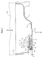
- FIG. 1 is a vertical sectional view of an oil pan of an engine (sectional view taken along line 1-1 in FIG. 3).
- FIG. 2 is a view showing an undersurface of the oil pan (view seen from the direction of
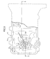
arrow 2 in FIG. 1). - FIG. 3 is a view showing a top surface of the oil pan (view seen from the direction of
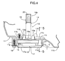
arrow 3 in FIG. 1). - FIG. 4 is an enlarged view of a main part in FIG. 1.
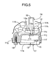
- FIG. 5 is a sectional view taken along line 5-5 in FIG. 4.
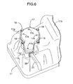
- FIG. 6 is a view seen from the direction of
arrow 6 in FIG. 2. - FIG. 7 is a view seen from the direction of
arrow 7 in FIG. 3. - An
oil pan 11 is mounted to a bottom surface of a cylinder block 10 (see FIG. 1) of an engine of an automobile. Theoil pan 11 is a vessel type member including amounting surface 11a with respect to thecylinder block 10 at a peripheral edge of an opening of its top surface. Anoil level sensor 12 for detecting an oil level in theoil pan 11 is provided at one end side in a longitudinal direction of theoil pan 11. - In the bottom portion of the
oil pan 11, alowest part 11b which is the lowest in height is provided at a central portion in the longitudinal direction. Asensor mounting part 11c is provided at a position which is adjacent to thelowest part 11b and is raised by one step higher. Thesensor mounting part 11c is thick as compared with the other parts of the bottom surface of theoil pan 11 including thelowest part 11b, and a circular sensor mounting opening 11d is formed in the center of thesensor mounting part 11c. Anoil drain hole 11e for draining the engine oil in theoil pan 11 is formed in the vicinity of the side opposite from thesensor mounting part 11c with thelowest part 11b therebetween. - On an undersurface of the
oil pan 11, anannular rib 11f is projectingly provided so as to surround a periphery of the sensor mounting opening 11d, andbosses 11g are formed at four spots of therib 11f. Threebosses 11h are projectingly provided on a top surface of theoil pan 11 to surround the periphery of the sensor mounting opening 11d. Further, on the top surface of theoil pan 11, anoil release groove 11i having a trapezoidal section is formed to cross the thicksensor mounting part 11c which surrounds the periphery of the sensor mounting opening 11d. The height of an upstream end of theoil release groove 11i, which communicates with the sensor mounting opening 11d, is lower than the height of anoil hole 19a of acover member 19 of asensing part 14. The height of a downstream end of theoil release groove 11i which opens toward thelowest part 11b of theoil pan 11 is lower than the bottom of the sensor mounting opening 11d. - The
oil level sensor 12 includes amounting part 13 which is formed into a hexagonal box shape in plane view, and thesensing part 14 having a shape of a tower extending upward from the center of themounting part 13. In a state in which the outer peripheral surfaces of threeprojections 13a projectingly provided on a top surface of themounting part 13 so as to surround thesensing part 14 are fitted in the sensor mounting opening 11d of theoil pan 11, threebolts 15 penetrating from below through themounting part 13 are threadedly fitted into the threebosses 11h surrounding the periphery of the sensor mounting opening 11d, whereby theoil level sensor 12 is fixed to theoil pan 11. At this time, aseal member 16 for preventing leakage of the engine oil is sandwiched between the undersurface of the outer peripheral portion of the sensor mounting opening 11d and the top surface of themounting part 13 of theoil level sensor 12. - A plate-
shaped cover plate 17 abuts on the lower end of theannular rib 11f projectingly provided on the undersurface of theoil pan 11, and is fixed thereto with fourbolts 18 which are threadedly fitted in thefourbosses 11g. Accordingly, themounting part 13 of theoil level sensor 12 is accommodated in arecessed part 11j surrounded by thesensor mounting part 11c and therib 11f of theoil pan 11, and is covered with thecover plate 17 from below. Fourwater draining holes 17a are formed in thecover plate 17. - The sensing
part 14 of theoil level sensor 12 includes ahollow cover member 19. Anoil hole 19a in a slit shape laterally longer (see FIG. 4) for communication with the engine oil in theoil pan 11 is formed at a lower end of thecover member 19. Anair hole 19b (see FIG. 4) for communication with air in theoil pan 11 is formed at an upper end of thecover member 19. Therefore, the oil level in thecover member 19 of thesensing part 14 moves up and down corresponding to the oil level in theoil pan 11. - A plate-shaped sensing element 20 (see FIG. 4) is disposed inside the
cover member 19 of thesensing part 14 of theoil level sensor 12. Thesensing element 20 is energized to generate heat so that thesensing element 20 has a temperature higher by, for example, 10°C than the oil temperature, and the time elapsing before the temperature decreases by, for example, 5°C is measured. When the oil level is high, heat radiation from thesensing element 20 to the engine oil is promoted, and the temperature drops fast. On the other hand, when the oil level is low, heat radiation from thesensing element 20 to the engine oil is suppressed and the temperature slowly decreases. With this mechanism, the oil level in theoil pan 11 can be detected. - A harness 21 (see FIG. 6) extending from the mounting
part 13 of theoil level sensor 12 penetrates through a grommet 22 (see FIG. 6) which is fitted in a notch of therib 11f of theoil pan 11, and is drawn to the outside. - As is obvious from FIGS. 1 and 4, the lowest part (the undersurface of the mounting part 13) of the
oil level sensor 12 is located at a position higher by a distance α with respect to the undersurface of thelowest part 11b of theoil pan 11; the mountingpart 13 of theoil level sensor 12, which is exposed from the undersurface of theoil pan 11, is housed in the recessedpart 11j, with its outer periphery surrounded by therib 11f; and the undersurface of the mountingpart 13 of theoil level sensor 12 is covered with thecover plate 17. With this arrangement, when the engine is directly placed on the floor surface, the weight of the engine can be prevented from directly acting on the mountingpart 13 of theoil level sensor 12, and at the time of colliding with a flying stone, riding on a curbstone, jacking up or the like in a state in which the engine is mounted on the vehicle body, the mountingpart 13 of theoil level sensor 12 can be protected from being damaged. - The undersurface of the
lowest part 11b of theoil pan 11 and the undersurface of thecover plate 17 are at the same height and are located on the same plane, and therefore, when the engine is directly placed on the floor surface, the weight of the engine are supported by the undersurface of thelowest part 11b of theoil pan 11 and the undersurface of thecover plate 17, thereby stabilizing the posture of the engine. - When the engine oil in the
oil pan 11 is drained from theoil drain hole 11e for replacement, the engine oil is likely to remain inside thesensor mounting opening 11d surrounded by the thicksensor mounting part 11c. If the remaining engine oil contains a foreign substance such as sludge, theoil hole 19a of thecover member 19 of thesensing part 14 is likely to be clogged with the foreign substance. However, according to this embodiment, theoil release groove 11i is formed on the thicksensor mounting part 11c which surrounds thesensor mounting opening 11d. Therefore, the engine oil remaining inside thesensor mounting opening 11d is caused to flow out to thelowest part 11b through theoil release groove 11i, and can be discharged out of theoil pan 11 from theoil drain hole 11e formed in the vicinity of thelowest part 11b. Particularly because theoil release groove 11i monotonously inclines downward from thesensor mounting opening 11d to thelowest part 11b, the foreign substance can be effectively discharged. - The embodiment of the present invention has been described in detail above, but various design changes can be made thereto without departing from the subj ect matter of the present invention.
- For example, in the embodiment, the
oil level sensor 12 which detects the level of the engine oil is described, but the present invention is applicable to any other oil sensors which detect the temperature or deterioration degree of engine oil. - Of a sensing part (14) and a mounting part (13) of an oil level sensor (12) mounted to a sensor mounting opening (11d) at a bottom portion of an oil pan (11) of an engine, an undersurface of the mounting part (13) exposed to the outside of the oil pan (11) is located above the lowest part (11b) of the oil pan (11) by a distance (α), and the mounting part (13) is disposed in a recessed part (11j) formed on an undersurface of the oil pan (11) and is covered with a cover plate (17). Therefore, the weight of the engine does not directly act on the mounting part (13) of the oil level sensor (12) when the engine is directly placed on a floor surface. Further, even in a state in which the engine is mounted on a vehicle body, the mounting part (13) of the oil level sensor (12) can be also effectively protected at the time of colliding with a flying stone, riding on a curbstone, jacking up or the like.
Claims (9)
- An oil sensor mounting structure in which an oil sensor which detects a parameter of engine oil is mounted to a sensor mounting opening provided at a bottom portion of an oil pan which is located below a cylinder block of an engine and stores the engine oil; and the oil sensor comprises a sensing part accommodated inside the oil pan, and a mounting part which is exposed to the outside of the oil pan,
wherein the mounting part of the oil sensor is covered with a cover. - An oil sensor mounting structure in which an oil sensor which detects a parameter of engine oil is mounted to a sensor mounting opening provided at a bottom portion of an oil pan which is located below a cylinder block of an engine and stores the engine oil; and the oil sensor comprises a sensing part accommodated inside the oil pan, and a mounting part which is exposed to the outside of the oil pan,
wherein the mounting part of the oil sensor is disposed in a recessed part which is formed on an undersurface of the oil pan. - The mounting structure of an oil sensor according to claim 2, wherein the recessed part surrounds a side portion in a mounting direction of the mounting part of the oil sensor over a substantially entire circumference.
- An oil sensor mounting structure in which an oil sensor which detects a parameter of engine oil is mounted to a sensor mounting opening provided at a bottom portion of an oil pan which is located below a cylinder block of an engine and stores the engine oil; and the oil sensor comprises a sensing part accommodated inside the oil pan, and a mounting part which is exposed to the outside of the oil pan,
wherein an undersurface of the mounting part of the oil sensor is located at a position higher than the lowest part of the oil pan. - An oil sensor mounting structure in which an oil sensor which detects a parameter of engine oil is mounted to a sensor mounting opening provided at a bottom portion of an oil pan which is located below a cylinder block of an engine and stores the engine oil; and the oil sensor comprises a sensing part accommodated inside the oil pan, and a mounting part which is exposed to the outside of the oil pan,
wherein an undersurface of the mounting part of the oil sensor is located at a position higher than the lowest part of the oil pan; and
wherein a rib is projectingly provided on an undersurface of the oil pan to surround a side portion in a mounting direction of the mounting part of the oil sensor over a substantially entire circumference. - The mounting structure of an oil sensor according to claim 5, wherein the mounting part of the oil sensor is covered with a cover.
- The mounting structure of an oil sensor according to claim 6, wherein an undersurface of the cover and an undersurface of the lowest part of the oil pan are substantially located on the same plane.
- The mounting structure of an oil sensor according to any one of claims 1 to 7, wherein an oil hole, into which engine oil flows, is provided in the vicinity of a lower end portion of the sensing part, the oil hole being located at a position lower than an upper edge of the sensor mounting part which surrounds the sensor mounting opening; and an oil release groove is formed in the sensor mounting part so that its upstream end communicates with the sensor mounting opening at a position lower than the oil hole, and its downstream end communicates with the bottom portion of the oil pan at a position lower than a lower end of the sensor mounting opening.
- The mounting structure of an oil sensor according to claim 8, wherein the oil release groove monotonously inclines downward from the upstream end on the sensor mounting opening side to the downstream end.
Priority Applications (1)
| Application Number | Priority Date | Filing Date | Title |
|---|---|---|---|
| EP11176729.9A EP2385368B1 (en) | 2005-09-09 | 2006-09-05 | Oil sensor mounting structure |
Applications Claiming Priority (2)
| Application Number | Priority Date | Filing Date | Title |
|---|---|---|---|
| JP2005261588A JP4512015B2 (en) | 2005-09-09 | 2005-09-09 | Oil sensor mounting structure |
| JP2005261589A JP4573737B2 (en) | 2005-09-09 | 2005-09-09 | Oil sensor mounting structure |
Related Child Applications (1)
| Application Number | Title | Priority Date | Filing Date |
|---|---|---|---|
| EP11176729.9 Division-Into | 2011-08-05 |
Publications (3)
| Publication Number | Publication Date |
|---|---|
| EP1762846A2 true EP1762846A2 (en) | 2007-03-14 |
| EP1762846A3 EP1762846A3 (en) | 2010-06-02 |
| EP1762846B1 EP1762846B1 (en) | 2012-08-01 |
Family
ID=37499489
Family Applications (2)
| Application Number | Title | Priority Date | Filing Date |
|---|---|---|---|
| EP11176729.9A Ceased EP2385368B1 (en) | 2005-09-09 | 2006-09-05 | Oil sensor mounting structure |
| EP06018577A Not-in-force EP1762846B1 (en) | 2005-09-09 | 2006-09-05 | Oil sensor mounting structure |
Family Applications Before (1)
| Application Number | Title | Priority Date | Filing Date |
|---|---|---|---|
| EP11176729.9A Ceased EP2385368B1 (en) | 2005-09-09 | 2006-09-05 | Oil sensor mounting structure |
Country Status (2)
| Country | Link |
|---|---|
| US (1) | US7263964B2 (en) |
| EP (2) | EP2385368B1 (en) |
Cited By (1)
| Publication number | Priority date | Publication date | Assignee | Title |
|---|---|---|---|---|
| CN108350774A (en) * | 2015-11-12 | 2018-07-31 | 五十铃自动车株式会社 | Oil disc device |
Families Citing this family (5)
| Publication number | Priority date | Publication date | Assignee | Title |
|---|---|---|---|---|
| JP4573808B2 (en) * | 2006-06-15 | 2010-11-04 | 本田技研工業株式会社 | Oil sensor arrangement structure in the engine |
| CN202133061U (en) * | 2008-11-26 | 2012-02-01 | 德尔福技术有限公司 | Refrigerant leakage detection system and refrigerant sensor assembly thereof |
| CN203962092U (en) * | 2013-12-19 | 2014-11-26 | 重庆隆鑫发动机有限公司 | Oil level detection construction package and sensor |
| US9512751B2 (en) * | 2014-09-22 | 2016-12-06 | Hyundai Motor Company | Device and method for reducing fuel dilution of diesel engine |
| KR20220096104A (en) * | 2020-12-30 | 2022-07-07 | 현대두산인프라코어(주) | Oil Level Sensor Cover and Engine having the same |
Citations (2)
| Publication number | Priority date | Publication date | Assignee | Title |
|---|---|---|---|---|
| JPS6075709A (en) | 1983-09-30 | 1985-04-30 | Yamaha Motor Co Ltd | Seizure preventive device of spark ignition engine |
| US5687687A (en) | 1995-06-07 | 1997-11-18 | Cummins Engine Company, Inc. | Oil level sensor system |
Family Cites Families (9)
| Publication number | Priority date | Publication date | Assignee | Title |
|---|---|---|---|---|
| US5097703A (en) * | 1984-11-30 | 1992-03-24 | Aisin Seiki Kabushiki Kaisha | Capacitive probe for use in a system for remotely measuring the level of fluids |
| US5196824A (en) * | 1988-11-29 | 1993-03-23 | Oil Monitoring Systems, Inc. | Float actuated liquid level monitoring apparatus |
| JP2731240B2 (en) * | 1989-05-25 | 1998-03-25 | 富士重工業株式会社 | Oil sensor |
| KR200170993Y1 (en) * | 1996-10-07 | 2000-04-01 | 정몽규 | Oil level sensor of oil pan |
| US6052896A (en) * | 1998-08-15 | 2000-04-25 | Navistar International Transportation Corp. | Method of installing an oil pan heater on an oil pan mounted on an engine block |
| US6791334B2 (en) * | 2001-02-22 | 2004-09-14 | Denso Corporation | Oil condition sensor and method for making the same |
| JP3724420B2 (en) | 2001-07-03 | 2005-12-07 | 株式会社デンソー | Oil detection device |
| US20030041659A1 (en) * | 2001-09-04 | 2003-03-06 | Detroit Diesel Corporation | Electrically conductive engine oil pan sensor mounting arrangement |
| US7043983B2 (en) * | 2003-12-15 | 2006-05-16 | Fling William F | Horizontal liquid level measuring device |
-
2006
- 2006-09-05 EP EP11176729.9A patent/EP2385368B1/en not_active Ceased
- 2006-09-05 EP EP06018577A patent/EP1762846B1/en not_active Not-in-force
- 2006-09-08 US US11/517,584 patent/US7263964B2/en not_active Expired - Fee Related
Patent Citations (2)
| Publication number | Priority date | Publication date | Assignee | Title |
|---|---|---|---|---|
| JPS6075709A (en) | 1983-09-30 | 1985-04-30 | Yamaha Motor Co Ltd | Seizure preventive device of spark ignition engine |
| US5687687A (en) | 1995-06-07 | 1997-11-18 | Cummins Engine Company, Inc. | Oil level sensor system |
Cited By (1)
| Publication number | Priority date | Publication date | Assignee | Title |
|---|---|---|---|---|
| CN108350774A (en) * | 2015-11-12 | 2018-07-31 | 五十铃自动车株式会社 | Oil disc device |
Also Published As
| Publication number | Publication date |
|---|---|
| EP1762846A3 (en) | 2010-06-02 |
| US20070057675A1 (en) | 2007-03-15 |
| EP1762846B1 (en) | 2012-08-01 |
| EP2385368B1 (en) | 2013-10-16 |
| US7263964B2 (en) | 2007-09-04 |
| EP2385368A1 (en) | 2011-11-09 |
Similar Documents
| Publication | Publication Date | Title |
|---|---|---|
| US8109148B2 (en) | Pressure compensation unit for use in a pressure sensor | |
| US8871084B2 (en) | Fluid filter comprising a protected liquid sensor | |
| US20110041594A1 (en) | Pressure compensation unit | |
| US20120152645A1 (en) | Water drain valve comprising an umbrella diaphragm | |
| EP1762846B1 (en) | Oil sensor mounting structure | |
| CA2651955A1 (en) | Oil sensor placement structure in engine | |
| US20080141779A1 (en) | Air-pressure sensor for side-impact detection | |
| US7981279B2 (en) | Oil filter with bypass valve | |
| JP4512015B2 (en) | Oil sensor mounting structure | |
| JP4573737B2 (en) | Oil sensor mounting structure | |
| EP1762847A3 (en) | Oil pan for automotive engines | |
| KR20160069720A (en) | Apparatus for detecting coolant lack of cooling system for vehicle | |
| US11813558B2 (en) | Atmospheric box | |
| CN220248170U (en) | Oil level sensor cover and engine including same | |
| JP3876249B2 (en) | Fuel injection valve seal structure | |
| US20210088401A1 (en) | Low-pressure sensor device and use of an inlet connector piece as a fluid inlet for a low-pressure sensor device | |
| US12117355B2 (en) | Sealing element for a pressure sensor assembly for a motor vehicle and pressure sensor assembly | |
| CN204827598U (en) | Engine oil level sensor's mounting structure | |
| JP2000185563A (en) | Engine fuel tank | |
| JP5364361B2 (en) | Water sub tank | |
| CN108431559A (en) | Liquid level sensor | |
| JP4708375B2 (en) | Oil sensor | |
| EP3406316B1 (en) | A filter for improving suction capability of a fuel pump | |
| JP2005030283A (en) | Strainer for oil filling port | |
| GB2555448A (en) | Fuel filter with water sensor, and sensor therefor |
Legal Events
| Date | Code | Title | Description |
|---|---|---|---|
| PUAI | Public reference made under article 153(3) epc to a published international application that has entered the european phase |
Free format text: ORIGINAL CODE: 0009012 |
|
| AK | Designated contracting states |
Kind code of ref document: A2 Designated state(s): AT BE BG CH CY CZ DE DK EE ES FI FR GB GR HU IE IS IT LI LT LU LV MC NL PL PT RO SE SI SK TR |
|
| AX | Request for extension of the european patent |
Extension state: AL BA HR MK YU |
|
| PUAL | Search report despatched |
Free format text: ORIGINAL CODE: 0009013 |
|
| AK | Designated contracting states |
Kind code of ref document: A3 Designated state(s): AT BE BG CH CY CZ DE DK EE ES FI FR GB GR HU IE IS IT LI LT LU LV MC NL PL PT RO SE SI SK TR |
|
| AX | Request for extension of the european patent |
Extension state: AL BA HR MK RS |
|
| 17P | Request for examination filed |
Effective date: 20101129 |
|
| AKX | Designation fees paid |
Designated state(s): DE GB |
|
| 17Q | First examination report despatched |
Effective date: 20110404 |
|
| GRAP | Despatch of communication of intention to grant a patent |
Free format text: ORIGINAL CODE: EPIDOSNIGR1 |
|
| GRAS | Grant fee paid |
Free format text: ORIGINAL CODE: EPIDOSNIGR3 |
|
| GRAA | (expected) grant |
Free format text: ORIGINAL CODE: 0009210 |
|
| AK | Designated contracting states |
Kind code of ref document: B1 Designated state(s): DE GB |
|
| REG | Reference to a national code |
Ref country code: GB Ref legal event code: FG4D |
|
| REG | Reference to a national code |
Ref country code: DE Ref legal event code: R096 Ref document number: 602006031030 Country of ref document: DE Effective date: 20120927 |
|
| PLBE | No opposition filed within time limit |
Free format text: ORIGINAL CODE: 0009261 |
|
| STAA | Information on the status of an ep patent application or granted ep patent |
Free format text: STATUS: NO OPPOSITION FILED WITHIN TIME LIMIT |
|
| 26N | No opposition filed |
Effective date: 20130503 |
|
| GBPC | Gb: european patent ceased through non-payment of renewal fee |
Effective date: 20121101 |
|
| REG | Reference to a national code |
Ref country code: DE Ref legal event code: R097 Ref document number: 602006031030 Country of ref document: DE Effective date: 20130503 |
|
| PG25 | Lapsed in a contracting state [announced via postgrant information from national office to epo] |
Ref country code: GB Free format text: LAPSE BECAUSE OF NON-PAYMENT OF DUE FEES Effective date: 20121101 |
|
| REG | Reference to a national code |
Ref country code: DE Ref legal event code: R084 Ref document number: 602006031030 Country of ref document: DE Effective date: 20140430 |
|
| PGFP | Annual fee paid to national office [announced via postgrant information from national office to epo] |
Ref country code: DE Payment date: 20220609 Year of fee payment: 17 |
|
| REG | Reference to a national code |
Ref country code: DE Ref legal event code: R119 Ref document number: 602006031030 Country of ref document: DE |
|
| PG25 | Lapsed in a contracting state [announced via postgrant information from national office to epo] |
Ref country code: DE Free format text: LAPSE BECAUSE OF NON-PAYMENT OF DUE FEES Effective date: 20240403 |