EP1762743B1 - Snap in ABS exciter ring - Google Patents
Snap in ABS exciter ring Download PDFInfo
- Publication number
- EP1762743B1 EP1762743B1 EP06017574A EP06017574A EP1762743B1 EP 1762743 B1 EP1762743 B1 EP 1762743B1 EP 06017574 A EP06017574 A EP 06017574A EP 06017574 A EP06017574 A EP 06017574A EP 1762743 B1 EP1762743 B1 EP 1762743B1
- Authority
- EP
- European Patent Office
- Prior art keywords
- rotor
- exciter ring
- cylindrically shaped
- interior surface
- tangs
- Prior art date
- Legal status (The legal status is an assumption and is not a legal conclusion. Google has not performed a legal analysis and makes no representation as to the accuracy of the status listed.)
- Not-in-force
Links
- 239000011324 bead Substances 0.000 claims description 21
- 238000007373 indentation Methods 0.000 claims description 13
- 238000005260 corrosion Methods 0.000 claims description 7
- 230000007797 corrosion Effects 0.000 claims description 7
- 239000000463 material Substances 0.000 claims description 7
- 238000004519 manufacturing process Methods 0.000 claims description 5
- 238000005266 casting Methods 0.000 claims description 4
- 230000014759 maintenance of location Effects 0.000 claims description 3
- 238000000034 method Methods 0.000 claims description 3
- 229910001018 Cast iron Inorganic materials 0.000 claims 6
- 238000007493 shaping process Methods 0.000 claims 1
- 230000007246 mechanism Effects 0.000 abstract 1
- 229910001060 Gray iron Inorganic materials 0.000 description 4
- 229910001209 Low-carbon steel Inorganic materials 0.000 description 3
- XEEYBQQBJWHFJM-UHFFFAOYSA-N Iron Chemical compound [Fe] XEEYBQQBJWHFJM-UHFFFAOYSA-N 0.000 description 2
- 230000004048 modification Effects 0.000 description 2
- 238000012986 modification Methods 0.000 description 2
- XLYOFNOQVPJJNP-UHFFFAOYSA-N water Substances O XLYOFNOQVPJJNP-UHFFFAOYSA-N 0.000 description 2
- 230000002730 additional effect Effects 0.000 description 1
- 230000000712 assembly Effects 0.000 description 1
- 238000000429 assembly Methods 0.000 description 1
- 239000002131 composite material Substances 0.000 description 1
- 238000001514 detection method Methods 0.000 description 1
- 230000000694 effects Effects 0.000 description 1
- 230000004907 flux Effects 0.000 description 1
- 238000010438 heat treatment Methods 0.000 description 1
- 238000009434 installation Methods 0.000 description 1
- 229910052742 iron Inorganic materials 0.000 description 1
- 230000001788 irregular Effects 0.000 description 1
- 230000013011 mating Effects 0.000 description 1
- 230000000717 retained effect Effects 0.000 description 1
- 150000003839 salts Chemical class 0.000 description 1
- 239000007921 spray Substances 0.000 description 1
- 230000001052 transient effect Effects 0.000 description 1
Images




Classifications
-
- F—MECHANICAL ENGINEERING; LIGHTING; HEATING; WEAPONS; BLASTING
- F16—ENGINEERING ELEMENTS AND UNITS; GENERAL MEASURES FOR PRODUCING AND MAINTAINING EFFECTIVE FUNCTIONING OF MACHINES OR INSTALLATIONS; THERMAL INSULATION IN GENERAL
- F16D—COUPLINGS FOR TRANSMITTING ROTATION; CLUTCHES; BRAKES
- F16D65/00—Parts or details
- F16D65/02—Braking members; Mounting thereof
- F16D65/12—Discs; Drums for disc brakes
-
- B—PERFORMING OPERATIONS; TRANSPORTING
- B60—VEHICLES IN GENERAL
- B60T—VEHICLE BRAKE CONTROL SYSTEMS OR PARTS THEREOF; BRAKE CONTROL SYSTEMS OR PARTS THEREOF, IN GENERAL; ARRANGEMENT OF BRAKING ELEMENTS ON VEHICLES IN GENERAL; PORTABLE DEVICES FOR PREVENTING UNWANTED MOVEMENT OF VEHICLES; VEHICLE MODIFICATIONS TO FACILITATE COOLING OF BRAKES
- B60T8/00—Arrangements for adjusting wheel-braking force to meet varying vehicular or ground-surface conditions, e.g. limiting or varying distribution of braking force
- B60T8/32—Arrangements for adjusting wheel-braking force to meet varying vehicular or ground-surface conditions, e.g. limiting or varying distribution of braking force responsive to a speed condition, e.g. acceleration or deceleration
- B60T8/321—Arrangements for adjusting wheel-braking force to meet varying vehicular or ground-surface conditions, e.g. limiting or varying distribution of braking force responsive to a speed condition, e.g. acceleration or deceleration deceleration
- B60T8/329—Systems characterised by their speed sensor arrangements
-
- F—MECHANICAL ENGINEERING; LIGHTING; HEATING; WEAPONS; BLASTING
- F16—ENGINEERING ELEMENTS AND UNITS; GENERAL MEASURES FOR PRODUCING AND MAINTAINING EFFECTIVE FUNCTIONING OF MACHINES OR INSTALLATIONS; THERMAL INSULATION IN GENERAL
- F16D—COUPLINGS FOR TRANSMITTING ROTATION; CLUTCHES; BRAKES
- F16D65/00—Parts or details
- F16D65/02—Braking members; Mounting thereof
- F16D65/12—Discs; Drums for disc brakes
- F16D65/123—Discs; Drums for disc brakes comprising an annular disc secured to a hub member; Discs characterised by means for mounting
-
- G—PHYSICS
- G01—MEASURING; TESTING
- G01P—MEASURING LINEAR OR ANGULAR SPEED, ACCELERATION, DECELERATION, OR SHOCK; INDICATING PRESENCE, ABSENCE, OR DIRECTION, OF MOVEMENT
- G01P3/00—Measuring linear or angular speed; Measuring differences of linear or angular speeds
- G01P3/42—Devices characterised by the use of electric or magnetic means
- G01P3/44—Devices characterised by the use of electric or magnetic means for measuring angular speed
- G01P3/48—Devices characterised by the use of electric or magnetic means for measuring angular speed by measuring frequency of generated current or voltage
- G01P3/481—Devices characterised by the use of electric or magnetic means for measuring angular speed by measuring frequency of generated current or voltage of pulse signals
- G01P3/488—Devices characterised by the use of electric or magnetic means for measuring angular speed by measuring frequency of generated current or voltage of pulse signals delivered by variable reluctance detectors
-
- F—MECHANICAL ENGINEERING; LIGHTING; HEATING; WEAPONS; BLASTING
- F16—ENGINEERING ELEMENTS AND UNITS; GENERAL MEASURES FOR PRODUCING AND MAINTAINING EFFECTIVE FUNCTIONING OF MACHINES OR INSTALLATIONS; THERMAL INSULATION IN GENERAL
- F16D—COUPLINGS FOR TRANSMITTING ROTATION; CLUTCHES; BRAKES
- F16D65/00—Parts or details
- F16D65/02—Braking members; Mounting thereof
- F16D2065/13—Parts or details of discs or drums
- F16D2065/134—Connection
- F16D2065/1356—Connection interlocking
-
- F—MECHANICAL ENGINEERING; LIGHTING; HEATING; WEAPONS; BLASTING
- F16—ENGINEERING ELEMENTS AND UNITS; GENERAL MEASURES FOR PRODUCING AND MAINTAINING EFFECTIVE FUNCTIONING OF MACHINES OR INSTALLATIONS; THERMAL INSULATION IN GENERAL
- F16D—COUPLINGS FOR TRANSMITTING ROTATION; CLUTCHES; BRAKES
- F16D65/00—Parts or details
- F16D65/02—Braking members; Mounting thereof
- F16D2065/13—Parts or details of discs or drums
- F16D2065/134—Connection
- F16D2065/1392—Connection elements
Definitions
- the invention relates to anti-lock brake systems for motor vehicles and more particularly to an exciter ring and disc brake rotor assembly which allows snap in fitting and retention of the exciter ring on the disc brake rotor.
- Disc brake rotors have generally been made from relatively inexpensive gray iron castings. Gray iron is, however; highly susceptible to corrosive attack, particularly in the operating environment of vehicles where brake components are open to the air, subject to substantial transient heating and exposed to water and salt water spray. In regular use, the working surfaces of the discs are rubbed clean by contact with the disc pads, which are typically made of a composite material and which rub off corroded areas. However, other areas of the brake discs are not swept by the brake pads and are not regularly cleaned. Prior to anti-lock braking systems, such concerns were not paramount with brakes which were frequently in use, since the rotor is a regularly replaced part and the remaining areas subject to attack were not critical.
- the exciter ring is a cylindrical section of the rotor having a common axis of rotation with the rotor. A plurality of teeth is formed in a ring, which is flat in the plane of rotation of the rotor to pass closely by a stationary sensor.
- One type of sensor used is a variable reluctance sensor which generates an electrical pulse train as a function of the varying magnetic flux leakage between the sensor head and the exciter ring.
- the frequency of the resulting electrical pulse train indicates the rotational speed of the wheel on which the rotor is mounted.
- the generation of clean pulse train is greatly aided by having teeth of uniform shape, size and spacing. Where the ring is cast as one piece with the rotor, corrosion of the rotor can compromise all of these factors, resulting in difficulty in detecting the passage of teeth and gaps and causing generation of an irregular pulse train.
- Exciter rings are made of low carbon steel which has a different thermal coefficient of expansion than does iron.
- the difference in coefficients of expansion in the materials used for the ring and the hub or rotor causes more problems in disc brake systems than in drum systems since more heat is transferred by a rotor to a ring than by a hub to a ring and thus an exciter ring and rotor vary more in size in relation to each other than do an exciter ring and a hub.
- the DE 44 02 959 A1 shows an apparatus for pulse generation, in particular the detection of the rotation frequency or direction of rotation comprising a sensor and an exciter ring adapted for being fixed on an disc brake rotor.
- the rotor comprises a number of protrusions to incorporate the exciter ring and to fix the exciter ring in a radial direction.
- the exciter ring comprises flexible tongs to fix the exciter ring within a slot in the disc brake rotor in an axial direction.
- the DE 101 45 947 C1 shows a disc brake rotor comprising an exciter ring, wherein the exciter ring is fixed on the disc brake rotor in axial direction by protrusions of the disc brake rotor, and is fixed by a snap ring in an axial direction.
- the exciter ring fixed in the brake rotor shows an intentional clearance.
- disc brake rotor assemblies according to claims 1 and 2, and the corresponding methods of their fabrications respectively, according to claims 4 and 5.
- Exciter rings in accordance with the invention are readily fabricated in different sizes to accommodate rotors of differing sizes. No loose fasteners are required for installation.
- Fig. 1 is a perspective view of a rotor/exciter ring assembly in accordance with the invention.
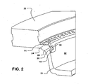
- Fig. 2 is a perspective view in partial cutaway illustrating mating of the exciter ring to the disc brake rotor in accordance with a first of two preferred embodiments of the invention.
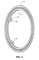
- Fig. 3 is a perspective view of an exciter ring in accordance with the first embodiment of the invention.
- Fig. 4 is a side elevation of the exciter ring of Fig. 3 .
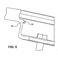
- Fig. 5 is a section view of a rotor constructed in accordance with the first embodiment.
- Fig. 6 is a cutaway view of rotor/exciter ring assembly in accordance with a second embodiment of the invention.
- Fig. 7 is a cutaway view of the rotor of Fig. 6 .
- Fig. 8 is a perspective view of the exciter ring for the second embodiment.
- Fig. 9 is a side elevation of the exciter ring of Fig. 8 .
- Fig. 1 an assembly 10 of a rotor 12 and an exciter ring 14 for a disc brake is shown.
- Exciter ring 14 is situated in a recess 16 in rotor 12, flat along one side of the ring against a shelf 24 (see Fig. 2 ). Shelf 24 is formed in rotor 12 during casting.
- Five tangs 18 are shown extending from an inner circumference 17 (see Fig. 3 ) of exciter ring 14. The number of tangs may be varied.
- the rings are preferably set at an oblique angle of 90 to 110 degrees with respect to the plane of the ring, and engage with rotor 12.
- Rotor 12 is a gray iron casting. Rotor 12 provides a wearable surface 22 which pads of the disc brake close on and wear against.
- Exciter ring 14, in both embodiments, is a stamped piece of mild low carbon steel, snap fit by tangs 18 onto the rotor and retained in position by the tangs.
- Exciter ring 14 is set as a recess 20 in rotor 12 centered within wearable surface 22.
- FIG. 2 details of exciter ring 14 and rotor 12 relating to capture between the elements are illustrated.
- exciter ring 14 is held along one major side to a shelf 24.
- One of tangs 18 is seen extending from the inner circumference 17 of exciter ring 14 into a deeper recess 20 in rotor 12. Tang 18 abuts along one side the inner cylindrical surface 21 of the deeper recess 20. Extending radially inwardly from the cylindrical surface 21 into recess 20 is a bead 26. Tang 18 operates as a catch, its sides defining an aperture 30 parallel to the interior surface forming recess 21.
- Tang 18 is captured on a bead 26 upon aligning the aperture 30 with the bead 26, holding the exciter ring 14 in place on rotor 12. Capture is assisted by the profile of bead 26, which has a bevel 28 facing the direction from which tang 18 is fitted into the recess 20. Beveled faces 57 are also applied to leading edges of the tangs 18. Upon introduction of the ring 14 into recess 16 each tang 18 is rotated into alignment with a bead 26 in the deeper recess 21. As ring 14 is moved axially into rotor 12 tangs 18 encounter the beveled surfaces 28 of the trapezoidally shaped beads 26 and ride up and over the beads before snapping down the far edge of the bead. A trapezoidal shape is not required. Only some sort of allowance between the ring and rotor is required. Beads 26 may be seen to not be a continuous ring, but as isolated raised points. This configuration serves to keep ring 14 from clocking.
- This first embodiment of the invention produces highly secure attachment between tang and rotor, but requires modification of molds in which rotors are cast to produce the beads 26.
- indentations 34 may be machined into the cylindrical interior surface 21 of rotors 12.
- Exciter rings 14 are then modified to attach to the indentations 34, as best seen in Fig. 7 .
- Indentations 34 are circumferentially distributed around the cylindrical surface 21.
- tangs 18 are modified to incorporate radially outwardly oriented projections 19 which are sized to fit into indentations 34. Projections 19 have a base inside tang 18 and extend outwardly toward the main body of exciter ring 18.
- Projections 19 can be seen to be partially punched out of the tangs, leaving an opening into which the projections can be pushed. Since the tangs 18 lead introduction of an exciter ring 14 to a rotor 12, the projections flatten into the openings in the tangs 18 as the ring is pushed into position on rotor 12.
- the projections 19 are, in effect, torsion springs which snap out along the trailing edge into indentations 34.
- the first embodiment of the invention emphasizes a secure attachment of the exciter ring 14 to a rotor 12 to minimize any prospect of clocking of the ring.
- the second embodiment of the invention costs less to produce than the first.
Landscapes
- Engineering & Computer Science (AREA)
- General Engineering & Computer Science (AREA)
- Mechanical Engineering (AREA)
- Transportation (AREA)
- Physics & Mathematics (AREA)
- General Physics & Mathematics (AREA)
- Braking Arrangements (AREA)
- Pharmaceuticals Containing Other Organic And Inorganic Compounds (AREA)
- Standing Axle, Rod, Or Tube Structures Coupled By Welding, Adhesion, Or Deposition (AREA)
- Pens And Brushes (AREA)
Abstract
Description
- The invention relates to anti-lock brake systems for motor vehicles and more particularly to an exciter ring and disc brake rotor assembly which allows snap in fitting and retention of the exciter ring on the disc brake rotor.
- Brake units for motor vehicles should provide smooth braking with reasonable service life. In some applications this need has been met with disc brakes. The cost effectiveness of disc brake systems depends in part on making the components out of easily worked, inexpensive material. Disc brake rotors have generally been made from relatively inexpensive gray iron castings. Gray iron is, however; highly susceptible to corrosive attack, particularly in the operating environment of vehicles where brake components are open to the air, subject to substantial transient heating and exposed to water and salt water spray. In regular use, the working surfaces of the discs are rubbed clean by contact with the disc pads, which are typically made of a composite material and which rub off corroded areas. However, other areas of the brake discs are not swept by the brake pads and are not regularly cleaned. Prior to anti-lock braking systems, such concerns were not paramount with brakes which were frequently in use, since the rotor is a regularly replaced part and the remaining areas subject to attack were not critical.
- With the advent of anti-lock braking systems (ABS) other sections of the disc brake rotor take on importance, particularly the anti-lock brake system exciter ring. The exciter ring is a cylindrical section of the rotor having a common axis of rotation with the rotor. A plurality of teeth is formed in a ring, which is flat in the plane of rotation of the rotor to pass closely by a stationary sensor. One type of sensor used is a variable reluctance sensor which generates an electrical pulse train as a function of the varying magnetic flux leakage between the sensor head and the exciter ring.
- In this system the frequency of the resulting electrical pulse train indicates the rotational speed of the wheel on which the rotor is mounted. The generation of clean pulse train is greatly aided by having teeth of uniform shape, size and spacing. Where the ring is cast as one piece with the rotor, corrosion of the rotor can compromise all of these factors, resulting in difficulty in detecting the passage of teeth and gaps and causing generation of an irregular pulse train.
- The problem of corrosion of exciter rings for anti-lock brake systems is not limited to disc brake systems, but is also an issue with drum brakes. In drum brakes the exciter ring has not been an integral part of the drum, but rather has been a separate part, press fitted on the end of a wheel hub. Press fitted parts can readily be made of material more corrosion resistant than gray iron, such as a mild low carbon steel. However, the press fitting of rings onto disc rotors has proven less successful than it has for hubs using drum brakes. The difficulty stems from the fact that in disc brake systems the exciter ring is in direct contact with the rotor, which is part of the active brake assembly, whereas the axle hub using drum brakes is not a brake component. On drum systems less heat is transferred from the hub which carries the exciter ring than is transferred in disc systems from the rotor to an exciter ring. Exciter rings are made of low carbon steel which has a different thermal coefficient of expansion than does iron. The difference in coefficients of expansion in the materials used for the ring and the hub or rotor causes more problems in disc brake systems than in drum systems since more heat is transferred by a rotor to a ring than by a hub to a ring and thus an exciter ring and rotor vary more in size in relation to each other than do an exciter ring and a hub. An exciter ring which loses its tight fit with a rotor can begin to clock (i.e., the ring rotates elative to the rotor). If a ring rotates on a rotor, the ring will not reflect actual wheel rotational velocity. This affects ABS operation. Such a ring could also "pop" off.
TheDE 44 02 959 A1 shows an apparatus for pulse generation, in particular the detection of the rotation frequency or direction of rotation comprising a sensor and an exciter ring adapted for being fixed on an disc brake rotor. For fixing the exciter ring, the rotor comprises a number of protrusions to incorporate the exciter ring and to fix the exciter ring in a radial direction. The exciter ring comprises flexible tongs to fix the exciter ring within a slot in the disc brake rotor in an axial direction.
TheDE 101 45 947 C1 shows a disc brake rotor comprising an exciter ring, wherein the exciter ring is fixed on the disc brake rotor in axial direction by protrusions of the disc brake rotor, and is fixed by a snap ring in an axial direction. To compensate for different expansions of the brake rotor and the exciter ring caused by different temperatures, the exciter ring fixed in the brake rotor shows an intentional clearance. - According to the invention there is provided disc brake rotor assemblies according to claims 1 and 2, and the corresponding methods of their fabrications respectively, according to claims 4 and 5.
- Exciter rings in accordance with the invention are readily fabricated in different sizes to accommodate rotors of differing sizes. No loose fasteners are required for installation.
- Additional effects, features and advantages will be apparent in the written description that follows.
- The novel features believed characteristic of the invention are set forth in the appended claims. The invention itself however, as well as a preferred mode of use, further objects and advantages thereof, will best be understood by reference to the following detailed description of an illustrative embodiment when read in conjunction with the accompanying drawings, wherein:
-
Fig. 1 is a perspective view of a rotor/exciter ring assembly in accordance with the invention. -
Fig. 2 is a perspective view in partial cutaway illustrating mating of the exciter ring to the disc brake rotor in accordance with a first of two preferred embodiments of the invention. -
Fig. 3 is a perspective view of an exciter ring in accordance with the first embodiment of the invention. -
Fig. 4 is a side elevation of the exciter ring ofFig. 3 . -
Fig. 5 is a section view of a rotor constructed in accordance with the first embodiment. -
Fig. 6 is a cutaway view of rotor/exciter ring assembly in accordance with a second embodiment of the invention. -
Fig. 7 is a cutaway view of the rotor ofFig. 6 . -
Fig. 8 is a perspective view of the exciter ring for the second embodiment. -
Fig. 9 is a side elevation of the exciter ring ofFig. 8 . - Referring now to the figures and in particular to
Fig. 1 , anassembly 10 of arotor 12 and anexciter ring 14 for a disc brake is shown. Exciterring 14 is situated in arecess 16 inrotor 12, flat along one side of the ring against a shelf 24 (seeFig. 2 ).Shelf 24 is formed inrotor 12 during casting. Fivetangs 18 are shown extending from an inner circumference 17 (seeFig. 3 ) ofexciter ring 14. The number of tangs may be varied. The rings are preferably set at an oblique angle of 90 to 110 degrees with respect to the plane of the ring, and engage withrotor 12. The precise configuration oftangs 18 and the manner of attachment ofring 14 torotor 12 also varies between the two preferred embodiments.Rotor 12 is a gray iron casting.Rotor 12 provides awearable surface 22 which pads of the disc brake close on and wear against. Exciterring 14, in both embodiments, is a stamped piece of mild low carbon steel, snap fit bytangs 18 onto the rotor and retained in position by the tangs.Exciter ring 14 is set as arecess 20 inrotor 12 centered withinwearable surface 22. - Referring to
Figs. 2-5 , details ofexciter ring 14 androtor 12 relating to capture between the elements are illustrated. InFig. 2 ,exciter ring 14 is held along one major side to ashelf 24. One oftangs 18 is seen extending from theinner circumference 17 ofexciter ring 14 into adeeper recess 20 inrotor 12.Tang 18 abuts along one side the innercylindrical surface 21 of thedeeper recess 20. Extending radially inwardly from thecylindrical surface 21 intorecess 20 is abead 26.Tang 18 operates as a catch, its sides defining anaperture 30 parallel to the interiorsurface forming recess 21.Tang 18 is captured on abead 26 upon aligning theaperture 30 with thebead 26, holding theexciter ring 14 in place onrotor 12. Capture is assisted by the profile ofbead 26, which has abevel 28 facing the direction from whichtang 18 is fitted into therecess 20. Beveled faces 57 are also applied to leading edges of thetangs 18. Upon introduction of thering 14 intorecess 16 eachtang 18 is rotated into alignment with abead 26 in thedeeper recess 21. Asring 14 is moved axially intorotor 12tangs 18 encounter thebeveled surfaces 28 of the trapezoidally shapedbeads 26 and ride up and over the beads before snapping down the far edge of the bead. A trapezoidal shape is not required. Only some sort of allowance between the ring and rotor is required.Beads 26 may be seen to not be a continuous ring, but as isolated raised points. This configuration serves to keepring 14 from clocking. - This first embodiment of the invention produces highly secure attachment between tang and rotor, but requires modification of molds in which rotors are cast to produce the
beads 26. - Referring to
Figs. 6-9 , a second embodiment of the invention is illustrated. To avoid the expense of modifying molds to providebeads 26 onrotor 12 surfaces,indentations 34 may be machined into the cylindricalinterior surface 21 ofrotors 12. Exciter rings 14 are then modified to attach to theindentations 34, as best seen inFig. 7 .Indentations 34 are circumferentially distributed around thecylindrical surface 21. As seen inFigs. 8 and9 , tangs 18 are modified to incorporate radially outwardly orientedprojections 19 which are sized to fit intoindentations 34.Projections 19 have a base insidetang 18 and extend outwardly toward the main body ofexciter ring 18.Projections 19 can be seen to be partially punched out of the tangs, leaving an opening into which the projections can be pushed. Since thetangs 18 lead introduction of anexciter ring 14 to arotor 12, the projections flatten into the openings in thetangs 18 as the ring is pushed into position onrotor 12. Theprojections 19 are, in effect, torsion springs which snap out along the trailing edge intoindentations 34. - The first embodiment of the invention emphasizes a secure attachment of the
exciter ring 14 to arotor 12 to minimize any prospect of clocking of the ring. The second embodiment of the invention costs less to produce than the first. - While the invention is shown in only two of its forms, it is not thus limited but is susceptible to various changes and modifications without departing from the scope of the invention.
Claims (7)
- A disc brake rotor assembly comprising:a cast iron rotor(12) for rotation about an axis, the cast iron rotor having a cylindrically shaped interior surface; andan exciter ring(14) made of a corrosion resistant material and flattened to define opposite major surfaces and having tangs (18) arranged circumferentially with respect to one another and extending from one major surface into engagement with the cylindrically shaped interior surfaces of the cast iron rotor(12)characterized in that
the cylindrically shaped interior surface is continuous and wherein it comprises a plurality of indentations(34), and the plurality of indentations(34) being coplanar and circumferentially distributed about the cylindrically shaped interior surface;
and the exciter ring is being inserted in an orientation to bring each of the plurality of tangs(18) into alignment with a corresponding one of the plurality of indentations(34);
and a retaining element (19) is projecting outwardly from each tang(18) into engagement with the adjacent indentation and holds the exciter ring(14) on place on rotor(12) and keeps the exciter ring(14) from clocking. - A disc brake rotor assembly comprising:a cast iron rotor (12) for rotation about an axis, the cast iron rotor having a cylindrically shaped interior surface; andan exciter ring(14) made of a corrosion resistant material and flattened to define opposite major surfaces and having tangs(18) arranged circumferentially with respect to one another andextending from one major surface into engagement with the cylindrically shaped interior surface of the cast iron rotor (12), anda plurality of beads(26) is extending away from the cylindrically shaped interior surface, the plurality ofbeads(26) being coplanar and circumferentially distributed as isolated points about the cylindrically shaped interior surface;and the exciter ring(14) is being inserted in an orientation aligning each of the plurality of tangs(18) with a corresponding one of the plurality of beads(26);characterized in that an opening(30) in each tang(18) into which one bead(26) is flitted for retaining the exciter ring(14) is in place and holds the exciter ring(14) in place on the rotor(12) and keeps the exciter ring(14) from clocking.
- A disc brake rotor assembly as set forth in claim 2, further comprising:the beads(26) having a beveled surface(57) facing a direction from which the tangs(18) are introduced.
- A method of fabricating a disc brake rotor assembly, the method comprising the steps of:providing a rotor(12) having a cylindrically shaped interior surface;stamping an exciter ring(14) made of a material corrosion resistant when compared to the rotor(12) and flattened to define opposite major surfaces and provided with circumferentially arranged tangs(18) extending from one of the major sides of the exciter ring; andfitting the exciter ring(14) onto the rotor(12) with the tangs(18) extending into an interior of the rotor(12) defined by the cylindrically shaped interior surface and into contact with the cylindrically shaped interior surface for retention of the exciter ring on the rotor(12); characterized in that including a plurality of indentations(34) in the cylindrically shaped interior surface which is continuous the plurality of indentations(34) being coplanar and circumferentially distributed about the cylindrically shaped interior surface;positioning the exciter ring(14) to position the tangs(18) into contact with the cylindrically shaped interior surface with each of the plurality of tangs(18) aligned on a corresponding one of the plurality of indentations(34); andproviding a cooperating retaining element(19) projecting outwardly from each tang(18) for engagement with its adjacent indentation and for holding the exciter ring(14) in place on the rotor(12) and for keeping the exciter ruing(14) from clocking.
- A method of fabricating a disc brake rotor assembly comprising the steps of:providing a rotor(12) having a cylindrically shaped interior surface;stamping an exciter ring(14) made of a material corrosion resistant when compared to the rotor(12) and flattened to define opposite major surfaces and provided with circumferentially arranged tangs(18) extending from one of the major sides of the exciter ring; andfitting the exciter ring(14) onto the rotor(12) with the tangs(18) extending into an interior of the rotor(12) defined by the cylindrically shaped interior surface and into contact with the cylindrically shaped interior surface for retention of the exciter ring on the rotor(12)casting the rotor(12) in a mold defining a plurality of beads(26) on the cylindrically shaped interior surface, the plurality of beads(26) being coplanar and circumferentially distributed as isolated points about the cylindrically shaped interior surface;inserting the exciter ring(14) rotated to bring each of the plurality of tangs(18) into alignment with a different one of the plurality of beads(26);characterized by providing an opening(30) in each tang(18); andfitting each opening(30) over a corresponding one of the plurality of beads(26) to retain the exciter ring(14) in place on the rotor(12) and keeping the exciter ring(14) from clocking.
- A method of fabricating a disc brake rotor assembly as set forth in claim 5, further comprising the steps of:shaping the bead(26) to have a bevel(57) disposed for displacing the tangs(18) upwardly while the tang(18) is initially moved over the bead(26).
- A method of fabricating a disc brake rotor assembly as set forth in claim 4, the method comprising the further steps of providing bevelled faces (57) to the leading edges of the tangs (18).
Applications Claiming Priority (1)
| Application Number | Priority Date | Filing Date | Title |
|---|---|---|---|
| US11/220,435 US7487862B2 (en) | 2005-09-07 | 2005-09-07 | Snap in ABS exciter ring |
Publications (3)
| Publication Number | Publication Date |
|---|---|
| EP1762743A2 EP1762743A2 (en) | 2007-03-14 |
| EP1762743A3 EP1762743A3 (en) | 2008-02-13 |
| EP1762743B1 true EP1762743B1 (en) | 2010-04-14 |
Family
ID=37440686
Family Applications (1)
| Application Number | Title | Priority Date | Filing Date |
|---|---|---|---|
| EP06017574A Not-in-force EP1762743B1 (en) | 2005-09-07 | 2006-08-23 | Snap in ABS exciter ring |
Country Status (6)
| Country | Link |
|---|---|
| US (1) | US7487862B2 (en) |
| EP (1) | EP1762743B1 (en) |
| AT (1) | ATE464489T1 (en) |
| CA (1) | CA2557114A1 (en) |
| DE (1) | DE602006013557D1 (en) |
| MX (1) | MXPA06009568A (en) |
Cited By (2)
| Publication number | Priority date | Publication date | Assignee | Title |
|---|---|---|---|---|
| WO2014132202A1 (en) | 2013-02-26 | 2014-09-04 | Piaggio & C. S.P.A. | Disc brake disc and phonic wheel |
| EP4129784A1 (en) | 2021-08-03 | 2023-02-08 | Brembo North America, Inc. | Anti-lock sensor ring, disk brake band and assembly |
Families Citing this family (17)
| Publication number | Priority date | Publication date | Assignee | Title |
|---|---|---|---|---|
| USD624472S1 (en) | 2007-10-04 | 2010-09-28 | Schwäbische Hüttenwerke Automotive GmbH & Co. KG | Inner side portion of a brake rotor |
| US7980367B2 (en) * | 2008-01-30 | 2011-07-19 | Walther Engineering And Manufacturing Company, Inc. | Disc brake assembly with tone ring |
| DE102008017360B3 (en) * | 2008-04-04 | 2009-07-30 | Knorr-Bremse Systeme für Nutzfahrzeuge GmbH | Brake disk arrangement for wheel hub of commercial vehicle, has pulse wheel comprising connecting lug for axial and non-rotating fixing of pulse wheel, and connecting part engaged behind support elements |
| US8020676B2 (en) * | 2008-08-08 | 2011-09-20 | International Truck Intellectual Property Company, Llc | Tone ring for an anti-lock brake system |
| CN105393016A (en) | 2013-07-19 | 2016-03-09 | 亨德里克森美国有限责任公司 | Disc brake rotors for heavy duty vehicles |
| WO2015189785A1 (en) | 2014-06-11 | 2015-12-17 | Freni Brembo S.P.A. | Disc brake with energizing ring |
| US9594090B2 (en) * | 2015-04-10 | 2017-03-14 | Ford Global Technologies, Llc | Press-fit tone wheel for a speed-sensing apparatus |
| US9759281B1 (en) | 2016-03-09 | 2017-09-12 | Consolidated Metco, Inc. | Tone ring attachment method |
| US9964164B1 (en) | 2017-02-01 | 2018-05-08 | Consolidated Metco, Inc. | Disc brake tone ring |
| US10495163B2 (en) * | 2017-04-26 | 2019-12-03 | Hendrickson Usa, L.L.C. | Tone ring and attachment structure |
| DE102017112077A1 (en) * | 2017-06-01 | 2018-12-06 | Knorr-Bremse Systeme für Nutzfahrzeuge GmbH | Pole wheel of an anti-lock braking system |
| DE102017112075A1 (en) * | 2017-06-01 | 2018-12-06 | Knorr-Bremse Systeme für Nutzfahrzeuge GmbH | On a rotatable component of a motor vehicle against rotation held Polrad |
| CN111163981B (en) | 2017-10-24 | 2022-07-12 | 亨德里克森美国有限责任公司 | Tuning ring mounting structure and manufacturing method for anti-lock braking system |
| TWI656286B (en) * | 2017-12-19 | 2019-04-11 | 至興精機股份有限公司 | Floating disc containing forged workpieces |
| US10704602B2 (en) * | 2018-05-21 | 2020-07-07 | Arvinmeritor Technology, Llc | Brake rotor and tone ring assembly |
| US12571441B2 (en) | 2020-05-05 | 2026-03-10 | Consolidated Metco, Inc. | Commercial vehicle brake rotor |
| US20240182010A1 (en) * | 2022-12-01 | 2024-06-06 | Donald Pieronek | Retrofit Anti-lock Braking Tone Ring and Sensing System |
Family Cites Families (14)
| Publication number | Priority date | Publication date | Assignee | Title |
|---|---|---|---|---|
| US4534088A (en) * | 1983-08-29 | 1985-08-13 | James Ricke | Hole plug |
| US4840291A (en) * | 1986-08-18 | 1989-06-20 | Hillwell Manufacturing Inc. | Container dispensing system |
| US4898493A (en) * | 1989-03-16 | 1990-02-06 | Karl Blankenburg | Method and apparatus for assembling parts |
| US5067597A (en) * | 1989-08-25 | 1991-11-26 | Young Warren J | Hub and exciter ring assembly |
| DE4230012C2 (en) | 1992-09-08 | 1999-08-26 | Knorr Bremse Systeme | ABS-monitored vehicle wheel |
| US5263900A (en) * | 1992-11-12 | 1993-11-23 | The Budd Company | ABS wheel hub assembly and method of making the same |
| DE4402959C2 (en) | 1994-02-01 | 1997-02-20 | Bpw Bergische Achsen Kg | Device for generating pulses on vehicle wheels |
| JPH08146021A (en) * | 1994-11-16 | 1996-06-07 | Nissan Motor Co Ltd | ABS wheel rotation sensor rotor mounting structure and method of manufacturing the rotor |
| WO2003017896A1 (en) * | 2001-08-08 | 2003-03-06 | Biotap A/S | Coupling for coupling two devices and method for using the coupling |
| DE10145947C1 (en) * | 2001-09-18 | 2002-11-21 | Wabco Perrot Bremsen Gmbh | Disc brake has pole wheel cooperating with rotation sensor used with anti-locking braking regulation system |
| US6568512B1 (en) * | 2002-05-16 | 2003-05-27 | International Truck Intellectual Property Company, Llc | Corrosion resistant cast-in insert exciter ring |
| DE10237504B4 (en) | 2002-08-16 | 2006-11-09 | Knorr-Bremse Systeme für Nutzfahrzeuge GmbH | Apparatus for generating pulses on a vehicle wheel and method for mounting the apparatus |
| US6945367B1 (en) * | 2004-05-24 | 2005-09-20 | Robert Bosch Gmbh | Rotor and exciter ring |
| US7219778B2 (en) * | 2004-10-29 | 2007-05-22 | Gunite Corporation | Exciter ring for a brake rotor |
-
2005
- 2005-09-07 US US11/220,435 patent/US7487862B2/en not_active Expired - Fee Related
-
2006
- 2006-08-23 EP EP06017574A patent/EP1762743B1/en not_active Not-in-force
- 2006-08-23 DE DE602006013557T patent/DE602006013557D1/en active Active
- 2006-08-23 AT AT06017574T patent/ATE464489T1/en not_active IP Right Cessation
- 2006-08-23 MX MXPA06009568A patent/MXPA06009568A/en active IP Right Grant
- 2006-08-24 CA CA002557114A patent/CA2557114A1/en not_active Abandoned
Cited By (2)
| Publication number | Priority date | Publication date | Assignee | Title |
|---|---|---|---|---|
| WO2014132202A1 (en) | 2013-02-26 | 2014-09-04 | Piaggio & C. S.P.A. | Disc brake disc and phonic wheel |
| EP4129784A1 (en) | 2021-08-03 | 2023-02-08 | Brembo North America, Inc. | Anti-lock sensor ring, disk brake band and assembly |
Also Published As
| Publication number | Publication date |
|---|---|
| EP1762743A2 (en) | 2007-03-14 |
| US20070051571A1 (en) | 2007-03-08 |
| DE602006013557D1 (en) | 2010-05-27 |
| EP1762743A3 (en) | 2008-02-13 |
| US7487862B2 (en) | 2009-02-10 |
| MXPA06009568A (en) | 2007-03-28 |
| CA2557114A1 (en) | 2007-03-07 |
| ATE464489T1 (en) | 2010-04-15 |
Similar Documents
| Publication | Publication Date | Title |
|---|---|---|
| US7487862B2 (en) | Snap in ABS exciter ring | |
| US11773937B2 (en) | Anti-lock sensor ring, disk brake band and assembly | |
| JP4726375B2 (en) | Brush seal | |
| US8020676B2 (en) | Tone ring for an anti-lock brake system | |
| RU2438019C2 (en) | Unit of turbine blade | |
| JP6158890B2 (en) | Brake assembly | |
| US5166611A (en) | Tone wheel with coined serrations for engaging an annular support surface and method of assembling same on a wheel bearing seal | |
| US6568512B1 (en) | Corrosion resistant cast-in insert exciter ring | |
| JP3511294B2 (en) | Flexible disks, especially for automotive drive trains | |
| US8584815B2 (en) | Disc brake assembly | |
| CN102066800B (en) | System comprising a hub device and a brake disc | |
| EP3184845B1 (en) | Surface ventilated disc brake rotor | |
| CN108374854B (en) | Disc type brake voice coil | |
| JP4777457B2 (en) | Annular seal assembly, especially for wheel hubs | |
| JP2000512749A (en) | Magnetic ring | |
| JPH01126419A (en) | bearing assembly | |
| JPS6157501B2 (en) | ||
| JPH0636961Y2 (en) | Vehicle wheel cover | |
| JPH0543302Y2 (en) | ||
| JPS6132175Y2 (en) | ||
| JPS6336182Y2 (en) | ||
| JPH0655808U (en) | Oil seals for automobile axles |
Legal Events
| Date | Code | Title | Description |
|---|---|---|---|
| PUAI | Public reference made under article 153(3) epc to a published international application that has entered the european phase |
Free format text: ORIGINAL CODE: 0009012 |
|
| AK | Designated contracting states |
Kind code of ref document: A2 Designated state(s): AT BE BG CH CY CZ DE DK EE ES FI FR GB GR HU IE IS IT LI LT LU LV MC NL PL PT RO SE SI SK TR |
|
| AX | Request for extension of the european patent |
Extension state: AL BA HR MK YU |
|
| PUAL | Search report despatched |
Free format text: ORIGINAL CODE: 0009013 |
|
| AK | Designated contracting states |
Kind code of ref document: A3 Designated state(s): AT BE BG CH CY CZ DE DK EE ES FI FR GB GR HU IE IS IT LI LT LU LV MC NL PL PT RO SE SI SK TR |
|
| AX | Request for extension of the european patent |
Extension state: AL BA HR MK YU |
|
| 17P | Request for examination filed |
Effective date: 20080613 |
|
| 17Q | First examination report despatched |
Effective date: 20080714 |
|
| AKX | Designation fees paid |
Designated state(s): AT DE FR GB IT SE |
|
| GRAP | Despatch of communication of intention to grant a patent |
Free format text: ORIGINAL CODE: EPIDOSNIGR1 |
|
| GRAS | Grant fee paid |
Free format text: ORIGINAL CODE: EPIDOSNIGR3 |
|
| GRAA | (expected) grant |
Free format text: ORIGINAL CODE: 0009210 |
|
| AK | Designated contracting states |
Kind code of ref document: B1 Designated state(s): AT DE FR GB IT SE |
|
| REG | Reference to a national code |
Ref country code: GB Ref legal event code: FG4D |
|
| REF | Corresponds to: |
Ref document number: 602006013557 Country of ref document: DE Date of ref document: 20100527 Kind code of ref document: P |
|
| PG25 | Lapsed in a contracting state [announced via postgrant information from national office to epo] |
Ref country code: SE Free format text: LAPSE BECAUSE OF FAILURE TO SUBMIT A TRANSLATION OF THE DESCRIPTION OR TO PAY THE FEE WITHIN THE PRESCRIBED TIME-LIMIT Effective date: 20100414 |
|
| PG25 | Lapsed in a contracting state [announced via postgrant information from national office to epo] |
Ref country code: AT Free format text: LAPSE BECAUSE OF FAILURE TO SUBMIT A TRANSLATION OF THE DESCRIPTION OR TO PAY THE FEE WITHIN THE PRESCRIBED TIME-LIMIT Effective date: 20100414 |
|
| PGFP | Annual fee paid to national office [announced via postgrant information from national office to epo] |
Ref country code: DE Payment date: 20100831 Year of fee payment: 5 |
|
| PLBE | No opposition filed within time limit |
Free format text: ORIGINAL CODE: 0009261 |
|
| STAA | Information on the status of an ep patent application or granted ep patent |
Free format text: STATUS: NO OPPOSITION FILED WITHIN TIME LIMIT |
|
| 26N | No opposition filed |
Effective date: 20110117 |
|
| PG25 | Lapsed in a contracting state [announced via postgrant information from national office to epo] |
Ref country code: IT Free format text: LAPSE BECAUSE OF FAILURE TO SUBMIT A TRANSLATION OF THE DESCRIPTION OR TO PAY THE FEE WITHIN THE PRESCRIBED TIME-LIMIT Effective date: 20100414 |
|
| GBPC | Gb: european patent ceased through non-payment of renewal fee |
Effective date: 20100823 |
|
| REG | Reference to a national code |
Ref country code: FR Ref legal event code: ST Effective date: 20110502 |
|
| PG25 | Lapsed in a contracting state [announced via postgrant information from national office to epo] |
Ref country code: FR Free format text: LAPSE BECAUSE OF NON-PAYMENT OF DUE FEES Effective date: 20100831 |
|
| PG25 | Lapsed in a contracting state [announced via postgrant information from national office to epo] |
Ref country code: GB Free format text: LAPSE BECAUSE OF NON-PAYMENT OF DUE FEES Effective date: 20100823 |
|
| REG | Reference to a national code |
Ref country code: DE Ref legal event code: R119 Ref document number: 602006013557 Country of ref document: DE Effective date: 20120301 |
|
| PG25 | Lapsed in a contracting state [announced via postgrant information from national office to epo] |
Ref country code: DE Free format text: LAPSE BECAUSE OF NON-PAYMENT OF DUE FEES Effective date: 20120301 |