EP1762695A1 - Expansion activated anti-rotation device - Google Patents
Expansion activated anti-rotation device Download PDFInfo
- Publication number
- EP1762695A1 EP1762695A1 EP06120496A EP06120496A EP1762695A1 EP 1762695 A1 EP1762695 A1 EP 1762695A1 EP 06120496 A EP06120496 A EP 06120496A EP 06120496 A EP06120496 A EP 06120496A EP 1762695 A1 EP1762695 A1 EP 1762695A1
- Authority
- EP
- European Patent Office
- Prior art keywords
- slot
- connection
- tubular
- thread
- thread profile
- Prior art date
- Legal status (The legal status is an assumption and is not a legal conclusion. Google has not performed a legal analysis and makes no representation as to the accuracy of the status listed.)
- Granted
Links
- 238000000034 method Methods 0.000 claims abstract description 17
- 230000004323 axial length Effects 0.000 claims description 7
- 230000013011 mating Effects 0.000 claims 1
- 230000015572 biosynthetic process Effects 0.000 description 2
- 238000005755 formation reaction Methods 0.000 description 2
- 239000000463 material Substances 0.000 description 2
- 238000005553 drilling Methods 0.000 description 1
- 239000012530 fluid Substances 0.000 description 1
- 229930195733 hydrocarbon Natural products 0.000 description 1
- 150000002430 hydrocarbons Chemical class 0.000 description 1
- 230000007246 mechanism Effects 0.000 description 1
Images


Classifications
-
- E—FIXED CONSTRUCTIONS
- E21—EARTH OR ROCK DRILLING; MINING
- E21B—EARTH OR ROCK DRILLING; OBTAINING OIL, GAS, WATER, SOLUBLE OR MELTABLE MATERIALS OR A SLURRY OF MINERALS FROM WELLS
- E21B43/00—Methods or apparatus for obtaining oil, gas, water, soluble or meltable materials or a slurry of minerals from wells
- E21B43/02—Subsoil filtering
- E21B43/10—Setting of casings, screens, liners or the like in wells
- E21B43/103—Setting of casings, screens, liners or the like in wells of expandable casings, screens, liners, or the like
- E21B43/106—Couplings or joints therefor
-
- E—FIXED CONSTRUCTIONS
- E21—EARTH OR ROCK DRILLING; MINING
- E21B—EARTH OR ROCK DRILLING; OBTAINING OIL, GAS, WATER, SOLUBLE OR MELTABLE MATERIALS OR A SLURRY OF MINERALS FROM WELLS
- E21B17/00—Drilling rods or pipes; Flexible drill strings; Kellies; Drill collars; Sucker rods; Cables; Casings; Tubings
- E21B17/02—Couplings; joints
- E21B17/04—Couplings; joints between rod or the like and bit or between rod and rod or the like
- E21B17/042—Threaded
-
- E—FIXED CONSTRUCTIONS
- E21—EARTH OR ROCK DRILLING; MINING
- E21B—EARTH OR ROCK DRILLING; OBTAINING OIL, GAS, WATER, SOLUBLE OR MELTABLE MATERIALS OR A SLURRY OF MINERALS FROM WELLS
- E21B17/00—Drilling rods or pipes; Flexible drill strings; Kellies; Drill collars; Sucker rods; Cables; Casings; Tubings
- E21B17/02—Couplings; joints
- E21B17/04—Couplings; joints between rod or the like and bit or between rod and rod or the like
- E21B17/042—Threaded
- E21B17/043—Threaded with locking means
-
- E—FIXED CONSTRUCTIONS
- E21—EARTH OR ROCK DRILLING; MINING
- E21B—EARTH OR ROCK DRILLING; OBTAINING OIL, GAS, WATER, SOLUBLE OR MELTABLE MATERIALS OR A SLURRY OF MINERALS FROM WELLS
- E21B43/00—Methods or apparatus for obtaining oil, gas, water, soluble or meltable materials or a slurry of minerals from wells
- E21B43/02—Subsoil filtering
- E21B43/10—Setting of casings, screens, liners or the like in wells
- E21B43/103—Setting of casings, screens, liners or the like in wells of expandable casings, screens, liners, or the like
-
- Y—GENERAL TAGGING OF NEW TECHNOLOGICAL DEVELOPMENTS; GENERAL TAGGING OF CROSS-SECTIONAL TECHNOLOGIES SPANNING OVER SEVERAL SECTIONS OF THE IPC; TECHNICAL SUBJECTS COVERED BY FORMER USPC CROSS-REFERENCE ART COLLECTIONS [XRACs] AND DIGESTS
- Y10—TECHNICAL SUBJECTS COVERED BY FORMER USPC
- Y10T—TECHNICAL SUBJECTS COVERED BY FORMER US CLASSIFICATION
- Y10T29/00—Metal working
- Y10T29/49—Method of mechanical manufacture
- Y10T29/49805—Shaping by direct application of fluent pressure
-
- Y—GENERAL TAGGING OF NEW TECHNOLOGICAL DEVELOPMENTS; GENERAL TAGGING OF CROSS-SECTIONAL TECHNOLOGIES SPANNING OVER SEVERAL SECTIONS OF THE IPC; TECHNICAL SUBJECTS COVERED BY FORMER USPC CROSS-REFERENCE ART COLLECTIONS [XRACs] AND DIGESTS
- Y10—TECHNICAL SUBJECTS COVERED BY FORMER USPC
- Y10T—TECHNICAL SUBJECTS COVERED BY FORMER US CLASSIFICATION
- Y10T29/00—Metal working
- Y10T29/49—Method of mechanical manufacture
- Y10T29/49826—Assembling or joining
- Y10T29/49908—Joining by deforming
- Y10T29/49938—Radially expanding part in cavity, aperture, or hollow body
-
- Y—GENERAL TAGGING OF NEW TECHNOLOGICAL DEVELOPMENTS; GENERAL TAGGING OF CROSS-SECTIONAL TECHNOLOGIES SPANNING OVER SEVERAL SECTIONS OF THE IPC; TECHNICAL SUBJECTS COVERED BY FORMER USPC CROSS-REFERENCE ART COLLECTIONS [XRACs] AND DIGESTS
- Y10—TECHNICAL SUBJECTS COVERED BY FORMER USPC
- Y10T—TECHNICAL SUBJECTS COVERED BY FORMER US CLASSIFICATION
- Y10T403/00—Joints and connections
- Y10T403/49—Member deformed in situ
- Y10T403/4924—Inner member is expanded by longitudinally inserted element
Definitions
- Embodiments of the invention generally relate to tubular connections.
- simple male to female threaded connections connect multiple tubular members end-to-end.
- the male end is generally referred to as a pin, and the female end as a box.
- the tubular members are connected, or "made-up,” by transmitting torque against one of the tubular members while the other tubular member is typically held stationary. Transmitting torque in a single direction corresponding with connection make-up tightens the threaded joint in order to establish the seal integrity and lock in the applied torque.
- expander tool When running tubular members, there is sometimes a requirement to run jointed tubular members that will later be expanded by various types of expansion mechanisms.
- the most basic type of expander tool employs a simple cone-shaped body, which is typically run into a wellbore to the tubular member that is to be expanded. The expander tool is then forced through the tubular members to be expanded by pushing or pulling on the working string from the surface and/or applying fluid pressure on one side of the cone.
- rotary expander tools can employ one or more rows of compliant rollers that are urged outwardly from a body of the expander tool in order to engage and to expand the surrounding tubular member.
- the rotary expander tool is rotated downhole so that the actuated rollers can act against the inner surface of the tubular member to be expanded in order to expand the tubular body circumferentially.
- Radial expander tools are described in U.S. Patent 6,457,532, issued to Simpson et al. , and that patent is incorporated herein by reference in its entirety.
- Expanding tubular members that use the same threaded connections as employed with conventional oil-field tubular members proves to be problematic.
- changes in geometry of the connection once expanded can reduce the locked in torque and the tensile capacity of the connection due to loss of intimate contact between the threads when the locked in torque is reduced.
- a threaded connection potentially turns and loosens during expansion due to rotation and frictional contact of a rotary expansion tool.
- left hand threaded box by pin connections rotate in the clockwise direction when expanded with the rotary expansion tool in the clockwise direction. This transferred rotation potentially slackens off the threaded connections within a multiple joint tubular string being expanded that is differentially stuck at the bottom when expansion takes place top down.
- Embodiments of the invention generally relate to threaded tubular ends having a slot cut across a thread at a location along the circumference of the thread.
- a connection according to embodiments of the invention includes those formed between two tubular members that have the slot disposed in either or both of a pin or box end of the tubular members.
- the slots represent no impediment to the make-up or break-out of a box by pin connection prior to expansion.
- the threads of either the box or pin end are forced via plastic flow into the slot in the corresponding thread. This results in locking the connection and preventing relative rotation between the two tubular members, which could otherwise loosen the connection.
- Figure 1 is a side view of a portion of a tubular member having a pin end with an axial slot extending across threads formed on the pin end.
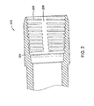
- Figure 2 is a cross sectional view of a portion of a tubular member having a box end with an axial slot extending across threads formed inside the box end.
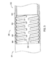
- Figure 3 is a partial cross sectional view of a connection between two tubular members with a box end cut away to illustrate a random pattern of slots in threads circumscribing a pin end.
- Figure 4 is an elevation view schematically showing tubular members within a borehole and a representative expander tool at a connection according to aspects of the invention between two of the tubular members.
- Figure 1 shows a portion of a tubular member 102 having a pin end 104 with an axial slot 106 extending across a helical thread 108 formed on the pin end 104.
- the slot 106 interrupts the thread 108 at the same circumferential point along the entire axial length of the pin end 104.
- the slot 106 extends across only a portion of the pin end 104 such that at least some individual turns of the thread 108 are continuous through the 360° of one turn.
- the slot 106 preferably extends from the crest of the thread 108 to a depth no greater than the root of the thread 108.
- any standard pin end can be modified by cutting the slot 106 axially across the thread 108.
- multiple slots may be spaced around the circumference of the thread 108.
- both the slot 106 and an additional slot 103 interrupt the thread 108 within a single 360° turn of the thread 108.
- the slots 103, 106 may be parallel or non-parallel to one another.
- the additional slot 103 can extend across only a portion of the pin end 104 as shown or can extend across the entire axial length of the pin end 104.
- the size and shape of the slot(s) can vary.
- the slot(s) can be at an angle or curved.
- the slots described herein represent no impediment to the make-up or break-out of a box by pin connection prior to expansion. Specifically, the thread continues as a normal thread on each side of the slot even though the thread is not continuous due to the slot.
- Figure 2 illustrates a portion of a tubular member 202 having a box end 204 with an axial slot 206 extending across threads 208 formed inside the box end 204.
- the slot 206 in the box end 204 serves a similar function and may be modified in a similar manner as the slot 106 in the pin end 104.
- Connections according to embodiments of the invention include those formed between tubular members that have the slot disposed in either or both of the pin or box ends.
- Figure 3 shows a connection 360 between a first tubular member 301 and a second tubular member 302 with a box end 304 of the second tubular member 302 cut away to illustrate a random pattern of a slot 306 disposed along a thread 308 circumscribing a pin end 303 of the first tubular member 301.
- the thread 308 of the pin end 303 mates with a corresponding thread 309 of the box end 304.
- the slot 306 cuts through individual turns of the thread 308 at various locations around the circumference of the pin end 303.
- the slot 306 interrupts the thread 308 at different circumferential points along the axial length of the pin end 303.
- the random pattern can be applied to a slot (not shown) in the corresponding thread 309 of the box end 304 as an alternative to or in combination with the slot 306 in the pin end 303 without departing from the scope of the invention.
- Figure 4 illustrates embodiments of the invention in use within a wellbore 10. Accordingly, Figure 4 shows a representative rig 2, a ground surface 6, a formation 4, a drill string or running string 8, a first tubular member 101, a second tubular member 201, a representative expander tool 40 comprising a body 42 and an extendable member 45 or roller, a bore 400 running through the tubular members, and a connection 60 or joint between the first tubular member 101 and the second tubular member 201.
- the first tubular member 101 and the second tubular member 201 are mated together at the surface 6 according to normal stab-in and threading procedures.
- the stab-in procedures can be preformed with tubular members arranged in a pin up and a box down configuration or a configuration with the pin down and the box up.
- the tubular members can be expanded from within by any method known to those skilled in the art.
- the expansion process can be run in any axial and/or rotational direction within the tubular members 101, 201 without risk of the connection rotating and loosening since the connection 60 becomes torsionally locked after being expanded as described below.
- the running string 8 with an expander tool 40 attached thereto runs through the bore 400 of the tubular members. At a desired location, an operator expands the tubular members using the expander tool 40.
- connection 60 between the first tubular member 101 and the second tubular member 201 When the expander tool 40 reaches the connection 60 between the first tubular member 101 and the second tubular member 201, an internal wall of a pin end expands into an internal wall of a box end.
- the connection 60 between the tubular members 101, 201 is capable of being expanded without losing its mechanical integrity.
- the threads of either the box or pin end are forced via plastic flow into a slot (e.g., the slots 106, 206 and/or 306 illustrated in Figures 1-3) on the corresponding thread of the other end. This results in locking the first and second tubular member 101, 201 together, thereby preventing rotation across the connection or relative rotation between the tubular members 101, 201.
- any rotation translated to the tubular members 101, 201 from rotation of the expander tool 40 cannot operate to break-out the connection 60 once the connection is expanded.
- the plastic flow of material into the slots which are disclosed herein upon expansion of the connection can be caused to occur based at least on differential movement between the pin and box ends due to the expansion.
- the pin end tends to elongate while the box end tends to contract when expanding the connection using rotary expansion methods.
- both the pin and box end can shrink with the relative amount of shrinkage of each end being sufficiently different to create the differential movement that at least enhances flow of material into the slots to lock the connection.
- the expandable tubular members 101, 201 with the connection 60 can be part of a liner, an open hole or cased hole patch that is run-in to a predetermined location or any other type of expandable tubular string for use in a well.
- a method in accordance with embodiments of the invention includes providing a first end of a first expandable tubular member and a second end of a second expandable tubular member, wherein a slot is disposed to intersect a circumference of a thread profile of the first end, the thread profile continuing on both sides of the slot, threading the first and second ends of the expandable tubular members to form a connection therebetween, and expanding the connection with a radial force.
- the method can further include running the expandable tubular members into a wellbore.
- the expanding of the connection can include extending extendable members of an expander tool and then rotating and axially translating the expander tool across the connection.
Landscapes
- Engineering & Computer Science (AREA)
- Life Sciences & Earth Sciences (AREA)
- Geology (AREA)
- Mining & Mineral Resources (AREA)
- Physics & Mathematics (AREA)
- Environmental & Geological Engineering (AREA)
- Fluid Mechanics (AREA)
- General Life Sciences & Earth Sciences (AREA)
- Geochemistry & Mineralogy (AREA)
- Mechanical Engineering (AREA)
- Earth Drilling (AREA)
- Mutual Connection Of Rods And Tubes (AREA)
Abstract
Description
- Embodiments of the invention generally relate to tubular connections.
- In order to access hydrocarbons in subsurface formations, it is typically necessary to drill a bore into the earth. The process of drilling a borehole and of subsequently completing the borehole in order to form a wellbore requires the use of various tubular strings. These tubular members are typically run downhole where the mechanical and seal integrity of the jointed connections are critically important in the original make-up of the tubular members, during expansion of the tubular members, and after expansion of the tubular members.
- Typically, simple male to female threaded connections connect multiple tubular members end-to-end. The male end is generally referred to as a pin, and the female end as a box. The tubular members are connected, or "made-up," by transmitting torque against one of the tubular members while the other tubular member is typically held stationary. Transmitting torque in a single direction corresponding with connection make-up tightens the threaded joint in order to establish the seal integrity and lock in the applied torque.
- When running tubular members, there is sometimes a requirement to run jointed tubular members that will later be expanded by various types of expansion mechanisms. The most basic type of expander tool employs a simple cone-shaped body, which is typically run into a wellbore to the tubular member that is to be expanded. The expander tool is then forced through the tubular members to be expanded by pushing or pulling on the working string from the surface and/or applying fluid pressure on one side of the cone. Alternatively, rotary expander tools can employ one or more rows of compliant rollers that are urged outwardly from a body of the expander tool in order to engage and to expand the surrounding tubular member. The rotary expander tool is rotated downhole so that the actuated rollers can act against the inner surface of the tubular member to be expanded in order to expand the tubular body circumferentially. Radial expander tools are described in
U.S. Patent 6,457,532, issued to Simpson et al. , and that patent is incorporated herein by reference in its entirety. - Expanding tubular members that use the same threaded connections as employed with conventional oil-field tubular members proves to be problematic. First, changes in geometry of the connection once expanded can reduce the locked in torque and the tensile capacity of the connection due to loss of intimate contact between the threads when the locked in torque is reduced. Additionally, a threaded connection potentially turns and loosens during expansion due to rotation and frictional contact of a rotary expansion tool. For example, left hand threaded box by pin connections rotate in the clockwise direction when expanded with the rotary expansion tool in the clockwise direction. This transferred rotation potentially slackens off the threaded connections within a multiple joint tubular string being expanded that is differentially stuck at the bottom when expansion takes place top down. On the other hand, transferred clockwise rotation from the rotary expansion tool potentially loosens the threaded connection regardless of differential sticking when expansion occurs in a bottom to top direction. Addition of right hand threaded connections for use in the tubular string to help remedy these problems related to undoing of the connection during expansion only present further issues such as inventory concerns and specialized equipment requirements.
- Therefore, a need exists for an improved tubular connection that is capable of being made-up and broken-out numerous times prior to expansion while torsionally locking itself upon being expanded.
- Embodiments of the invention generally relate to threaded tubular ends having a slot cut across a thread at a location along the circumference of the thread. A connection according to embodiments of the invention includes those formed between two tubular members that have the slot disposed in either or both of a pin or box end of the tubular members. The slots represent no impediment to the make-up or break-out of a box by pin connection prior to expansion. During expansion of the connection, the threads of either the box or pin end are forced via plastic flow into the slot in the corresponding thread. This results in locking the connection and preventing relative rotation between the two tubular members, which could otherwise loosen the connection.
- So that the manner in which the above recited features of the present invention can be understood in detail, a more particular description of the invention, briefly summarized above, may be had by reference to embodiments, some of which are illustrated in the appended drawings. It is to be noted, however, that the appended drawings illustrate only typical embodiments of this invention and are therefore not to be considered limiting of its scope, for the invention may admit to other equally effective embodiments.
- Figure 1 is a side view of a portion of a tubular member having a pin end with an axial slot extending across threads formed on the pin end.
- Figure 2 is a cross sectional view of a portion of a tubular member having a box end with an axial slot extending across threads formed inside the box end.
- Figure 3 is a partial cross sectional view of a connection between two tubular members with a box end cut away to illustrate a random pattern of slots in threads circumscribing a pin end.
- Figure 4 is an elevation view schematically showing tubular members within a borehole and a representative expander tool at a connection according to aspects of the invention between two of the tubular members.
- Figure 1 shows a portion of a
tubular member 102 having apin end 104 with anaxial slot 106 extending across ahelical thread 108 formed on thepin end 104. Theslot 106 interrupts thethread 108 at the same circumferential point along the entire axial length of thepin end 104. For some embodiments, theslot 106 extends across only a portion of thepin end 104 such that at least some individual turns of thethread 108 are continuous through the 360° of one turn. Theslot 106 preferably extends from the crest of thethread 108 to a depth no greater than the root of thethread 108. In general, any standard pin end can be modified by cutting theslot 106 axially across thethread 108. - As with other embodiments described herein, multiple slots may be spaced around the circumference of the
thread 108. For example, both theslot 106 and anadditional slot 103 interrupt thethread 108 within a single 360° turn of thethread 108. Theslots additional slot 103 can extend across only a portion of thepin end 104 as shown or can extend across the entire axial length of thepin end 104. Additionally, the size and shape of the slot(s) can vary. For example, the slot(s) can be at an angle or curved. Furthermore, the slots described herein represent no impediment to the make-up or break-out of a box by pin connection prior to expansion. Specifically, the thread continues as a normal thread on each side of the slot even though the thread is not continuous due to the slot. - Figure 2 illustrates a portion of a
tubular member 202 having abox end 204 with anaxial slot 206 extending acrossthreads 208 formed inside thebox end 204. Theslot 206 in thebox end 204 serves a similar function and may be modified in a similar manner as theslot 106 in thepin end 104. Connections according to embodiments of the invention include those formed between tubular members that have the slot disposed in either or both of the pin or box ends. - Figure 3 shows a
connection 360 between a firsttubular member 301 and a secondtubular member 302 with abox end 304 of the secondtubular member 302 cut away to illustrate a random pattern of aslot 306 disposed along athread 308 circumscribing apin end 303 of the firsttubular member 301. Thethread 308 of thepin end 303 mates with acorresponding thread 309 of thebox end 304. Theslot 306 cuts through individual turns of thethread 308 at various locations around the circumference of thepin end 303. In contrast to the embodiment shown in Figure 1 where theslot 106 is straight, theslot 306 interrupts thethread 308 at different circumferential points along the axial length of thepin end 303. Again, the random pattern can be applied to a slot (not shown) in thecorresponding thread 309 of thebox end 304 as an alternative to or in combination with theslot 306 in thepin end 303 without departing from the scope of the invention. - Figure 4 illustrates embodiments of the invention in use within a
wellbore 10. Accordingly, Figure 4 shows arepresentative rig 2, aground surface 6, aformation 4, a drill string or runningstring 8, a firsttubular member 101, a secondtubular member 201, arepresentative expander tool 40 comprising abody 42 and anextendable member 45 or roller, abore 400 running through the tubular members, and aconnection 60 or joint between the firsttubular member 101 and the secondtubular member 201. In operation, the firsttubular member 101 and the secondtubular member 201 are mated together at thesurface 6 according to normal stab-in and threading procedures. The stab-in procedures can be preformed with tubular members arranged in a pin up and a box down configuration or a configuration with the pin down and the box up. - After run-in, the tubular members can be expanded from within by any method known to those skilled in the art. The expansion process can be run in any axial and/or rotational direction within the
tubular members connection 60 becomes torsionally locked after being expanded as described below. The runningstring 8 with anexpander tool 40 attached thereto runs through thebore 400 of the tubular members. At a desired location, an operator expands the tubular members using theexpander tool 40. - When the
expander tool 40 reaches theconnection 60 between the firsttubular member 101 and the secondtubular member 201, an internal wall of a pin end expands into an internal wall of a box end. Theconnection 60 between thetubular members slots tubular member tubular members tubular members expander tool 40 cannot operate to break-out theconnection 60 once the connection is expanded. - The plastic flow of material into the slots which are disclosed herein upon expansion of the connection can be caused to occur based at least on differential movement between the pin and box ends due to the expansion. For example, the pin end tends to elongate while the box end tends to contract when expanding the connection using rotary expansion methods. For some expansion methods such as those utilizing a cone or expansion mandrel, both the pin and box end can shrink with the relative amount of shrinkage of each end being sufficiently different to create the differential movement that at least enhances flow of material into the slots to lock the connection.
- The expandable
tubular members connection 60 according to aspects of the invention can be part of a liner, an open hole or cased hole patch that is run-in to a predetermined location or any other type of expandable tubular string for use in a well. A method in accordance with embodiments of the invention includes providing a first end of a first expandable tubular member and a second end of a second expandable tubular member, wherein a slot is disposed to intersect a circumference of a thread profile of the first end, the thread profile continuing on both sides of the slot, threading the first and second ends of the expandable tubular members to form a connection therebetween, and expanding the connection with a radial force. The method can further include running the expandable tubular members into a wellbore. The expanding of the connection can include extending extendable members of an expander tool and then rotating and axially translating the expander tool across the connection. - While the foregoing is directed to embodiments of the present invention, other and further embodiments of the invention may be devised without departing from the basic scope thereof, and the scope thereof is determined by the claims that follow.
Claims (22)
- A wellbore tubular member having a tubular end, comprising:a thread profile disposed on the tubular end for making a threaded connection, wherein the thread profile includes a slot cut into the thread profile substantially transverse to a circumference of the thread profile, the thread profile continuing on both sides of the slot.
- The wellbore tubular member of claim 1, wherein the slot extends from a crest of the thread profile to a depth substantially equivalent to a root of the thread profile.
- The wellbore tubular member of claim 1, wherein the slot extends across substantially an entire axial length of the thread profile to intersect each turn of the thread profile.
- The wellbore tubular member of claim 3, wherein the slot interrupts the thread profile at substantially the same circumferential point of the tubular end.
- The wellbore tubular member of claim 3, wherein the slot interrupts the thread profile at different circumferential points of the tubular end.
- The wellbore tubular member of claim 1, further comprising at least one additional slot cut into the thread profile, the slot and the at least one additional slot spaced from one another on a single turn of the thread profile.
- The wellbore tubular member of claim 6, wherein the slot and the at least one additional slot are non-parallel to one another.
- A wellbore tubular connection, comprising:a tubular pin member having a thread disposed on an outside surface thereof;a tubular box member having a corresponding thread disposed on an inside surface thereof for mating with the thread of the pin member; anda slot disposed to intersect a circumference of one of the threads, which continues on both sides of the slot.
- The wellbore tubular connection of claim 8, wherein the slot is provided in the thread of the pin member.
- The wellbore tubular connection of claim 8, wherein the slot is provided in the corresponding thread of the box member.
- The wellbore tubular connection of claim 8, wherein the slot is provided in the corresponding thread of the box member and an additional slot is provided in the thread of the pin member.
- The wellbore tubular connection of claim 8, wherein the slot extends across substantially an entire axial length of the one of the threads to intersect each turn thereof.
- The wellbore tubular connection of claim 8, wherein the slot interrupts the one of the threads at substantially the same circumferential point along an entire axial length thereof.
- The wellbore tubular connection of claim 8, wherein the slot interrupts the one of the threads at different circumferential points along an axial length thereof.
- The wellbore tubular connection of claim 8, wherein the pin and box members are disposed within a tubular string located in a wellbore.
- A method of expanding a connection between two expandable tubular members,providing a first end of a first expandable tubular member and a second end of a second expandable tubular member, wherein a slot is disposed to intersect a circumference of a thread profile of the first end, the thread profile continuing on both sides of the slot;threading the first and second ends of the expandable tubular members to form a connection therebetween; andexpanding the connection with a radial force, thereby rotationally locking the connection.
- The method of claim 16, further comprising running the expandable tubular members into a wellbore.
- The method of claim 16, wherein expanding the connection rotationally locks the connection by causing a corresponding thread profile of the second end to plastically flow into the slot in the thread profile of the first end.
- The method of claim 16, wherein expanding the connection includes rotating an expander tool.
- The method of claim 16, wherein expanding the connection includes rotating and axially translating an expander tool.
- The method of claim 16, wherein expanding the connection includes extending extendable members of an expander tool and then rotating and axially translating the expander tool across the connection.
- A method for locking an expandable threaded connection, comprising:providing a first tubular having a first threaded end;providing a second tubular having a second threaded end, wherein at least one of the first and second threaded ends includes an interrupted thread form;engaging the first and second threaded ends; andexpanding the first and second threaded ends that are engaged, thereby locating an abutment of the interrupted thread into locking engagement with a respective one of the first and second threaded ends.
Applications Claiming Priority (1)
| Application Number | Priority Date | Filing Date | Title |
|---|---|---|---|
| US11/224,832 US7591059B2 (en) | 2005-09-13 | 2005-09-13 | Expansion activated anti-rotation device |
Publications (2)
| Publication Number | Publication Date |
|---|---|
| EP1762695A1 true EP1762695A1 (en) | 2007-03-14 |
| EP1762695B1 EP1762695B1 (en) | 2008-12-10 |
Family
ID=37575262
Family Applications (1)
| Application Number | Title | Priority Date | Filing Date |
|---|---|---|---|
| EP06120496A Not-in-force EP1762695B1 (en) | 2005-09-13 | 2006-09-12 | Expansion activated anti-rotation device |
Country Status (4)
| Country | Link |
|---|---|
| US (1) | US7591059B2 (en) |
| EP (1) | EP1762695B1 (en) |
| CA (1) | CA2559469C (en) |
| DE (1) | DE602006004122D1 (en) |
Cited By (2)
| Publication number | Priority date | Publication date | Assignee | Title |
|---|---|---|---|---|
| EP2655788A4 (en) * | 2010-12-21 | 2016-08-17 | Enventure Global Technology | BACKGROUND RELEASE JOINT WITH RADIALLY EXPANDABLE ELEMENT |
| EP3390766A4 (en) * | 2015-12-16 | 2019-05-22 | Enventure Global Technology Inc. | TUBULAR ELEMENTS AT THE BOTTOM OF A HOLE WITH HERMETICALLY REFLECTIVE CONNECTION |
Families Citing this family (6)
| Publication number | Priority date | Publication date | Assignee | Title |
|---|---|---|---|---|
| AT509643B1 (en) * | 2010-04-07 | 2013-08-15 | Dywidag Systems Int Gmbh | TWO-PIECE DRILLING TOOL FOR HANDLING OR DRILLING HOLES IN FLOOR OR ROCK MATERIALS |
| US8398123B1 (en) * | 2010-04-09 | 2013-03-19 | Felix L. Sorkin | Duct coupling system |
| US9328760B2 (en) * | 2012-06-20 | 2016-05-03 | Earth Tool Company Llc | Quick connect rods |
| WO2018071882A1 (en) * | 2016-10-14 | 2018-04-19 | Transocean Sedco Forex Ventures Limited | Connector assemblies for connecting tubulars and related methods |
| US11927011B2 (en) | 2020-04-15 | 2024-03-12 | Felix Sorkin | Closure load plug |
| WO2025168970A1 (en) * | 2024-02-08 | 2025-08-14 | Deep Casing Tools, Ltd. | Double shoulder threaded connector for well pipe having removable insert |
Citations (5)
| Publication number | Priority date | Publication date | Assignee | Title |
|---|---|---|---|---|
| US2051525A (en) * | 1933-11-17 | 1936-08-18 | Globe Oil Tools Co | Rock drill bit |
| US3717368A (en) * | 1969-10-22 | 1973-02-20 | Fagersta Bruks Ab | Connection thread system for sets of extension drill rods |
| GB2095360A (en) * | 1981-03-19 | 1982-09-29 | Ingersoll Rand Co | A thread system |
| WO2000057020A1 (en) * | 1999-03-22 | 2000-09-28 | Well Engineering Partners B.V. | Pipe coupling and pipe section with auxiliary connections |
| EP1403464A2 (en) * | 2002-09-25 | 2004-03-31 | Weatherford/Lamb, Inc. | Expandable tubular connection |
Family Cites Families (16)
| Publication number | Priority date | Publication date | Assignee | Title |
|---|---|---|---|---|
| US2673751A (en) * | 1950-12-05 | 1954-03-30 | Jones & Laughlin Steel Corp | Metal pipe and coupling therefor |
| US3895829A (en) * | 1974-02-04 | 1975-07-22 | Halliburton Co | Releasable pipe connector |
| US6789822B1 (en) | 1997-03-21 | 2004-09-14 | Weatherford/Lamb, Inc. | Expandable slotted tubing string and method for connecting such a tubing string |
| US6283511B1 (en) * | 1998-08-24 | 2001-09-04 | Well Engineering Partners, B.V. | Pipe coupling |
| EP1147287B1 (en) * | 1998-12-22 | 2005-08-17 | Weatherford/Lamb, Inc. | Procedures and equipment for profiling and jointing of pipes |
| FR2811056B1 (en) * | 2000-06-30 | 2003-05-16 | Vallourec Mannesmann Oil & Gas | TUBULAR THREADED JOINT SUITABLE FOR DIAMETRIC EXPANSION |
| US6607220B2 (en) * | 2001-10-09 | 2003-08-19 | Hydril Company | Radially expandable tubular connection |
| US6767035B2 (en) | 2002-03-11 | 2004-07-27 | Weatherford/Lamb, Inc. | High torque modified profile threaded tubular connection |
| US6971685B2 (en) | 2002-06-24 | 2005-12-06 | Weatherford/Lamb, Inc. | Multi-point high pressure seal for expandable tubular connections |
| GB0215668D0 (en) | 2002-07-06 | 2002-08-14 | Weatherford Lamb | Coupling tubulars |
| GB0221220D0 (en) | 2002-09-13 | 2002-10-23 | Weatherford Lamb | Expanding coupling |
| US6920932B2 (en) | 2003-04-07 | 2005-07-26 | Weatherford/Lamb, Inc. | Joint for use with expandable tubulars |
| US6860525B2 (en) * | 2003-04-17 | 2005-03-01 | Dtc International, Inc. | Breech lock connector for a subsea riser |
| US7025135B2 (en) | 2003-05-22 | 2006-04-11 | Weatherford/Lamb, Inc. | Thread integrity feature for expandable connections |
| US7513537B2 (en) * | 2003-10-22 | 2009-04-07 | Frank's Casing Crew & Rental Tools, Inc. | Tubular connection with slotted threads |
| US7077197B2 (en) | 2003-12-19 | 2006-07-18 | Weatherford/Lamb, Inc. | Expandable tubular connection |
-
2005
- 2005-09-13 US US11/224,832 patent/US7591059B2/en not_active Expired - Fee Related
-
2006
- 2006-09-12 CA CA002559469A patent/CA2559469C/en not_active Expired - Fee Related
- 2006-09-12 EP EP06120496A patent/EP1762695B1/en not_active Not-in-force
- 2006-09-12 DE DE602006004122T patent/DE602006004122D1/en active Active
Patent Citations (5)
| Publication number | Priority date | Publication date | Assignee | Title |
|---|---|---|---|---|
| US2051525A (en) * | 1933-11-17 | 1936-08-18 | Globe Oil Tools Co | Rock drill bit |
| US3717368A (en) * | 1969-10-22 | 1973-02-20 | Fagersta Bruks Ab | Connection thread system for sets of extension drill rods |
| GB2095360A (en) * | 1981-03-19 | 1982-09-29 | Ingersoll Rand Co | A thread system |
| WO2000057020A1 (en) * | 1999-03-22 | 2000-09-28 | Well Engineering Partners B.V. | Pipe coupling and pipe section with auxiliary connections |
| EP1403464A2 (en) * | 2002-09-25 | 2004-03-31 | Weatherford/Lamb, Inc. | Expandable tubular connection |
Cited By (2)
| Publication number | Priority date | Publication date | Assignee | Title |
|---|---|---|---|---|
| EP2655788A4 (en) * | 2010-12-21 | 2016-08-17 | Enventure Global Technology | BACKGROUND RELEASE JOINT WITH RADIALLY EXPANDABLE ELEMENT |
| EP3390766A4 (en) * | 2015-12-16 | 2019-05-22 | Enventure Global Technology Inc. | TUBULAR ELEMENTS AT THE BOTTOM OF A HOLE WITH HERMETICALLY REFLECTIVE CONNECTION |
Also Published As
| Publication number | Publication date |
|---|---|
| US20070057508A1 (en) | 2007-03-15 |
| CA2559469C (en) | 2009-11-10 |
| US7591059B2 (en) | 2009-09-22 |
| CA2559469A1 (en) | 2007-03-13 |
| EP1762695B1 (en) | 2008-12-10 |
| DE602006004122D1 (en) | 2009-01-22 |
Similar Documents
| Publication | Publication Date | Title |
|---|---|---|
| CA2467899C (en) | Thread integrity feature for expandable connections | |
| CA2452238C (en) | Wire lock expandable connection | |
| CA2472547C (en) | Centraliser | |
| EP1403464B1 (en) | Expandable tubular connection | |
| US20050011650A1 (en) | Method and apparatus for expanding and separating tubulars in a wellbore | |
| US20080007060A1 (en) | Coupling tubulars | |
| US8181707B2 (en) | Apparatus and methods to protect connections | |
| CA2490506C (en) | Expandable tubular connection | |
| US7591059B2 (en) | Expansion activated anti-rotation device | |
| US20120012397A1 (en) | Expandable Tool for an Earth Boring System | |
| US20190345787A1 (en) | Method for removing casing from a wellbore | |
| US20050230154A1 (en) | Downhole drill string having a collapsible subassembly | |
| EP1482124B1 (en) | Non-rotating expandable connection with collapsing type seal | |
| WO2023094483A2 (en) | Anchor mechanism | |
| WO2008097226A1 (en) | Expandable tubular connection | |
| GB2373274A (en) | Soft release coupling of use with two tubing strings | |
| GB2505198A (en) | Seal with a tubular net reinforcement |
Legal Events
| Date | Code | Title | Description |
|---|---|---|---|
| PUAI | Public reference made under article 153(3) epc to a published international application that has entered the european phase |
Free format text: ORIGINAL CODE: 0009012 |
|
| AK | Designated contracting states |
Kind code of ref document: A1 Designated state(s): AT BE BG CH CY CZ DE DK EE ES FI FR GB GR HU IE IS IT LI LT LU LV MC NL PL PT RO SE SI SK TR |
|
| AX | Request for extension of the european patent |
Extension state: AL BA HR MK YU |
|
| 17P | Request for examination filed |
Effective date: 20070803 |
|
| 17Q | First examination report despatched |
Effective date: 20070910 |
|
| AKX | Designation fees paid |
Designated state(s): DE FR GB |
|
| GRAP | Despatch of communication of intention to grant a patent |
Free format text: ORIGINAL CODE: EPIDOSNIGR1 |
|
| GRAS | Grant fee paid |
Free format text: ORIGINAL CODE: EPIDOSNIGR3 |
|
| GRAA | (expected) grant |
Free format text: ORIGINAL CODE: 0009210 |
|
| AK | Designated contracting states |
Kind code of ref document: B1 Designated state(s): DE FR GB |
|
| REG | Reference to a national code |
Ref country code: GB Ref legal event code: FG4D |
|
| REF | Corresponds to: |
Ref document number: 602006004122 Country of ref document: DE Date of ref document: 20090122 Kind code of ref document: P |
|
| PLBE | No opposition filed within time limit |
Free format text: ORIGINAL CODE: 0009261 |
|
| STAA | Information on the status of an ep patent application or granted ep patent |
Free format text: STATUS: NO OPPOSITION FILED WITHIN TIME LIMIT |
|
| 26N | No opposition filed |
Effective date: 20090911 |
|
| REG | Reference to a national code |
Ref country code: DE Ref legal event code: R082 Ref document number: 602006004122 Country of ref document: DE Representative=s name: FIENER, JOSEF, DE |
|
| REG | Reference to a national code |
Ref country code: DE Ref legal event code: R081 Ref document number: 602006004122 Country of ref document: DE Owner name: WEATHERFORD TECHNOLOGY HOLDINGS, LLC, HOUSTON, US Free format text: FORMER OWNER: WEATHERFORD/LAMB, INC., HOUSTON, TEX., US Effective date: 20150417 Ref country code: DE Ref legal event code: R082 Ref document number: 602006004122 Country of ref document: DE Representative=s name: FIENER, JOSEF, DE Effective date: 20150417 |
|
| REG | Reference to a national code |
Ref country code: FR Ref legal event code: TP Owner name: WEATHERFORD TECHNOLOGY HOLDINGS, LLC, US Effective date: 20150603 |
|
| PGFP | Annual fee paid to national office [announced via postgrant information from national office to epo] |
Ref country code: GB Payment date: 20150909 Year of fee payment: 10 Ref country code: DE Payment date: 20150908 Year of fee payment: 10 |
|
| REG | Reference to a national code |
Ref country code: GB Ref legal event code: 732E Free format text: REGISTERED BETWEEN 20151029 AND 20151104 |
|
| REG | Reference to a national code |
Ref country code: FR Ref legal event code: PLFP Year of fee payment: 11 |
|
| PGFP | Annual fee paid to national office [announced via postgrant information from national office to epo] |
Ref country code: FR Payment date: 20160816 Year of fee payment: 11 |
|
| REG | Reference to a national code |
Ref country code: DE Ref legal event code: R119 Ref document number: 602006004122 Country of ref document: DE |
|
| GBPC | Gb: european patent ceased through non-payment of renewal fee |
Effective date: 20160912 |
|
| PG25 | Lapsed in a contracting state [announced via postgrant information from national office to epo] |
Ref country code: GB Free format text: LAPSE BECAUSE OF NON-PAYMENT OF DUE FEES Effective date: 20160912 Ref country code: DE Free format text: LAPSE BECAUSE OF NON-PAYMENT OF DUE FEES Effective date: 20170401 |
|
| REG | Reference to a national code |
Ref country code: FR Ref legal event code: ST Effective date: 20180531 |
|
| PG25 | Lapsed in a contracting state [announced via postgrant information from national office to epo] |
Ref country code: FR Free format text: LAPSE BECAUSE OF NON-PAYMENT OF DUE FEES Effective date: 20171002 |