EP1762491A2 - Deoxygenated fuel-cooler environmental control system pre-cooler for an aircraft - Google Patents
Deoxygenated fuel-cooler environmental control system pre-cooler for an aircraft Download PDFInfo
- Publication number
- EP1762491A2 EP1762491A2 EP06254611A EP06254611A EP1762491A2 EP 1762491 A2 EP1762491 A2 EP 1762491A2 EP 06254611 A EP06254611 A EP 06254611A EP 06254611 A EP06254611 A EP 06254611A EP 1762491 A2 EP1762491 A2 EP 1762491A2
- Authority
- EP
- European Patent Office
- Prior art keywords
- fuel
- heat exchanger
- liquid
- thermal management
- recited
- Prior art date
- Legal status (The legal status is an assumption and is not a legal conclusion. Google has not performed a legal analysis and makes no representation as to the accuracy of the status listed.)
- Withdrawn
Links
- 230000007613 environmental effect Effects 0.000 title claims abstract description 13
- 239000000446 fuel Substances 0.000 claims abstract description 47
- 230000006641 stabilisation Effects 0.000 claims abstract description 7
- 238000011105 stabilization Methods 0.000 claims abstract description 7
- 239000007788 liquid Substances 0.000 claims description 8
- 238000006392 deoxygenation reaction Methods 0.000 claims description 5
- 238000006243 chemical reaction Methods 0.000 claims description 4
- 230000003635 deoxygenating effect Effects 0.000 claims description 2
- 238000000034 method Methods 0.000 claims 4
- 239000012530 fluid Substances 0.000 claims 1
- 238000004939 coking Methods 0.000 abstract description 4
- 230000008901 benefit Effects 0.000 description 4
- 238000001816 cooling Methods 0.000 description 3
- 239000007789 gas Substances 0.000 description 3
- QVGXLLKOCUKJST-UHFFFAOYSA-N atomic oxygen Chemical compound [O] QVGXLLKOCUKJST-UHFFFAOYSA-N 0.000 description 2
- 238000012986 modification Methods 0.000 description 2
- 230000004048 modification Effects 0.000 description 2
- 239000001301 oxygen Substances 0.000 description 2
- 229910052760 oxygen Inorganic materials 0.000 description 2
- 239000004215 Carbon black (E152) Substances 0.000 description 1
- 238000006701 autoxidation reaction Methods 0.000 description 1
- 238000002485 combustion reaction Methods 0.000 description 1
- 230000001143 conditioned effect Effects 0.000 description 1
- 239000002826 coolant Substances 0.000 description 1
- 238000010586 diagram Methods 0.000 description 1
- 238000001537 electron coincidence spectroscopy Methods 0.000 description 1
- 239000002828 fuel tank Substances 0.000 description 1
- 238000010438 heat treatment Methods 0.000 description 1
- 229930195733 hydrocarbon Natural products 0.000 description 1
- 150000002430 hydrocarbons Chemical class 0.000 description 1
- 230000003993 interaction Effects 0.000 description 1
Images
Classifications
-
- B—PERFORMING OPERATIONS; TRANSPORTING
- B64—AIRCRAFT; AVIATION; COSMONAUTICS
- B64D—EQUIPMENT FOR FITTING IN OR TO AIRCRAFT; FLIGHT SUITS; PARACHUTES; ARRANGEMENT OR MOUNTING OF POWER PLANTS OR PROPULSION TRANSMISSIONS IN AIRCRAFT
- B64D13/00—Arrangements or adaptations of air-treatment apparatus for aircraft crew or passengers, or freight space
- B64D13/06—Arrangements or adaptations of air-treatment apparatus for aircraft crew or passengers, or freight space the air being conditioned
-
- B—PERFORMING OPERATIONS; TRANSPORTING
- B01—PHYSICAL OR CHEMICAL PROCESSES OR APPARATUS IN GENERAL
- B01D—SEPARATION
- B01D19/00—Degasification of liquids
-
- B—PERFORMING OPERATIONS; TRANSPORTING
- B64—AIRCRAFT; AVIATION; COSMONAUTICS
- B64D—EQUIPMENT FOR FITTING IN OR TO AIRCRAFT; FLIGHT SUITS; PARACHUTES; ARRANGEMENT OR MOUNTING OF POWER PLANTS OR PROPULSION TRANSMISSIONS IN AIRCRAFT
- B64D37/00—Arrangements in connection with fuel supply for power plant
- B64D37/32—Safety measures not otherwise provided for, e.g. preventing explosive conditions
-
- B—PERFORMING OPERATIONS; TRANSPORTING
- B64—AIRCRAFT; AVIATION; COSMONAUTICS
- B64D—EQUIPMENT FOR FITTING IN OR TO AIRCRAFT; FLIGHT SUITS; PARACHUTES; ARRANGEMENT OR MOUNTING OF POWER PLANTS OR PROPULSION TRANSMISSIONS IN AIRCRAFT
- B64D13/00—Arrangements or adaptations of air-treatment apparatus for aircraft crew or passengers, or freight space
- B64D13/06—Arrangements or adaptations of air-treatment apparatus for aircraft crew or passengers, or freight space the air being conditioned
- B64D2013/0603—Environmental Control Systems
- B64D2013/0659—Environmental Control Systems comprising provisions for cooling fuel systems
-
- Y—GENERAL TAGGING OF NEW TECHNOLOGICAL DEVELOPMENTS; GENERAL TAGGING OF CROSS-SECTIONAL TECHNOLOGIES SPANNING OVER SEVERAL SECTIONS OF THE IPC; TECHNICAL SUBJECTS COVERED BY FORMER USPC CROSS-REFERENCE ART COLLECTIONS [XRACs] AND DIGESTS
- Y02—TECHNOLOGIES OR APPLICATIONS FOR MITIGATION OR ADAPTATION AGAINST CLIMATE CHANGE
- Y02T—CLIMATE CHANGE MITIGATION TECHNOLOGIES RELATED TO TRANSPORTATION
- Y02T50/00—Aeronautics or air transport
- Y02T50/50—On board measures aiming to increase energy efficiency
Definitions
- the present invention relates to a thermal management system, and more particularly to a thermal management system which utilizes a fuel stabilization unit with a fuel-air pre-cooler for an aircraft environmental control system.
- Aircraft utilize sophisticated Thermal Management Systems (TMS) for component and environmental thermal management.
- An environmental control system (ECS) provides a supply of conditioned air to an enclosure, such as an aircraft cabin and cockpit.
- ECSs have utilized an air cycle cooling system which is in a heat exchange relationship with a liquid loop.
- the liquid loop typically cools other heat loads such as avionics packages. Interaction between the air and liquid subsystems is relatively complex.
- a flow of bleed air is drawn from an intermediate or high pressure engine compressor section of a gas turbine engine.
- a penalty paid for the use of bleed air is a reduction in operating efficiency of the engine from which the air is bled.
- the bleed air is often above 700 degrees Fahrenheit (371°C) and must be pre-cooled to below 450 degrees Fahrenheit (232°C) in an engine pylon mounted air-to-air heat exchanger prior to being communicated through the aircraft wing and into the ECS.
- the cooler air communicated to the air-to-air heat exchanger is fan bypass airflow drawn from a fan section of the of the aircraft engine.
- the fan bypass airflow is air drawn from the fan duct of a gas turbine engine which further reduces the operating efficiency of the engine.
- a fuel based thermal management system includes a fuel stabilization system which permits the fuel to exceed the traditional coking temperatures.
- An air-to-fuel heat exchanger operates as an environmental control system (ECS) pre-cooler such that the heat from the engine compressor bleed air is rejected into the fuel.
- ECS environmental control system
- the deoxygenated fuel air-to-fuel heat exchanger minimizes drawing of engine bypass airflow with a conventional air-to-air pre-cooler which would otherwise decrease engine operating efficiency.
- the present invention therefore provides an effective, lightweight thermal management system for an aircraft ECS which minimizes reduction in engine operating efficiency.
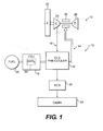
- FIG. 1 illustrates a general perspective view of a fuel based thermal management system (TMS) 10 for an energy conversion device (ECD) 12.
- TMS fuel based thermal management system
- ECD energy conversion device
- FIG. 1 illustrates a general perspective view of a fuel based thermal management system (TMS) 10 for an energy conversion device (ECD) 12.
- the TMS includes a fuel circuit 14 and an environmental control system circuit 16.
- a fuel stabilization system (FSU) 18 receives a liquid fuel from a fuel tank system 20 (illustrated schematically). It should be understood that the location of the FSU 18 represents only one of many possible locations, and that the FSU may be located in other locations while still deoxygenating the fuel to be advantageously utilized at higher temperatures with high temperature resistant components.
- the ECD 12 may exist in a variety of forms in which the fuel, at some point prior to eventual use for processing, for combustion or for some form of energy release, acquires sufficient heat to support autoxidation reactions and coking if dissolved oxygen is present to any significant extent in the fuel.
- One form of the ECD 12 is a gas turbine engine, and particularly a turbofan engine illustrated schematically which includes a fan section 22, a compressor section 24, a turbine section 26, and a combustor section 28.
- the fuel is typically a hydrocarbon such as a liquid jet fuel.
- the FSU 18 includes a fuel deoxygenation system 30 which permits the fuel to remain stable at much higher temperatures without coking by removing dissolved oxygen from the liquid fuel which enables higher temperature loads to reject their heat to the fuel. It should be understood that various deoxygenation systems will benefit from the present invention. For further understanding of a fuel deoxygenator system and associated components thereof, attention is directed to United States Patent Nos. 6,315,815 and 6,709,492 which are assigned to the assignee of the instant invention and which are hereby incorporated herein in their entirety.
- the fuel in the fuel circuit 14 serves as a coolant for the environmental control system (ECS) circuit 16 to absorb thermal energy therefrom prior to the elevated temperature fuel being communication to the combustor section 28 of the ECD 12.
- ECS environmental control system
- heating of the fuel increases efficiency of the ECD 12.
- the deoxygenation system 30 permits fuel to accommodate temperatures upwards of 900 degrees Fahrenheit (482°C).
- a liquid-to-air heat exchanger system 32 is located at an intersection between the circuits 14, 16.
- the liquid-to-air heat exchanger system 32 is embodied herein as an ECS pre-cooler, however, other subsystems which require thermal management will likewise benefit from the present invention and that other heat exchanger subsystems may be incorporated into the TMS 10. It should be understood that various precautions may be preferably taken due to the close proximity of the compressed air with the high temperature deoxygenated fuel, however, such precautions are well within one of reasonable skill in the thermal management art.
- the ECS circuit 14 receives compressed air from the compressor section 24 of the ECD 12.
- the compressed air is communicated through the liquid-to-air heat exchanger system 32 prior to communication to an aircraft cabin 34 through an aircraft environmental control system (ECS) 36.
- the liquid-to-air heat exchanger system 32 preferably reduces the temperature of the compressed engine air to approximately 300 degrees Fahrenheit (149°C) prior to further conventional cooling in the ECS 36 for distribution to the cabin 34 as generally understood.
- the deoxygenated fuel is preferably raised to a temperature which exceeds 325 degrees Fahrenheit (163°C) in the liquid-to-air heat exchanger system 32 prior to communication to the combustor section of the ECD 12.
- This and greater temperatures are available due to the deoxygenation system 30 which permits the deoxygenated fuel to accommodate temperatures upwards of 900 degrees Fahrenheit (482°C).
- the performance of the ECD 12 is improved with otherwise wasted thermal energy.
- the increased cooling of the compressed air prior to communication to the ECS 36 due to the air-to-liquid heat exchanger system 32 advantageously minimizes the size and/or weight of this and other heat exchangers associated with the ECS 36. Such thermal management avoids or minimizes the usage of fan bypass air which would otherwise reduce engine operating efficiency.
Landscapes
- Engineering & Computer Science (AREA)
- Aviation & Aerospace Engineering (AREA)
- Health & Medical Sciences (AREA)
- General Health & Medical Sciences (AREA)
- Pulmonology (AREA)
- Chemical & Material Sciences (AREA)
- Chemical Kinetics & Catalysis (AREA)
- Production Of Liquid Hydrocarbon Mixture For Refining Petroleum (AREA)
- Turbine Rotor Nozzle Sealing (AREA)
- Feeding And Controlling Fuel (AREA)
- Engine Equipment That Uses Special Cycles (AREA)
Abstract
Description
- The present invention relates to a thermal management system, and more particularly to a thermal management system which utilizes a fuel stabilization unit with a fuel-air pre-cooler for an aircraft environmental control system.
- Aircraft utilize sophisticated Thermal Management Systems (TMS) for component and environmental thermal management. An environmental control system (ECS) provides a supply of conditioned air to an enclosure, such as an aircraft cabin and cockpit. Conventional ECSs have utilized an air cycle cooling system which is in a heat exchange relationship with a liquid loop. The liquid loop typically cools other heat loads such as avionics packages. Interaction between the air and liquid subsystems is relatively complex.
- In one conventional ECS, a flow of bleed air is drawn from an intermediate or high pressure engine compressor section of a gas turbine engine. Although effective, a penalty paid for the use of bleed air is a reduction in operating efficiency of the engine from which the air is bled. Furthermore, the bleed air is often above 700 degrees Fahrenheit (371°C) and must be pre-cooled to below 450 degrees Fahrenheit (232°C) in an engine pylon mounted air-to-air heat exchanger prior to being communicated through the aircraft wing and into the ECS. The cooler air communicated to the air-to-air heat exchanger is fan bypass airflow drawn from a fan section of the of the aircraft engine. The fan bypass airflow is air drawn from the fan duct of a gas turbine engine which further reduces the operating efficiency of the engine.
- Accordingly, it is desirable to provide an effective, lightweight thermal management system for an aircraft ECS which minimizes reduction in engine operating efficiency.
- A fuel based thermal management system according to the present invention includes a fuel stabilization system which permits the fuel to exceed the traditional coking temperatures. An air-to-fuel heat exchanger operates as an environmental control system (ECS) pre-cooler such that the heat from the engine compressor bleed air is rejected into the fuel. The deoxygenated fuel air-to-fuel heat exchanger minimizes drawing of engine bypass airflow with a conventional air-to-air pre-cooler which would otherwise decrease engine operating efficiency.
- The present invention therefore provides an effective, lightweight thermal management system for an aircraft ECS which minimizes reduction in engine operating efficiency.
- The various features and advantages of this invention will become apparent to those skilled in the art from the following detailed description of the currently preferred embodiment. The drawings that accompany the detailed description can be briefly described as follows:
- Figure 1 is a general block diagram of a thermal management system according to the present invention.
- Figure 1 illustrates a general perspective view of a fuel based thermal management system (TMS) 10 for an energy conversion device (ECD) 12. The TMS includes a
fuel circuit 14 and an environmentalcontrol system circuit 16. - A fuel stabilization system (FSU) 18 receives a liquid fuel from a fuel tank system 20 (illustrated schematically). It should be understood that the location of the FSU 18 represents only one of many possible locations, and that the FSU may be located in other locations while still deoxygenating the fuel to be advantageously utilized at higher temperatures with high temperature resistant components.
- The ECD 12 may exist in a variety of forms in which the fuel, at some point prior to eventual use for processing, for combustion or for some form of energy release, acquires sufficient heat to support autoxidation reactions and coking if dissolved oxygen is present to any significant extent in the fuel. One form of the ECD 12 is a gas turbine engine, and particularly a turbofan engine illustrated schematically which includes a
fan section 22, acompressor section 24, aturbine section 26, and acombustor section 28. - The fuel is typically a hydrocarbon such as a liquid jet fuel. The FSU 18 includes a
fuel deoxygenation system 30 which permits the fuel to remain stable at much higher temperatures without coking by removing dissolved oxygen from the liquid fuel which enables higher temperature loads to reject their heat to the fuel. It should be understood that various deoxygenation systems will benefit from the present invention. For further understanding of a fuel deoxygenator system and associated components thereof, attention is directed toUnited States Patent Nos. 6,315,815 and6,709,492 which are assigned to the assignee of the instant invention and which are hereby incorporated herein in their entirety. - The fuel in the
fuel circuit 14 serves as a coolant for the environmental control system (ECS)circuit 16 to absorb thermal energy therefrom prior to the elevated temperature fuel being communication to thecombustor section 28 of theECD 12. In general, heating of the fuel increases efficiency of theECD 12. Thedeoxygenation system 30 permits fuel to accommodate temperatures upwards of 900 degrees Fahrenheit (482°C). - A liquid-to-air
heat exchanger system 32 is located at an intersection between thecircuits heat exchanger system 32 is embodied herein as an ECS pre-cooler, however, other subsystems which require thermal management will likewise benefit from the present invention and that other heat exchanger subsystems may be incorporated into theTMS 10. It should be understood that various precautions may be preferably taken due to the close proximity of the compressed air with the high temperature deoxygenated fuel, however, such precautions are well within one of reasonable skill in the thermal management art. - The
ECS circuit 14 receives compressed air from thecompressor section 24 of theECD 12. The compressed air is communicated through the liquid-to-airheat exchanger system 32 prior to communication to anaircraft cabin 34 through an aircraft environmental control system (ECS) 36. The liquid-to-airheat exchanger system 32 preferably reduces the temperature of the compressed engine air to approximately 300 degrees Fahrenheit (149°C) prior to further conventional cooling in the ECS 36 for distribution to thecabin 34 as generally understood. - The deoxygenated fuel is preferably raised to a temperature which exceeds 325 degrees Fahrenheit (163°C) in the liquid-to-air
heat exchanger system 32 prior to communication to the combustor section of theECD 12. This and greater temperatures are available due to thedeoxygenation system 30 which permits the deoxygenated fuel to accommodate temperatures upwards of 900 degrees Fahrenheit (482°C). The performance of the ECD 12 is improved with otherwise wasted thermal energy. Moreover, the increased cooling of the compressed air prior to communication to theECS 36 due to the air-to-liquidheat exchanger system 32 advantageously minimizes the size and/or weight of this and other heat exchangers associated with theECS 36. Such thermal management avoids or minimizes the usage of fan bypass air which would otherwise reduce engine operating efficiency. - Although particular step sequences are shown, described, and claimed, it should be understood that steps may be performed in any order, separated or combined unless otherwise indicated and will still benefit from the present invention.
- The foregoing description is exemplary rather than defined by the limitations within. Many modifications and variations of the present invention are possible in light of the above teachings. The preferred embodiments of this invention have been disclosed, however, one of ordinary skill in the art would recognize that certain modifications would come within the scope of this invention. It is, therefore, to be understood that within the scope of the appended claims, the invention may be practiced otherwise than as specifically described. For that reason the following claims should be studied to determine the true scope and content of this invention.
Claims (15)
- A thermal management system (10) comprising:a fuel stabilization system (18);a liquid-to-air heat exchanger system (32) in fluid communication with said fuel stabilization system (18); andan environmental control system (36) in communication with said liquid-to-air heat exchanger system (32).
- The thermal management system as recited in claim 1, wherein said fuel stabilization system (18) comprises a deoxygenation system (30).
- The thermal management system as recited in claim 1 or 2, wherein said liquid-to-air heat exchanger (32) is in communication with compressed air from an Energy Conversion Device (12).
- The thermal management system as recited in claim 3, wherein said Energy Conversion Device (10) is an aircraft gas turbine engine.
- The thermal management system as recited in any preceding claim, wherein said liquid-to-air heat exchanger (32) is a fuel-to-air heat exchanger.
- The thermal management system as recited in any preceding claim, wherein said liquid-to-air heat exchanger (32) operates to reduce a temperature of a compressed air to approximately 300 degrees Fahrenheit (149°C).
- The thermal management system as recited in any preceding claim, wherein said liquid-to-air heat exchanger (32) operates to reduce a temperature of a compressed air to approximate a liquid inlet temperature of said liquid-to-air heat exchanger system.
- The thermal management system as recited in any preceding claim, wherein said liquid-to-air heat exchanger (32) operates with fuel at temperatures exceeding 325 degrees Fahrenheit (163°C).
- The thermal management system as recited in any preceding claim, wherein said environmental control system (36) communicates airflow to an aircraft cabin (34).
- The thermal management system as recited in any preceding claim 8, wherein said environmental control system (36) communicates airflow to an electronic device.
- The thermal management system as recited in any preceding claim, wherein fuel from said liquid-to-air heat exchanger (32) is in communication with a combustor section (28) of a or said gas turbine engine (12).
- A method of thermal management comprising the steps of:(1) deoxygenating a fuel to provide a deoxygenated fuel;(2) communicating the fuel through a liquid-to-air heat exchanger system (32);(3) communicating a compressed air from an energy conversion device (12) through the liquid-to-air heat exchanger system (32) to reject heat from the compressed air to the deoxygenated fuel; and(4) communicating the compressed air from the liquid-to-air heat exchanger (32) to an environmental control system (36).
- A method as recited in claim 12, wherein said step (3) further comprises the step of:drawing the compressed air from a compressor section (24) of a gas turbine engine (12).
- A method as recited in claim 12 or 13, wherein said step (3) further comprises the step of:rejecting heat to the deoxygenated fuel to raise the temperature of the fuel to above approximately 325 degrees Fahrenheit (163°C).
- A method as recited in claim 14, further comprising the steps of:communicating the deoxygenated fuel from the liquid-to-air heat exchanger (32) system to a combustor section (28) of a or said gas turbine engine (12).
Applications Claiming Priority (1)
| Application Number | Priority Date | Filing Date | Title |
|---|---|---|---|
| US11/221,328 US20070101731A1 (en) | 2005-09-07 | 2005-09-07 | Deoxygenated fuel-cooled environmental control system pre-cooler for an aircraft |
Publications (1)
| Publication Number | Publication Date |
|---|---|
| EP1762491A2 true EP1762491A2 (en) | 2007-03-14 |
Family
ID=37546639
Family Applications (1)
| Application Number | Title | Priority Date | Filing Date |
|---|---|---|---|
| EP06254611A Withdrawn EP1762491A2 (en) | 2005-09-07 | 2006-09-05 | Deoxygenated fuel-cooler environmental control system pre-cooler for an aircraft |
Country Status (6)
| Country | Link |
|---|---|
| US (1) | US20070101731A1 (en) |
| EP (1) | EP1762491A2 (en) |
| JP (1) | JP2007071206A (en) |
| KR (1) | KR20070028223A (en) |
| CN (1) | CN1927658A (en) |
| CA (1) | CA2554309A1 (en) |
Cited By (5)
| Publication number | Priority date | Publication date | Assignee | Title |
|---|---|---|---|---|
| WO2014158280A3 (en) * | 2013-03-14 | 2014-12-04 | Rolls-Royce Corporation | Adaptive trans-critical co2 cooling systems for aerospace applications |
| US9482451B2 (en) | 2013-03-14 | 2016-11-01 | Rolls-Royce Corporation | Adaptive trans-critical CO2 cooling systems for aerospace applications |
| US9676484B2 (en) | 2013-03-14 | 2017-06-13 | Rolls-Royce North American Technologies, Inc. | Adaptive trans-critical carbon dioxide cooling systems |
| US10132529B2 (en) | 2013-03-14 | 2018-11-20 | Rolls-Royce Corporation | Thermal management system controlling dynamic and steady state thermal loads |
| US10302342B2 (en) | 2013-03-14 | 2019-05-28 | Rolls-Royce Corporation | Charge control system for trans-critical vapor cycle systems |
Families Citing this family (31)
| Publication number | Priority date | Publication date | Assignee | Title |
|---|---|---|---|---|
| US7882704B2 (en) * | 2007-01-18 | 2011-02-08 | United Technologies Corporation | Flame stability enhancement |
| US7946806B2 (en) * | 2007-10-10 | 2011-05-24 | United Technologies Corporation | Gas turbine engine systems and related methods involving heat exchange |
| US9927189B2 (en) * | 2011-07-20 | 2018-03-27 | Hamilton Sundstrand Corporation | Aircraft precooler heat exchanger |
| WO2013147953A1 (en) * | 2011-12-30 | 2013-10-03 | Rolls-Royce North American Technologies Inc. | Aircraft propulsion gas turbine engine with heat exchange |
| US9580185B2 (en) | 2012-01-20 | 2017-02-28 | Hamilton Sundstrand Corporation | Small engine cooled cooling air system |
| US9206912B2 (en) | 2013-01-23 | 2015-12-08 | The Boeing Company | Dual door fan air modulating valve |
| US9789972B2 (en) * | 2014-06-27 | 2017-10-17 | Hamilton Sundstrand Corporation | Fuel and thermal management system |
| US10487690B2 (en) | 2014-08-18 | 2019-11-26 | Rohr, Inc. | Actively controlled cooling air exhaust door on an aircraft engine nacelle |
| US9682782B2 (en) | 2014-12-04 | 2017-06-20 | Honeywell International Inc. | Plate-fin tubular hybrid heat exchanger design for an air and fuel cooled air cooler |
| US10125686B2 (en) | 2014-12-05 | 2018-11-13 | General Electric Company | Turbine engine assembly and method of manufacturing |
| CN106892121B (en) * | 2015-12-21 | 2019-10-18 | 中国航空工业集团公司西安飞机设计研究所 | A control method for an aircraft environmental control system |
| US11118784B2 (en) | 2016-01-28 | 2021-09-14 | Rolls-Royce North American Technologies Inc. | Heat exchanger integrated with fuel nozzle |
| US10830150B2 (en) | 2016-01-28 | 2020-11-10 | Rolls-Royce Corporation | Fuel heat exchanger with leak management |
| US20180051946A1 (en) * | 2016-08-17 | 2018-02-22 | Hamilton Sundstrand Corporation | Heat exchanger arrangements and related methods |
| US11187156B2 (en) * | 2017-11-21 | 2021-11-30 | General Electric Company | Thermal management system |
| US11773776B2 (en) * | 2020-05-01 | 2023-10-03 | General Electric Company | Fuel oxygen reduction unit for prescribed operating conditions |
| US11352960B2 (en) | 2020-05-01 | 2022-06-07 | General Electric Company | Fuel oxygen reduction unit |
| FR3110937B1 (en) * | 2020-05-28 | 2022-04-29 | Safran | Installation for supplying cryogenic fuel to the combustion chamber of a turbomachine. |
| CN111794880B (en) * | 2020-07-18 | 2021-08-17 | 河北柒壹壹玖工业自动化技术有限公司 | A constant temperature device for hydrogen storage tank based on hydrogen kinetic energy engine |
| US12196136B2 (en) | 2020-12-21 | 2025-01-14 | General Electric Company | Regenerative fuel heating system |
| US11560239B2 (en) | 2020-12-21 | 2023-01-24 | General Electric Company | Regenerative thermal management system |
| US11492970B2 (en) | 2020-12-21 | 2022-11-08 | General Electric Company | Thermal management system with fuel cooling |
| US12005377B2 (en) | 2021-06-15 | 2024-06-11 | General Electric Company | Fuel oxygen reduction unit with level control device |
| US20230011409A1 (en) * | 2021-07-12 | 2023-01-12 | General Electric Company | Method of managing thermal energy in a propulsion system |
| FR3133367B1 (en) * | 2022-03-11 | 2024-08-23 | Safran Aircraft Engines | AERONAUTICAL PROPELLER |
| US11761344B1 (en) | 2022-04-19 | 2023-09-19 | General Electric Company | Thermal management system |
| US11702985B1 (en) | 2022-04-19 | 2023-07-18 | General Electric Company | Thermal management system |
| US20230406515A1 (en) * | 2022-05-17 | 2023-12-21 | Hamilton Sundstrand Corporation | Hydrogen-cooled environmental control system |
| US11905884B1 (en) | 2022-09-16 | 2024-02-20 | General Electric Company | Hydrogen fuel system for a gas turbine engine |
| US11873768B1 (en) | 2022-09-16 | 2024-01-16 | General Electric Company | Hydrogen fuel system for a gas turbine engine |
| US11898495B1 (en) | 2022-09-16 | 2024-02-13 | General Electric Company | Hydrogen fuel system for a gas turbine engine |
Citations (2)
| Publication number | Priority date | Publication date | Assignee | Title |
|---|---|---|---|---|
| US6315815B1 (en) | 1999-12-16 | 2001-11-13 | United Technologies Corporation | Membrane based fuel deoxygenator |
| US6709492B1 (en) | 2003-04-04 | 2004-03-23 | United Technologies Corporation | Planar membrane deoxygenator |
Family Cites Families (40)
| Publication number | Priority date | Publication date | Assignee | Title |
|---|---|---|---|---|
| US4371385A (en) * | 1981-04-28 | 1983-02-01 | Cobe Laboratories, Inc. | Deaerating liquid |
| US4516984A (en) * | 1983-11-08 | 1985-05-14 | Emory University | Degassing process and apparatus for removal of oxygen |
| US4602923A (en) * | 1984-04-03 | 1986-07-29 | Erwin J. Baumgartler | Apparatus for degasifying a liquid medium |
| JPS62204086A (en) * | 1986-03-04 | 1987-09-08 | 株式会社エルマ、シーアール | Pipe |
| US5410052A (en) * | 1987-02-25 | 1995-04-25 | The Regents Of The University Of California | Symmetrical and unsymmetrical polyalkylamine metal complexes for ligand extraction and generation |
| US4955992A (en) * | 1987-06-26 | 1990-09-11 | Beckman Instruments, Inc. | Liquid degassing system |
| DE68926421T2 (en) * | 1988-08-20 | 1996-09-12 | Nitto Denko Corp | Process for removing dissolved gases from a liquid |
| JP2893530B2 (en) * | 1988-12-08 | 1999-05-24 | ジャパンゴアテックス株式会社 | Degassing membrane and degassing process |
| US5240853A (en) * | 1989-03-07 | 1993-08-31 | Oxyrase, Inc. | Apparatus and method for continuously removing oxygen from fluid streams using bacterial membranes |
| US5154832A (en) * | 1990-02-27 | 1992-10-13 | Toray Industries, Inc. | Spiral wound gas permeable membrane module and apparatus and method for using the same |
| US5053060A (en) * | 1990-06-29 | 1991-10-01 | Molecular Devices Corporation | Device and method for degassing, gassing and debubbling liquids |
| US5340384A (en) * | 1993-03-05 | 1994-08-23 | Systec, Inc. | Vacuum degassing |
| JPH0760005A (en) * | 1993-08-31 | 1995-03-07 | Miura Co Ltd | How to degas liquid products |
| DE4446270C1 (en) * | 1994-12-23 | 1996-02-29 | Hewlett Packard Gmbh | Liquid chromatography de-gasifier |
| FR2730484B1 (en) * | 1995-02-15 | 1997-05-09 | Schlumberger Ind Sa | DEGASSING SYSTEM FOR A HYDROCARBON DISPENSER |
| US5888275A (en) * | 1996-02-26 | 1999-03-30 | Japan Gore-Tex, Inc. | Assembly for deaeration of liquids |
| US5695545A (en) * | 1996-05-10 | 1997-12-09 | Hoechst Celanese Corporation | Degassing liquids: apparatus and method |
| US5876604A (en) * | 1996-10-24 | 1999-03-02 | Compact Membrane Systems, Inc | Method of gasifying or degasifying a liquid |
| US6623637B1 (en) * | 1996-12-24 | 2003-09-23 | Kitz Corporation | Hollow-fiber membrane module |
| DE19717043C2 (en) * | 1997-04-23 | 2003-05-22 | Daimler Chrysler Ag | Method for dewatering and / or degassing hydraulic fluids, device for carrying out the method and use of the device |
| US6106591A (en) * | 1997-06-23 | 2000-08-22 | Praxair Technology, Inc. | Process for reducing carbon production in solid electrolyte ionic conductor systems |
| JP4139456B2 (en) * | 1997-10-02 | 2008-08-27 | 三菱レイヨン株式会社 | Deaeration membrane |
| JPH11179167A (en) * | 1997-12-25 | 1999-07-06 | Nitto Denko Corp | Spiral type membrane module |
| EP0973031B1 (en) * | 1998-07-17 | 2005-01-12 | Agilent Technologies, Inc. (a Delaware corporation) | Apparatus for degassing liquids |
| US6248157B1 (en) * | 1999-08-20 | 2001-06-19 | Systec Inc. | Vacuum degassing |
| JP2001246232A (en) * | 2000-03-03 | 2001-09-11 | Japan Gore Tex Inc | Gas permeable membrane device |
| US6402818B1 (en) * | 2000-06-02 | 2002-06-11 | Celgard Inc. | Degassing a liquid with a membrane contactor |
| US6415595B1 (en) * | 2000-08-22 | 2002-07-09 | Hamilton Sundstrand Corporation | Integrated thermal management and coolant system for an aircraft |
| US6846409B2 (en) * | 2000-09-13 | 2005-01-25 | Mykrolis Corporation | Liquid filtration device |
| US6558450B2 (en) * | 2001-03-22 | 2003-05-06 | Celgard Inc. | Method for debubbling an ink |
| US6616841B2 (en) * | 2001-06-21 | 2003-09-09 | Celgard Inc. | Hollow fiber membrane contactor |
| US20030148164A1 (en) * | 2001-09-07 | 2003-08-07 | Koch Carol A. | Efficient fuel cell water transport plates |
| US6749799B2 (en) * | 2002-02-12 | 2004-06-15 | Adaptive Materials, Inc. | Method for preparation of solid state electrochemical device |
| WO2003072491A1 (en) * | 2002-02-22 | 2003-09-04 | Chevron U.S.A. Inc. | Process for reducing metal catalyzed coke formation in hydrocarbon processing |
| CA2481540C (en) * | 2002-04-08 | 2010-06-15 | Dominion Engineering, Inc. | Liquid degassing system for power plant system layup |
| US7045231B2 (en) * | 2002-05-22 | 2006-05-16 | Protonetics International, Inc. | Direct hydrocarbon reforming in protonic ceramic fuel cells by electrolyte steam permeation |
| US6953633B2 (en) * | 2002-08-06 | 2005-10-11 | General Electric Company | Fiber cooling of fuel cells |
| US6682016B1 (en) * | 2002-09-05 | 2004-01-27 | Hamilton Sundstrand | Thermal management valve with drop-tight shutoff of return to tank |
| US6858145B2 (en) * | 2002-09-12 | 2005-02-22 | Chemitreat Pte Ltd | Method of removing organic impurities from water |
| US6939392B2 (en) * | 2003-04-04 | 2005-09-06 | United Technologies Corporation | System and method for thermal management |
-
2005
- 2005-09-07 US US11/221,328 patent/US20070101731A1/en not_active Abandoned
-
2006
- 2006-07-27 CA CA002554309A patent/CA2554309A1/en not_active Abandoned
- 2006-08-24 KR KR1020060080156A patent/KR20070028223A/en not_active Abandoned
- 2006-09-05 EP EP06254611A patent/EP1762491A2/en not_active Withdrawn
- 2006-09-05 JP JP2006239702A patent/JP2007071206A/en active Pending
- 2006-09-07 CN CNA2006101518013A patent/CN1927658A/en active Pending
Patent Citations (2)
| Publication number | Priority date | Publication date | Assignee | Title |
|---|---|---|---|---|
| US6315815B1 (en) | 1999-12-16 | 2001-11-13 | United Technologies Corporation | Membrane based fuel deoxygenator |
| US6709492B1 (en) | 2003-04-04 | 2004-03-23 | United Technologies Corporation | Planar membrane deoxygenator |
Cited By (7)
| Publication number | Priority date | Publication date | Assignee | Title |
|---|---|---|---|---|
| WO2014158280A3 (en) * | 2013-03-14 | 2014-12-04 | Rolls-Royce Corporation | Adaptive trans-critical co2 cooling systems for aerospace applications |
| US9482451B2 (en) | 2013-03-14 | 2016-11-01 | Rolls-Royce Corporation | Adaptive trans-critical CO2 cooling systems for aerospace applications |
| US9676484B2 (en) | 2013-03-14 | 2017-06-13 | Rolls-Royce North American Technologies, Inc. | Adaptive trans-critical carbon dioxide cooling systems |
| US9718553B2 (en) | 2013-03-14 | 2017-08-01 | Rolls-Royce North America Technologies, Inc. | Adaptive trans-critical CO2 cooling systems for aerospace applications |
| US10132529B2 (en) | 2013-03-14 | 2018-11-20 | Rolls-Royce Corporation | Thermal management system controlling dynamic and steady state thermal loads |
| US10302342B2 (en) | 2013-03-14 | 2019-05-28 | Rolls-Royce Corporation | Charge control system for trans-critical vapor cycle systems |
| US11448432B2 (en) | 2013-03-14 | 2022-09-20 | Rolls-Royce Corporation | Adaptive trans-critical CO2 cooling system |
Also Published As
| Publication number | Publication date |
|---|---|
| US20070101731A1 (en) | 2007-05-10 |
| CN1927658A (en) | 2007-03-14 |
| JP2007071206A (en) | 2007-03-22 |
| CA2554309A1 (en) | 2007-03-07 |
| KR20070028223A (en) | 2007-03-12 |
Similar Documents
| Publication | Publication Date | Title |
|---|---|---|
| US20070101731A1 (en) | Deoxygenated fuel-cooled environmental control system pre-cooler for an aircraft | |
| EP1557357B1 (en) | Thermal management system for an aircraft | |
| US11591102B2 (en) | Aircraft with thermal energy storage system for multiple heat loads | |
| US8397487B2 (en) | Environmental control system supply precooler bypass | |
| US9580180B2 (en) | Low-pressure bleed air aircraft environmental control system | |
| US10160547B2 (en) | Aircraft environmental control system | |
| EP3179074B1 (en) | Thermal management system | |
| US8522572B2 (en) | Adaptive power and thermal management system | |
| US4776536A (en) | Integrated aircraft fuel thermal management system | |
| US5860283A (en) | Environmental control system | |
| US9239005B2 (en) | Cooling system for engine and aircraft air | |
| US20220145796A1 (en) | Combustion engine including turbomachine | |
| US4404793A (en) | Apparatus for improving the fuel efficiency of a gas turbine engine | |
| EP2476881A2 (en) | Low pressure bleed architecture | |
| US4550561A (en) | Method for improving the fuel efficiency of a gas turbine engine | |
| WO2002016743A1 (en) | Integrated thermal management and coolant system for an aircraft | |
| US20230080053A1 (en) | Cryogenic fluid heat exchanger system for an aircraft environmental control system (ecs) | |
| CA2777997A1 (en) | Adaptive power and thermal management system | |
| US20130036722A1 (en) | Fuel system having fuel control unit and heat exchanger | |
| CN111674557B (en) | Aircraft propulsion system comprising a heat exchanger system | |
| CN114954965A (en) | Aircraft with dihydro-based cooling system and engine | |
| CA2325126C (en) | Method and system for feeding a cool air inlet of the cabin of an aircraft propelled by at least one jet engine | |
| US12025057B2 (en) | Aircraft with thermal energy storage system with bypass control | |
| US20260138745A1 (en) | System for pre-cooling air supplied to an aircraft environmental control system | |
| Shah | Integrated Engine Inlet Thermal Anti-Icing and Environmental Control System (TAI/ECS) |
Legal Events
| Date | Code | Title | Description |
|---|---|---|---|
| PUAI | Public reference made under article 153(3) epc to a published international application that has entered the european phase |
Free format text: ORIGINAL CODE: 0009012 |
|
| AK | Designated contracting states |
Kind code of ref document: A2 Designated state(s): AT BE BG CH CY CZ DE DK EE ES FI FR GB GR HU IE IS IT LI LT LU LV MC NL PL PT RO SE SI SK TR |
|
| AX | Request for extension of the european patent |
Extension state: AL BA HR MK YU |
|
| RIN1 | Information on inventor provided before grant (corrected) |
Inventor name: KASLUSKY, SCOTT Inventor name: SABATINO, DANIEL R. Inventor name: SAHM, MICHAEL K. Inventor name: BAYT, ROBERT L. |
|
| STAA | Information on the status of an ep patent application or granted ep patent |
Free format text: STATUS: THE APPLICATION HAS BEEN WITHDRAWN |
|
| 18W | Application withdrawn |
Effective date: 20100122 |