EP1762404A2 - Implement quick coupler latch mechanism - Google Patents
Implement quick coupler latch mechanism Download PDFInfo
- Publication number
- EP1762404A2 EP1762404A2 EP06120430A EP06120430A EP1762404A2 EP 1762404 A2 EP1762404 A2 EP 1762404A2 EP 06120430 A EP06120430 A EP 06120430A EP 06120430 A EP06120430 A EP 06120430A EP 1762404 A2 EP1762404 A2 EP 1762404A2
- Authority
- EP
- European Patent Office
- Prior art keywords
- latch
- trigger
- latch mechanism
- hook
- frame
- Prior art date
- Legal status (The legal status is an assumption and is not a legal conclusion. Google has not performed a legal analysis and makes no representation as to the accuracy of the status listed.)
- Granted
Links
Images


Classifications
-
- B—PERFORMING OPERATIONS; TRANSPORTING
- B60—VEHICLES IN GENERAL
- B60D—VEHICLE CONNECTIONS
- B60D1/00—Traction couplings; Hitches; Draw-gear; Towing devices
- B60D1/14—Draw-gear or towing devices characterised by their type
- B60D1/141—Arrangements or frames adapted to allow the connection of trailers to tractor three-point hitches
-
- A—HUMAN NECESSITIES
- A01—AGRICULTURE; FORESTRY; ANIMAL HUSBANDRY; HUNTING; TRAPPING; FISHING
- A01B—SOIL WORKING IN AGRICULTURE OR FORESTRY; PARTS, DETAILS, OR ACCESSORIES OF AGRICULTURAL MACHINES OR IMPLEMENTS, IN GENERAL
- A01B59/00—Devices specially adapted for connection between animals or tractors and agricultural machines or implements
- A01B59/002—Details, component parts
- A01B59/006—Latched hooks
-
- A—HUMAN NECESSITIES
- A01—AGRICULTURE; FORESTRY; ANIMAL HUSBANDRY; HUNTING; TRAPPING; FISHING
- A01B—SOIL WORKING IN AGRICULTURE OR FORESTRY; PARTS, DETAILS, OR ACCESSORIES OF AGRICULTURAL MACHINES OR IMPLEMENTS, IN GENERAL
- A01B59/00—Devices specially adapted for connection between animals or tractors and agricultural machines or implements
- A01B59/06—Devices specially adapted for connection between animals or tractors and agricultural machines or implements for machines mounted on tractors
- A01B59/061—Devices specially adapted for connection between animals or tractors and agricultural machines or implements for machines mounted on tractors specially adapted for enabling connection or disconnection controlled from the driver's seat
- A01B59/062—Devices specially adapted for connection between animals or tractors and agricultural machines or implements for machines mounted on tractors specially adapted for enabling connection or disconnection controlled from the driver's seat the connection comprising a rigid interface frame on the tractor
Definitions
- the present invention relates to an implement quick coupler latch mechanism.
- Implement quick couplers are used to improve the ease of attaching an implement to the 3-point hitch of a tractor.
- couplers typically have a U-frame with lower hooks and with latches which capture the implement pins in the lower hooks.
- the latches are connected via a linkage to a handle near the top of the coupler frame. The operator can manipulate the handles to open the latches to allow the implement to be detached from the quick coupler.
- Another known production John Deere coupler has a straight latch and a 2-part column.
- the latch pivots at one end and the column is attached to a mid point of the latch.
- the linkage is attached to a center pin joint area of the 2-part column.
- the latch When the latch is closed, the column members are in an over-center position and act as a solid member to resist compressive loads, thus locking the latch closed.
- the handle pulls the linkage upward, the linkage buckles the column, pulling the latch open.
- This design provided a positive lock to hold the latch closed, however, the latches had to be manually opened using the handles prior to attaching an implement. If the implement pins struck the latches in the closed position, damage could result to the parts.
- John Deere coupler includes a similar column.
- one member of the column was roughly L-shaped and extended through the latch to provide a "trigger".
- This trigger allows the implement to be attached without manually opening the latches.
- the implement pins contact the trigger before they contact the latches themselves.
- the trigger buckles the column and allows the latch to move to the open position.
- This design combined a locking feature with the ability to attach the implement to the coupler without first opening the latches.
- the column required many components and became somewhat complex.
- an object of this invention is to provide a quick coupler latch which has both a locking feature and the ability to attach an implement without the latches being manually opened.
- a quick coupler latch shall be provided, which especially is simple and has few components, thus reducing cost and assembly difficulty.
- a quick coupler has a frame with a hook, and an operator movable control bar supported by the frame.
- the hook has a hook recess therein for receiving a hitch pin.
- a latch mechanism includes a latch, a one-piece trigger, a spring, a stop fixed to the coupler frame, and a control bar.
- the latch is pivotally supported by the frame and is movable to an open position permitting the hitch pin to move into and out of the hook recess, and is movable to a closed position preventing removal of the hitch pin from the hook recess.
- the trigger is pivotally coupled only to the latch and to the control bar, and extends through a slot formed in the latch.
- the trigger is engagable with the hitch pin and operable to move the latch to the open position in response to movement of the hitch pin towards the recess.
- the stop engages the trigger to prevent the trigger from allowing the latch to move to its open position.
- An upper end of the latch is pivotally coupled to the coupler frame, and a central portion of the trigger is pivotally coupled to a central portion of the latch.
- a shoulder surface is formed in a lower end of the latch, and a tab projects from an end of the trigger. The tab is engagable with the shoulder surface to limit pivoting of the latch to its open position when the trigger is in engagement with the stop.
- a latch spring is mounted on the latch and engages the frame and biased to urge the latch to its closed position.
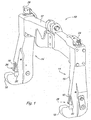
- Fig. 1 is a perspective view of a quick coupler embodying the invention
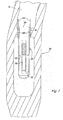
- Fig. 2 is a sectional view of a left leg of the quick coupler of Fig. 1;
- Fig. 3 is a perspective view of the latch of Fig. 1;
- Fig. 4 is another perspective view of the latch of Fig. 1;
- Fig. 5 is a perspective view of the trigger of Fig. 1;
- Fig. 6 is a perspective view of the spring of Fig. 1;
- Fig. 7 is a sectional view in the direction of lines 7 - 7 of Fig. 2;
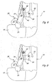
- Figs. 8-10 are side views showing the present invention in the process of receiving a hitch pin.
- a quick coupler 10 includes an inverted, generally U-shaped frame which has a transverse bight portion 12 and a pair of depending hollow legs 14.
- the legs 14 depend from the outer ends of bight 12 and are formed integrally therewith.
- the lower portions of legs 14 have rearwardly extending hooks 18, each of which forms an upwardly opening recess 20 which is adapted to receive the lower hitch pins 22 (shown in Fig. 2) of an associated implement (not shown).
- the hitch pins 22 are releasably held in the hook recesses 20 by the applicants' latching mechanism 26, operated by a known lever mechanism 28 positioned at the top of legs 14.
- a portion of the latching mechanism 26 projects outwardly through a latch aperture 16 in a rear wall 15 of the leg 14.
- the latching mechanism 26 includes a control bar 30 with an upper end coupled to the known lever mechanism 28. Control bar 30 is urged downwardly by spring 29. The lower end of the bar 30 includes a coupling member 32 through which extend a pair of coupling bores 34 and 36.
- the latching mechanism 26 also includes a latch 38 and a trigger 40.
- a stop pin 33 is mounted in a bore in the legs 14, spaced apart from and below coupling member 32.
- latch 38 is pivotally coupled to the leg 14 by a latch pivot pin 42 which extends laterally and horizontally through a pivot bore 44 in the upper end of latch 38.
- a trigger pivot bore 46 extends though a central portion of latch 38.
- Wall 15 is engagable with the latch 38 to prevent the latch from pivoting clockwise from the closed position shown in Fig. 2.
- the latch 38 includes a pair of spaced-apart side walls 48 and 50 which form a slot 52 therebetween.
- the lower end of latch 38 forms a wall 41 which extends part way between the side walls 48 and 50 and which forms a generally rearwardly facing wall or shoulder 43.
- the trigger 40 has a generally L-shaped structure with a first arm 54 and a second arm 56 projecting away from a central portion 58.
- a pivot bore 60 extends through central portion 58 and receives a pivot pin 61.
- the lower end of arm 56 forms a tab 62.
- the outer end of arm 54 forms a pair of spaced-apart legs 64 and 66 which are separated by a slot 68.
- a pivot pin bore 70 extends through legs 64 and 66.
- a stop recess or notch 72 is formed in a corner of legs 64 and 66.
- a latch spring 80 is mounted over latch 38.
- Spring 80 includes a transverse bight portion 82 and a pair of arms 84.
- Latch 38 is received between arms 84.
- Each arm 84 forms a coil or loop 86 which receives a corresponding end of pivot pin 42.
- the bight portion 82 engages and extends across a front side of the latch 38.
- the upper end of arms 84 engage an inner surface of rear wall 15 of leg 14.
- spring 80 is coupled to latch 38 and is biased to urge latch 38 clockwise, viewing Fig. 2, and thus, urges the lower end of latch 38 outwardly through opening 16 to its latched position shown in Fig. 2.
- the latch 38 is pivotally coupled to a wall of the leg 14 by pin 42.
- the trigger 40 extends through the slot 52 in latch 38 and is pivotally coupled to latch 38 by pin 61.
- Trigger 40 is also pivotally coupled to coupling member 32 by a pin received by bores 70 and 34.
- the surface of trigger notch 72 engages stop pin 33.
- stop pin 33 engages notch 72
- the arm 54 and pin 61 prevent latch 38 from pivoting counter-clockwise about pin 42 out of its latched or closed position to its open position.
- the hitch pin 22 is held within the hook recess 20 by latch 38.
- hitch pin 22 will first engage arm 56 or tab 62 of trigger 40. This pivots the trigger counter-clockwise about pin 61 and moves notch 72 out of engagement with stop pin 33 while the end of trigger arm 54 moves the control bar 30 upwardly against the bias of spring 29. The hitch pin 22 will then pivot latch 38 counter-clockwise about pin 42 to its open position wherein hitch pin 22 may be moved into the hook recess 20.
- the above quick coupler latch has both a locking capability and the ability to attach an implement without the latches being manually opened.
Landscapes
- Life Sciences & Earth Sciences (AREA)
- Engineering & Computer Science (AREA)
- Mechanical Engineering (AREA)
- Environmental Sciences (AREA)
- Zoology (AREA)
- Soil Sciences (AREA)
- Transportation (AREA)
- Buckles (AREA)
- Agricultural Machines (AREA)
- Lock And Its Accessories (AREA)
- Carriages For Children, Sleds, And Other Hand-Operated Vehicles (AREA)
- Quick-Acting Or Multi-Walled Pipe Joints (AREA)
- Hooks, Suction Cups, And Attachment By Adhesive Means (AREA)
Abstract
Description
- The present invention relates to an implement quick coupler latch mechanism.
- Implement quick couplers are used to improve the ease of attaching an implement to the 3-point hitch of a tractor. Typically, such couplers have a U-frame with lower hooks and with latches which capture the implement pins in the lower hooks. The latches are connected via a linkage to a handle near the top of the coupler frame. The operator can manipulate the handles to open the latches to allow the implement to be detached from the quick coupler.
- Most current quick couplers, including current production John Deere couplers include an L-shaped latch member. A spring on the linkage holds the linkage down, thus holding the latch in the closed position. This type of latch has an advantage in that the latches do not have to be opened prior to attaching the implement, because the implement pins can force the latches open as they enter the hooks. However, this style does not provide a positive lock on the latch to prevent it from being rotated to the open position as it relies on the force of the spring to counteract any outside forces on the latch.
- Another known production John Deere coupler has a straight latch and a 2-part column. The latch pivots at one end and the column is attached to a mid point of the latch. The linkage is attached to a center pin joint area of the 2-part column. When the latch is closed, the column members are in an over-center position and act as a solid member to resist compressive loads, thus locking the latch closed. When the handle pulls the linkage upward, the linkage buckles the column, pulling the latch open. This design provided a positive lock to hold the latch closed, however, the latches had to be manually opened using the handles prior to attaching an implement. If the implement pins struck the latches in the closed position, damage could result to the parts.
- In another known production John Deere coupler includes a similar column. In this design, one member of the column was roughly L-shaped and extended through the latch to provide a "trigger". This trigger allows the implement to be attached without manually opening the latches. The implement pins contact the trigger before they contact the latches themselves. As the pins push into the coupler, the trigger buckles the column and allows the latch to move to the open position. This design combined a locking feature with the ability to attach the implement to the coupler without first opening the latches. However, the column required many components and became somewhat complex.
- Accordingly, an object of this invention is to provide a quick coupler latch which has both a locking feature and the ability to attach an implement without the latches being manually opened. A quick coupler latch shall be provided, which especially is simple and has few components, thus reducing cost and assembly difficulty.
- These and other objects are achieved by the present invention, wherein a quick coupler has a frame with a hook, and an operator movable control bar supported by the frame. The hook has a hook recess therein for receiving a hitch pin. A latch mechanism includes a latch, a one-piece trigger, a spring, a stop fixed to the coupler frame, and a control bar. The latch is pivotally supported by the frame and is movable to an open position permitting the hitch pin to move into and out of the hook recess, and is movable to a closed position preventing removal of the hitch pin from the hook recess. The trigger is pivotally coupled only to the latch and to the control bar, and extends through a slot formed in the latch. The trigger is engagable with the hitch pin and operable to move the latch to the open position in response to movement of the hitch pin towards the recess. When the hitch pin is received by the hook recess, the stop engages the trigger to prevent the trigger from allowing the latch to move to its open position. An upper end of the latch is pivotally coupled to the coupler frame, and a central portion of the trigger is pivotally coupled to a central portion of the latch. A shoulder surface is formed in a lower end of the latch, and a tab projects from an end of the trigger. The tab is engagable with the shoulder surface to limit pivoting of the latch to its open position when the trigger is in engagement with the stop. A latch spring is mounted on the latch and engages the frame and biased to urge the latch to its closed position.
- For a complete understanding of the objects, techniques, and structure of the invention reference should be made to the following detailed description and accompanying drawings, wherein:
- Fig. 1 is a perspective view of a quick coupler embodying the invention;
- Fig. 2 is a sectional view of a left leg of the quick coupler of Fig. 1;
- Fig. 3 is a perspective view of the latch of Fig. 1;
- Fig. 4 is another perspective view of the latch of Fig. 1;
- Fig. 5 is a perspective view of the trigger of Fig. 1;
- Fig. 6 is a perspective view of the spring of Fig. 1;
- Fig. 7 is a sectional view in the direction of lines 7 - 7 of Fig. 2; and
- Figs. 8-10 are side views showing the present invention in the process of receiving a hitch pin.
- Referring to Fig. 1, a
quick coupler 10 includes an inverted, generally U-shaped frame which has atransverse bight portion 12 and a pair of dependinghollow legs 14. Thelegs 14 depend from the outer ends ofbight 12 and are formed integrally therewith. The lower portions oflegs 14 have rearwardly extendinghooks 18, each of which forms an upwardlyopening recess 20 which is adapted to receive the lower hitch pins 22 (shown in Fig. 2) of an associated implement (not shown). Thehitch pins 22 are releasably held in thehook recesses 20 by the applicants'latching mechanism 26, operated by aknown lever mechanism 28 positioned at the top oflegs 14. A portion of thelatching mechanism 26 projects outwardly through alatch aperture 16 in arear wall 15 of theleg 14. - As best seen in Fig. 2, the
latching mechanism 26 includes acontrol bar 30 with an upper end coupled to theknown lever mechanism 28.Control bar 30 is urged downwardly byspring 29. The lower end of thebar 30 includes acoupling member 32 through which extend a pair ofcoupling bores latching mechanism 26 also includes alatch 38 and atrigger 40. Astop pin 33 is mounted in a bore in thelegs 14, spaced apart from and belowcoupling member 32. - The upper end of
latch 38 is pivotally coupled to theleg 14 by alatch pivot pin 42 which extends laterally and horizontally through a pivot bore 44 in the upper end oflatch 38. Atrigger pivot bore 46 extends though a central portion oflatch 38.Wall 15 is engagable with thelatch 38 to prevent the latch from pivoting clockwise from the closed position shown in Fig. 2. As best seen in Figs. 3 and 4, thelatch 38 includes a pair of spaced-apart side walls slot 52 therebetween. The lower end oflatch 38 forms awall 41 which extends part way between theside walls shoulder 43. - Referring now to Figs. 2 and 5, the
trigger 40 has a generally L-shaped structure with afirst arm 54 and asecond arm 56 projecting away from acentral portion 58. Apivot bore 60 extends throughcentral portion 58 and receives apivot pin 61. The lower end ofarm 56 forms atab 62. The outer end ofarm 54 forms a pair of spaced-apart legs slot 68. Apivot pin bore 70 extends throughlegs legs - As best seen in Figs. 2, 6 and 7, a
latch spring 80 is mounted overlatch 38.Spring 80 includes atransverse bight portion 82 and a pair ofarms 84.Latch 38 is received betweenarms 84. Eacharm 84 forms a coil orloop 86 which receives a corresponding end ofpivot pin 42. Thebight portion 82 engages and extends across a front side of thelatch 38. The upper end ofarms 84 engage an inner surface ofrear wall 15 ofleg 14. As a result,spring 80 is coupled to latch 38 and is biased to urgelatch 38 clockwise, viewing Fig. 2, and thus, urges the lower end oflatch 38 outwardly throughopening 16 to its latched position shown in Fig. 2. - As best seen in Fig. 2, the
latch 38 is pivotally coupled to a wall of theleg 14 bypin 42. Thetrigger 40 extends through theslot 52 inlatch 38 and is pivotally coupled to latch 38 bypin 61.Trigger 40 is also pivotally coupled to couplingmember 32 by a pin received bybores trigger notch 72 engagesstop pin 33. Whenstop pin 33 engagesnotch 72, thearm 54 andpin 61 preventlatch 38 from pivoting counter-clockwise aboutpin 42 out of its latched or closed position to its open position. As a result, in the latched or closed position shown in Fig. 2, thehitch pin 22 is held within thehook recess 20 bylatch 38. - If it is desired to remove the
hitch pin 22 from thehook recess 20, the operator must use thelever 28 to raisecontrol bar 30 andcoupler 32. This pivots trigger 40 counter-clockwise, moves trigger 40 out of engagement withstop pin 33. Further raising ofcoupler 32causes tab 62 oftrigger 40 to engage wall orshoulder 43 oflatch 38, and thus further pivots latch 38 counter-clockwise aboutpivot pin 42 to its open position wherein thehitch pin 22 can be removed upwardly and out ofhook recess 20. - As best seen in Figs. 8 - 10, if no
hitch pin 22 is mounted in thehook recess 20, and thehitch pin 22 is moved towards thehook recess 20, thehitch pin 22 will first engagearm 56 ortab 62 oftrigger 40. This pivots the trigger counter-clockwise aboutpin 61 and moves notch 72 out of engagement withstop pin 33 while the end oftrigger arm 54 moves thecontrol bar 30 upwardly against the bias ofspring 29. Thehitch pin 22 will then pivotlatch 38 counter-clockwise aboutpin 42 to its open position whereinhitch pin 22 may be moved into thehook recess 20. - As a result, the above quick coupler latch has both a locking capability and the ability to attach an implement without the latches being manually opened.
- While the present invention has been described in conjunction with a specific embodiment, it is understood that many alternatives, modifications and variations will be apparent to those skilled in the art in light of the foregoing description. Accordingly, this invention is intended to embrace all such alternatives, modifications and variations which fall within the scope of the appended claims.
Claims (14)
- Latch mechanism for a quick coupler having a frame (12, 14) with a hook (18), and an operator movable control bar (30) supported by the frame (12, 14), the hook (18) having a hook recess (20) therein for receiving a hitch pin (22), the latch mechanism (26) comprising:a latch (38) pivotally supported by the frame (12, 14) and movable to an open position permitting the hitch pin (22) to move into and out of the hook recess (20), and movable to a closed position preventing removal of the hitch pin (22) from the hook recess (20);a stop (33) fixed to the coupler frame (12, 14); anda - preferably one-piece - trigger (40) pivotally coupled only to the latch (38) and to the control bar (30), the trigger (40) being engagable with the hitch pin (22) and operable to move the latch (38) to the open position in response to movement of the hitch pin (22) towards the recess (20), and when the hitch pin (22) is received by the hook recess (20), the stop (33) engaging the trigger (40) to prevent the trigger (40) from allowing the latch (38) to move to its open position.
- Latch mechanism of claim 1, wherein:
the trigger (40) extends through a slot (52) formed in the latch (38). - Latch mechanism of claim 1 or 2, wherein:an upper end of the latch (38) is pivotally coupled to the coupler frame (12, 14).
- Latch mechanism according to one of the claims 1 to 3, wherein:a central portion (58) of the trigger (40) is pivotally coupled to the latch (38), wherein preferably the central portion (58) of the trigger (40) is pivotally coupled to a central portion of the latch (38).
- Latch mechanism according to one of the claims 1 to 4, wherein:a shoulder surface (43) is formed in a lower end of the latch (38); anda tab (62) projects from an end of the trigger (40), the tab (62) being engagable with the shoulder surface (43) to limit pivoting of the latch (38) to its open position when the trigger (40) is in engagement with the stop (33).
- Latch mechanism according to one of the claims 1 to 5, further comprising:a latch spring (80) mounted on the latch (38) and engaging the frame (12, 14) and biased to urge the latch (38) to its closed position.
- Latch mechanism of claim 6, wherein:the latch spring (80) comprising a transverse bight portion (82) and a pair of arms (84), the latch (38) being received between arms (84).
- Latch mechanism of claim 6 or 7, wherein:the arms (84) have upper ends which engage an inner surface of the leg (14).
- Latch mechanism according to one of the claims 1 to 8, wherein:the trigger (40) comprises a generally L-shaped body with a central portion (58) pivotally coupled to the latch (38).
- Latch mechanism according to one of the claims 1 to 9, wherein:the trigger (40) comprises an end (72) engagable and disengagable with the stop (33).
- Latch mechanism according to one of the claims 1 to 10, wherein:the trigger (40) is pivotally coupled to the latch (38) by a pivot pin; andeach arm forms a loop (86) which receives the pivot pin (61), and the bight portion (82) engages and extends across a front side of the latch (38).
- Latch mechanism according to one of the claims 1 to 11, wherein:the trigger (40) has first and second arms (54, 56), the first arm (54) being coupled to a lower end of the control bar (30).
- Latch mechanism of claim 12, wherein:the second arm (56) being engagable with the hitch pin (22).
- A quick coupler having a frame (12, 14) with a hook (18), the hook (18) having hook recess (20) therein for receiving a hitch pin (22), the quick coupler having a latch mechanism (26) according to one of the claims 1 to 13.
Applications Claiming Priority (1)
| Application Number | Priority Date | Filing Date | Title |
|---|---|---|---|
| US11/222,621 US7530405B2 (en) | 2005-09-09 | 2005-09-09 | Implement quick coupler latch mechanism |
Publications (3)
| Publication Number | Publication Date |
|---|---|
| EP1762404A2 true EP1762404A2 (en) | 2007-03-14 |
| EP1762404A3 EP1762404A3 (en) | 2008-02-06 |
| EP1762404B1 EP1762404B1 (en) | 2011-03-23 |
Family
ID=37491692
Family Applications (1)
| Application Number | Title | Priority Date | Filing Date |
|---|---|---|---|
| EP06120430A Not-in-force EP1762404B1 (en) | 2005-09-09 | 2006-09-11 | Implement quick coupler latch mechanism |
Country Status (4)
| Country | Link |
|---|---|
| US (1) | US7530405B2 (en) |
| EP (1) | EP1762404B1 (en) |
| BR (1) | BRPI0603681A (en) |
| DE (1) | DE602006020816D1 (en) |
Cited By (5)
| Publication number | Priority date | Publication date | Assignee | Title |
|---|---|---|---|---|
| ITBO20090583A1 (en) * | 2009-09-15 | 2011-03-16 | Cbm Spa | PAIR OF HOOKS FOR THREE POINTS ATTACK |
| CN103004316A (en) * | 2012-12-06 | 2013-04-03 | 浙江乐客来机械有限公司 | Fast connecting device for tractor and matched agricultural implement |
| US9736976B2 (en) | 2014-11-07 | 2017-08-22 | Agco Corporation | Windrower with quick header attachment |
| WO2019026031A1 (en) | 2017-08-04 | 2019-02-07 | Wedgelock Equipment Limited | Quick coupler |
| US11702816B2 (en) | 2020-01-30 | 2023-07-18 | Wedgelock Equipment Limited | Quick coupler |
Families Citing this family (39)
| Publication number | Priority date | Publication date | Assignee | Title |
|---|---|---|---|---|
| DK1852555T3 (en) * | 2006-05-02 | 2012-10-08 | Kinshofer Gmbh | Security lock device for a quick release coupling |
| FI20070922L (en) * | 2007-11-29 | 2009-05-30 | Actioneco Oy | Fixing device and work machine where the fixing device is applied |
| DE202010016051U1 (en) * | 2010-12-02 | 2012-03-05 | Hans Sauermann | Coupling hook for a lower link of a tractor |
| US8925993B2 (en) | 2012-10-26 | 2015-01-06 | Denso International America, Inc. | Mounting feature to cross car beam |
| ES2557058B1 (en) * | 2015-09-29 | 2016-10-14 | Exel Industries | Device for connecting an agricultural accessory to a tractor agricultural vehicle |
| EP3439450A4 (en) | 2016-04-07 | 2019-12-25 | Mollick, Peter J. | SYSTEM FOR CONNECTING A TOOL TO MOBILE MACHINES |
| USD828028S1 (en) | 2017-06-12 | 2018-09-11 | Yeti Coolers, Llc | Container |
| USD869160S1 (en) | 2017-06-12 | 2019-12-10 | Yeti Coolers, Llc | Container |
| USD840150S1 (en) | 2017-06-12 | 2019-02-12 | Yeti Coolers, Llc | Container |
| USD872485S1 (en) | 2017-06-12 | 2020-01-14 | Yeti Coolers, Llc | Container |
| USD828029S1 (en) | 2017-06-12 | 2018-09-11 | Yeti Coolers, Llc | Container |
| US11976498B2 (en) | 2017-06-12 | 2024-05-07 | Yeti Coolers, Llc | Container and latching system |
| US12108853B2 (en) | 2019-01-06 | 2024-10-08 | Yeti Coolers, Llc | Luggage system |
| AU201717615S (en) | 2017-06-12 | 2018-01-15 | Yeti Coolers | Container |
| USD838983S1 (en) | 2017-06-12 | 2019-01-29 | Yeti Coolers, Llc | Container |
| USD872478S1 (en) | 2017-06-12 | 2020-01-14 | Yeti Coolers, Llc | Container |
| USD838984S1 (en) | 2017-06-12 | 2019-01-29 | Yeti Coolers, Llc | Container |
| WO2018231826A1 (en) | 2017-06-12 | 2018-12-20 | Yeti Coolers, Llc | Container and latching system |
| USD873020S1 (en) | 2017-06-12 | 2020-01-21 | Yeti Coolers, Llc | Container |
| US11685573B2 (en) | 2017-06-12 | 2023-06-27 | Yeti Coolers, Llc | Carry strap for container |
| EP3556546A1 (en) * | 2018-04-19 | 2019-10-23 | Heinz Bergmann e.Kfm. Maschinen für die Abfallwirtschaft | Mobile roller compressor and handling method |
| US11214936B2 (en) | 2018-07-10 | 2022-01-04 | Venture Products, Inc. | Power unit with salt spreader and salt spreader for use therewith |
| US20200015402A1 (en) * | 2018-07-12 | 2020-01-16 | Cnh Industrial America Llc | Mechanical stop for quick hitch latch engagement |
| US11477930B2 (en) | 2018-10-01 | 2022-10-25 | Vermeer Manufacturing Company | Three-point hitch mount systems |
| USD907445S1 (en) | 2018-12-11 | 2021-01-12 | Yeti Coolers, Llc | Container accessories |
| USD904829S1 (en) | 2018-12-11 | 2020-12-15 | Yeti Coolers, Llc | Container accessories |
| MX2021008199A (en) | 2019-01-06 | 2021-11-12 | Yeti Coolers Llc | LUGGAGE SYSTEM. |
| US12225993B2 (en) | 2019-01-06 | 2025-02-18 | Yeti Coolers, Llc | Luggage system |
| US11172614B2 (en) * | 2019-08-07 | 2021-11-16 | Cnh Industrial America Llc | Automatic header latch |
| CN111492738A (en) * | 2020-04-21 | 2020-08-07 | 福州荣林机械有限公司 | Quick connecting device for tractor and tillage implement |
| USD954436S1 (en) | 2020-06-30 | 2022-06-14 | Yeti Coolers, Llc | Luggage |
| USD951643S1 (en) | 2020-06-30 | 2022-05-17 | Yeti Coolers, Llc | Luggage |
| USD963344S1 (en) | 2020-06-30 | 2022-09-13 | Yeti Coolers, Llc | Luggage |
| USD961926S1 (en) | 2020-06-30 | 2022-08-30 | Yeti Coolers, Llc | Luggage |
| US12426543B2 (en) * | 2020-11-11 | 2025-09-30 | Techtronic Cordless Gp | Lawn mowers, detachable mower decks, and methods associated therewith |
| USD985937S1 (en) | 2020-12-16 | 2023-05-16 | Yeti Coolers, Llc | Container |
| USD994438S1 (en) | 2020-12-16 | 2023-08-08 | Yeti Coolers, Llc | Container |
| USD960648S1 (en) | 2020-12-16 | 2022-08-16 | Yeti Coolers, Llc | Container accessory |
| US20230062195A1 (en) * | 2021-08-31 | 2023-03-02 | Cnh Industrial America Llc | Quick coupler for a three-point hitch |
Family Cites Families (17)
| Publication number | Priority date | Publication date | Assignee | Title |
|---|---|---|---|---|
| US2979137A (en) | 1958-03-17 | 1961-04-11 | Deere & Co | Tractor-pickup hitch |
| US3172686A (en) * | 1963-05-28 | 1965-03-09 | Deere & Co | Coupler |
| US3531140A (en) * | 1968-01-26 | 1970-09-29 | Int Harvester Co | Tractor quick hitch attachment |
| US3807769A (en) * | 1972-09-25 | 1974-04-30 | Massey Ferguson Inc | Quick hitch attachment |
| US3829128A (en) * | 1972-12-22 | 1974-08-13 | Allis Chalmers | Quick hitch adapter |
| DE2618332C2 (en) * | 1976-04-27 | 1978-06-15 | Jean Walterscheid Gmbh, 5204 Lohmar | Coupling hook for a three-point linkage on agricultural tractors |
| GB1563457A (en) | 1977-11-09 | 1980-03-26 | Fiskars Ab Oy | Means for connecting implements to tractors |
| DE2832367C2 (en) * | 1978-07-22 | 1980-10-23 | Jean Walterscheid Gmbh, 5204 Lohmar | Coupling hook |
| US4415175A (en) * | 1982-06-23 | 1983-11-15 | Deere & Company | Coupler latch mechanism with a self-opening feature |
| US4549744A (en) | 1984-08-20 | 1985-10-29 | Deere & Company | Quick coupler latch |
| DE3912414C1 (en) * | 1989-04-15 | 1990-06-13 | Jean Walterscheid Gmbh, 5204 Lohmar, De | |
| US5244047A (en) | 1991-08-05 | 1993-09-14 | Arthur H. Groover | Apparatus for coupling implements to a farm tractor |
| DE4214569C2 (en) | 1992-05-08 | 2001-12-20 | Lehnhoff Hartstahl Gmbh & Co | Quick change device |
| DE4235780C1 (en) | 1992-10-23 | 1993-08-19 | Jean Walterscheid Gmbh, 5204 Lohmar, De | |
| DE4315811C1 (en) * | 1993-05-12 | 1995-01-19 | Walterscheid Gmbh Gkn | Coupling hook for the lower links of a three-point hitch of a tractor |
| US6349959B2 (en) * | 1999-05-07 | 2002-02-26 | Case Corporation | Warning device and method |
| GB0129814D0 (en) * | 2001-12-13 | 2002-01-30 | Gingerich Newton R | Operable latch |
-
2005
- 2005-09-09 US US11/222,621 patent/US7530405B2/en active Active
-
2006
- 2006-09-06 BR BRPI0603681-3A patent/BRPI0603681A/en not_active IP Right Cessation
- 2006-09-11 DE DE602006020816T patent/DE602006020816D1/en active Active
- 2006-09-11 EP EP06120430A patent/EP1762404B1/en not_active Not-in-force
Non-Patent Citations (1)
| Title |
|---|
| None |
Cited By (10)
| Publication number | Priority date | Publication date | Assignee | Title |
|---|---|---|---|---|
| ITBO20090583A1 (en) * | 2009-09-15 | 2011-03-16 | Cbm Spa | PAIR OF HOOKS FOR THREE POINTS ATTACK |
| EP2324691A2 (en) | 2009-09-15 | 2011-05-25 | CBM S.p.A. | Pair of hooks for three-point coupling |
| EP2324691A3 (en) * | 2009-09-15 | 2012-11-14 | CBM S.p.A. | Pair of hooks for three-point coupling |
| CN103004316A (en) * | 2012-12-06 | 2013-04-03 | 浙江乐客来机械有限公司 | Fast connecting device for tractor and matched agricultural implement |
| US9736976B2 (en) | 2014-11-07 | 2017-08-22 | Agco Corporation | Windrower with quick header attachment |
| WO2019026031A1 (en) | 2017-08-04 | 2019-02-07 | Wedgelock Equipment Limited | Quick coupler |
| EP3662112A4 (en) * | 2017-08-04 | 2021-04-28 | Wedgelock Equipment Limited | QUICK COUPLING |
| US11643787B2 (en) | 2017-08-04 | 2023-05-09 | Wedgelock Equipment Limited | Quick coupler |
| EP4265928A3 (en) * | 2017-08-04 | 2024-01-10 | Wedgelock Equipment Limited | Quick coupler |
| US11702816B2 (en) | 2020-01-30 | 2023-07-18 | Wedgelock Equipment Limited | Quick coupler |
Also Published As
| Publication number | Publication date |
|---|---|
| US7530405B2 (en) | 2009-05-12 |
| EP1762404B1 (en) | 2011-03-23 |
| EP1762404A3 (en) | 2008-02-06 |
| BRPI0603681A (en) | 2007-06-12 |
| DE602006020816D1 (en) | 2011-05-05 |
| US20070056754A1 (en) | 2007-03-15 |
Similar Documents
| Publication | Publication Date | Title |
|---|---|---|
| EP1762404B1 (en) | Implement quick coupler latch mechanism | |
| US4019753A (en) | Adjustable three-point tractor hitch | |
| US5263810A (en) | Working implement connection structure for a working vehicle having a boom assembly | |
| US11654734B2 (en) | Actuator coupler for hitch connection | |
| JP3978731B2 (en) | Agricultural tractor work equipment coupling device | |
| CA2308597A1 (en) | Hitch pin with locking lever | |
| US20020176772A1 (en) | Bucket fastener for a hydraulic shovel | |
| JPH0789310A (en) | Pintle hook type connection device | |
| US7364181B2 (en) | Self locking coupling device | |
| US3512804A (en) | Lock and hitch assembly | |
| US7478824B2 (en) | Drawbar hammer strap assembly with pin trigger | |
| JPH1179006A (en) | Fifth wheel coupling device | |
| AU651519B2 (en) | Integrated cam lever/handle lock fifth wheel | |
| PL194879B1 (en) | Fifth wheel coupler | |
| US4398745A (en) | Three point hitch lower link claw | |
| FI57036C (en) | KOPPLINGSKROK I SYNNERHET FOER ETT TREPUNKTSDRAGSYSTEM I EN TRAKTOR | |
| CA1242105A (en) | Quick coupler latch | |
| EP0994012A1 (en) | Fifth wheel release handle | |
| JPS598506A (en) | Latch mechanism of coupler | |
| US20240091965A1 (en) | Knife | |
| CA2524151C (en) | Self locking coupling device | |
| US6186532B1 (en) | Trailer coupler | |
| US8079614B1 (en) | Towmotor secondary lock | |
| US6224084B1 (en) | Trailer coupler | |
| JPH1085011A (en) | Elastic openable buckle |
Legal Events
| Date | Code | Title | Description |
|---|---|---|---|
| PUAI | Public reference made under article 153(3) epc to a published international application that has entered the european phase |
Free format text: ORIGINAL CODE: 0009012 |
|
| AK | Designated contracting states |
Kind code of ref document: A2 Designated state(s): AT BE BG CH CY CZ DE DK EE ES FI FR GB GR HU IE IS IT LI LT LU LV MC NL PL PT RO SE SI SK TR |
|
| AX | Request for extension of the european patent |
Extension state: AL BA HR MK YU |
|
| PUAL | Search report despatched |
Free format text: ORIGINAL CODE: 0009013 |
|
| AK | Designated contracting states |
Kind code of ref document: A3 Designated state(s): AT BE BG CH CY CZ DE DK EE ES FI FR GB GR HU IE IS IT LI LT LU LV MC NL PL PT RO SE SI SK TR |
|
| AX | Request for extension of the european patent |
Extension state: AL BA HR MK YU |
|
| 17P | Request for examination filed |
Effective date: 20080806 |
|
| AKX | Designation fees paid |
Designated state(s): DE FR GB IT |
|
| GRAP | Despatch of communication of intention to grant a patent |
Free format text: ORIGINAL CODE: EPIDOSNIGR1 |
|
| GRAS | Grant fee paid |
Free format text: ORIGINAL CODE: EPIDOSNIGR3 |
|
| GRAA | (expected) grant |
Free format text: ORIGINAL CODE: 0009210 |
|
| AK | Designated contracting states |
Kind code of ref document: B1 Designated state(s): DE FR GB IT |
|
| REG | Reference to a national code |
Ref country code: GB Ref legal event code: FG4D |
|
| REF | Corresponds to: |
Ref document number: 602006020816 Country of ref document: DE Date of ref document: 20110505 Kind code of ref document: P |
|
| REG | Reference to a national code |
Ref country code: DE Ref legal event code: R096 Ref document number: 602006020816 Country of ref document: DE Effective date: 20110505 |
|
| PLBE | No opposition filed within time limit |
Free format text: ORIGINAL CODE: 0009261 |
|
| STAA | Information on the status of an ep patent application or granted ep patent |
Free format text: STATUS: NO OPPOSITION FILED WITHIN TIME LIMIT |
|
| 26N | No opposition filed |
Effective date: 20111227 |
|
| REG | Reference to a national code |
Ref country code: DE Ref legal event code: R097 Ref document number: 602006020816 Country of ref document: DE Effective date: 20111227 |
|
| GBPC | Gb: european patent ceased through non-payment of renewal fee |
Effective date: 20110911 |
|
| PG25 | Lapsed in a contracting state [announced via postgrant information from national office to epo] |
Ref country code: IT Free format text: LAPSE BECAUSE OF FAILURE TO SUBMIT A TRANSLATION OF THE DESCRIPTION OR TO PAY THE FEE WITHIN THE PRESCRIBED TIME-LIMIT Effective date: 20110323 |
|
| REG | Reference to a national code |
Ref country code: FR Ref legal event code: ST Effective date: 20120531 |
|
| PG25 | Lapsed in a contracting state [announced via postgrant information from national office to epo] |
Ref country code: GB Free format text: LAPSE BECAUSE OF NON-PAYMENT OF DUE FEES Effective date: 20110911 Ref country code: FR Free format text: LAPSE BECAUSE OF NON-PAYMENT OF DUE FEES Effective date: 20110930 |
|
| PGFP | Annual fee paid to national office [announced via postgrant information from national office to epo] |
Ref country code: DE Payment date: 20210819 Year of fee payment: 16 |
|
| REG | Reference to a national code |
Ref country code: DE Ref legal event code: R119 Ref document number: 602006020816 Country of ref document: DE |
|
| PG25 | Lapsed in a contracting state [announced via postgrant information from national office to epo] |
Ref country code: DE Free format text: LAPSE BECAUSE OF NON-PAYMENT OF DUE FEES Effective date: 20230401 |