EP1760935B1 - A METHOD FOR SIGNALING INTERACTION OF ENSURING THE INTERNET PROTOCOL (IP) QUALITY OF SERVICE (QoS) - Google Patents
A METHOD FOR SIGNALING INTERACTION OF ENSURING THE INTERNET PROTOCOL (IP) QUALITY OF SERVICE (QoS) Download PDFInfo
- Publication number
- EP1760935B1 EP1760935B1 EP05771384A EP05771384A EP1760935B1 EP 1760935 B1 EP1760935 B1 EP 1760935B1 EP 05771384 A EP05771384 A EP 05771384A EP 05771384 A EP05771384 A EP 05771384A EP 1760935 B1 EP1760935 B1 EP 1760935B1
- Authority
- EP
- European Patent Office
- Prior art keywords
- source
- resources
- service stream
- user service
- control layer
- Prior art date
- Legal status (The legal status is an assumption and is not a legal conclusion. Google has not performed a legal analysis and makes no representation as to the accuracy of the status listed.)
- Expired - Lifetime
Links
Images



Classifications
-
- H—ELECTRICITY
- H04—ELECTRIC COMMUNICATION TECHNIQUE
- H04L—TRANSMISSION OF DIGITAL INFORMATION, e.g. TELEGRAPHIC COMMUNICATION
- H04L41/00—Arrangements for maintenance, administration or management of data switching networks, e.g. of packet switching networks
- H04L41/50—Network service management, e.g. ensuring proper service fulfilment according to agreements
- H04L41/5041—Network service management, e.g. ensuring proper service fulfilment according to agreements characterised by the time relationship between creation and deployment of a service
- H04L41/5054—Automatic deployment of services triggered by the service manager, e.g. service implementation by automatic configuration of network components
-
- H—ELECTRICITY
- H04—ELECTRIC COMMUNICATION TECHNIQUE
- H04L—TRANSMISSION OF DIGITAL INFORMATION, e.g. TELEGRAPHIC COMMUNICATION
- H04L12/00—Data switching networks
- H04L12/28—Data switching networks characterised by path configuration, e.g. LAN [Local Area Networks] or WAN [Wide Area Networks]
- H04L12/2854—Wide area networks, e.g. public data networks
- H04L12/2856—Access arrangements, e.g. Internet access
-
- H—ELECTRICITY
- H04—ELECTRIC COMMUNICATION TECHNIQUE
- H04L—TRANSMISSION OF DIGITAL INFORMATION, e.g. TELEGRAPHIC COMMUNICATION
- H04L47/00—Traffic control in data switching networks
- H04L47/70—Admission control; Resource allocation
-
- H—ELECTRICITY
- H04—ELECTRIC COMMUNICATION TECHNIQUE
- H04L—TRANSMISSION OF DIGITAL INFORMATION, e.g. TELEGRAPHIC COMMUNICATION
- H04L47/00—Traffic control in data switching networks
- H04L47/70—Admission control; Resource allocation
- H04L47/72—Admission control; Resource allocation using reservation actions during connection setup
- H04L47/724—Admission control; Resource allocation using reservation actions during connection setup at intermediate nodes, e.g. resource reservation protocol [RSVP]
-
- H—ELECTRICITY
- H04—ELECTRIC COMMUNICATION TECHNIQUE
- H04L—TRANSMISSION OF DIGITAL INFORMATION, e.g. TELEGRAPHIC COMMUNICATION
- H04L47/00—Traffic control in data switching networks
- H04L47/70—Admission control; Resource allocation
- H04L47/78—Architectures of resource allocation
- H04L47/783—Distributed allocation of resources, e.g. bandwidth brokers
- H04L47/785—Distributed allocation of resources, e.g. bandwidth brokers among multiple network domains, e.g. multilateral agreements
-
- H—ELECTRICITY
- H04—ELECTRIC COMMUNICATION TECHNIQUE
- H04L—TRANSMISSION OF DIGITAL INFORMATION, e.g. TELEGRAPHIC COMMUNICATION
- H04L47/00—Traffic control in data switching networks
- H04L47/70—Admission control; Resource allocation
- H04L47/80—Actions related to the user profile or the type of traffic
- H04L47/805—QOS or priority aware
Definitions
- the present invention relates to signalling exchange techniques, and more particularly, to a signalling exchange method for guaranteeing Internet Protocol (IP) Quality of Service (QoS).
- IP Internet Protocol
- QoS Quality of Service
- IP QoS IP QoS
- CM Call Manager
- a related document GB2386282 A describes a method for allocating shared resources in a packet data communications network.
- the allocation of shared transmission resources are optimized between two or more packet data streams executing in a device in a packet data communications network.
- the device includes a transmission resource manager function.
- Each application specifies a range of acceptable values for one or more of the parameters that determine the transmission quality of its data stream, and the transmission resource manager function allocates the available transmission resources to all the data streams in dependence on the range of acceptable values supplies by each application.
- An intelligent edge block is utilized for the digital media distribution, where the edge block couples to the communication network that transports the data streams carrying the digital multimedia data.
- the intelligent edge block joins point-to-multipoint transmission groups and receives a plurality of data streams in anticipation of the expected requirements of subscribers coupled to the edge block.
- the edge block Based on subscriber input relayed from subscribers coupled to the edge block, the edge block then provides the desired data streams to individual subscribers.
- the edge block may also maintain any bookkeeping information required to support the subscribers and perform the data distribution to the subscribers, which may include performing copying or multicast transmission support.
- Some embodiments of the present invention is to provide a signalling exchange method for guaranteeing IP QoS, so that the network based on the Diff-Serv model with an independent bearer control layer can determine a bearer path for a user service stream according to the signalling exchange scheme.
- IP Internet Protocol
- QoS Quality of Service
- the QoS resource request is a unidirectional resource request; and the process of the bearer control layer allocating resources for the user service stream includes: initiating the bearer control layer to perform upward resource allocation by a Call Manager (CM) of the source bearer network.
- CM Call Manager
- the method further includes: sending, by the source CM, the upward resources allocated by the bearer control layer to the source ER, and transferring a flow mapping command and a gating indication to the source ER; and in Step c, the process of the ER allocating a bearer path for the user service stream according to the allocated resources includes: upon receiving the flow mapping command, allocating by the source ER a bearer path for the user service stream according to the upward resources, and controlling the user service stream to pass through itself according to the gating indication.
- the QoS resource request includes: a gating indication; and in Step b, before the bearer control layer carrying out flow mapping for the ER, further including: the source CM on the bearer control layer transferring the upward resource allocation result to the CA, and after confirming that the upward resources have been allocated successfully, the CA sending an indication of initiating bearer resource reservation to the source CM; and after receiving the indication of initiating bearer resource reservation, the source CM sending the allocated upward resources to the source ER, and transferring a flow mapping command and a gating indication to the source ER; in Step c, the process of the ER allocating a bearer path for the user service stream according to the allocated resources includes: after receiving the flow mapping command, the source ER allocating a bearer path for the user service stream according to the upward resources, and controlling the user service stream to pass through itself according to the gating indication.
- the QoS resource request includes: a gating indication; and in Step b, the process of the bearer control layer carrying out flow mapping for the ER according to the resource allocation result includes: the source CM informing the upward resources allocated by the bearer control layer to the source ER, and transferring a flow mapping command and a gating indication to the source ER; in Step c, after the CA receives the execution result, the method further includes: transferring an indication of initiating service stream activation to the source CM, the source CM sending a gating indication to the source ER according to the indication of initiating service stream activation, and the source ER controlling the user service stream to pass through itself according to the gating indication.
- the QoS resource request is a bidirectional resource request; and in Step b, the process of the bearer control layer allocating resources for the user service stream includes: the source CM initiating upward resource allocation within the bearer control layer, and the destination CM initiating downward resource allocation within the bearer control layer.
- the QoS resource request is a bidirectional resource request; and in Step b, the process of the bearer control layer allocating resources for the user service stream includes: the source CM initiating both upward resource and downward resource allocation within the bearer control layer at the same time.
- Step b the process of the bearer control layer carrying out flow mapping for the ER according to the resource allocation result includes:
- the QoS resource request includes: a gating indication; and in Step b, before the bearer control layer carrying out flow mapping for the ER according to the resource allocation result, further includes: the source CM on the bearer control layer sending the resource allocation result to the CA, and after confirming that both the upward resources and downward resources are allocated successfully, the CA transferring an indication of initiating bearer resource reservation to the source CM; the process of the bearer control layer carrying out flow mapping for the ER comprising:
- the QoS resource request includes: a gating indication; and in Step b, the process of the bearer control layer carrying out flow mapping for the ER according to the resource allocation result includes:
- the process of transferring the execution result from the ER to the CA via the bearer control layer includes: the source ER transferring the execution result to the CA via the source CM of the bearer control layer.
- the method further includes: after transferring the user service stream via the bearer network, the CA initiating a close gating indication to the bearer control layer, the bearer control layer delivering the close gating indication to the ER, and the ER refusing the user service stream to pass through itself according to the close gating indication.
- the method further includes: the CA initiating an open gating indication to the bearer control layer, the bearer control layer delivering the open gating indication to the ER, and the ER allowing the user service stream to pass through itself according to the open gating indication.
- the QoS resource request contains a stream QoS parameter and information of a destination UA.
- the method further includes: after receiving the QoS resource request from the CA, determining, by the CM of the bearer control layer, whether the destination UA of the OoS resource request is within the management domain to which the source CM belongs.
- the Call Agent (CA) asks the bearer control layer to allocate resources. Then, flow mapping for an Edge Router (ER) is carried out according to the resource allocation result, and afterwards, the ER will allocate a bearer path for the user service stream. Thereby, an IP QoS signalling process for the user service stream is formed, which provides a convenience to allocate bearer paths for the network with an independent bearer control layer.
- CA Call Agent
- ER Edge Router
- the embodiments of the present invention provide a single-phase and a two-phase IP QoS signalling process.
- a flow mapping command will be sent to an ER without receiving an indication from the CA, and gating will be opened afterwards, whereas in the two-phase processing, after finishing resource allocation, the bearer control layer would not send a gating indication to an ER, unless an indication from the CA is received.
- the single-phase IP QoS signalling process could be adopted before transferring user service streams; and if charging should be strictly distinguished within an operator or among operators, or if operators have some special demands, the two-phase IP QoS signalling process provided in some embodiments of the present invention could be employed.
- the embodiments of the present invention allow the network to select a proper scheme according to different requirements, and thus it has higher adaptability.
- service streams are transferred via the bearer network, while information streams are transferred through the bearer control layer, ensuring the security and reliability of signalling transmission.
- the procedure of an embodiment of the invention includes: after receiving a request for transferring a user service stream, an SeCFE/SvCFE sends a QoS resource request to the bearer control layer; the bearer control layer allocates resources for the user service stream based on the received QoS resource request; a Switch Function Entity (SFE) carries out flow mapping based on the resources allocated by the bearer control layer, allocates a bearer path for the user service stream, and sends an execution result to the CA.
- the SeCFE/SvCFE may be a CA
- the SFE may be an ER.
- the bearer control layer may allocate resources for a unidirectional stream, or allocate resources for a bidirectional stream.
- the unidirectional stream is used for transferring a service stream sent from a source user
- the bidirectional stream is used for transferring a service stream from a source user and a service stream from a destination user. Therefore, some embodiments provide corresponding procedures for the above-mentioned two conditions, which are hereinafter described in detail with reference to the attached drawings and embodiments.
- either single-phase or two-phase processing is available. That is, in the single-phase processing, after resource allocation is finished, the bearer control layer directly sends a flow mapping command to the ER, and opens the gating without an indication from the CA; while in the two-phase processing, after finishing the resource allocation, the bearer control layer will not send a gating indication to the ER, unless an indication from the CA is received.
- the execution result from the source CM will include information of success; otherwise, if the source CM confirms that the allocation of the bearer path fails according to the execution result from the source ER, information of failure will be carried in the execution result from the source CM.
- the aforesaid is the procedure of single-phase IP QoS signalling process with unidirectional streams, and the two-phase IP QoS signalling process with unidirectional streams will be described hereinafter.
- the resource allocation result may contain either information of success or failure.
- Step 307 If the received resource allocation result contains information of success, the CA sends an indication to the source CM for initiating bearer resource reservation. If the result contains information of failure, end the procedure.
- Step 308 The source CM performs flow mapping for the source ER based on the indication and the information of upward resources received in Step 306, and sends a gating indication to the source ER.
- Step 309 The source ER performs flow mapping according to the gating indication sent from the source CM, allocates a bearer path for the user service stream, and allows the user service stream to pass through itself according to the gating indication, then returns an execution result to the source CM.
- Step 310 After the source CM receives the execution result from the source ER, the source CM transfers the execution result to the CA.
- the former has one more process of returning the information of upward resource allocation result from the source CM to the CA after finishing resource allocation.
- the resource allocation fails, it is not necessary for the CA to carry out subsequent processes. Only when the resource allocation succeeds would the CA send an indication of initiating bearer resource reservation to the source CM. Since the CA can decide whether to allow user service streams to pass through the ER according to demand, the charging point can be controlled accurately, and the bearer and control operations can be synchronized.
- Step 401 After receiving a request for transferring a user service stream from a source UA, a CA sends a QoS resource request containing stream QoS parameters, a gating indication and information of a destination UA to a source CM.
- Step 402 After the source CM receives the QoS resource request from the CA, the source CM determines whether the destination UA of the QoS resource request is within its management domain; if not, allocate upward resources of its domain for the user service stream, and transmit the QoS resource request to an intermediate CM; otherwise, allocate upward resources of its domain for the user service stream, and then go to Step 406.
- Step 403 After receiving the QoS resource request, the intermediate CM allocates upward resources of its domain for the user service stream, and then transmits the QoS resource request to the destination CM.
- Step 404 After receiving the QoS resource request, the destination CM allocates upward resources of its domain for the user service stream, and returns the allocated upward resources to the intermediate CM.
- Step 405 The intermediate CM combines the upward resources sent from the destination CM and the upward resources allocated by itself, and returns a combined upward resources to the source CM.
- Step 406 The source CM combines the upward resources sent from the intermediate CM and the upward resources allocated by itself, sends a combined upward resources to the source ER, and then transfers a flow mapping command to the source ER.
- Step 407 The source ER performs flow mapping according to the flow mapping command from the source CM, allocates a bearer path for the user service stream based on the upward resources sent from the source CM, and then returns an execution result to the source CM.
- Step 408 After the source CM receives the execution result from the source ER, the source CM sends the execution result to the CA.
- Step 409 If the execution result from the source CM contains information of success, the CA sends an indication of initiating service stream activation to the source CM for initiating service stream activation. If the result contains information of failure, end the procedure.
- Step 410 After the source CM receives the indication of initiating service stream activation, the source CM sends an open gating command to the source ER, so that user service streams could be allowed to pass through the source ER.
- a bidirectional stream can be separated into two unidirectional streams, i.e., an upward unidirectional stream and a downward unidirectional stream, with reference to operators' demand or according to other conditions. That is, resources of the two directions of bidirectional stream can be allocated respectively.
- the aforesaid processing for a unidirectional stream can be adopted.
- the resource allocation for an upward unidirectional stream is initiated by the source CM, while the resource allocation for a downward unidirectional stream is initiated by the destination CM.
- the destination CM initiates resource allocation after receiving a QoS resource request from the source CM, and then returns the resource allocation result to the source CM.
- the source CM confirms that both the upward resources and downward resources are successfully allocated, it returns information of success to the CA.
- upward and downward resources could be allocated uniformly, i.e., each CM may allocate the upward resources and downward resources at the same time.
- the situation that upward and downward resources are allocated together includes a single-phase processing and a two-phase processing, and the two-phase processing includes two cases of keeping resources on a CM or on an ER. Therefore, the procedures of these two cases are hereinafter described respectively.
- FIG. 5 illustrates the single-phase IP QoS signalling process with bidirectional streams, which includes:
- the QoS resource request should be a bidirectional resource request.
- Step 502 After receiving the QoS resource request from the CA, the source CM determines whether the destination UA of the QoS resource request is within its management domain. If it isn't within the source CM's management domain, allocate resources of its domain for the user service stream, where the allocated resources contain both upward resources for the upward stream and downward resources for the downward stream, and transmit the QoS resource request to an intermediate CM. Meanwhile, the source CM will inform the downward resources allocated by itself to the intermediate CM, and forward to Step 503. If it is within the source CM's management domain, after the upward resources and downward resources of the source CM's domain have been allocated for the user service stream, forward to Step 508.
- Step 503 Upon receiving the QoS resource request, the intermediate CM allocates both upward resources and downward resources within the intermediate CM's domain for the user service stream, combines both the downward resources sent from the source CM and the downward resources allocated by itself, and finally transfers the QoS resource request to the destination CM to inform a combined downward resources to the destination CM.
- Step 504 After receiving the bidirectional QoS resource request, the destination CM allocates both upward resources and downward resources within its domain for the user service stream, combines the downward resources sent from the intermediate CM and the downward resources allocated by itself, and then transfers a flow mapping command and a gating indication to the destination ER according to the combined downward resources, as well as sending the combined downward resources to the destination ER.
- the flow mapping command and the gating indication are transferred at the same time.
- Step 505 After receiving the flow mapping command and the gating indication, the destination ER allocates a bearer path for the user service stream, allows the user service stream to pass through itself, and then returns an execution result to the destination CM.
- Step 506 After receiving the execution result from the destination ER, the destination CM returns the upward resources allocated by itself to the intermediate CM.
- Step 507 The intermediate CM combines the upward resources sent from the destination CM and the upward resources allocated by itself, and then transfers a resource allocation result to the source CM.
- Step 508 The source CM combines the upward resources sent from the intermediate CM and the upward resources allocated by itself. If the upward resources are allocated successfully, the upward resources will be sent to the source ER, and a flow mapping command and a gating indication will be transferred to the source ER, as well.
- Step 509 The source ER performs flow mapping according to the flow mapping command, and allocates a bearer path for the user service stream according to the upward resources. Then, the source ER allows the user service stream to pass through itself based on the gating indication, and returns an execution result to the source CM.
- Step 510 After the source CM receives the execution result from the source ER, the source CM transfers the execution result to the CA.
- the above-mentioned is the single-phase IP QoS signalling process with bidirectional streams.
- the allocated resources can be kept either on a CM, or on an ER, where the former is illustrated on Figure 6 , and the latter is illustrated on Figure 7 .
- the procedure of keeping resources on a CM includes:
- the QoS resource request is a bidirectional resource request.
- Step 602 After receiving the QoS resource request from the CA, the source CM determines whether the destination UA of the QoS resource request is within its management domain. If it is within the source CM's management domain, allocate upward and downward resources of this domain for the user service stream, deliver the QoS resource request to an intermediate CM, and send the downward resources allocated by the source CM to the intermediate CM. Otherwise, allocate upward resources and downward resources of its domain for the user service stream, and then forward to Step 606.
- Step 603 After receiving the QoS resource request, the intermediate CM allocates both upward resources and downward resources within its domain for the user service stream, combines the downward resources sent from the source CM and the downward resources allocated by itself, and then delivers the QoS resource request to the destination CM and sends the combined downward resources to the destination CM.
- Step 604 After receiving the QoS resource request, the destination CM allocates both upward resources and downward resources within its domain for the user service stream, combines the downward resources sent from the intermediate CM and the downward resources allocated by itself, and then transfers the upward resources allocated by itself to the intermediate CM.
- Step 605 The intermediate CM combines the upward resources sent from the destination CM and the upward resources allocated by itself, and then returns a combined upward resources to the source CM.
- Step 606 The source CM combines the upward resources sent from the intermediate CM and the upward resources allocated by itself, and then returns a resource allocation result to the CA.
- Step 607 If information of success is contained in the resource allocation result, the CA sends an indication of initiating bearer resource reservation to the source CM for initiating bearer resource reservation.
- Steps 608 and 610 will be performed at the same time.
- Step 608 The source CM transfers a flow mapping command and a gating indication to the source ER based on both the indication of initiating bearer resource reservation from the CA and the upward resources allocated by the source CM itself, then forwards to Step 609.
- Step 609 The source ER carries out flow mapping according to the flow mapping command, allocates a bearer path for the user service stream according to the upward resources allocated by the bearer control layer, and allows the user service stream to pass through the source ER itself, and then transfers an execution result to the source CM, and forwards to Step 616.
- Steps 610 ⁇ 611 The source CM transfers the received indication of initiating bearer resource reservation to the destination CM via the intermediate CM.
- the source CM could directly transfer the received indication to the destination CM, not via the intermediate CM.
- Step 612 The destination CM transfers a flow mapping command and a gating indication to the destination ER according to the downward resources allocated by itself before.
- Step 613 The destination ER carries out flow mapping according to the flow mapping command, allocates a bearer path for the user service stream according to the downward resources, and allows the user service stream to pass through the destination ER itself, and then returns an execution result to the destination CM.
- Steps 614 ⁇ 615 The destination CM transfers the execution result to the source CM via the intermediate CM.
- the destination CM could directly transfer the execution result to the source CM, not via the intermediate CM.
- Step 616 The source CM transfers the execution result to the CA.
- Figure 7 illustrates the procedure of keeping resources on an ER, which includes:
- the QoS resource request is a bidirectional resource request.
- Step 702 After receiving the QoS resource request from the CA, the source CM determines whether the destination UA of the QoS resource request is within its management domain. If it is, allocate upward and downward resources within its domain for the user service stream, and deliver the QoS resource request to an intermediate CM. Otherwise, allocate upward and downward resources within its domain for the user service stream, then forward to Step 708.
- Step 703 After receiving the QoS resource request, the intermediate CM allocates both upward resources and downward resources of its domain for the user service stream, combines the downward resources sent from the source CM and the downward resources allocated by itself, and then delivers the QoS resource request to the destination CM, and transfers the combined downward resources to the destination CM.
- Step 704 After receiving the QoS resource request, the destination CM allocates both upward resources and downward resources within its domain for the user service stream, combines the downward resources sent from the intermediate CM and the downward resources allocated by itself, and then transfers a flow mapping command to the intermediate ER according to the combined downward resources.
- Step 705 After receiving the flow mapping command, the destination ER allocates a bearer path for the user service stream, and returns an execution result to the destination CM.
- Step 706 After receiving the execution result, the destination CM returns the upward resources allocated in advance to the intermediate CM.
- Step 707 The intermediate CM combines the upward resources sent from the destination CM and the upward resources allocated by itself, and then sends a combined upward resources to the source CM.
- Step 708 The source CM combines the upward resources sent from the intermediate CM and the upward resources allocated by itself. If the upward resources are allocated successfully, a flow mapping command will be transferred to the source ER according to the upward resources.
- Step 709 The source ER carries out flow mapping according to the flow mapping command, allocates a bearer path for the user service stream according to the upward resources, and returns an execution result to the source CM.
- Step 710 After receiving the execution result from the source ER, the source CM returns an execution result to the CA.
- Step 711 If the execution result contains information of success, the CA sends out an indication of initiating service stream activation to the source CM, in order to perform Steps 712 and 713 at the same time. If the execution result contains information of failure, end the procedure.
- Step 712 The source CM transfers an open gating indication to the source ER, allowing the user service stream to pass through itself.
- the user service stream can be born on the bearer resource allocated in advance via the source ER.
- Steps 713 ⁇ 714 The source CM transfers a gating indication to the destination CM via the intermediate CM.
- the source CM could directly transfer a gating indication to the destination CM, and not via the intermediate CM.
- Step 715 The destination CM transfers a gating indication to the destination ER, allowing the user service stream to pass through.
- user service streams can flow in bidirection.
- a user service stream can be transferred in the bearer network, i.e., a session between users can be set up.
- a CA can initiate a close or open gating indication at any moment if necessary. For example, if it is needed for the CA to end transferring the user service stream, the CA can send out a close gating indication. After the user service stream is closed, if it is needed to keep or restart the user service stream, the CA can send out an open gating indication to re-open the user service stream. This kind of indication is sent to the ER via the CM, and the ER may determine whether to allow the user service stream to pass through based on the open gating indication.
- the CA may transfer the open gating indication to the source CM, and the source CM delivers the open gating indication to the source ER.
- the source ER will determine whether to allow the user service stream to pass through according to the open gatirig indication.
- the source CM will transfer the open gating indication to both the source ER and the destination CM via the bearer control layer. Then, the destination CM delivers the open gating indication to the destination ER. Naturally, the source ER or the destination ER determines respectively whether to allow the user service stream to pass through itself according to the open gating indication.
Landscapes
- Engineering & Computer Science (AREA)
- Computer Networks & Wireless Communication (AREA)
- Signal Processing (AREA)
- Data Exchanges In Wide-Area Networks (AREA)
- Mobile Radio Communication Systems (AREA)
- Telephonic Communication Services (AREA)
- Communication Control (AREA)
Abstract
Description
- The present invention relates to signalling exchange techniques, and more particularly, to a signalling exchange method for guaranteeing Internet Protocol (IP) Quality of Service (QoS).
- With the scale-up of Internet, network services arise one after another, and advanced multimedia systems emerge in endlessly. Thus, the Internet needs to transfer multimedia services, such as services complying with File Transfer Protocol (FTP) which are of high burstiness, or services complying with Hypertext Transfer Protocol (HTTP) which contain image files. As to real time services in the network, which are relatively sensitive to network characteristics such as latency and jitter, transmission of FTP and HTTP services may have a great influence on them. Moreover, those multimedia services may occupy a great deal of bandwidth, which makes it difficult in the conventional network to reliably transfer some key services in need of guaranteed bandwidth.
- In view of the above, diversified QoS techniques are proposed, e.g., many service models and mechanisms have been set up by IETF. Among these QoS techniques, the most approbatory one by those skilled in the art is a scheme put forward by IETF, where an Int-Serv model is applied during the access to and/or at the edge of the network, and a Diff-Serv model is applied in the core area of the network. However, the Diff-Serv model of the scheme provides priority levels to guarantee QoS, so it is difficult to guarantee transmission reliability and effect of the whole network, although the scheme is of high channel availability in the network.
- In the process of allocating paths for user service streams, signal exchange of IP QoS is needed between a service control layer and a Call Manager (CM), as well as among CMs, so as to satisfy the conversation resource demand in each management domain, as well as determine the resource reservation mode according to requirements of operators. It can be seen that an IP QoS signaling process is important for guaranteeing QoS of the bearer network. However, there isn't any uniform IP QoS signalling process at present.
- A related document
GB2386282 A - Another related document
EP1119120 A2 describes a method an apparatus for digital multimedia distribution is presented. An intelligent edge block is utilized for the digital media distribution, where the edge block couples to the communication network that transports the data streams carrying the digital multimedia data. The intelligent edge block joins point-to-multipoint transmission groups and receives a plurality of data streams in anticipation of the expected requirements of subscribers coupled to the edge block. Based on subscriber input relayed from subscribers coupled to the edge block, the edge block then provides the desired data streams to individual subscribers. The edge block may also maintain any bookkeeping information required to support the subscribers and perform the data distribution to the subscribers, which may include performing copying or multicast transmission support. - Some embodiments of the present invention is to provide a signalling exchange method for guaranteeing IP QoS, so that the network based on the Diff-Serv model with an independent bearer control layer can determine a bearer path for a user service stream according to the signalling exchange scheme.
- A signalling exchange method for guaranteeing Internet Protocol (IP) Quality of Service (QoS), which is applicable for a network with an independent bearer control layer, including:
- upon receiving a request from a source User Agent (UA) for transferring a user service stream, sending, by a Call Agent (CA), a QoS resource request to the bearer control layer;
- allocating resources for the user service stream on the bearer control layer, and sending a flow mapping command to an Edge Router (ER) according to the resource allocation result;
- after receiving the flow mapping command, allocating, by the ER, a bearer path for the user service stream based on the allocated resources, and transferring an execution result to the CA via the bearer control layer.
- The QoS resource request is a unidirectional resource request; and
the process of the bearer control layer allocating resources for the user service stream includes: initiating the bearer control layer to perform upward resource allocation by a Call Manager (CM) of the source bearer network. - The method further includes: sending, by the source CM, the upward resources allocated by the bearer control layer to the source ER, and transferring a flow mapping command and a gating indication to the source ER; and
in Step c, the process of the ER allocating a bearer path for the user service stream according to the allocated resources includes: upon receiving the flow mapping command, allocating by the source ER a bearer path for the user service stream according to the upward resources, and controlling the user service stream to pass through itself according to the gating indication. - The QoS resource request includes: a gating indication; and
in Step b, before the bearer control layer carrying out flow mapping for the ER, further including: the source CM on the bearer control layer transferring the upward resource allocation result to the CA, and after confirming that the upward resources have been allocated successfully, the CA sending an indication of initiating bearer resource reservation to the source CM; and
after receiving the indication of initiating bearer resource reservation, the source CM sending the allocated upward resources to the source ER, and transferring a flow mapping command and a gating indication to the source ER;
in Step c, the process of the ER allocating a bearer path for the user service stream according to the allocated resources includes: after receiving the flow mapping command, the source ER allocating a bearer path for the user service stream according to the upward resources, and controlling the user service stream to pass through itself according to the gating indication. - The QoS resource request includes: a gating indication; and
in Step b, the process of the bearer control layer carrying out flow mapping for the ER according to the resource allocation result includes: the source CM informing the upward resources allocated by the bearer control layer to the source ER, and transferring a flow mapping command and a gating indication to the source ER;
in Step c, after the CA receives the execution result, the method further includes: transferring an indication of initiating service stream activation to the source CM, the source CM sending a gating indication to the source ER according to the indication of initiating service stream activation, and the source ER controlling the user service stream to pass through itself according to the gating indication. - The QoS resource request is a bidirectional resource request; and
in Step b, the process of the bearer control layer allocating resources for the user service stream includes: the source CM initiating upward resource allocation within the bearer control layer, and the destination CM initiating downward resource allocation within the bearer control layer. - The QoS resource request is a bidirectional resource request; and
in Step b, the process of the bearer control layer allocating resources for the user service stream includes: the source CM initiating both upward resource and downward resource allocation within the bearer control layer at the same time. - In Step b, the process of the bearer control layer carrying out flow mapping for the ER according to the resource allocation result includes:
- informing the downward resources allocated by the destination CM on the bearer control layer to the destination ER, and transferring a flow mapping command and a gating indication to the destination ER;
- sending the upward resources allocated by the source CM on the bearer control layer to the source ER, and transferring a flow mapping command and a gating indication to the source ER; and
- in Step c, the process of the ER allocating a bearer path for the user service stream according to the allocated resources includes:
- allocating, by the destination ER, a bearer path for the user service stream according to the downward resources, and controlling the user service stream to pass through the destination ER according to the gating indication;
- allocating, by the source ER, a bearer path for the user service stream according to the upward resources, and controlling the user service stream to pass through the source ER according to the gating indication.
- The QoS resource request includes: a gating indication; and
in Step b, before the bearer control layer carrying out flow mapping for the ER according to the resource allocation result, further includes: the source CM on the bearer control layer sending the resource allocation result to the CA, and after confirming that both the upward resources and downward resources are allocated successfully, the CA transferring an indication of initiating bearer resource reservation to the source CM;
the process of the bearer control layer carrying out flow mapping for the ER comprising: - after receiving the indication of initiating bearer resource reservation, the source CM sending the allocated upward resources to the source ER, and transferring a flow mapping command and a gating indication to the source ER;
- the source CM sending the allocated downward resources to the destination CM via the bearer control layer, and the destination CM transferring a flow mapping command and a gating indication to the destination ER; and
- in Step c, the process of the ER allocating a bearer path for the user service stream according to the resources allocated includes:
- after receiving the flow mapping command, the source ER allocating a bearer path for the user service stream according to the upward resources, and controlling the user service stream to pass through the ER itself according to the gating indication;
- after receiving the flow mapping command, the destination ER allocating a bearer path for the user service stream according to the downward resources, and controlling the user service stream to pass through the ER itself according to the gating indication.
- The QoS resource request includes: a gating indication; and
in Step b, the process of the bearer control layer carrying out flow mapping for the ER according to the resource allocation result includes: - the destination CM on the bearer control layer transferring the allocated downward resources to the destination ER, and transferring a flow mapping command and a gating indication to the destination ER;
- the source CM on the bearer control layer sending the allocated upward resources to the source ER, and transferring a flow mapping command and a gating indication to the source ER; and
- after the CA receives the execution result, the method further includes:
- transferring an indication of initiating service stream activation to the source CM, transferring by the source CM a gating indication to the source ER according to the activation indication, and the source ER controlling the user service stream to pass through itself according to the gating indication;
- transferring by the source CM the gating indication to the destination ER via the bearer control layer, and the destination ER controlling the user service stream to pass through itself according to the gating indication.
- The process of transferring the execution result from the ER to the CA via the bearer control layer includes: the source ER transferring the execution result to the CA via the source CM of the bearer control layer.
- The method further includes: after transferring the user service stream via the bearer network, the CA initiating a close gating indication to the bearer control layer, the bearer control layer delivering the close gating indication to the ER, and the ER refusing the user service stream to pass through itself according to the close gating indication.
- The method further includes: the CA initiating an open gating indication to the bearer control layer, the bearer control layer delivering the open gating indication to the ER, and the ER allowing the user service stream to pass through itself according to the open gating indication.
- The QoS resource request contains a stream QoS parameter and information of a destination UA.
- The method further includes: after receiving the QoS resource request from the CA, determining, by the CM of the bearer control layer, whether the destination UA of the OoS resource request is within the management domain to which the source CM belongs.
- According to some embodiments of the present invention, after receiving a request for transferring a user service stream, the Call Agent (CA) asks the bearer control layer to allocate resources. Then, flow mapping for an Edge Router (ER) is carried out according to the resource allocation result, and afterwards, the ER will allocate a bearer path for the user service stream. Thereby, an IP QoS signalling process for the user service stream is formed, which provides a convenience to allocate bearer paths for the network with an independent bearer control layer.
- Further, the embodiments of the present invention provide a single-phase and a two-phase IP QoS signalling process. In the single-phase processing, a flow mapping command will be sent to an ER without receiving an indication from the CA, and gating will be opened afterwards, whereas in the two-phase processing, after finishing resource allocation, the bearer control layer would not send a gating indication to an ER, unless an indication from the CA is received. Consequently, if other information exchanges are needed, or charging points are not strictly desired by operators, the single-phase IP QoS signalling process could be adopted before transferring user service streams; and if charging should be strictly distinguished within an operator or among operators, or if operators have some special demands, the two-phase IP QoS signalling process provided in some embodiments of the present invention could be employed. In other words, the embodiments of the present invention allow the network to select a proper scheme according to different requirements, and thus it has higher adaptability.
- Additionally, in the signalling process according to some embodiments of the present invention, service streams are transferred via the bearer network, while information streams are transferred through the bearer control layer, ensuring the security and reliability of signalling transmission.
-
-
Figure 1 is a schematic diagram illustrating the Diff-Serv model with an independent bearer control layer in prior art; -
Figure 2 is a flowchart of the single-phase IP QoS signalling process with unidirectional streams in an embodiment of the invention; -
Figure 3 is a flowchart of the two-phase IP QoS signalling process with unidirectional streams when resources are kept on a CM in an embodiment of the invention; -
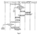
Figure 4 is a flowchart of the two-phase IP QoS signalling process with unidirectional streams when resources are kept on an ER in an embodiment of the invention; -
Figure 5 is a flowchart of the single-phase IP QoS signalling process with bidirectional streams in an embodiment of the invention; -
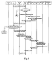
Figure 6 is a flowchart of the two-phase IP QoS signalling process with bidirectional streams when resources are kept on a CM in an embodiment of the invention; -
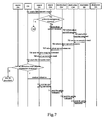
Figure 7 is a flowchart of the two-phase IP QoS signalling process with bidirectional streams when resources are kept on an ER in an embodiment of the invention. - The procedure of an embodiment of the invention includes: after receiving a request for transferring a user service stream, an SeCFE/SvCFE sends a QoS resource request to the bearer control layer; the bearer control layer allocates resources for the user service stream based on the received QoS resource request; a Switch Function Entity (SFE) carries out flow mapping based on the resources allocated by the bearer control layer, allocates a bearer path for the user service stream, and sends an execution result to the CA. Here, the SeCFE/SvCFE may be a CA, and the SFE may be an ER.
- In the process of allocating resources for user service streams, the bearer control layer may allocate resources for a unidirectional stream, or allocate resources for a bidirectional stream. Here, the unidirectional stream is used for transferring a service stream sent from a source user, and the bidirectional stream is used for transferring a service stream from a source user and a service stream from a destination user. Therefore, some embodiments provide corresponding procedures for the above-mentioned two conditions, which are hereinafter described in detail with reference to the attached drawings and embodiments.
- Firstly, the case of unidirectional stream is described.
- In the IP QoS signalling process with unidirectional streams, either single-phase or two-phase processing is available. That is, in the single-phase processing, after resource allocation is finished, the bearer control layer directly sends a flow mapping command to the ER, and opens the gating without an indication from the CA; while in the two-phase processing, after finishing the resource allocation, the bearer control layer will not send a gating indication to the ER, unless an indication from the CA is received.
- With reference to the flowchart shown in
Figure 2 , the single-phase IP QoS signalling process with unidirectional streams is described in detail, which includes: - Step 201: After a CA receives a request from a source User Agent (UA) for transferring a user service stream, the CA transfers a QoS resource request to a source CM, the QoS resource request containing stream QoS parameters and information of a destination UA.
- Step 202: After receiving the QoS resource request from the CA, the source CM determines whether the destination UA of the QoS resource request is within the management domain to which the source CM belongs; if not within the management domain, allocate upward resources of the management domain to which the source CM belongs to the user service stream, and transfer the QoS resource request to an intermediate CM, i.e., an intermediate BCFE; otherwise, allocate upward resources within the management domain to which the source CM belongs for the user service stream, and then forward to Step 206.
- Step 203: Upon receiving the QoS resource request, the intermediate CM allocates upward resources within the management domain to which the intermediate CM belongs for the user service stream, and then transmits the QoS resource request to the destination CM, i.e., the destination BCFE.
- Step 204: After receiving the QoS resource request, the destination CM allocates upward resources within the management domain to which the destination CM belongs for the user service stream, and then returns the upward resources to the intermediate CM.
- Step 205: The intermediate CM combines the upward resources sent from the destination CM and the upward resources allocated by itself, and sends a combined upward resources to the source CM. Here, combining the resources means overlaying different segments to form a path.
- Step 206: The source CM combines the upward resources sent from the intermediate CM and the upward resources allocated by itself, sends a combined upward resources to the source ER, i.e., the source SFE, and sends a flow mapping command and a gating indication to the source ER.
- Step 207: The source ER allocates a bearer path for the user service stream based on the flow mapping command and the information of upward resources sent from the source CM, allows the user service stream to pass through itself based on the gating indication from the source CM, and notifies an execution result to the source CM.
- Step 208: After receiving the execution result from the source ER, the source CM sends an execution result to the CA.
- If the source CM confirms, according to the execution result from the source ER, that the bearer path has been allocated successfully, the execution result from the source CM will include information of success; otherwise, if the source CM confirms that the allocation of the bearer path fails according to the execution result from the source ER, information of failure will be carried in the execution result from the source CM.
- The aforesaid is the procedure of single-phase IP QoS signalling process with unidirectional streams, and the two-phase IP QoS signalling process with unidirectional streams will be described hereinafter.
- In the two-phase processing, before a gating indication is transferred to the source ER, information of the allocated resources could be kept either on the source CM, or on the source ER. Hereinafter, with reference to
Figure 3 , the procedure of keeping resources on the CM in the two-phase IP QoS signalling process is firstly described, where the implementation process includes: - Step 301: Upon receiving a request from a source UA for transferring a user service stream, a CA sends a QoS resource request to a source CM, the QoS resource request containing stream QoS parameters, a gating indication and information of a destination UA.
- Step 302: Upon receiving the QoS resource request from the CA, the source CM determines whether the destination UA of the QoS resource request is within the management domain to which the source CM belongs; if not within the management domain, allocate upward resources of the source CM's domain for the user service stream, and transmit the QoS resource request to an intermediate CM; otherwise, allocate upward resources of the source CM's domain for the user service stream, and then forward to Step 306.
- Step 303: Upon receiving the QoS resource request, the intermediate CM allocates upward resources of its domain for the user service stream, and then transmits the QoS resource request to a destination CM.
- Step 304: Upon receiving the QoS resource request, the destination CM allocates upward resources of its domain for the user service stream, and informs the upward resources of the destination CM's domain to the intermediate CM.
- Step 305: The intermediate CM combines the upward resources sent from the destination CM and the upward resources allocated by the intermediate CM itself, and returns a combined upward resources to the source CM.
- Step 306: The source CM combines the upward resources sent from the intermediate CM and the upward resources allocated by itself, and returns a resource allocation result to the CA.
- The resource allocation result may contain either information of success or failure.
- Step 307: If the received resource allocation result contains information of success, the CA sends an indication to the source CM for initiating bearer resource reservation. If the result contains information of failure, end the procedure.
- Step 308: The source CM performs flow mapping for the source ER based on the indication and the information of upward resources received in
Step 306, and sends a gating indication to the source ER. - Step 309: The source ER performs flow mapping according to the gating indication sent from the source CM, allocates a bearer path for the user service stream, and allows the user service stream to pass through itself according to the gating indication, then returns an execution result to the source CM.
- Step 310: After the source CM receives the execution result from the source ER, the source CM transfers the execution result to the CA.
- Comparing the aforesaid processing with the single-phase processing shown in
Figure 4 , the former has one more process of returning the information of upward resource allocation result from the source CM to the CA after finishing resource allocation. However, if the resource allocation fails, it is not necessary for the CA to carry out subsequent processes. Only when the resource allocation succeeds would the CA send an indication of initiating bearer resource reservation to the source CM. Since the CA can decide whether to allow user service streams to pass through the ER according to demand, the charging point can be controlled accurately, and the bearer and control operations can be synchronized. - Referring to
Figure 4 , as to the two-phase IP QoS signalling process with unidirectional streams, where resources are kept on an ER, the accompanying steps may be implemented. - Step 401: After receiving a request for transferring a user service stream from a source UA, a CA sends a QoS resource request containing stream QoS parameters, a gating indication and information of a destination UA to a source CM.
- Step 402: After the source CM receives the QoS resource request from the CA, the source CM determines whether the destination UA of the QoS resource request is within its management domain; if not, allocate upward resources of its domain for the user service stream, and transmit the QoS resource request to an intermediate CM; otherwise, allocate upward resources of its domain for the user service stream, and then go to
Step 406. - Step 403: After receiving the QoS resource request, the intermediate CM allocates upward resources of its domain for the user service stream, and then transmits the QoS resource request to the destination CM.
- Step 404: After receiving the QoS resource request, the destination CM allocates upward resources of its domain for the user service stream, and returns the allocated upward resources to the intermediate CM.
- Step 405: The intermediate CM combines the upward resources sent from the destination CM and the upward resources allocated by itself, and returns a combined upward resources to the source CM.
- Step 406: The source CM combines the upward resources sent from the intermediate CM and the upward resources allocated by itself, sends a combined upward resources to the source ER, and then transfers a flow mapping command to the source ER.
- Step 407: The source ER performs flow mapping according to the flow mapping command from the source CM, allocates a bearer path for the user service stream based on the upward resources sent from the source CM, and then returns an execution result to the source CM.
- Step 408: After the source CM receives the execution result from the source ER, the source CM sends the execution result to the CA.
- Step 409: If the execution result from the source CM contains information of success, the CA sends an indication of initiating service stream activation to the source CM for initiating service stream activation. If the result contains information of failure, end the procedure.
- Step 410: After the source CM receives the indication of initiating service stream activation, the source CM sends an open gating command to the source ER, so that user service streams could be allowed to pass through the source ER.
- The above are scenarios about allocating resources for unidirectional streams. In scenarios of allocating resources for bidirectional streams, a bidirectional stream can be separated into two unidirectional streams, i.e., an upward unidirectional stream and a downward unidirectional stream, with reference to operators' demand or according to other conditions. That is, resources of the two directions of bidirectional stream can be allocated respectively. For each unidirectional stream, the aforesaid processing for a unidirectional stream can be adopted. The resource allocation for an upward unidirectional stream is initiated by the source CM, while the resource allocation for a downward unidirectional stream is initiated by the destination CM. In other words, the destination CM initiates resource allocation after receiving a QoS resource request from the source CM, and then returns the resource allocation result to the source CM. When the source CM confirms that both the upward resources and downward resources are successfully allocated, it returns information of success to the CA.
- Alternatively, in the allocation of bidirectional stream, upward and downward resources could be allocated uniformly, i.e., each CM may allocate the upward resources and downward resources at the same time. The situation that upward and downward resources are allocated together includes a single-phase processing and a two-phase processing, and the two-phase processing includes two cases of keeping resources on a CM or on an ER. Therefore, the procedures of these two cases are hereinafter described respectively.
-
Figure 5 illustrates the single-phase IP QoS signalling process with bidirectional streams, which includes: - Step 501: After receiving a request from a source UA for transferring a user service stream, a CA sends a QoS resource request to a source CM, the QoS resource request containing stream QoS parameters, a gating indication and information of a destination UA.
- The QoS resource request should be a bidirectional resource request.
- Step 502: After receiving the QoS resource request from the CA, the source CM determines whether the destination UA of the QoS resource request is within its management domain. If it isn't within the source CM's management domain, allocate resources of its domain for the user service stream, where the allocated resources contain both upward resources for the upward stream and downward resources for the downward stream, and transmit the QoS resource request to an intermediate CM. Meanwhile, the source CM will inform the downward resources allocated by itself to the intermediate CM, and forward to Step 503. If it is within the source CM's management domain, after the upward resources and downward resources of the source CM's domain have been allocated for the user service stream, forward to Step 508.
- Step 503: Upon receiving the QoS resource request, the intermediate CM allocates both upward resources and downward resources within the intermediate CM's domain for the user service stream, combines both the downward resources sent from the source CM and the downward resources allocated by itself, and finally transfers the QoS resource request to the destination CM to inform a combined downward resources to the destination CM.
- Step 504: After receiving the bidirectional QoS resource request, the destination CM allocates both upward resources and downward resources within its domain for the user service stream, combines the downward resources sent from the intermediate CM and the downward resources allocated by itself, and then transfers a flow mapping command and a gating indication to the destination ER according to the combined downward resources, as well as sending the combined downward resources to the destination ER.
- During the single-phase processing, the flow mapping command and the gating indication are transferred at the same time.
- Step 505: After receiving the flow mapping command and the gating indication, the destination ER allocates a bearer path for the user service stream, allows the user service stream to pass through itself, and then returns an execution result to the destination CM.
- Step 506: After receiving the execution result from the destination ER, the destination CM returns the upward resources allocated by itself to the intermediate CM.
- Step 507: The intermediate CM combines the upward resources sent from the destination CM and the upward resources allocated by itself, and then transfers a resource allocation result to the source CM.
- Step 508: The source CM combines the upward resources sent from the intermediate CM and the upward resources allocated by itself. If the upward resources are allocated successfully, the upward resources will be sent to the source ER, and a flow mapping command and a gating indication will be transferred to the source ER, as well.
- Step 509: The source ER performs flow mapping according to the flow mapping command, and allocates a bearer path for the user service stream according to the upward resources. Then, the source ER allows the user service stream to pass through itself based on the gating indication, and returns an execution result to the source CM.
- Step 510: After the source CM receives the execution result from the source ER, the source CM transfers the execution result to the CA.
- The above-mentioned is the single-phase IP QoS signalling process with bidirectional streams. As to the two-phase IP QoS signalling process with bidirectional streams, the allocated resources can be kept either on a CM, or on an ER, where the former is illustrated on
Figure 6 , and the latter is illustrated onFigure 7 . These two procedures are hereinafter described respectively. - As shown on
Figure 6 , the procedure of keeping resources on a CM includes: - Step 601: After receiving a request for transferring a user service stream from a source UA, a CA transfers a QoS resource request containing stream QoS parameters, a gating indication and information of a destination UA to the source CM.
- The QoS resource request is a bidirectional resource request.
- Step 602: After receiving the QoS resource request from the CA, the source CM determines whether the destination UA of the QoS resource request is within its management domain. If it is within the source CM's management domain, allocate upward and downward resources of this domain for the user service stream, deliver the QoS resource request to an intermediate CM, and send the downward resources allocated by the source CM to the intermediate CM. Otherwise, allocate upward resources and downward resources of its domain for the user service stream, and then forward to Step 606.
- Step 603: After receiving the QoS resource request, the intermediate CM allocates both upward resources and downward resources within its domain for the user service stream, combines the downward resources sent from the source CM and the downward resources allocated by itself, and then delivers the QoS resource request to the destination CM and sends the combined downward resources to the destination CM.
- Step 604: After receiving the QoS resource request, the destination CM allocates both upward resources and downward resources within its domain for the user service stream, combines the downward resources sent from the intermediate CM and the downward resources allocated by itself, and then transfers the upward resources allocated by itself to the intermediate CM.
- Step 605: The intermediate CM combines the upward resources sent from the destination CM and the upward resources allocated by itself, and then returns a combined upward resources to the source CM.
- Step 606: The source CM combines the upward resources sent from the intermediate CM and the upward resources allocated by itself, and then returns a resource allocation result to the CA.
- Step 607: If information of success is contained in the resource allocation result, the CA sends an indication of initiating bearer resource reservation to the source CM for initiating bearer resource reservation. When the source CM receives the indication from the CA, Steps 608 and 610 will be performed at the same time.
- Step 608: The source CM transfers a flow mapping command and a gating indication to the source ER based on both the indication of initiating bearer resource reservation from the CA and the upward resources allocated by the source CM itself, then forwards to Step 609.
- Step 609: The source ER carries out flow mapping according to the flow mapping command, allocates a bearer path for the user service stream according to the upward resources allocated by the bearer control layer, and allows the user service stream to pass through the source ER itself, and then transfers an execution result to the source CM, and forwards to Step 616.
-
Steps 610∼611: The source CM transfers the received indication of initiating bearer resource reservation to the destination CM via the intermediate CM. - Actually, the source CM could directly transfer the received indication to the destination CM, not via the intermediate CM.
- Step 612: The destination CM transfers a flow mapping command and a gating indication to the destination ER according to the downward resources allocated by itself before.
- Step 613: The destination ER carries out flow mapping according to the flow mapping command, allocates a bearer path for the user service stream according to the downward resources, and allows the user service stream to pass through the destination ER itself, and then returns an execution result to the destination CM.
-
Steps 614∼615: The destination CM transfers the execution result to the source CM via the intermediate CM. - Similarly, the destination CM could directly transfer the execution result to the source CM, not via the intermediate CM.
- Step 616: The source CM transfers the execution result to the CA.
-
Figure 7 illustrates the procedure of keeping resources on an ER, which includes: - Step 701: After receiving a request for transferring a user service stream from a source UA, a CA transfers a QoS resource request containing stream QoS parameters, a gating indication and information of a destination UA to the source CM.
- The QoS resource request is a bidirectional resource request.
- Step 702: After receiving the QoS resource request from the CA, the source CM determines whether the destination UA of the QoS resource request is within its management domain. If it is, allocate upward and downward resources within its domain for the user service stream, and deliver the QoS resource request to an intermediate CM. Otherwise, allocate upward and downward resources within its domain for the user service stream, then forward to Step 708.
- Step 703: After receiving the QoS resource request, the intermediate CM allocates both upward resources and downward resources of its domain for the user service stream, combines the downward resources sent from the source CM and the downward resources allocated by itself, and then delivers the QoS resource request to the destination CM, and transfers the combined downward resources to the destination CM.
- Step 704: After receiving the QoS resource request, the destination CM allocates both upward resources and downward resources within its domain for the user service stream, combines the downward resources sent from the intermediate CM and the downward resources allocated by itself, and then transfers a flow mapping command to the intermediate ER according to the combined downward resources.
- Step 705: After receiving the flow mapping command, the destination ER allocates a bearer path for the user service stream, and returns an execution result to the destination CM.
- Step 706: After receiving the execution result, the destination CM returns the upward resources allocated in advance to the intermediate CM.
- Step 707: The intermediate CM combines the upward resources sent from the destination CM and the upward resources allocated by itself, and then sends a combined upward resources to the source CM.
- Step 708: The source CM combines the upward resources sent from the intermediate CM and the upward resources allocated by itself. If the upward resources are allocated successfully, a flow mapping command will be transferred to the source ER according to the upward resources.
- Step 709: The source ER carries out flow mapping according to the flow mapping command, allocates a bearer path for the user service stream according to the upward resources, and returns an execution result to the source CM.
- Step 710: After receiving the execution result from the source ER, the source CM returns an execution result to the CA.
- Step 711: If the execution result contains information of success, the CA sends out an indication of initiating service stream activation to the source CM, in order to perform
Steps - Step 712: The source CM transfers an open gating indication to the source ER, allowing the user service stream to pass through itself.
- Thus, the user service stream can be born on the bearer resource allocated in advance via the source ER.
-
Steps 713∼714: The source CM transfers a gating indication to the destination CM via the intermediate CM. - Actually, the source CM could directly transfer a gating indication to the destination CM, and not via the intermediate CM.
- Step 715: The destination CM transfers a gating indication to the destination ER, allowing the user service stream to pass through.
- Via the above-mentioned procedures, user service streams can flow in bidirection.
- For the situation that the bearer control layer allocates upward resources and downward resources respectively, after finishing resource allocation, subsequent processes are similar to the process in which upward and downward resources are allocated uniformly.
- After a bearer path is allocated with any of the above procedures, a user service stream can be transferred in the bearer network, i.e., a session between users can be set up. However, after the session has been set up, a CA can initiate a close or open gating indication at any moment if necessary. For example, if it is needed for the CA to end transferring the user service stream, the CA can send out a close gating indication. After the user service stream is closed, if it is needed to keep or restart the user service stream, the CA can send out an open gating indication to re-open the user service stream. This kind of indication is sent to the ER via the CM, and the ER may determine whether to allow the user service stream to pass through based on the open gating indication.
- Specifically, if the user service stream is unidirectional, the CA may transfer the open gating indication to the source CM, and the source CM delivers the open gating indication to the source ER. The source ER will determine whether to allow the user service stream to pass through according to the open gatirig indication.
- If the user service stream is bidirectional, after the CA transfers the open gating indication to the source CM, the source CM will transfer the open gating indication to both the source ER and the destination CM via the bearer control layer. Then, the destination CM delivers the open gating indication to the destination ER. Naturally, the source ER or the destination ER determines respectively whether to allow the user service stream to pass through itself according to the open gating indication.
- To sum up, the foregoing is only preferred embodiments of the invention, and it is not used for limiting the protection scope thereof.
Claims (15)
- A signalling exchange method for guaranteeing Internet Protocol (IP) Quality of Service (QoS), which is applicable for a network with an independent bearer control layer, comprising:upon receiving a request from a source User Agent (UA) for transferring a user service stream, sending (201, 301, 401, 501, 601, 701), by a Call Agent (CA), a QoS resource request to the bearer control layer;allocating (202∼206, 302∼307, 402∼405, 502∼508, 602∼607, 702∼708) resources for the user service stream on the bearer control layer, and sending (206, 308, 406, 508, 608, 708) a flow mapping command to an Edge Router (ER) according to the resource allocation result;after receiving the flow mapping command, allocating (207, 309, 407, 509, 609, 709), by the ER, a bearer path for the user service stream based on the allocated resources, and transferring an execution result to the CA via the bearer control layer.
- The method according to Claim 1, wherein the QoS resource request is a unidirectional resource request; and
the process of the bearer control layer allocating resources for the user service stream comprises: initiating (202, 302, 402) the bearer control layer to perform upward resource allocation by a Call Manager (CM) of the source bearer network. - The method according to Claim 2, further comprising: sending (206, 308, 406), by the source CM, the upward resources allocated by the bearer control layer to the source ER, and transferring (206, 308, 406) a flow mapping command and a gating indication to the source ER; and
the process of the ER allocating a bearer path for the user service stream according to the allocated resources comprises: upon receiving the flow mapping command, allocating (207, 309, 407) by the source ER a bearer path for the user service stream according to the upward resources, and controlling the user service stream to pass through itself according to the gating indication. - The method according to Claim 2, wherein the QoS resource request comprises: a gating indication; and
the method further comprises: the source CM on the bearer control layer transferring (306) the upward resource allocation result to the CA, and after confirming that the upward resources have been allocated successfully, the CA sending (307) an indication of initiating bearer resource reservation to the source CM; and
after receiving the indication of initiating bearer resource reservation, the source CM sending (308) the allocated upward resources to the source ER, and transferring a flow mapping command and a gating indication to the source ER;
the process of the ER allocating a bearer path for the user service stream according to the allocated resources comprises: after receiving the flow mapping command, the source ER allocating (309) a bearer path for the user service stream according to the upward resources, and controlling the user service stream to pass through itself according to the gating indication. - The method according to Claim 2, wherein the QoS resource request comprises: a gating indication; and
the method further comprises: the source CM informing (206, 406) the upward resources allocated by the bearer control layer to the source ER, and transferring a flow mapping command and a gating indication to the source ER; and
after the CA receives the execution result, the method further comprises: transferring (409) an indication of initiating service stream activation to the source CM, the source CM sending a gating indication to the source ER according to the indication of initiating service stream activation, and the source ER controlling the user service stream to pass through itself according to the gating indication. - The method according to Claim 1, wherein the QoS resource request is a bidirectional resource request; and
the process of the bearer control layer allocating resources for the user service stream comprises: the source CM initiating upward resource allocation within the bearer control layer, and the destination CM initiating downward resource allocation within the bearer control layer. - The method according to Claim 1, wherein the QoS resource request is a bidirectional resource request; and
the process of the bearer control layer allocating resources for the user service stream comprises: the source CM initiating both upward resource and downward resource allocation within the bearer control layer at the same time. - The method according to Claim 6 or 7, further comprising:informing (504, 612, 704) the downward resources allocated by the destination CM on the bearer control layer to the destination ER, and transferring a flow mapping command and a gating indication to the destination ER;sending (508, 608, 708) the upward resources allocated by the source CM on the bearer control layer to the source ER, and transferring a flow mapping command and a gating indication to the source ER; andthe process of the ER allocating a bearer path for the user service stream according to the allocated resources comprises:allocating (505, 613, 705), by the destination ER, a bearer path for the user service stream according to the downward resources, and controlling the user service stream to pass through the destination ER according to the gating indication;allocating (509, 609, 709), by the source ER, a bearer path for the user service stream according to the upward resources, and controlling the user service stream to pass through the source ER according to the gating indication.
- The method according to Claim 6 or 7, wherein the QoS resource request comprises: a gating indication; and
the method further comprises: the source CM on the bearer control layer sending (606) the resource allocation result to the CA, and after confirming that both the upward resources and downward resources are allocated successfully, the CA transferring (607) an indication of initiating bearer resource reservation to the source CM;
after receiving the indication of initiating bearer resource reservation, the source CM sending (608) the allocated upward resources to the source ER, and transferring a flow mapping command and a gating indication to the source ER;
the source CM sending (610∼611) the allocated downward resources to the destination CM via the bearer control layer, and the destination CM transferring (612) a flow mapping command and a gating indication to the destination ER; and
the process of the ER allocating a bearer path for the user service stream according to the resources allocated comprises:after receiving the flow mapping command, the source ER allocating (609) a bearer path for the user service stream according to the upward resources, and controlling the user service stream to pass through the ER itself according to the gating indication;after receiving the flow mapping command, the destination ER allocating (613) a bearer path for the user service stream according to the downward resources, and controlling the user service stream to pass through the ER itself according to the gating indication. - The method according to Claim 6 or 7, wherein the QoS resource request comprises: a gating indication; and
the method further comprises:the destination CM on the bearer control layer transferring (704) the allocated downward resources to the destination ER, and transferring a flow mapping command and a gating indication to the destination ER;the source CM on the bearer control layer sending (708) the allocated upward resources to the source ER, and transferring a flow mapping command and a gating indication to the source ER; andafter the CA receives the execution result, the method further comprises:transferring (711) an indication of initiating service stream activation to the source CM, transferring (712) by the source CM a gating indication to the source ER according to the activation indication, and the source ER controlling the user service stream to pass through itself according to the gating indication;transferring (713∼715) by the source CM the gating indication to the destination ER via the bearer control layer, and the destination ER controlling the user service stream to pass through itself according to the gating indication. - The method according to Claim 1, wherein the process of transferring the execution result from the ER to the CA via the bearer control layer comprises: the source ER transferring the execution result to the CA via the source CM of the bearer control layer.
- The method according to Claim 1, further comprising: after transferring the user service stream via the bearer network, the CA initiating a close gating indication to the bearer control layer, the bearer control layer delivering the close gating indication to the ER, and the ER refusing the user service stream to pass through itself according to the close gating indication.
- The method according to Claim 12, further comprising: the CA initiating an open gating indication to the bearer control layer, the bearer control layer delivering the open gating indication to the ER, and the ER allowing the user service stream to pass through itself according to the open gating indication.
- The method according to Claim 1, wherein the QoS resource request contains a stream QoS parameter and information of a destination UA.
- The method according to Claim 14, _further comprising: after receiving the QoS resource request from the CA, determining (202, 302, 402, 502, 602, 702), by the CM of the bearer control layer, whether the destination UA of the OoS resource request is within the management domain to which the source CM belongs.
Applications Claiming Priority (2)
| Application Number | Priority Date | Filing Date | Title |
|---|---|---|---|
| CNB2004100704006A CN100514961C (en) | 2004-08-02 | 2004-08-02 | Signaling interactive method for Internet protocol service mass |
| PCT/CN2005/001177 WO2006012794A1 (en) | 2004-08-02 | 2005-08-02 | A METHOD FOR SIGNALING INTERACTION OF ENSURING THE INTERNET PROTOCOL (IP) QUALITY OF SERVICE (QoS) |
Publications (3)
| Publication Number | Publication Date |
|---|---|
| EP1760935A1 EP1760935A1 (en) | 2007-03-07 |
| EP1760935A4 EP1760935A4 (en) | 2010-05-05 |
| EP1760935B1 true EP1760935B1 (en) | 2010-10-13 |
Family
ID=35786875
Family Applications (1)
| Application Number | Title | Priority Date | Filing Date |
|---|---|---|---|
| EP05771384A Expired - Lifetime EP1760935B1 (en) | 2004-08-02 | 2005-08-02 | A METHOD FOR SIGNALING INTERACTION OF ENSURING THE INTERNET PROTOCOL (IP) QUALITY OF SERVICE (QoS) |
Country Status (7)
| Country | Link |
|---|---|
| US (1) | US7751349B2 (en) |
| EP (1) | EP1760935B1 (en) |
| JP (1) | JP4701246B2 (en) |
| CN (1) | CN100514961C (en) |
| AT (1) | ATE484900T1 (en) |
| DE (1) | DE602005024135D1 (en) |
| WO (1) | WO2006012794A1 (en) |
Families Citing this family (8)
| Publication number | Priority date | Publication date | Assignee | Title |
|---|---|---|---|---|
| KR100684177B1 (en) * | 2005-11-22 | 2007-02-20 | 한국전자통신연구원 | Method and apparatus for guaranteeing security through end-to-end CAC in Internet service network |
| FI20051320A0 (en) | 2005-12-22 | 2005-12-22 | Nokia Corp | Method of assigning packet flows to transmission paths in a communication system |
| CN101047950B (en) * | 2006-03-27 | 2010-05-12 | 华为技术有限公司 | Method for configuring default bearer in 3GPP evolved network |
| US8849297B2 (en) * | 2006-07-14 | 2014-09-30 | Qualcomm Incorporated | Call establishment and maintenance in a wireless network |
| CN102546370B (en) * | 2010-12-20 | 2015-07-29 | 华为技术有限公司 | service flow modification processing method, device and system |
| US20150271541A1 (en) | 2014-03-19 | 2015-09-24 | Time Warner Cable Enterprises Llc | Apparatus and methods for recording a media stream |
| US10375452B2 (en) | 2015-04-14 | 2019-08-06 | Time Warner Cable Enterprises Llc | Apparatus and methods for thumbnail generation |
| US10958948B2 (en) | 2017-08-29 | 2021-03-23 | Charter Communications Operating, Llc | Apparatus and methods for latency reduction in digital content switching operations |
Family Cites Families (18)
| Publication number | Priority date | Publication date | Assignee | Title |
|---|---|---|---|---|
| US5440563A (en) * | 1993-10-12 | 1995-08-08 | At&T Corp. | Service circuit allocation in large networks |
| US6631435B1 (en) * | 1996-02-02 | 2003-10-07 | Sony Corporation | Application programming interface for data transfer and bus management over a bus structure |
| US7376710B1 (en) * | 1999-10-29 | 2008-05-20 | Nortel Networks Limited | Methods and systems for providing access to stored audio data over a network |
| JP2001156838A (en) * | 1999-11-25 | 2001-06-08 | Nippon Telegr & Teleph Corp <Ntt> | Communication resource reservation method and apparatus, and recording medium recording communication resource reservation program |
| EP1119120A3 (en) | 1999-12-27 | 2006-03-29 | Alcatel Canada Inc. | Method and apparatus for distribution of multimedia data |
| US7180889B1 (en) * | 1999-12-30 | 2007-02-20 | At&T Corp. | Personal control of address assignment and greeting options for multiple BRG ports |
| US7068624B1 (en) * | 2000-02-25 | 2006-06-27 | Cisco Technology, Inc. | Wireless router and method for processing traffic in a wireless communications network |
| JP4536990B2 (en) * | 2000-05-22 | 2010-09-01 | テレフオンアクチーボラゲット エル エム エリクソン(パブル) | Application impact policy |
| EP1206067A1 (en) * | 2000-11-06 | 2002-05-15 | Agilent Technologies, Inc. (a Delaware corporation) | Method of and apparatus for network measurement |
| JP3578209B2 (en) * | 2000-11-20 | 2004-10-20 | 日本電気株式会社 | QoS server and resource allocation control method |
| JP2002314587A (en) * | 2001-04-17 | 2002-10-25 | Hitachi Ltd | Route setting method, route setting service method, network route management system, and network support system |
| JP2002374286A (en) * | 2001-06-13 | 2002-12-26 | Hitachi Ltd | Communication quality control system and communication quality control method |
| US20030093526A1 (en) * | 2001-11-13 | 2003-05-15 | Koninklijke Philips Electronics N. V. | Apparatus and method for providing quality of service signaling for wireless mac layer |
| CN1173500C (en) * | 2001-12-05 | 2004-10-27 | 华为技术有限公司 | Method for supporting services with different quality of service in high-speed downlink data packet access system |
| GB2386282A (en) * | 2002-03-05 | 2003-09-10 | Pa Consulting Services | Allocating shared resources in a packet data communications network |
| US7068600B2 (en) * | 2002-04-29 | 2006-06-27 | Harris Corporation | Traffic policing in a mobile ad hoc network |
| US7206324B2 (en) * | 2002-05-03 | 2007-04-17 | Telefonaktiebolaget Lm Ericsson (Publ) | QoS translator |
| EP1365545A1 (en) * | 2002-05-24 | 2003-11-26 | Siemens Aktiengesellschaft | Method and system for modelling elastic network traffic |
-
2004
- 2004-08-02 CN CNB2004100704006A patent/CN100514961C/en not_active Expired - Fee Related
-
2005
- 2005-08-02 DE DE602005024135T patent/DE602005024135D1/en not_active Expired - Lifetime
- 2005-08-02 AT AT05771384T patent/ATE484900T1/en not_active IP Right Cessation
- 2005-08-02 WO PCT/CN2005/001177 patent/WO2006012794A1/en not_active Ceased
- 2005-08-02 EP EP05771384A patent/EP1760935B1/en not_active Expired - Lifetime
- 2005-08-02 JP JP2007524159A patent/JP4701246B2/en not_active Expired - Fee Related
-
2007
- 2007-01-11 US US11/652,101 patent/US7751349B2/en active Active
Also Published As
| Publication number | Publication date |
|---|---|
| JP4701246B2 (en) | 2011-06-15 |
| EP1760935A1 (en) | 2007-03-07 |
| EP1760935A4 (en) | 2010-05-05 |
| US7751349B2 (en) | 2010-07-06 |
| US20070147389A1 (en) | 2007-06-28 |
| ATE484900T1 (en) | 2010-10-15 |
| WO2006012794A1 (en) | 2006-02-09 |
| CN100514961C (en) | 2009-07-15 |
| JP2008508820A (en) | 2008-03-21 |
| DE602005024135D1 (en) | 2010-11-25 |
| CN1735092A (en) | 2006-02-15 |
Similar Documents
| Publication | Publication Date | Title |
|---|---|---|
| US9350566B2 (en) | Handling traffic flows in a mobile communications network | |
| EP1120939B1 (en) | Method, server and arrangement in a communication network | |
| US7751349B2 (en) | Signalling exchange method for guaranteeing internet protocol quality of service | |
| EP1788747B1 (en) | A METHOD AND SYSTEM FOR DYNAMIC CONSULTING QoS IN NGN | |
| US8929394B2 (en) | End-to-end service quality for latency-intensive internet protocol (IP) applications in a heterogeneous, multi-vendor environment | |
| EP1867202B1 (en) | Telecommunication network support for service based policy in roaming configurations | |
| US20070189274A1 (en) | Method and System for Resource Reservation in Customer Request Mode in Next Generation Network, and an RM-PDF Thereof | |
| US8743686B2 (en) | Method, device, and system for admission control in metropolitan area network | |
| EP2164273A1 (en) | Method, system and device of multicast resource control | |
| KR20120103713A (en) | Group session management and admission control of multiple internet protocol flows | |
| JP2004535747A (en) | Method for handling a UMTS call in a packet transmission network and a node for implementing said method for a UMTS network | |
| US7181532B1 (en) | Scalable policy server | |
| KR20060073273A (en) | Apparatus and method for setting quality of service in mobile communication system | |
| US20070286203A1 (en) | Method and System for Forwarding Traffic in Bearer Network | |
| EP1986377A1 (en) | Network controller, network system, program, communication terminal, and mobile communication network control method | |
| EP2034670B1 (en) | Method, apparatus, and system for the mgc distributing a resource provision decision to the mg | |
| CN119603265A (en) | Traffic strategy control method for cross-network switching service | |
| US7414970B2 (en) | Provision of static QoS control using dynamic service based policy mechanisms | |
| EP1879335B1 (en) | A method for intercommunication between the private network user and the qos-ensured network and a system therefor | |
| CN101729452A (en) | Control system and method of home gateway strategy | |
| US9094256B1 (en) | Media capability selection | |
| CN100370783C (en) | A Method of Guaranteeing the Quality of Service in Interconnection of Heterogeneous Networks | |
| EP1892894B1 (en) | Packet flow control in a communication network based on flow control agents | |
| JP2003502911A (en) | Communications system |
Legal Events
| Date | Code | Title | Description |
|---|---|---|---|
| PUAI | Public reference made under article 153(3) epc to a published international application that has entered the european phase |
Free format text: ORIGINAL CODE: 0009012 |
|
| 17P | Request for examination filed |
Effective date: 20070108 |
|
| AK | Designated contracting states |
Kind code of ref document: A1 Designated state(s): AT BE BG CH CY CZ DE DK EE ES FI FR GB GR HU IE IS IT LI LT LU LV MC NL PL PT RO SE SI SK TR |
|
| DAX | Request for extension of the european patent (deleted) | ||
| A4 | Supplementary search report drawn up and despatched |
Effective date: 20100409 |
|
| RIC1 | Information provided on ipc code assigned before grant |
Ipc: H04L 12/28 20060101ALI20100401BHEP Ipc: H04L 12/24 20060101AFI20060228BHEP Ipc: H04L 12/56 20060101ALI20100401BHEP |
|
| GRAP | Despatch of communication of intention to grant a patent |
Free format text: ORIGINAL CODE: EPIDOSNIGR1 |
|
| RIC1 | Information provided on ipc code assigned before grant |
Ipc: H04L 12/28 20060101ALI20100520BHEP Ipc: H04L 12/24 20060101AFI20100520BHEP Ipc: H04L 12/56 20060101ALI20100520BHEP |
|
| GRAS | Grant fee paid |
Free format text: ORIGINAL CODE: EPIDOSNIGR3 |
|
| GRAA | (expected) grant |
Free format text: ORIGINAL CODE: 0009210 |
|
| AK | Designated contracting states |
Kind code of ref document: B1 Designated state(s): AT BE BG CH CY CZ DE DK EE ES FI FR GB GR HU IE IS IT LI LT LU LV MC NL PL PT RO SE SI SK TR |
|
| REG | Reference to a national code |
Ref country code: GB Ref legal event code: FG4D |
|
| REG | Reference to a national code |
Ref country code: CH Ref legal event code: EP |
|
| REG | Reference to a national code |
Ref country code: IE Ref legal event code: FG4D |
|
| REF | Corresponds to: |
Ref document number: 602005024135 Country of ref document: DE Date of ref document: 20101125 Kind code of ref document: P |
|
| REG | Reference to a national code |
Ref country code: SE Ref legal event code: TRGR |
|
| REG | Reference to a national code |
Ref country code: NL Ref legal event code: VDEP Effective date: 20101013 |
|
| LTIE | Lt: invalidation of european patent or patent extension |
Effective date: 20101013 |
|
| PG25 | Lapsed in a contracting state [announced via postgrant information from national office to epo] |
Ref country code: LT Free format text: LAPSE BECAUSE OF FAILURE TO SUBMIT A TRANSLATION OF THE DESCRIPTION OR TO PAY THE FEE WITHIN THE PRESCRIBED TIME-LIMIT Effective date: 20101013 |
|
| PG25 | Lapsed in a contracting state [announced via postgrant information from national office to epo] |
Ref country code: FI Free format text: LAPSE BECAUSE OF FAILURE TO SUBMIT A TRANSLATION OF THE DESCRIPTION OR TO PAY THE FEE WITHIN THE PRESCRIBED TIME-LIMIT Effective date: 20101013 Ref country code: BG Free format text: LAPSE BECAUSE OF FAILURE TO SUBMIT A TRANSLATION OF THE DESCRIPTION OR TO PAY THE FEE WITHIN THE PRESCRIBED TIME-LIMIT Effective date: 20110113 Ref country code: NL Free format text: LAPSE BECAUSE OF FAILURE TO SUBMIT A TRANSLATION OF THE DESCRIPTION OR TO PAY THE FEE WITHIN THE PRESCRIBED TIME-LIMIT Effective date: 20101013 Ref country code: SI Free format text: LAPSE BECAUSE OF FAILURE TO SUBMIT A TRANSLATION OF THE DESCRIPTION OR TO PAY THE FEE WITHIN THE PRESCRIBED TIME-LIMIT Effective date: 20101013 Ref country code: AT Free format text: LAPSE BECAUSE OF FAILURE TO SUBMIT A TRANSLATION OF THE DESCRIPTION OR TO PAY THE FEE WITHIN THE PRESCRIBED TIME-LIMIT Effective date: 20101013 Ref country code: LV Free format text: LAPSE BECAUSE OF FAILURE TO SUBMIT A TRANSLATION OF THE DESCRIPTION OR TO PAY THE FEE WITHIN THE PRESCRIBED TIME-LIMIT Effective date: 20101013 Ref country code: PT Free format text: LAPSE BECAUSE OF FAILURE TO SUBMIT A TRANSLATION OF THE DESCRIPTION OR TO PAY THE FEE WITHIN THE PRESCRIBED TIME-LIMIT Effective date: 20110214 Ref country code: IS Free format text: LAPSE BECAUSE OF FAILURE TO SUBMIT A TRANSLATION OF THE DESCRIPTION OR TO PAY THE FEE WITHIN THE PRESCRIBED TIME-LIMIT Effective date: 20110213 |
|
| PG25 | Lapsed in a contracting state [announced via postgrant information from national office to epo] |
Ref country code: BE Free format text: LAPSE BECAUSE OF FAILURE TO SUBMIT A TRANSLATION OF THE DESCRIPTION OR TO PAY THE FEE WITHIN THE PRESCRIBED TIME-LIMIT Effective date: 20101013 Ref country code: GR Free format text: LAPSE BECAUSE OF FAILURE TO SUBMIT A TRANSLATION OF THE DESCRIPTION OR TO PAY THE FEE WITHIN THE PRESCRIBED TIME-LIMIT Effective date: 20110114 |
|
| PG25 | Lapsed in a contracting state [announced via postgrant information from national office to epo] |
Ref country code: EE Free format text: LAPSE BECAUSE OF FAILURE TO SUBMIT A TRANSLATION OF THE DESCRIPTION OR TO PAY THE FEE WITHIN THE PRESCRIBED TIME-LIMIT Effective date: 20101013 Ref country code: ES Free format text: LAPSE BECAUSE OF FAILURE TO SUBMIT A TRANSLATION OF THE DESCRIPTION OR TO PAY THE FEE WITHIN THE PRESCRIBED TIME-LIMIT Effective date: 20110124 Ref country code: CZ Free format text: LAPSE BECAUSE OF FAILURE TO SUBMIT A TRANSLATION OF THE DESCRIPTION OR TO PAY THE FEE WITHIN THE PRESCRIBED TIME-LIMIT Effective date: 20101013 |
|
| PLBE | No opposition filed within time limit |
Free format text: ORIGINAL CODE: 0009261 |
|
| STAA | Information on the status of an ep patent application or granted ep patent |
Free format text: STATUS: NO OPPOSITION FILED WITHIN TIME LIMIT |
|
| PG25 | Lapsed in a contracting state [announced via postgrant information from national office to epo] |
Ref country code: DK Free format text: LAPSE BECAUSE OF FAILURE TO SUBMIT A TRANSLATION OF THE DESCRIPTION OR TO PAY THE FEE WITHIN THE PRESCRIBED TIME-LIMIT Effective date: 20101013 Ref country code: RO Free format text: LAPSE BECAUSE OF FAILURE TO SUBMIT A TRANSLATION OF THE DESCRIPTION OR TO PAY THE FEE WITHIN THE PRESCRIBED TIME-LIMIT Effective date: 20101013 Ref country code: SK Free format text: LAPSE BECAUSE OF FAILURE TO SUBMIT A TRANSLATION OF THE DESCRIPTION OR TO PAY THE FEE WITHIN THE PRESCRIBED TIME-LIMIT Effective date: 20101013 Ref country code: PL Free format text: LAPSE BECAUSE OF FAILURE TO SUBMIT A TRANSLATION OF THE DESCRIPTION OR TO PAY THE FEE WITHIN THE PRESCRIBED TIME-LIMIT Effective date: 20101013 |
|
| 26N | No opposition filed |
Effective date: 20110714 |
|
| REG | Reference to a national code |
Ref country code: DE Ref legal event code: R097 Ref document number: 602005024135 Country of ref document: DE Effective date: 20110714 |
|
| PG25 | Lapsed in a contracting state [announced via postgrant information from national office to epo] |
Ref country code: IT Free format text: LAPSE BECAUSE OF FAILURE TO SUBMIT A TRANSLATION OF THE DESCRIPTION OR TO PAY THE FEE WITHIN THE PRESCRIBED TIME-LIMIT Effective date: 20101013 |
|
| PG25 | Lapsed in a contracting state [announced via postgrant information from national office to epo] |
Ref country code: MC Free format text: LAPSE BECAUSE OF NON-PAYMENT OF DUE FEES Effective date: 20110831 |
|
| REG | Reference to a national code |
Ref country code: CH Ref legal event code: PL |
|
| PG25 | Lapsed in a contracting state [announced via postgrant information from national office to epo] |
Ref country code: CH Free format text: LAPSE BECAUSE OF NON-PAYMENT OF DUE FEES Effective date: 20110831 Ref country code: LI Free format text: LAPSE BECAUSE OF NON-PAYMENT OF DUE FEES Effective date: 20110831 |
|
| REG | Reference to a national code |
Ref country code: IE Ref legal event code: MM4A |
|
| PG25 | Lapsed in a contracting state [announced via postgrant information from national office to epo] |
Ref country code: IE Free format text: LAPSE BECAUSE OF NON-PAYMENT OF DUE FEES Effective date: 20110802 |
|
| PG25 | Lapsed in a contracting state [announced via postgrant information from national office to epo] |
Ref country code: LU Free format text: LAPSE BECAUSE OF NON-PAYMENT OF DUE FEES Effective date: 20110802 Ref country code: CY Free format text: LAPSE BECAUSE OF EXPIRATION OF PROTECTION Effective date: 20101013 |
|
| PG25 | Lapsed in a contracting state [announced via postgrant information from national office to epo] |
Ref country code: TR Free format text: LAPSE BECAUSE OF FAILURE TO SUBMIT A TRANSLATION OF THE DESCRIPTION OR TO PAY THE FEE WITHIN THE PRESCRIBED TIME-LIMIT Effective date: 20101013 |
|
| PG25 | Lapsed in a contracting state [announced via postgrant information from national office to epo] |
Ref country code: HU Free format text: LAPSE BECAUSE OF FAILURE TO SUBMIT A TRANSLATION OF THE DESCRIPTION OR TO PAY THE FEE WITHIN THE PRESCRIBED TIME-LIMIT Effective date: 20101013 |
|
| REG | Reference to a national code |
Ref country code: FR Ref legal event code: PLFP Year of fee payment: 12 |
|
| REG | Reference to a national code |
Ref country code: FR Ref legal event code: PLFP Year of fee payment: 13 |
|
| REG | Reference to a national code |
Ref country code: FR Ref legal event code: PLFP Year of fee payment: 14 |
|
| PGFP | Annual fee paid to national office [announced via postgrant information from national office to epo] |
Ref country code: FR Payment date: 20210714 Year of fee payment: 17 |
|
| REG | Reference to a national code |
Ref country code: DE Ref legal event code: R079 Ref document number: 602005024135 Country of ref document: DE Free format text: PREVIOUS MAIN CLASS: H04L0012240000 Ipc: H04L0041000000 |
|
| PGFP | Annual fee paid to national office [announced via postgrant information from national office to epo] |
Ref country code: GB Payment date: 20210701 Year of fee payment: 17 Ref country code: SE Payment date: 20210810 Year of fee payment: 17 Ref country code: DE Payment date: 20210630 Year of fee payment: 17 |
|
| REG | Reference to a national code |
Ref country code: DE Ref legal event code: R119 Ref document number: 602005024135 Country of ref document: DE |
|
| REG | Reference to a national code |
Ref country code: SE Ref legal event code: EUG |
|
| GBPC | Gb: european patent ceased through non-payment of renewal fee |
Effective date: 20220802 |
|
| PG25 | Lapsed in a contracting state [announced via postgrant information from national office to epo] |
Ref country code: SE Free format text: LAPSE BECAUSE OF NON-PAYMENT OF DUE FEES Effective date: 20220803 |
|
| PG25 | Lapsed in a contracting state [announced via postgrant information from national office to epo] |
Ref country code: FR Free format text: LAPSE BECAUSE OF NON-PAYMENT OF DUE FEES Effective date: 20220831 Ref country code: DE Free format text: LAPSE BECAUSE OF NON-PAYMENT OF DUE FEES Effective date: 20230301 |
|
| PG25 | Lapsed in a contracting state [announced via postgrant information from national office to epo] |
Ref country code: GB Free format text: LAPSE BECAUSE OF NON-PAYMENT OF DUE FEES Effective date: 20220802 |