EP1760765A2 - Apparatus and method for gas flow management - Google Patents
Apparatus and method for gas flow management Download PDFInfo
- Publication number
- EP1760765A2 EP1760765A2 EP06000653A EP06000653A EP1760765A2 EP 1760765 A2 EP1760765 A2 EP 1760765A2 EP 06000653 A EP06000653 A EP 06000653A EP 06000653 A EP06000653 A EP 06000653A EP 1760765 A2 EP1760765 A2 EP 1760765A2
- Authority
- EP
- European Patent Office
- Prior art keywords
- gas
- recited
- source
- ionization
- ions
- Prior art date
- Legal status (The legal status is an assumption and is not a legal conclusion. Google has not performed a legal analysis and makes no representation as to the accuracy of the status listed.)
- Withdrawn
Links
- 238000000034 method Methods 0.000 title claims abstract description 18
- 150000002500 ions Chemical class 0.000 claims abstract description 158
- 239000012491 analyte Substances 0.000 claims abstract description 33
- 238000004949 mass spectrometry Methods 0.000 claims abstract description 23
- 238000000816 matrix-assisted laser desorption--ionisation Methods 0.000 claims description 9
- 230000035945 sensitivity Effects 0.000 claims description 5
- 238000004519 manufacturing process Methods 0.000 abstract 1
- 239000007789 gas Substances 0.000 description 113
- 230000001105 regulatory effect Effects 0.000 description 8
- XKRFYHLGVUSROY-UHFFFAOYSA-N Argon Chemical compound [Ar] XKRFYHLGVUSROY-UHFFFAOYSA-N 0.000 description 6
- IJGRMHOSHXDMSA-UHFFFAOYSA-N Atomic nitrogen Chemical compound N#N IJGRMHOSHXDMSA-UHFFFAOYSA-N 0.000 description 6
- CURLTUGMZLYLDI-UHFFFAOYSA-N Carbon dioxide Chemical compound O=C=O CURLTUGMZLYLDI-UHFFFAOYSA-N 0.000 description 6
- 238000000132 electrospray ionisation Methods 0.000 description 6
- 238000001035 drying Methods 0.000 description 5
- 239000011159 matrix material Substances 0.000 description 5
- 239000006199 nebulizer Substances 0.000 description 5
- 239000006184 cosolvent Substances 0.000 description 4
- 230000008878 coupling Effects 0.000 description 4
- 238000010168 coupling process Methods 0.000 description 4
- 238000005859 coupling reaction Methods 0.000 description 4
- 230000037427 ion transport Effects 0.000 description 4
- 230000033001 locomotion Effects 0.000 description 4
- 239000000463 material Substances 0.000 description 4
- 239000002904 solvent Substances 0.000 description 4
- 230000032258 transport Effects 0.000 description 4
- PEDCQBHIVMGVHV-UHFFFAOYSA-N Glycerine Chemical compound OCC(O)CO PEDCQBHIVMGVHV-UHFFFAOYSA-N 0.000 description 3
- 229910052786 argon Inorganic materials 0.000 description 3
- 239000001569 carbon dioxide Substances 0.000 description 3
- 229910002092 carbon dioxide Inorganic materials 0.000 description 3
- 239000000356 contaminant Substances 0.000 description 3
- 238000010586 diagram Methods 0.000 description 3
- 239000001307 helium Substances 0.000 description 3
- 229910052734 helium Inorganic materials 0.000 description 3
- SWQJXJOGLNCZEY-UHFFFAOYSA-N helium atom Chemical compound [He] SWQJXJOGLNCZEY-UHFFFAOYSA-N 0.000 description 3
- 239000007788 liquid Substances 0.000 description 3
- 239000000203 mixture Substances 0.000 description 3
- 229910052757 nitrogen Inorganic materials 0.000 description 3
- 238000001228 spectrum Methods 0.000 description 3
- 229910052724 xenon Inorganic materials 0.000 description 3
- FHNFHKCVQCLJFQ-UHFFFAOYSA-N xenon atom Chemical compound [Xe] FHNFHKCVQCLJFQ-UHFFFAOYSA-N 0.000 description 3
- CXVOIIMJZFREMM-UHFFFAOYSA-N 1-(2-nitrophenoxy)octane Chemical compound CCCCCCCCOC1=CC=CC=C1[N+]([O-])=O CXVOIIMJZFREMM-UHFFFAOYSA-N 0.000 description 2
- WXTMDXOMEHJXQO-UHFFFAOYSA-N 2,5-dihydroxybenzoic acid Chemical compound OC(=O)C1=CC(O)=CC=C1O WXTMDXOMEHJXQO-UHFFFAOYSA-N 0.000 description 2
- CWNPOQFCIIFQDM-UHFFFAOYSA-N 3-nitrobenzyl alcohol Chemical compound OCC1=CC=CC([N+]([O-])=O)=C1 CWNPOQFCIIFQDM-UHFFFAOYSA-N 0.000 description 2
- QGZKDVFQNNGYKY-UHFFFAOYSA-N Ammonia Chemical compound N QGZKDVFQNNGYKY-UHFFFAOYSA-N 0.000 description 2
- PVNIIMVLHYAWGP-UHFFFAOYSA-N Niacin Chemical compound OC(=O)C1=CC=CN=C1 PVNIIMVLHYAWGP-UHFFFAOYSA-N 0.000 description 2
- GSEJCLTVZPLZKY-UHFFFAOYSA-N Triethanolamine Chemical compound OCCN(CCO)CCO GSEJCLTVZPLZKY-UHFFFAOYSA-N 0.000 description 2
- 239000003570 air Substances 0.000 description 2
- AFVLVVWMAFSXCK-VMPITWQZSA-N alpha-cyano-4-hydroxycinnamic acid Chemical compound OC(=O)C(\C#N)=C\C1=CC=C(O)C=C1 AFVLVVWMAFSXCK-VMPITWQZSA-N 0.000 description 2
- 238000000065 atmospheric pressure chemical ionisation Methods 0.000 description 2
- 238000000451 chemical ionisation Methods 0.000 description 2
- PJUIMOJAAPLTRJ-UHFFFAOYSA-N monothioglycerol Chemical compound OCC(O)CS PJUIMOJAAPLTRJ-UHFFFAOYSA-N 0.000 description 2
- PCMORTLOPMLEFB-UHFFFAOYSA-N sinapic acid Chemical compound COC1=CC(C=CC(O)=O)=CC(OC)=C1O PCMORTLOPMLEFB-UHFFFAOYSA-N 0.000 description 2
- 239000007921 spray Substances 0.000 description 2
- 238000005507 spraying Methods 0.000 description 2
- WBYWAXJHAXSJNI-VOTSOKGWSA-M .beta-Phenylacrylic acid Natural products [O-]C(=O)\C=C\C1=CC=CC=C1 WBYWAXJHAXSJNI-VOTSOKGWSA-M 0.000 description 1
- GKPNMUZVXNHWPX-UHFFFAOYSA-N 2,4-dipentylphenol Chemical compound CCCCCC1=CC=C(O)C(CCCCC)=C1 GKPNMUZVXNHWPX-UHFFFAOYSA-N 0.000 description 1
- IBALAMWIIOHEOA-WGCWOXMQSA-N 3-(4-hydroxy-3-methoxyphenyl)prop-2-enoic acid (E)-3-(4-hydroxy-3-methoxyphenyl)prop-2-enoic acid Chemical compound COC1=CC(C=CC(O)=O)=CC=C1O.COC1=CC(\C=C\C(O)=O)=CC=C1O IBALAMWIIOHEOA-WGCWOXMQSA-N 0.000 description 1
- CDWGDLKZKCYUFO-UHFFFAOYSA-N 6-(trifluoromethyl)-1h-indole-2-carboxylic acid Chemical compound C1=C(C(F)(F)F)C=C2NC(C(=O)O)=CC2=C1 CDWGDLKZKCYUFO-UHFFFAOYSA-N 0.000 description 1
- XZHWAGZSWOAEPI-UHFFFAOYSA-N C(C=CC1=CC(O)=C(O)C=C1)(=O)O.OC=1C=C(C=CC(=O)O)C=CC1O Chemical compound C(C=CC1=CC(O)=C(O)C=C1)(=O)O.OC=1C=C(C=CC(=O)O)C=CC1O XZHWAGZSWOAEPI-UHFFFAOYSA-N 0.000 description 1
- WBYWAXJHAXSJNI-SREVYHEPSA-N Cinnamic acid Chemical compound OC(=O)\C=C/C1=CC=CC=C1 WBYWAXJHAXSJNI-SREVYHEPSA-N 0.000 description 1
- 239000002253 acid Substances 0.000 description 1
- 229910021529 ammonia Inorganic materials 0.000 description 1
- 230000008859 change Effects 0.000 description 1
- 235000013985 cinnamic acid Nutrition 0.000 description 1
- 229930016911 cinnamic acid Natural products 0.000 description 1
- 239000012141 concentrate Substances 0.000 description 1
- 238000011109 contamination Methods 0.000 description 1
- 238000004807 desolvation Methods 0.000 description 1
- 230000000694 effects Effects 0.000 description 1
- 239000003480 eluent Substances 0.000 description 1
- 238000001704 evaporation Methods 0.000 description 1
- 238000010265 fast atom bombardment Methods 0.000 description 1
- -1 fuorine Chemical compound 0.000 description 1
- 230000006872 improvement Effects 0.000 description 1
- 238000010849 ion bombardment Methods 0.000 description 1
- 238000004811 liquid chromatography Methods 0.000 description 1
- 238000004895 liquid chromatography mass spectrometry Methods 0.000 description 1
- WBYWAXJHAXSJNI-UHFFFAOYSA-N methyl p-hydroxycinnamate Natural products OC(=O)C=CC1=CC=CC=C1 WBYWAXJHAXSJNI-UHFFFAOYSA-N 0.000 description 1
- 238000012986 modification Methods 0.000 description 1
- 230000004048 modification Effects 0.000 description 1
- 230000005405 multipole Effects 0.000 description 1
- 230000007935 neutral effect Effects 0.000 description 1
- 229960003512 nicotinic acid Drugs 0.000 description 1
- 235000001968 nicotinic acid Nutrition 0.000 description 1
- 239000011664 nicotinic acid Substances 0.000 description 1
- 229920001223 polyethylene glycol Polymers 0.000 description 1
- 238000005086 pumping Methods 0.000 description 1
- 239000011343 solid material Substances 0.000 description 1
- 239000000126 substance Substances 0.000 description 1
- 229940035024 thioglycerol Drugs 0.000 description 1
Images
Classifications
-
- H—ELECTRICITY
- H01—ELECTRIC ELEMENTS
- H01J—ELECTRIC DISCHARGE TUBES OR DISCHARGE LAMPS
- H01J49/00—Particle spectrometers or separator tubes
- H01J49/02—Details
- H01J49/10—Ion sources; Ion guns
Definitions
- Mass spectrometers work by ionizing molecules and then sorting and identifying the molecules based on their mass-to-charge ( m / z ) ratios.
- ion sources are available for mass spectrometry systems. Each different ion source has particular advantages and disadvantages for different types of molecules to be analyzed.
- LC/MS liquid chromatography
- ESI electrospray ionization
- APCI atmospheric pressure chemical ionization
- APPI atmospheric pressure photoionization
- MALDI matrix assisted laser desorption ionization
- AP-MALDI atmospheric matrix assisted laser desorption ionization
- Electrospray ionization works by a technique that relies in part on chemistry of the molecules to generate analyte ions in solution before the analyte reaches the mass spectrometer.
- the liquid eluent is sprayed into a chamber at atmospheric pressure.
- the analyte ions are then spatially and electrostatically separated from neutral molecules. More recently; there has been a trend toward developing ESI ion sources that provide increased sensitivity, mass accuracy and signal stability.
- the drying gas used in an ambient pressure ESI spray chamber is used for desolvating electrospray droplets.
- the drying gas then typically re-circulates in the chamber until it either exits the chamber via an opening or an exhaust port.
- Present systems suffer from the limitation of recirculation into the chamber, contamination by circulating species or sample residue.
- these contaminants can also impact signal strength which effects the quality of the final spectra obtained. For instance, signal strength can be reduced through poor ionization, poor efficiency in gathering the ions in the mass spectrometer and many other ways.
- a significant problem concerns the ability to maintain overall signal stabilities.
- Current methods and instrument designs provide a drying gas that enters the ionization chamber with a high velocity. The high gas velocity in many cases is needed to obtain the desired level of drying. However, this also negatively impacts spectra, spectra stability and overall instrument sensitivity.
- the present invention relates to an apparatus and method for use with a mass spectrometry system.
- the invention provides a mass spectromery system, comprising an ion source comprising an ionization device for producing ions, a collection conduit adjacent to the ionization device for collecting ions produced by the ionization device, a first gas source for supplying gas to desolvate ions produced by the ionization device and a second gas source disposed in the ion source for supplying a second gas at a defined, regulated flow rate to the ionization region; and a detector downstream from the ion source for detecting ions produced by the ion source.
- the invention also provides an ion source comprising an ionization device for producing ions, a collection conduit adjacent to the ionization device for collecting ions produced by the ionization device, a first gas source for supplying gas to desolvate ions produced by the ionization device and a second gas source disposed in the ion source for supplying a second gas at a defined, regulated flow rate to the ionization region.
- the method of the present invention comprises producing analyte ions from an ionization device, directing a first heated gas toward the analyte ions to desolvate the analyte ions, and directing a second gas toward the analyte ions at a defined and continual flow rate to improve the signal to noise ratio of the mass spectrometry system.
- adjacent means, near, next to or adjoining. Something adjacent may also be in contact with another component, surround the other component, be spaced from the other component or contain a portion of the other component. For instance, a capillary that is adjacent to a conduit may be spaced next to the conduit, may contact the conduit, may surround or be surrounded by the conduit, may contain the conduit or be contained by the conduit, may adjoin the conduit or may be near the conduit.
- a “collection conduit” refers to any sleeve, transport device, dispenser, nozzle, hose, pipe, plate, pipette, port connector, tube, coupling, container, housing, structure or apparatus that may be used to receive a gas.
- a “collection conduit” may be designed to enclose a capillary or portion of a capillary that receives analyte ions from an ion source.
- the term should be interpreted broadly, however, to also include any device, or apparatus that may be oriented toward the ionization region and which can receive ions.
- first gas source refers to any source, structure, design, conduit, or apparatus that provides a gas to an ionization region.
- second gas source refers to any source, structure, design, conduit, or apparatus that provides gas at a defined and regulated flow rate to an ionization region.
- the term “enhance” refers to any external physical stimulus such as heat, energy, light, or temperature change, etc.. that makes a sub stance more easily characterized or identified.
- a heated gas may be applied by a first gas source to "enhance” ions.
- the ions increase their kinetic energy, potentials or motions and are declustered or vaporized. Ions in this state are more easily detected by a mass analyzer. It should be noted that when the ions are "enhanced", the number of ions detected is enhanced since a higher number of analyte ions are sampled through a collection conduit and carried to a mass analyzer or detector.
- Ion source refers to any source that produces analyte ions.
- Ion sources may include other sources besides AP-MALDI ion sources such as electron impact (herein after referred to as EI), chemical ionization (CI) and other ion sources known in the art.
- An ion source described herein may have an ambient pressure (i.e., a temperature within the housing of the ion source) of below 100 mTorr or at least 100 mTorr. In certain embodiments an ion source may have an ambient pressure that is atmospheric pressure (approximately 760 Torr), or high vacuum pressure, for example.
- the term "ionization device” refers to any device, apparatus, nebulizer or conduit that may be employed to produce ions.
- the ions produced may typically comprise an analyte in a solvent.
- ionization region refers to the area between the ionization device and the collection conduit.
- the term refers to the analyte ions produced by the ion source that reside in that region and which have not yet been channeled into the collection conduit.
- matrix based refers to an ion source or mass spectrometry system that does not require the use of a drying gas, curtain gas, or a desolvation step. For instance, some systems require the use of such gases to remove solvent or cosolvent that is mixed with the analyte. These systems often use volatile liquids to help form smaller droplets. The above term applies to both nonvolatile liquids and solid materials in which the sample is dissolved. The term includes the use of a cosolvent. Cosolvents may be volatile or nonvolatile, but must not render the final matrix material capable of evaporating in vacuum.
- Such materials would include, and not be limited to m-nitrobenzyl alcohol (MBA), glycerol, triethanolamine (TEA), 2,4-dipentylphenol,1,5-dithiothrietol/dierythritol (magic bullet), 2-nitrophenyl octyl ether (NPOE), thioglycerol, nicotinic acid, cinnamic acid, 2,5-dihydroxy benzoic acid (DHB), 3,5-dimethoxy-4-hydroxycinnamic acid (sinpinic acid), a-cyano-4-hydroxycinnamic acid (CCA), 3-methoxy-4-hydroxycinnamic acid (ferulic acid), monothioglycerol, carbowax, 2-(4-hydroxyphenylazo)benzoic acid (HABA), 3,4-dihydroxycinnamic acid (caffeic acid), 2-amino-4-methyl-5-nitropvridine with their cosolvents and derivatives
- gas flow refers to any gas that is directed in a defined direction in a mass spectrometry system.
- the term should be construed broadly to include monatomic, diatomic, triatomic and polyatomic molecules that can be passed or be blown through a conduit.
- the term should also be construed broadly to include mixtures, impure mixtures, or contaminants.
- the term includes both inert and non-inert matter. Common gases used with the present invention could include and not be limited to ammonia, carbon dioxide, helium, fuorine, argon, xenon, nitrogen, air etc..
- gas source refers to any apparatus, machine, conduit, or device that produces a desired gas or gas flow. Gas sources often produce regulated gas flow, but this is not required.
- detector refers to any device, apparatus, machine, component, or system that can detect an ion. Detectors may or may not include hardware and software. In a mass spectrometry system the common detector includes and/or is coupled to a mass analyzer.
- a “plurality” is at least 2, e.g., 2, 3, 4, 6, 8, 10, 12 or greater than 12.
- the phrases “a plurality of' and “multiple” are used interchangeably.
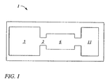
- FIG.1 shows a general block diagram of a mass spectrometry system I of the present invention.
- the block diagram is not to scale and is drawn in a general format because the present invention may be used with a variety of different types of mass spectrometry systems.
- the mass spectrometry system 1 of the present invention comprises an ion source 3, an ion enhancement system 2, an ion transport system 6 and a detector 11.
- the ion enhancement system 2 may be interposed between the ion source 3 and the ion detector 11 or may comprise part of the ion source 3 and/or part of the ion transport system 6.
- the ion source 3 may be located in any number of positions or locations.
- a variety of ion sources may be used with the present invention.
- El, CI, MALDI, AP-MALDI, photo ionization or other ion sources well known in the art may be used with the invention.
- Other sources known in the art may be employed that provide for ions or spraying of ions.
- the ion source 3 may comprise an ionization device 8 that will be used to produce ions used or employed by the present invention.
- the ionization device 8 may comprise any number of devices in any number of designs and locations.
- the ion enhancement system 2 may comprise a first gas source 7. Further details of the ion enhancement system 2 are provided below.
- the ion enhancement system 2 should not be interpreted to be limited to just these configurations or embodiments. Other designs and arrangements are possible and the limited embodiments provided here are for illustration purposes only and should not be interpreted as to limit the broad scope of the invention.
- the ion transport system 6 is adjacent to the ion enhancement system 2 and may comprise a collection conduit 9 or any ion optics, conduits or devices that may transport analyte ions and that are well known in the art.
- Other device may include the use of ion guides, multipole ion guides, or other similar type devices that are well known in the art.
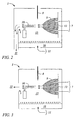
- FIG. 2 shows a first embodiment of the present invention.
- the figure is not to scale and is used for illustrative purposes.
- the ion source 3 comprises the ionization device 8 in the form of a nebulizer 17.
- An optional counter electrode 20 may be employed with the present invention.
- the counter electrode 20 is often employed to direct ions toward the collection conduit 9. In certain instances and embodiments the counter electrode 20 may comprise a steering electrode.
- the ionization device 8 may be oriented in any number of arrangements or locations relative to the collection conduit 9.
- the ionization device 8 is designed to provide ions or spray them into the ionization region 15.
- the ionization device 8 may be in the form of any device known in the art for producing or spraying ions.
- the nebulizer 17 may comprise any number of nebulizers known in the art.
- the nebulizer 17 may be placed in any number of locations or orientations to maximize the output to the ionization region 15.
- the collection conduit 9 is located downstream from the ion source 3 and may comprise a variety of materials and designs that are well known in the art.
- the collection conduit 9 is designed to receive and collect analyte ions produced from the ionization device 8 that are discharged into the ionization region 15.
- the collection conduit 9 has an aperture and/or elongated bore 12 that receives the analyte ions and transports them to another conduit or location.
- the collection conduit 9 may comprise a variety of materials and devices well known in the art.
- the collection conduit 9 may comprise a sleeve, transport device, dispenser, nozzle, hose, pipe, pipette, port, connector, tube, coupling, container, housing structure or apparatus that is used to direct a heated gas or gas flow toward a defined region in space or location such as the ionization region 15. It is important to the invention that the col lection conduit 9 be positioned sufficiently close to the ionization region 15 so that a sufficient amount of heated gas can be applied to the ions in the ionization region 15. The heated gas is provided to the ionization region 15 by way of the first gas source 7.
- the first gas source 7 is used to provide a heated gas to the ionization region 15.
- the heated gas provides a way to "enhance" the analyte ion being sprayed or ejected into the ionization region 15.
- the heat provided to the gas may be regulated in a number of different ways. For instance, the gas may be pre-heated and circulated or may be circulated and then later heated before it enters the ionization region 15.
- the first gas source 7 may comprise any number of devices to provide heated gas. Gas sources are well known in the art and are described elsewhere.
- the first gas source 7 may be a separate component or may be integrated with a coupling or other device that operatively joins the first gas source 7 to another device.
- the first gas source 7 may provide a number of gases that are to be collected by collection conduit 9.
- gases such as nitrogen, argon, xenon, carbon dioxide, air, helium etc..
- the gas need not be inert and should be capable of carrying a sufficient quantum of energy or heat.
- gases well known in the art that contain these characteristic properties may also be used with the present invention.
- the flow of gas from the first gas source through the ionization region may be collected by an exit port such that the first gas preferentially exits through this port, thereby reducing recirculation of the gas which will have ions present that were not collected by the collection conduit.
- the second gas source 11 is important to the invention.
- the second gas source 11 may be located in any number of locations or arrangements within the ion source 3. However, the second gas source 11 provides a gas at a defined and regulated rate to the ionization region 15. The defined and regulated rate of gas flow across the ion source provides for improvement in sensitivity and ion stability during capture by the collection conduit 9.
- the second gas source 11 may comprise any number of devices to provide gas. Gas sources may comprise conduits, housing, plates, plates with apertures, walls in the chamber, a reservoir or any other similar type device that can provide for a defined and consistent flow rate across the ion source 3.
- the second gas source 11 may be a separate component or may be integrated with a coupling or other device that operatively joins the second gas source 11 to another device.
- the second gas source 7 may provide a number of different types of gases to the ion source 3 and/or ionization region 15.
- the gas provided may be the same or different from the first gas source 7.
- gases such as nitrogen, argon, xenon, carbon dioxide, air, helium etc.. may be used with the present invention.
- the gas need not be inert and may be capable of carrying a sufficient quantum of energy or heat.
- Other gases well known in the art that contain these characteristic properties may also be used with the present invention.
- the gas supplied by the second gas source 11 be in a regulated and continuous fashion. In other words, the gas is provided in a continuous and controlled fashion across the chamber of the ion source 3.
- the structure of the second gas source 11 be capable of providing a continuous and continuously distributed gas to the chamber of the ion source 3.
- the exit of the second source gas is configured such that recirculation of the second gas is minimized.
- the ionization region 15 comprises the space and area located in the area between the ion source 3 and the collection conduit 9. This region contains the ions produced by ionizing the samples that are vaporized into a gas phase. This region can be adjusted in size and shape depending upon how the ion source 3 is arranged relative to the collection conduit 9. Most importantly, located in this region are the analyte ions produced by the ionization device 8.
- FIG. 2 also shows the first gas source 7 and the second gas source 11.
- the first gas source 7 provides a flow of heated gas toward the ions in the ionization region 15.
- the heated gas interacts with the analyte ions in the ionization region 15 to enhance the analyte ions and allow them to be more easily detected by the detector 11 (not shown in FIG. 2).
- These ions include the ions that exist in the heated gas phase.
- the detector 11 is located further downstream in the mass spectrometry system (see FIG. 1).
- an ionization device 8 of the invention may comprise an axis of ion movement defined by the longitudinal axis of the ion collection conduit 9, i.e., the ion collection conduit 9 comprises a longitudinal axis that the ions move along.
- the axis of heated gas flow is defined by the longitudinal axis of the conduit that provides the heated gas, i.e., a molecular axis that the heated gas moves along.
- the axis of gas flow from the first gas source 7 may be at any angle from 0° and 360 °, including the angles of 0° and 360°, relative to the axis of ion movement from the ionization device 8 to the entrance of the ion collection conduit.
- the axis of gas flow may be opposing or anti-parallel (i.e. about 180 degrees), parallel (i.e., about 0 degrees) or orthogonal to the axis of ion flow, or any angle there between.
- the direction of flow of the heated gas is at any angle in the following ranges: of 0-30 degrees, 30-60 degrees, 50-90 degrees, 90-120 degrees, 120-150 degrees, 150-180 degrees, 180-210 degrees, 210-240 degrees, 240-270 degrees, 270-300 degrees, 300-330 degrees, 330-360 degrees with respect to the axis of ion flow.
- the axis headed gas is oriented orthogonally to the axis of ion movement.
- the angles listed above may be any angle in two or three dimensional space.
- the angle may be in an x/y plane (i.e., in the same plane as Fig. 3), or in a z plane (i.e., the axis of heated gas may be oriented above or below the x/y plane of Fig. 3) or a combination thereof.
- the axis of heated gas may be at any angle relative to the axis of ion transport.
- the detector 11 is located downstream from the ion source 3 and the collection conduit 9.
- the detector 11 may be a mass analyzer or other similar device well known in the art for detecting the enhanced analyte ions that were collected by the collection conduit 9.
- the detector 11 may also comprise any computer hardware and software that are well known in the art and which may help in detecting enhanced analyte ions.
- the ionization device 8 provides an initial source of ions to the ionization region 15. These charged droplets are generally in a format that comprises analyte and solvent. Once sprayed or directed into the ionization region 15, the charged droplets can then be desolvated to concentrate them before they enter the collection conduit 9. This may be accomplished by using a first gas source 7 to direct a heated gas into the ionization region 15 to contact and dry the molecules. In addition, the second gas source 11 provides a second gas to the ion source 3 at a steady and defined rate.
- the gas can be directed through a variety of apertures that connect with an outside area 16 of the ion source 3 to the ionization region 15.
- the first gas source 9 heats the analyte and helps to desolvate it, the ions that are not collected by the collection conduit 9 continue to pass though the chamber[RB7] and then out the exhaust port 22.
- the exhaust port 22 is not present or in an effective location to remove contaminants or unwanted materials.
- the exhaust port 22 is placed such that the gas from the first gas source 7 is preferentially and, ideally, completely collected and exhausted from the chamber.
- An alternate embodiment, shown in FIG 3, places the exhaust port 22 such that the gas from the first gas source[RB9].
- the exhaust port may be configured in a few different arrangements.
- the first is a separate exhaust that is meant primarily for only the second gas and the second method is an exhaust that serves to put out both the first and second gases at the same time while preventing recirculation of the ions in the chamber.
- the first method can be accomplished by using a plate similar to that used at the second gas source.
- the second method can be accomplished by a similar version of the configuration shown in FIG 2.
Landscapes
- Physics & Mathematics (AREA)
- Engineering & Computer Science (AREA)
- Plasma & Fusion (AREA)
- Chemical & Material Sciences (AREA)
- Analytical Chemistry (AREA)
- Other Investigation Or Analysis Of Materials By Electrical Means (AREA)
- Electron Tubes For Measurement (AREA)
Abstract
The invention described herein provides a mass spectrometry system, having an ion source including an ionization device for producing ions, a collection conduit adjacent to the ionization device for collecting ions produced by the ionization device, a first gas source for supplying gas to desolvate ions produced by the ionization device, a second gas source for supplying gas at a defined flow to the ionization region, and a detector downstream from the ion source for detecting ions produced by the ion source. The invention also provides an ion source including an ionization device for producing ions, a collection conduit adjacent to the ionization device for collecting ions produced by the ionization device, a first gas source for supplying gas to desolvate ions produced by the ionization device, and a second gas source for supplying gas at a defined flow to the ionization region.
A method for producing analyte ions is also disclosed. The method includes producing analyte ions from an ionization device, directing a first heated gas toward the analyte ions to desolvate the analyte ions, and directing a second gas toward the analyte ions at a defined and continual flow rate.
Description
- Mass spectrometers work by ionizing molecules and then sorting and identifying the molecules based on their mass-to-charge (m/z) ratios. Several different types of ion sources are available for mass spectrometry systems. Each different ion source has particular advantages and disadvantages for different types of molecules to be analyzed.
- Much of the advancement in liquid chromatography (LC/MS) over the last ten years has been in the development of ion sources. The introduction of techniques that are performed at atmospheric pressure have been of particular interest. These techniques do not require the use of complex pumps and pumping techniques to create a vacuum. Common techniques include and are not limited to electrospray ionization (ESI), atmospheric pressure chemical ionization (APCI), and atmospheric pressure photoionization (APPI). Other more recent techniques include matrix assisted laser desorption ionization (MALDI) and atmospheric matrix assisted laser desorption ionization (AP-MALDI).
- ESI is the oldest and most studied of the above-mentioned techniques. Electrospray ionization works by a technique that relies in part on chemistry of the molecules to generate analyte ions in solution before the analyte reaches the mass spectrometer. The liquid eluent is sprayed into a chamber at atmospheric pressure. The analyte ions are then spatially and electrostatically separated from neutral molecules. More recently; there has been a trend toward developing ESI ion sources that provide increased sensitivity, mass accuracy and signal stability.
- Currently, the drying gas used in an ambient pressure ESI spray chamber is used for desolvating electrospray droplets. The drying gas then typically re-circulates in the chamber until it either exits the chamber via an opening or an exhaust port. Present systems suffer from the limitation of recirculation into the chamber, contamination by circulating species or sample residue. In particular, these contaminants can also impact signal strength which effects the quality of the final spectra obtained. For instance, signal strength can be reduced through poor ionization, poor efficiency in gathering the ions in the mass spectrometer and many other ways. In addition, a significant problem concerns the ability to maintain overall signal stabilities. Current methods and instrument designs provide a drying gas that enters the ionization chamber with a high velocity. The high gas velocity in many cases is needed to obtain the desired level of drying. However, this also negatively impacts spectra, spectra stability and overall instrument sensitivity. These and other problems have been overcome by the present invention.
- The present invention relates to an apparatus and method for use with a mass spectrometry system. The invention provides a mass spectromery system, comprising an ion source comprising an ionization device for producing ions, a collection conduit adjacent to the ionization device for collecting ions produced by the ionization device, a first gas source for supplying gas to desolvate ions produced by the ionization device and a second gas source disposed in the ion source for supplying a second gas at a defined, regulated flow rate to the ionization region; and a detector downstream from the ion source for detecting ions produced by the ion source.
- The invention also provides an ion source comprising an ionization device for producing ions, a collection conduit adjacent to the ionization device for collecting ions produced by the ionization device, a first gas source for supplying gas to desolvate ions produced by the ionization device and a second gas source disposed in the ion source for supplying a second gas at a defined, regulated flow rate to the ionization region.
- The method of the present invention comprises producing analyte ions from an ionization device, directing a first heated gas toward the analyte ions to desolvate the analyte ions, and directing a second gas toward the analyte ions at a defined and continual flow rate to improve the signal to noise ratio of the mass spectrometry system.
- The invention is described in detail below with reference to the following figures:
- FIG. 1 shows general block diagram of a mass spectrometer.
- FIG 2 shows a first embodiment of the present invention.
- FIG. 3 shows a second embodiment of the present invention.
- Before describing the invention in detail, it must be noted that, as used in this specification and the appended claims, the singular forms "a," "an," and "the" include plural referents unless the context clearly dictates otherwise. Thus, for example, reference to "a conduit" includes more than one "conduit". Reference to a "matrix" includes more than one "matrix" or a mixture of "matrixes". In describing and claiming the present invention, the following terminology will be used in accordance with the definitions set out below.
- The term "adjacent" means, near, next to or adjoining. Something adjacent may also be in contact with another component, surround the other component, be spaced from the other component or contain a portion of the other component. For instance, a capillary that is adjacent to a conduit may be spaced next to the conduit, may contact the conduit, may surround or be surrounded by the conduit, may contain the conduit or be contained by the conduit, may adjoin the conduit or may be near the conduit.
- The term "conduit" or "collection conduit" refers to any sleeve, transport device, dispenser, nozzle, hose, pipe, plate, pipette, port connector, tube, coupling, container, housing, structure or apparatus that may be used to receive a gas. In particular, a "collection conduit" may be designed to enclose a capillary or portion of a capillary that receives analyte ions from an ion source. The term should be interpreted broadly, however, to also include any device, or apparatus that may be oriented toward the ionization region and which can receive ions.
- The term "first gas source" refers to any source, structure, design, conduit, or apparatus that provides a gas to an ionization region.
- The term "second gas source" refers to any source, structure, design, conduit, or apparatus that provides gas at a defined and regulated flow rate to an ionization region.
- The term "enhance" refers to any external physical stimulus such as heat, energy, light, or temperature change, etc.. that makes a sub stance more easily characterized or identified. For example, a heated gas may be applied by a first gas source to "enhance" ions. The ions increase their kinetic energy, potentials or motions and are declustered or vaporized. Ions in this state are more easily detected by a mass analyzer. It should be noted that when the ions are "enhanced", the number of ions detected is enhanced since a higher number of analyte ions are sampled through a collection conduit and carried to a mass analyzer or detector.
- The term "ion source" or "source" refers to any source that produces analyte ions. Ion sources may include other sources besides AP-MALDI ion sources such as electron impact (herein after referred to as EI), chemical ionization (CI) and other ion sources known in the art. An ion source described herein may have an ambient pressure (i.e., a temperature within the housing of the ion source) of below 100 mTorr or at least 100 mTorr. In certain embodiments an ion source may have an ambient pressure that is atmospheric pressure (approximately 760 Torr), or high vacuum pressure, for example.
- The term "ionization device" refers to any device, apparatus, nebulizer or conduit that may be employed to produce ions. The ions produced may typically comprise an analyte in a solvent.
- The term "ionization region" refers to the area between the ionization device and the collection conduit. In particular, the term refers to the analyte ions produced by the ion source that reside in that region and which have not yet been channeled into the collection conduit.
- The terms "matrix based", or "matrix based ion source" refers to an ion source or mass spectrometry system that does not require the use of a drying gas, curtain gas, or a desolvation step. For instance, some systems require the use of such gases to remove solvent or cosolvent that is mixed with the analyte. These systems often use volatile liquids to help form smaller droplets. The above term applies to both nonvolatile liquids and solid materials in which the sample is dissolved. The term includes the use of a cosolvent. Cosolvents may be volatile or nonvolatile, but must not render the final matrix material capable of evaporating in vacuum. Such materials would include, and not be limited to m-nitrobenzyl alcohol (MBA), glycerol, triethanolamine (TEA), 2,4-dipentylphenol,1,5-dithiothrietol/dierythritol (magic bullet), 2-nitrophenyl octyl ether (NPOE), thioglycerol, nicotinic acid, cinnamic acid, 2,5-dihydroxy benzoic acid (DHB), 3,5-dimethoxy-4-hydroxycinnamic acid (sinpinic acid), a-cyano-4-hydroxycinnamic acid (CCA), 3-methoxy-4-hydroxycinnamic acid (ferulic acid), monothioglycerol, carbowax, 2-(4-hydroxyphenylazo)benzoic acid (HABA), 3,4-dihydroxycinnamic acid (caffeic acid), 2-amino-4-methyl-5-nitropvridine with their cosolvents and derivatives. In particular the term refers to MALDI, AP-MALDI, fast atom/ion bombardment (FAB) and other similar systems that do not require a volatile solvent and may be operated above, at, and below atmospheric pressure.
- The term "gas flow", "gas", or "directed gas" refers to any gas that is directed in a defined direction in a mass spectrometry system. The term should be construed broadly to include monatomic, diatomic, triatomic and polyatomic molecules that can be passed or be blown through a conduit. The term should also be construed broadly to include mixtures, impure mixtures, or contaminants. The term includes both inert and non-inert matter. Common gases used with the present invention could include and not be limited to ammonia, carbon dioxide, helium, fuorine, argon, xenon, nitrogen, air etc..
- The term "gas source" refers to any apparatus, machine, conduit, or device that produces a desired gas or gas flow. Gas sources often produce regulated gas flow, but this is not required.
- The term "detector" refers to any device, apparatus, machine, component, or system that can detect an ion. Detectors may or may not include hardware and software. In a mass spectrometry system the common detector includes and/or is coupled to a mass analyzer.
- A "plurality" is at least 2, e.g., 2, 3, 4, 6, 8, 10, 12 or greater than 12. The phrases "a plurality of' and "multiple" are used interchangeably.
- The invention is described with reference to the figures. The figures are not to scale, and in particular, certain dimensions may be exaggerated for clarity of presentation.
- FIG.1 shows a general block diagram of a mass spectrometry system I of the present invention. The block diagram is not to scale and is drawn in a general format because the present invention may be used with a variety of different types of mass spectrometry systems. The mass spectrometry system 1 of the present invention comprises an
ion source 3, anion enhancement system 2, anion transport system 6 and adetector 11. Theion enhancement system 2 may be interposed between theion source 3 and theion detector 11 or may comprise part of theion source 3 and/or part of theion transport system 6. - The
ion source 3 may be located in any number of positions or locations. In addition, a variety of ion sources may be used with the present invention. For instance, El, CI, MALDI, AP-MALDI, photo ionization or other ion sources well known in the art may be used with the invention. Other sources known in the art may be employed that provide for ions or spraying of ions. Typically, theion source 3 may comprise anionization device 8 that will be used to produce ions used or employed by the present invention. Theionization device 8 may comprise any number of devices in any number of designs and locations. - The
ion enhancement system 2 may comprise afirst gas source 7. Further details of theion enhancement system 2 are provided below. Theion enhancement system 2 should not be interpreted to be limited to just these configurations or embodiments. Other designs and arrangements are possible and the limited embodiments provided here are for illustration purposes only and should not be interpreted as to limit the broad scope of the invention. - The
ion transport system 6 is adjacent to theion enhancement system 2 and may comprise acollection conduit 9 or any ion optics, conduits or devices that may transport analyte ions and that are well known in the art. Other device may include the use of ion guides, multipole ion guides, or other similar type devices that are well known in the art. - FIG. 2 shows a first embodiment of the present invention. The figure is not to scale and is used for illustrative purposes. The
ion source 3 comprises theionization device 8 in the form of a nebulizer 17. Anoptional counter electrode 20 may be employed with the present invention. Thecounter electrode 20 is often employed to direct ions toward thecollection conduit 9. In certain instances and embodiments thecounter electrode 20 may comprise a steering electrode. Theionization device 8 may be oriented in any number of arrangements or locations relative to thecollection conduit 9. Theionization device 8 is designed to provide ions or spray them into theionization region 15. - The
ionization device 8 may be in the form of any device known in the art for producing or spraying ions. The nebulizer 17 may comprise any number of nebulizers known in the art. The nebulizer 17 may be placed in any number of locations or orientations to maximize the output to theionization region 15. - The
collection conduit 9 is located downstream from theion source 3 and may comprise a variety of materials and designs that are well known in the art. Thecollection conduit 9 is designed to receive and collect analyte ions produced from theionization device 8 that are discharged into theionization region 15. Thecollection conduit 9 has an aperture and/or elongated bore 12 that receives the analyte ions and transports them to another conduit or location. Thecollection conduit 9 may comprise a variety of materials and devices well known in the art. For instance, thecollection conduit 9 may comprise a sleeve, transport device, dispenser, nozzle, hose, pipe, pipette, port, connector, tube, coupling, container, housing structure or apparatus that is used to direct a heated gas or gas flow toward a defined region in space or location such as theionization region 15. It is important to the invention that thecol lection conduit 9 be positioned sufficiently close to theionization region 15 so that a sufficient amount of heated gas can be applied to the ions in theionization region 15. The heated gas is provided to theionization region 15 by way of thefirst gas source 7. - The
first gas source 7 is used to provide a heated gas to theionization region 15. The heated gas provides a way to "enhance" the analyte ion being sprayed or ejected into theionization region 15. The heat provided to the gas may be regulated in a number of different ways. For instance, the gas may be pre-heated and circulated or may be circulated and then later heated before it enters theionization region 15. Thefirst gas source 7 may comprise any number of devices to provide heated gas. Gas sources are well known in the art and are described elsewhere. Thefirst gas source 7 may be a separate component or may be integrated with a coupling or other device that operatively joins thefirst gas source 7 to another device. Thefirst gas source 7 may provide a number of gases that are to be collected bycollection conduit 9. For instance, gases such as nitrogen, argon, xenon, carbon dioxide, air, helium etc.. may be used with the present invention. The gas need not be inert and should be capable of carrying a sufficient quantum of energy or heat. Other gases well known in the art that contain these characteristic properties may also be used with the present invention. The flow of gas from the first gas source through the ionization region may be collected by an exit port such that the first gas preferentially exits through this port, thereby reducing recirculation of the gas which will have ions present that were not collected by the collection conduit. Important to the invention is thesecond gas source 11. Thesecond gas source 11 may be located in any number of locations or arrangements within theion source 3. However, thesecond gas source 11 provides a gas at a defined and regulated rate to theionization region 15. The defined and regulated rate of gas flow across the ion source provides for improvement in sensitivity and ion stability during capture by thecollection conduit 9. Thesecond gas source 11 may comprise any number of devices to provide gas. Gas sources may comprise conduits, housing, plates, plates with apertures, walls in the chamber, a reservoir or any other similar type device that can provide for a defined and consistent flow rate across theion source 3. Thesecond gas source 11 may be a separate component or may be integrated with a coupling or other device that operatively joins thesecond gas source 11 to another device. Thesecond gas source 7 may provide a number of different types of gases to theion source 3 and/orionization region 15. The gas provided may be the same or different from thefirst gas source 7. For instance, gases such as nitrogen, argon, xenon, carbon dioxide, air, helium etc.. may be used with the present invention. The gas need not be inert and may be capable of carrying a sufficient quantum of energy or heat. Other gases well known in the art that contain these characteristic properties may also be used with the present invention. It is important to the invention that the gas supplied by thesecond gas source 11 be in a regulated and continuous fashion. In other words, the gas is provided in a continuous and controlled fashion across the chamber of theion source 3. It is important to the invention that the structure of thesecond gas source 11 be capable of providing a continuous and continuously distributed gas to the chamber of theion source 3. The exit of the second source gas is configured such that recirculation of the second gas is minimized. - The
ionization region 15 comprises the space and area located in the area between theion source 3 and thecollection conduit 9. This region contains the ions produced by ionizing the samples that are vaporized into a gas phase. This region can be adjusted in size and shape depending upon how theion source 3 is arranged relative to thecollection conduit 9. Most importantly, located in this region are the analyte ions produced by theionization device 8. - FIG. 2 also shows the
first gas source 7 and thesecond gas source 11. Thefirst gas source 7 provides a flow of heated gas toward the ions in theionization region 15. The heated gas interacts with the analyte ions in theionization region 15 to enhance the analyte ions and allow them to be more easily detected by the detector 11 (not shown in FIG. 2). These ions include the ions that exist in the heated gas phase. Thedetector 11 is located further downstream in the mass spectrometry system (see FIG. 1). - Molecules generally move from the nebulizer 17 to the entrance of the
ion collection conduit 9. Accordingly, for the purposes of this disclosure, anionization device 8 of the invention may comprise an axis of ion movement defined by the longitudinal axis of theion collection conduit 9, i.e., theion collection conduit 9 comprises a longitudinal axis that the ions move along. Further, for the purposes of this disclosure, the axis of heated gas flow is defined by the longitudinal axis of the conduit that provides the heated gas, i.e., a molecular axis that the heated gas moves along. - In certain embodiments and as illustrated in Figs. 2 and 3, the axis of gas flow from the
first gas source 7 may be at any angle from 0° and 360 °, including the angles of 0° and 360°, relative to the axis of ion movement from theionization device 8 to the entrance of the ion collection conduit. For example, the axis of gas flow may be opposing or anti-parallel (i.e. about 180 degrees), parallel (i.e., about 0 degrees) or orthogonal to the axis of ion flow, or any angle there between. - In certain embodiments, the direction of flow of the heated gas is at any angle in the following ranges: of 0-30 degrees, 30-60 degrees, 50-90 degrees, 90-120 degrees, 120-150 degrees, 150-180 degrees, 180-210 degrees, 210-240 degrees, 240-270 degrees, 270-300 degrees, 300-330 degrees, 330-360 degrees with respect to the axis of ion flow. In particular embodiments, the axis headed gas is oriented orthogonally to the axis of ion movement.
- The angles listed above may be any angle in two or three dimensional space. In other words, the angle may be in an x/y plane (i.e., in the same plane as Fig. 3), or in a z plane (i.e., the axis of heated gas may be oriented above or below the x/y plane of Fig. 3) or a combination thereof. In other words, viewed from the side (as shown in Fig. 3) or from "above" (e.g., from the entrance of the ion collection capillary) the axis of heated gas may be at any angle relative to the axis of ion transport.
- Referring now to FIGS. 1-3, the
detector 11 is located downstream from theion source 3 and thecollection conduit 9. Thedetector 11 may be a mass analyzer or other similar device well known in the art for detecting the enhanced analyte ions that were collected by thecollection conduit 9. Thedetector 11 may also comprise any computer hardware and software that are well known in the art and which may help in detecting enhanced analyte ions. - Having described the apparatus of the present invention, a description of the method of the invention is now in order.
- Referring now to FIGS. 1-3 the method of the present invention can now be described. The
ionization device 8 provides an initial source of ions to theionization region 15. These charged droplets are generally in a format that comprises analyte and solvent. Once sprayed or directed into theionization region 15, the charged droplets can then be desolvated to concentrate them before they enter thecollection conduit 9. This may be accomplished by using afirst gas source 7 to direct a heated gas into theionization region 15 to contact and dry the molecules. In addition, thesecond gas source 11 provides a second gas to theion source 3 at a steady and defined rate. As shown in the figure, the gas can be directed through a variety of apertures that connect with anoutside area 16 of theion source 3 to theionization region 15. Once thefirst gas source 9 heats the analyte and helps to desolvate it, the ions that are not collected by thecollection conduit 9 continue to pass though the chamber[RB7] and then out theexhaust port 22. In many current designs theexhaust port 22 is not present or in an effective location to remove contaminants or unwanted materials. As shown in FIG 2, theexhaust port 22 is placed such that the gas from thefirst gas source 7 is preferentially and, ideally, completely collected and exhausted from the chamber. An alternate embodiment, shown in FIG 3, places theexhaust port 22 such that the gas from the first gas source[RB9]. - The exhaust port may be configured in a few different arrangements. The first is a separate exhaust that is meant primarily for only the second gas and the second method is an exhaust that serves to put out both the first and second gases at the same time while preventing recirculation of the ions in the chamber. The first method can be accomplished by using a plate similar to that used at the second gas source. The second method can be accomplished by a similar version of the configuration shown in FIG 2.
- It is to be understood that while the invention has been described in conjunction with the specific embodiments thereof, that the foregoing description as well as the examples that follow are intended to illustrate and not limit the scope of the invention. Other aspects, advantages and modifications within the scope of the invention will be apparent to those skilled in the art to which the invention pertains.
- All patents, patent applications, and publications infra and supra mentioned herein are hereby incorporated by reference in their entireties.
Claims (27)
- An ion source comprising:(a) an ionization device for producing ions and delivering them to an ionization region;(b) a collection conduit adjacent to the ionization device for collecting ions produced by the ionization device;(c) a first gas source for supplying gas to desolvate ions produced by the ionization device; and(d) a second gas source for supplying gas at a defined flow to the ionization region.
- An ion source as recited in claim 1, wherein the ionization device comprises an electrospray device.
- An ion source as recited in claim 1, wherein the ionization device comprises a MALDI device.
- An ion source as recited in claim 1, wherein the ionization device comprises an AP-MALDI device.
- An ion source as recited in claim 1, wherein the second gas source comprises a plate.
- An ion source as recited in claim 5, wherein the place comprises at least one aperture for delivering gas to the ionization region.
- An ion source as recited in claim 1, wherein the second gas source comprises a conduit.
- An ion source as recited in claim 1, wherein the second gas source comprises a plurality of conduits.
- An ion source as recited in claim 1, wherein the second gas source comprises a reservoir having an aperture for delivering a gas.
- An ion source as recited in claim 1, wherein the first gas source delivers gas in molecular longitudinal axis that is parallel to the collection conduit.
- An ion source as recited in claim 1, where the second gas source delivers gas in a molecular longitudinal axis that is transverse to the molecular longitudinal axis of the gas delivered by the first gas source.
- An ion source as recited in claim 1, wherein the second gas source comprises a reservoir having a plurality of apertures for delivering a gas.
- An ion source as recited in claim 1, that further comprises an exhaust port for removing the gas produced from the second gas source
- An ion source as recited in claim 1, further comprising an exhaust port for removing the gas produced by the first gas source and the second gas source.
- A mass spectrometry system, comprising:(a) an ion source comprising:(i) an ionization device for producing ions and delivering them to an ionization region;(ii) a collection conduit adjacent to the ionization device for collecting ions produced by the ionization device;(iii) a first gas source for supplying gas to desolvate ions produced by the ionization device; and(iv) a second gas source for supplying gas at a defined flow rate to the ionization region; and(b) a detector downstream from the ion source for detecting ions produced by the ion source.
- A mass spectrometry system as recited in claim 15, wherein the ionization device comprises an electrospray device.
- A mass spectrometry system as recited in claim 15, wherein the ionization device comprises a MALDI device.
- A mass spectrometry system as recited in claim 15, wherein the ionization device comprises an AP-MALDI device.
- A mass spectrometry system as recited in claim 15, wherein the second gas source comprises a plate.
- A mass spectrometry system as recited in claim 19, wherein the plate comprises at least one aperture.
- A mass spectrometry system as recited in claim 15, wherein the second gas source comprises a conduit.
- A mass spectrometry system as recited in claim 15, wherein the second gas source comprises a plurality of conduits.
- A mass spectrometry system as recited in claim 15, wherein the second gas source comprises a reservoir having an aperture for delivering a gas.
- A mass spectrometry system as recited in claim 15, wherein the second gas source comprises a reservoir having a plurality of apertures for delivering a gas.
- A mass spectrometry system as recited in claim 15, wherein the first gas source delivers gas in a stream with a molecular longitudinal axis that is parallel to the collecting conduit.
- A mass spectrometry system as recited in claim 15, where the second gas source delivers gas in a stream with a molecular longitudinal axis that is transverse to the molecular longitudinal axis of the stream of gas delivered by the first gas source.
- The method of improving a mass spectrometers sensitivity, comprises:(a) producing analyte ions from an ionization device,(b) directing a first heated gas toward the analyte ions to desolvate the analyte ions; and(c) directing a second gas toward the analyte ions at a defined and continual flow rate to improve the mass spectrometers sensitivity.
Applications Claiming Priority (1)
| Application Number | Priority Date | Filing Date | Title |
|---|---|---|---|
| US11/216,884 US7397028B2 (en) | 2005-08-30 | 2005-08-30 | Apparatus and method for gas flow management |
Publications (1)
| Publication Number | Publication Date |
|---|---|
| EP1760765A2 true EP1760765A2 (en) | 2007-03-07 |
Family
ID=37546843
Family Applications (1)
| Application Number | Title | Priority Date | Filing Date |
|---|---|---|---|
| EP06000653A Withdrawn EP1760765A2 (en) | 2005-08-30 | 2006-01-12 | Apparatus and method for gas flow management |
Country Status (3)
| Country | Link |
|---|---|
| US (1) | US7397028B2 (en) |
| EP (1) | EP1760765A2 (en) |
| JP (1) | JP2007066903A (en) |
Cited By (1)
| Publication number | Priority date | Publication date | Assignee | Title |
|---|---|---|---|---|
| US12578307B2 (en) | 2020-04-03 | 2026-03-17 | Micromass Uk Limited | De-clustering ion guide |
Families Citing this family (5)
| Publication number | Priority date | Publication date | Assignee | Title |
|---|---|---|---|---|
| US7385189B2 (en) * | 2005-06-29 | 2008-06-10 | Agilent Technologies, Inc. | Nanospray ionization device and method |
| US8502162B2 (en) * | 2011-06-20 | 2013-08-06 | Agilent Technologies, Inc. | Atmospheric pressure ionization apparatus and method |
| WO2014171378A1 (en) * | 2013-04-19 | 2014-10-23 | 株式会社島津製作所 | Mass spectroscopy device |
| JP7032286B2 (en) * | 2018-11-08 | 2022-03-08 | 株式会社日立ハイテク | Ion source |
| EP3998624A4 (en) | 2019-07-10 | 2023-03-29 | Hitachi High-Tech Corporation | MASS SPECTROMETER |
Family Cites Families (8)
| Publication number | Priority date | Publication date | Assignee | Title |
|---|---|---|---|---|
| US6690004B2 (en) * | 1999-07-21 | 2004-02-10 | The Charles Stark Draper Laboratory, Inc. | Method and apparatus for electrospray-augmented high field asymmetric ion mobility spectrometry |
| US6586732B2 (en) * | 2001-02-20 | 2003-07-01 | Brigham Young University | Atmospheric pressure ionization ion mobility spectrometry |
| US6683300B2 (en) * | 2001-09-17 | 2004-01-27 | Science & Engineering Services, Inc. | Method and apparatus for mass spectrometry analysis of common analyte solutions |
| US7005633B2 (en) * | 2002-02-08 | 2006-02-28 | Ionalytics Corporation | Method and apparatus for desolvating ions for introduction into a FAIMS analyzer region |
| US7026612B2 (en) * | 2002-02-08 | 2006-04-11 | Ionalytics Corporation | FAIMS apparatus and method using carrier gases that contain a trace amount of a dopant species |
| US6998608B2 (en) * | 2002-02-08 | 2006-02-14 | Ionalytics Corporation | FAIMS with non-destructive detection of selectively transmitted ions |
| US6649909B2 (en) * | 2002-02-20 | 2003-11-18 | Agilent Technologies, Inc. | Internal introduction of lock masses in mass spectrometer systems |
| US6825462B2 (en) | 2002-02-22 | 2004-11-30 | Agilent Technologies, Inc. | Apparatus and method for ion production enhancement |
-
2005
- 2005-08-30 US US11/216,884 patent/US7397028B2/en not_active Expired - Lifetime
-
2006
- 2006-01-12 EP EP06000653A patent/EP1760765A2/en not_active Withdrawn
- 2006-08-30 JP JP2006233023A patent/JP2007066903A/en active Pending
Cited By (1)
| Publication number | Priority date | Publication date | Assignee | Title |
|---|---|---|---|---|
| US12578307B2 (en) | 2020-04-03 | 2026-03-17 | Micromass Uk Limited | De-clustering ion guide |
Also Published As
| Publication number | Publication date |
|---|---|
| US7397028B2 (en) | 2008-07-08 |
| JP2007066903A (en) | 2007-03-15 |
| US20070045532A1 (en) | 2007-03-01 |
Similar Documents
| Publication | Publication Date | Title |
|---|---|---|
| US11133162B2 (en) | IRMS sample introduction system and method | |
| JP3993895B2 (en) | Mass spectrometer and ion transport analysis method | |
| US7002146B2 (en) | Ion sampling for APPI mass spectrometry | |
| US6649909B2 (en) | Internal introduction of lock masses in mass spectrometer systems | |
| US9754773B1 (en) | Internal solvent trap with drain | |
| US6825462B2 (en) | Apparatus and method for ion production enhancement | |
| US20130026359A1 (en) | Method and apparatus for generating and analyzing ions | |
| US20090045330A1 (en) | Sample ionization at above-vacuum pressures | |
| US6858841B2 (en) | Target support and method for ion production enhancement | |
| CN106373853B (en) | One kind is for mass spectrograph ionization and ion introducing device | |
| US20200041471A1 (en) | Ionizer and mass spectrometer | |
| US20070114437A1 (en) | MALDI/LDI source | |
| US7855357B2 (en) | Apparatus and method for ion calibrant introduction | |
| GB2410370A (en) | Desorption and ionization of analyte molecules from a sample support | |
| US20060131497A1 (en) | Atmospheric pressure ionization with optimized drying gas flow | |
| CN109716482B (en) | Method and system for controlling ion contamination | |
| US7135689B2 (en) | Apparatus and method for ion production enhancement | |
| US7372043B2 (en) | Apparatus and method for ion production enhancement | |
| US7397028B2 (en) | Apparatus and method for gas flow management | |
| US7132670B2 (en) | Apparatus and method for ion production enhancement | |
| US20070114386A1 (en) | Reference mass introduction via a capillary | |
| US20050151091A1 (en) | Apparatus and method for ion production enhancement |
Legal Events
| Date | Code | Title | Description |
|---|---|---|---|
| PUAI | Public reference made under article 153(3) epc to a published international application that has entered the european phase |
Free format text: ORIGINAL CODE: 0009012 |
|
| AK | Designated contracting states |
Kind code of ref document: A2 Designated state(s): AT BE BG CH CY CZ DE DK EE ES FI FR GB GR HU IE IS IT LI LT LU LV MC NL PL PT RO SE SI SK TR |
|
| AX | Request for extension of the european patent |
Extension state: AL BA HR MK YU |
|
| STAA | Information on the status of an ep patent application or granted ep patent |
Free format text: STATUS: THE APPLICATION HAS BEEN WITHDRAWN |
|
| 18W | Application withdrawn |
Effective date: 20091128 |