EP1760733B1 - Refrigerator with contactlessly powered movable member - Google Patents
Refrigerator with contactlessly powered movable member Download PDFInfo
- Publication number
- EP1760733B1 EP1760733B1 EP05108094A EP05108094A EP1760733B1 EP 1760733 B1 EP1760733 B1 EP 1760733B1 EP 05108094 A EP05108094 A EP 05108094A EP 05108094 A EP05108094 A EP 05108094A EP 1760733 B1 EP1760733 B1 EP 1760733B1
- Authority
- EP
- European Patent Office
- Prior art keywords
- refrigerator
- inductor
- compartment
- movable member
- circuit
- Prior art date
- Legal status (The legal status is an assumption and is not a legal conclusion. Google has not performed a legal analysis and makes no representation as to the accuracy of the status listed.)
- Active
Links
Images


Classifications
-
- H—ELECTRICITY
- H01—ELECTRIC ELEMENTS
- H01F—MAGNETS; INDUCTANCES; TRANSFORMERS; SELECTION OF MATERIALS FOR THEIR MAGNETIC PROPERTIES
- H01F38/00—Adaptations of transformers or inductances for specific applications or functions
- H01F38/14—Inductive couplings
-
- F—MECHANICAL ENGINEERING; LIGHTING; HEATING; WEAPONS; BLASTING
- F25—REFRIGERATION OR COOLING; COMBINED HEATING AND REFRIGERATION SYSTEMS; HEAT PUMP SYSTEMS; MANUFACTURE OR STORAGE OF ICE; LIQUEFACTION SOLIDIFICATION OF GASES
- F25D—REFRIGERATORS; COLD ROOMS; ICE-BOXES; COOLING OR FREEZING APPARATUS NOT OTHERWISE PROVIDED FOR
- F25D23/00—General constructional features
-
- F—MECHANICAL ENGINEERING; LIGHTING; HEATING; WEAPONS; BLASTING
- F25—REFRIGERATION OR COOLING; COMBINED HEATING AND REFRIGERATION SYSTEMS; HEAT PUMP SYSTEMS; MANUFACTURE OR STORAGE OF ICE; LIQUEFACTION SOLIDIFICATION OF GASES
- F25D—REFRIGERATORS; COLD ROOMS; ICE-BOXES; COOLING OR FREEZING APPARATUS NOT OTHERWISE PROVIDED FOR
- F25D25/00—Charging, supporting, and discharging the articles to be cooled
-
- F—MECHANICAL ENGINEERING; LIGHTING; HEATING; WEAPONS; BLASTING
- F21—LIGHTING
- F21V—FUNCTIONAL FEATURES OR DETAILS OF LIGHTING DEVICES OR SYSTEMS THEREOF; STRUCTURAL COMBINATIONS OF LIGHTING DEVICES WITH OTHER ARTICLES, NOT OTHERWISE PROVIDED FOR
- F21V23/00—Arrangement of electric circuit elements in or on lighting devices
- F21V23/02—Arrangement of electric circuit elements in or on lighting devices the elements being transformers, impedances or power supply units, e.g. a transformer with a rectifier
-
- F—MECHANICAL ENGINEERING; LIGHTING; HEATING; WEAPONS; BLASTING
- F21—LIGHTING
- F21Y—INDEXING SCHEME ASSOCIATED WITH SUBCLASSES F21K, F21L, F21S and F21V, RELATING TO THE FORM OR THE KIND OF THE LIGHT SOURCES OR OF THE COLOUR OF THE LIGHT EMITTED
- F21Y2115/00—Light-generating elements of semiconductor light sources
- F21Y2115/10—Light-emitting diodes [LED]
-
- F—MECHANICAL ENGINEERING; LIGHTING; HEATING; WEAPONS; BLASTING
- F25—REFRIGERATION OR COOLING; COMBINED HEATING AND REFRIGERATION SYSTEMS; HEAT PUMP SYSTEMS; MANUFACTURE OR STORAGE OF ICE; LIQUEFACTION SOLIDIFICATION OF GASES
- F25D—REFRIGERATORS; COLD ROOMS; ICE-BOXES; COOLING OR FREEZING APPARATUS NOT OTHERWISE PROVIDED FOR
- F25D2400/00—General features of, or devices for refrigerators, cold rooms, ice-boxes, or for cooling or freezing apparatus not covered by any other subclass
- F25D2400/40—Refrigerating devices characterised by electrical wiring
-
- F—MECHANICAL ENGINEERING; LIGHTING; HEATING; WEAPONS; BLASTING
- F25—REFRIGERATION OR COOLING; COMBINED HEATING AND REFRIGERATION SYSTEMS; HEAT PUMP SYSTEMS; MANUFACTURE OR STORAGE OF ICE; LIQUEFACTION SOLIDIFICATION OF GASES
- F25D—REFRIGERATORS; COLD ROOMS; ICE-BOXES; COOLING OR FREEZING APPARATUS NOT OTHERWISE PROVIDED FOR
- F25D27/00—Lighting arrangements
Definitions
- the present invention relates to a refrigerator having one or more movable members which are contactlessly powered for activating a power consuming device.
- refrigerator used herein means refrigerated cabinets in which the temperature is normally higher than 0 °C, and freezers in which the temperature is maintained below 0 °C, as well as combinations thereof.
- a refrigerator provided with electrically powered shelves according to the preamble of claim 1 is disclosed in the European Patent Application No. EP 1 503 159 .
- a refrigerator comprising a power bus disposed within the refrigerated compartment and electrically connected to a power source.
- a connector is disposed on the removable shelves. When the removable shelves are mounted within the compartment the connector is connected to the power bus to deliver power to the removable shelves.
- EP 1 503 159 does not overcome the above mentioned risk of electrical power dispersion within the refrigerated compartment which is a potential source of danger for the user.
- the reliability of the connector can be compromised after a number of connection/disconnection cycles as in the case of a refrigerated drawer powered as taught in the cited document.
- the aim of the present invention is therefore to solve the noted problems, eliminating the drawbacks of the cited known art and thus providing a refrigerator that avoids the risk of electrical power dispersion within the refrigerated compartments.
- a further object of the present invention is to provide a refrigerator in which electrical power can be delivered to any food supporting device associated to the refrigerator cabinet with an improved degree of safety.
- Another object of the present invention is to provide a refrigerator having means for delivering electrical power with improved reliability.
- Still another object of the invention is to provide a refrigerator easy to be assembled.
- Figure 1 shows a schematic perspective view of a first embodiment of a refrigerator according to the present invention
- Figure 2 shows a schematic perspective view of a possible arrangement for the first and second inductors in a refrigerator having movable members of different type
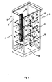
- Figure 3 shows a schematic perspective view of the refrigerator shown in Fig.1 having a first inductor extending vertically within a compartment and a second inductor coupled to it;
- Figure 4 shows a schematic perspective and enlarged view of the first and second inductors shown in Fig. 3 .
- a first embodiment of the refrigerator 1 comprises a cabinet 2 having outer walls 3 and inner walls 4 that define a compartment 5 for storing food to be refrigerated or frozen.
- the refrigerator door closing the compartment 5 has been removed to make the drawing clearer.
- Movable members 6, in the preferred form of shelves 19, are provided within the compartment 5 for dividing it in a plurality of portions.
- Each shelf 19 can be placed in a plurality of positions in a known manner for arranging the compartment 5 as desired.
- the cabinet 2 is provided with a primary electrical circuit 7 connected to a main alternate voltage power supply 8 which supplies an electrical power to first inductors 9.
- Each inductor 9 can comprise a first ferromagnetic element having a first electric coil 10 wrapped around it.
- Inductors 9 are preferably placed between an outer wall 3 and an inner wall 4 defining a portion of the compartment 5, in this way they are not visible neither from inside the compartment 5 nor from the outside of the cabinet 2.
- Each movable member 6 comprises a secondary electrical circuit 11 having a second inductor 12 which preferably comprises a second ferromagnetic element around which a second electrical coil 13 is wrapped.
- the secondary circuit 11 is contactlessly powered by the primary circuit 7 and such electrical power is supplied to a power consuming device 14 associated to the secondary circuit 11.
- the power consuming devices 14 are in the form of a light emitting unit such as a lamp or a LED, but it can equivalently be provided in the form of motor means or a fan.
- Motor means can be advantageously used, for example, in an ice-cream machine placed within the compartment 5.
- Fans can be provided to increase air turbulence within the compartment 5 for obtaining a uniform temperature distribution.
- the main alternate voltage power supply 8 comprises an oscillating circuit 15 able to supply the power needed at a pre-set frequency which is said resonating frequency.
- Power consuming devices 14 may be removably associated to a movable member 6 or it may be incorporated in the member 6 Itself.
- suitable connecting means will be provided on the members 6 and on the devices 14 for allowing electrical connection between the secondary circuit 11 and the device 14, while in the second case the device 14 can be incorporated in the member 6 together with the secondary circuit 11.
- FIG. 2 it is schematically shown a refrigerator 1 with a possible arrangement for the first and second inductors 9, 12 when the movable members 6 are in the form of shelves 19 and in the form of a drawer 20.
- the refrigerator door the power consumption devices 14 and the primary and secondary circuits 7, 11 have been omitted.
- the arrangement of the inductors 9, 12 In order to transfer electrical power form the refrigerator cabinet 2 to the movable shelves 19 has been already described with reference to Fig. 1 .
- the first inductor 9, having preferably a first ferromagnetic element carrying a first coil 10 is placed between an outer wall 3 of the cabinet 2 and an inner wall 4 defining a surface of a compartment 5.
- the second inductor 12 having a second ferromagnetic element carrying the second coil 13 is associated to the drawer 20 in a position facing the first inductor 9 when the drawer is completely inserted within the compartment 5. In this position electrical energy can be contactlessly transferred from the cabinet 2 to the drawer 20. Such power supply can be used to activate a fan (not shown) only when the drawer 20 is completely inside the compartment 5 thereby creating an air circulation in the drawer 20.
- shelves 19 can be contactlessly powered only when they are placed in particular pre-defined positions, that is in the positions corresponding to the displacement of the first inductors 9 which are fixed to the refrigerator 1. Since the user may desire to move the shelves continuously along the vertical direction of the compartment 5, a particular design for the first and second inductor has been provided. Such design is shown in Figs. 3 and 4 where primary and secondary circuits and are not shown.
- a refrigerator 1 is provided on its back, in a region between an outer wall 3 of the cabinet 2 and an inner wall 4 of the compartment 5, with a first inductor 9' that extends vertically within the compartment 5.
- the first inductor 9' is formed by an elongated-loop winding made of conductive material (e.g. enamelled copper) that generates a magnetic field having an elongated shape when powered.
- Shelves 19 are associated to a second inductor 12' having three spaced apart arms 21 protruding from a transversal bar 23 and preferably comprising a ferromagnetic element having an electric coil wrapped around it. Said arms 21 define two slots 22 adapted to receive a portion of the first inductor 12' such that electrical power can be contactlessly transferred from the primary circuit connected with the first inductor 9' to the secondary circuit associated to the second inductor 12'.
- each shelf 19 can be independently moved upward or downward as shown by the arrows "U” and “D". These movements can also be supplied by motor means, associated to the shelves 19, advantageously powered by the secondary circuit. Further power consuming devices 14, such as light emitting units, can be incorporated or removably associated to the shelves.
- a refrigerator 1 according to the present invention has an improved degree of safety because no connector is needed for powering a food supporting device associated to the refrigerator cabinet.
- the proposed solution is also advantageous because it simplifies the assembly of the refrigerator reducing the number of parts needed.
Abstract
Description
- The present invention relates to a refrigerator having one or more movable members which are contactlessly powered for activating a power consuming device.
- The term "refrigerator" used herein means refrigerated cabinets in which the temperature is normally higher than 0 °C, and freezers in which the temperature is maintained below 0 °C, as well as combinations thereof.
- It is known that in a refrigerator there is the need of delivering electrical power supply within the refrigerated chambers for powering means like fans, displays or light sources. In current refrigerators such power supply is provided by means of wires electrically connected to the main power that deliver such power to electrical terminals placed within the refrigerated compartments. A drawback of such solution consists in that it cannot guarantee a sufficient level of safety against potentially dangerous electrical power dispersions in the compartments wherein the humidity degree is normally high. Additional risk for the user is caused when such solution is used for delivering electrical power to movable members like food containers, removable shelves or the compartment doors because the user can touch accidentally the electrical contacts left unplugged by the movement of the movable members.
- A refrigerator provided with electrically powered shelves according to the preamble of
claim 1 is disclosed in the European Patent Application No.EP 1 503 159 - The solution described in
EP 1 503 159 - Another drawback of the solution disclosed in the cited European Patent Application consists in that the shelves can only be placed where a connector is available i.e. only in selected positions. Because of this arrangement, the adjustment of the shelves position within the refrigerated compartment cannot be made continuously along the whole vertical extension of the compartment.
- The aim of the present invention is therefore to solve the noted problems, eliminating the drawbacks of the cited known art and thus providing a refrigerator that avoids the risk of electrical power dispersion within the refrigerated compartments.
- A further object of the present invention is to provide a refrigerator in which electrical power can be delivered to any food supporting device associated to the refrigerator cabinet with an improved degree of safety.
- Another object of the present invention is to provide a refrigerator having means for delivering electrical power with improved reliability.
- Still another object of the invention is to provide a refrigerator easy to be assembled.
- Advantages and objects of the invention will be set forth in part in the description which follows and in part will become apparent to those having ordinary skill in the art upon examination of the following or may be learned from practice of the invention.
- The accompanying drawings, which are included to provide a further understanding of the invention and are incorporated in and constitute a part of this specification, illustrate possible embodiments of the invention and together with the description serve to explain the principles of the invention.
- In the drawings:
-
Figure 1 shows a schematic perspective view of a first embodiment of a refrigerator according to the present invention; -
Figure 2 shows a schematic perspective view of a possible arrangement for the first and second inductors in a refrigerator having movable members of different type; -
Figure 3 shows a schematic perspective view of the refrigerator shown inFig.1 having a first inductor extending vertically within a compartment and a second inductor coupled to it; -
Figure 4 shows a schematic perspective and enlarged view of the first and second inductors shown inFig. 3 . - With reference to
Fig. 1 a first embodiment of therefrigerator 1 comprises acabinet 2 havingouter walls 3 andinner walls 4 that define acompartment 5 for storing food to be refrigerated or frozen. InFig. 1 the refrigerator door closing thecompartment 5 has been removed to make the drawing clearer.Movable members 6, in the preferred form ofshelves 19, are provided within thecompartment 5 for dividing it in a plurality of portions. Eachshelf 19 can be placed in a plurality of positions in a known manner for arranging thecompartment 5 as desired. Thecabinet 2 is provided with a primary electrical circuit 7 connected to a main alternate voltage power supply 8 which supplies an electrical power tofirst inductors 9. Eachinductor 9 can comprise a first ferromagnetic element having a firstelectric coil 10 wrapped around it.Inductors 9 are preferably placed between anouter wall 3 and aninner wall 4 defining a portion of thecompartment 5, in this way they are not visible neither from inside thecompartment 5 nor from the outside of thecabinet 2. - Each
movable member 6 comprises a secondaryelectrical circuit 11 having asecond inductor 12 which preferably comprises a second ferromagnetic element around which a second electrical coil 13 is wrapped. Thesecondary circuit 11 is contactlessly powered by the primary circuit 7 and such electrical power is supplied to apower consuming device 14 associated to thesecondary circuit 11. InFig. 1 the powerconsuming devices 14 are in the form of a light emitting unit such as a lamp or a LED, but it can equivalently be provided in the form of motor means or a fan. Motor means can be advantageously used, for example, in an ice-cream machine placed within thecompartment 5. Fans can be provided to increase air turbulence within thecompartment 5 for obtaining a uniform temperature distribution. - Electrical energy for activating the
power consuming devices 14 is contactlessly transferred from the primary circuit 7 to thesecondary circuits 11 by means of the first andsecond inductors elements second inductors secondary circuit 11 is associated to apower consuming device 14. - It can be observed that the best efficiency in the electrical energy transferred contactlessly from the primary circuit 7 to the
secondary circuit 11 can be obtained when said magnetic circuit operates at the resonating frequency or at a frequency very close to it. For this reason it is preferred that the main alternate voltage power supply 8 comprises anoscillating circuit 15 able to supply the power needed at a pre-set frequency which is said resonating frequency. -
Power consuming devices 14 may be removably associated to amovable member 6 or it may be incorporated in themember 6 Itself. In the first case suitable connecting means will be provided on themembers 6 and on thedevices 14 for allowing electrical connection between thesecondary circuit 11 and thedevice 14, while in the second case thedevice 14 can be incorporated in themember 6 together with thesecondary circuit 11. - In
Fig. 2 it is schematically shown arefrigerator 1 with a possible arrangement for the first andsecond inductors movable members 6 are in the form ofshelves 19 and in the form of adrawer 20. InFig. 2 the refrigerator door, thepower consumption devices 14 and the primary andsecondary circuits 7, 11 have been omitted. The arrangement of theinductors refrigerator cabinet 2 to themovable shelves 19 has been already described with reference toFig. 1 . I n case of thedrawer 20 thefirst inductor 9, having preferably a first ferromagnetic element carrying afirst coil 10, is placed between anouter wall 3 of thecabinet 2 and aninner wall 4 defining a surface of acompartment 5. Thesecond inductor 12 having a second ferromagnetic element carrying the second coil 13 is associated to thedrawer 20 in a position facing thefirst inductor 9 when the drawer is completely inserted within thecompartment 5. In this position electrical energy can be contactlessly transferred from thecabinet 2 to thedrawer 20. Such power supply can be used to activate a fan (not shown) only when thedrawer 20 is completely inside thecompartment 5 thereby creating an air circulation in thedrawer 20. - In
Fig. 1 and2 ,shelves 19 can be contactlessly powered only when they are placed in particular pre-defined positions, that is in the positions corresponding to the displacement of thefirst inductors 9 which are fixed to therefrigerator 1. Since the user may desire to move the shelves continuously along the vertical direction of thecompartment 5, a particular design for the first and second inductor has been provided. Such design is shown inFigs. 3 and4 where primary and secondary circuits and are not shown. - In
Fig. 3 arefrigerator 1 is provided on its back, in a region between anouter wall 3 of thecabinet 2 and aninner wall 4 of thecompartment 5, with a first inductor 9' that extends vertically within thecompartment 5. As better shown in the schematic enlarged view ofFig. 4 , the first inductor 9' is formed by an elongated-loop winding made of conductive material (e.g. enamelled copper) that generates a magnetic field having an elongated shape when powered. Shelves 19 are associated to a second inductor 12' having three spaced apartarms 21 protruding from atransversal bar 23 and preferably comprising a ferromagnetic element having an electric coil wrapped around it. Saidarms 21 define twoslots 22 adapted to receive a portion of the first inductor 12' such that electrical power can be contactlessly transferred from the primary circuit connected with the first inductor 9' to the secondary circuit associated to the second inductor 12'. - Thanks to the arrangement shown in
Fig. 3 and4 eachshelf 19 can be independently moved upward or downward as shown by the arrows "U" and "D". These movements can also be supplied by motor means, associated to theshelves 19, advantageously powered by the secondary circuit. Furtherpower consuming devices 14, such as light emitting units, can be incorporated or removably associated to the shelves. - Conclusively it can be stated that a
refrigerator 1 according to the present invention has an improved degree of safety because no connector is needed for powering a food supporting device associated to the refrigerator cabinet. The proposed solution is also advantageous because it simplifies the assembly of the refrigerator reducing the number of parts needed.
Claims (17)
- A refrigerator (1) comprising a cabinet (2) having outer walls (3) and inner walls (4) that define a compartment (5), and a door closing said compartment (5), said cabinet (2) being provided with a primary electrical circuit (7) connected to a main alternate voltage power supply (8) and comprising a movable member (6) associable to said cabinet (2) and provided within said compartment (5), wherein said movable member (6) is a food supporting device provided with a secondary electrical circuit (11) characterised in that said secondary circuit (11) is powered contactlessly by said primary circuit (7) and supplies electrical energy to a power consuming device (14).
- A refrigerator (1) according to claim 1 wherein the food supporting device is a shelf (19) or a drawer (20).
- A refrigerator (1) according to any preceding claim wherein the power consuming device (14) is a motor means.
- A refrigerator (1) according to claim 1 or 2 wherein the power consuming device (14) is a light emitting unit (18).
- A refrigerator (1) according to claim 1 or 2 wherein the power consuming device (14) is a fan.
- A refrigerator (1) according to any preceding claim wherein the power consuming device (14) is removably associated to the movable member (6).
- A refrigerator (1) according to any preceding claim wherein the power consuming device (14) is incorporated in the movable member (6).
- A refrigerator (1) according to any preceding claim wherein the primary circuit (7) comprises a first inductor (9, 9') which is placed between an outer wall (3) defining a portion of the cabinet (2) and an inner wall (4) defining a surface of a compartment (5).
- A refrigerator (1) according to claim 8 wherein the first inductor (9) comprises a first electric coil (10) wrapped around a first ferromagnetic element.
- A refrigerator (1) according to claim 8 or 9 wherein the main power supply (8) comprises an oscillating circuit (15) able to provide the first inductor (9, 9') with an alternate voltage at a preset frequency.
- A refrigerator (1) according to claim 8 wherein said first inductor (9') extends vertically within said compartment (5).
- A refrigerator (1) according to claim 11 wherein the first inductor (9') is formed by an elongated-loop winding made of conductive material.
- A refrigerator (1) according to any preceding claim wherein the secondary circuit (11) comprises a second inductor (12, 12') associated to the movable member (6).
- A refrigerator (1) according to claim 13 wherein the second inductor (12, 12') comprises an electrical coll (13) wrapped around a second ferromagnetic element.
- A refrigerator (1) according to claim 13 or 14 wherein the second inductor (12') has three spaced apart arms (21) protruding from a transversal bar (23).
- A refrigerator (1) according to claims 8 and 13 wherein said first and second inductors (9, 12, 9', 12') are facing each other.
- A refrigerator (1) according to claims 11 and 15 wherein said arms (21) define two slots (22) adapted to receive a portion of said first inductor (9').
Priority Applications (14)
| Application Number | Priority Date | Filing Date | Title |
|---|---|---|---|
| DE602005023302T DE602005023302D1 (en) | 2005-09-02 | 2005-09-02 | Refrigerator with moving part with contactless energy transfer |
| AT05108094T ATE479998T1 (en) | 2005-09-02 | 2005-09-02 | REFRIGERATOR WITH MOVING PART WITH NON-CONTACT ENERGY TRANSFER |
| EP05108094A EP1760733B1 (en) | 2005-09-02 | 2005-09-02 | Refrigerator with contactlessly powered movable member |
| PL05108094T PL1760733T3 (en) | 2005-09-02 | 2005-09-02 | Refrigerator with contactlessly powered movable member |
| ES05108094T ES2357306T3 (en) | 2005-09-02 | 2005-09-02 | REFRIGERATOR WITH MOBILE ELEMENT WITH ENERGY TRANSMISSION WITHOUT CONTACT. |
| CN2006800322460A CN101283419B (en) | 2005-09-02 | 2006-06-20 | Refrigerator with contactlessly powered movable member |
| PCT/EP2006/063337 WO2007025789A1 (en) | 2005-09-02 | 2006-06-20 | Refrigerator with contactlessly powered movable member |
| RU2008112663/07A RU2422739C2 (en) | 2005-09-02 | 2006-06-20 | Refrigerator equipped with movable element with contactless power supply |
| JP2008528441A JP5373398B2 (en) | 2005-09-02 | 2006-06-20 | Refrigerator with contactless application movable member |
| BRPI0615330-5A BRPI0615330B1 (en) | 2005-09-02 | 2006-06-20 | COOLER |
| KR1020087006838A KR101337680B1 (en) | 2005-09-02 | 2006-06-20 | Refrigerator with contactlessly powered movable member |
| AU2006286737A AU2006286737B2 (en) | 2005-09-02 | 2006-06-20 | Refrigerator with contactlessly powered movable member |
| US12/065,194 US8657392B2 (en) | 2005-09-02 | 2006-06-20 | Refrigerator with contactlessly powered movable member |
| US14/165,916 US9218904B2 (en) | 2005-09-02 | 2014-01-28 | Refrigerator with contactlessly powered movable member |
Applications Claiming Priority (1)
| Application Number | Priority Date | Filing Date | Title |
|---|---|---|---|
| EP05108094A EP1760733B1 (en) | 2005-09-02 | 2005-09-02 | Refrigerator with contactlessly powered movable member |
Publications (2)
| Publication Number | Publication Date |
|---|---|
| EP1760733A1 EP1760733A1 (en) | 2007-03-07 |
| EP1760733B1 true EP1760733B1 (en) | 2010-09-01 |
Family
ID=36788780
Family Applications (1)
| Application Number | Title | Priority Date | Filing Date |
|---|---|---|---|
| EP05108094A Active EP1760733B1 (en) | 2005-09-02 | 2005-09-02 | Refrigerator with contactlessly powered movable member |
Country Status (13)
| Country | Link |
|---|---|
| US (2) | US8657392B2 (en) |
| EP (1) | EP1760733B1 (en) |
| JP (1) | JP5373398B2 (en) |
| KR (1) | KR101337680B1 (en) |
| CN (1) | CN101283419B (en) |
| AT (1) | ATE479998T1 (en) |
| AU (1) | AU2006286737B2 (en) |
| BR (1) | BRPI0615330B1 (en) |
| DE (1) | DE602005023302D1 (en) |
| ES (1) | ES2357306T3 (en) |
| PL (1) | PL1760733T3 (en) |
| RU (1) | RU2422739C2 (en) |
| WO (1) | WO2007025789A1 (en) |
Families Citing this family (34)
| Publication number | Priority date | Publication date | Assignee | Title |
|---|---|---|---|---|
| US8299656B2 (en) * | 2008-03-12 | 2012-10-30 | Whirlpool Corporation | Feature module connection system |
| EP2149960A1 (en) | 2008-07-31 | 2010-02-03 | Electrolux Home Products Corporation N.V. | Electrical appliance with improved efficiency |
| NL1036928C2 (en) | 2009-05-06 | 2010-11-09 | Foremost Bv | Device for frothing milk or other milk based liquids. |
| DE102009027549A1 (en) * | 2009-07-08 | 2011-01-13 | BSH Bosch und Siemens Hausgeräte GmbH | The refrigerator |
| DE102009027550A1 (en) * | 2009-07-08 | 2011-01-13 | BSH Bosch und Siemens Hausgeräte GmbH | The refrigerator |
| DE102009027548A1 (en) * | 2009-07-08 | 2011-01-13 | BSH Bosch und Siemens Hausgeräte GmbH | The refrigerator |
| DE102009027890A1 (en) * | 2009-07-21 | 2011-01-27 | BSH Bosch und Siemens Hausgeräte GmbH | Household appliance with adjustable interior light |
| EP2464935A1 (en) * | 2009-08-14 | 2012-06-20 | Illinois Tool Works Inc. | Inductively powered lighting assembly |
| DE102010001453B4 (en) * | 2010-02-01 | 2020-12-31 | BSH Hausgeräte GmbH | Refrigeration devices, in particular household refrigeration devices |
| WO2011115957A2 (en) * | 2010-03-17 | 2011-09-22 | Illinois Tool Works Inc. | High-efficiency wireless lighting system |
| WO2011143059A1 (en) * | 2010-05-10 | 2011-11-17 | Illinois Tool Works Inc. | Refrigerator shelf adjustment system with in-shelf lighting |
| KR101971166B1 (en) * | 2010-08-13 | 2019-04-22 | 일리노이즈 툴 워크스 인코포레이티드 | Refrigerator shelf adjustment system with in-shelf lighting |
| CN103017473B (en) * | 2011-09-23 | 2015-04-29 | 海尔集团公司 | Refrigeration equipment |
| US10004379B2 (en) | 2011-11-23 | 2018-06-26 | Whirlpool Corporation | Dishwasher with transforming door |
| US9462926B2 (en) | 2011-11-23 | 2016-10-11 | Whirlpool Corporation | System for establishing communication between a user interface and a controller of a dishwasher |
| DE102012103912B4 (en) | 2012-05-04 | 2018-12-20 | Liebherr-Hausgeräte Ochsenhausen GmbH | Fridge or freezer |
| US8967740B2 (en) * | 2013-02-07 | 2015-03-03 | Whirlpool Corporation | Electrical connector for adjustable refrigerator shelf |
| US9157678B2 (en) | 2013-02-07 | 2015-10-13 | Whirlpool Corporation | Power supplies for lighted shelves in a refrigerator |
| US9572475B2 (en) | 2013-04-29 | 2017-02-21 | Whirlpool Corporation | Appliance with closure element having an operative device |
| JP6598435B2 (en) * | 2014-07-18 | 2019-10-30 | 東芝ライフスタイル株式会社 | refrigerator |
| CN106152655B (en) * | 2015-03-30 | 2019-11-29 | 松下电器研究开发(苏州)有限公司 | Refrigerator |
| WO2016181178A1 (en) * | 2015-05-11 | 2016-11-17 | Gebo Cermex Canada Inc. | Vertical accumulation in a treatment line |
| CN106887906A (en) * | 2015-12-16 | 2017-06-23 | 泰科电子(上海)有限公司 | Wireless power supply and electrical equipment |
| US20180084926A1 (en) * | 2016-09-26 | 2018-03-29 | CoolFlow Dynamics, Inc. | Retrofit energy efficiency device and system to modify, manipulate and optimize airflow in vertical open-case refrigeration units |
| DE102017004607A1 (en) | 2017-01-24 | 2018-07-26 | Liebherr-Hausgeräte Ochsenhausen GmbH | Fridge and / or freezer |
| US11091958B2 (en) * | 2018-01-10 | 2021-08-17 | Sub-Zero Group, Inc. | Shelf electrical signal connector |
| US11268745B2 (en) * | 2018-08-17 | 2022-03-08 | Illinois Tool Works Inc. | Harness free ice maker system |
| IT201800009462A1 (en) * | 2018-10-15 | 2020-04-15 | Due Fo Energy Srls | FURNITURE STRUCTURE WITH LIGHTING SYSTEM |
| DE102019209683A1 (en) * | 2019-07-02 | 2021-01-07 | BSH Hausgeräte GmbH | Device for the wireless provision of electrical energy and refrigeration device |
| RU194312U1 (en) * | 2019-07-11 | 2019-12-05 | федеральное государственное бюджетное образовательное учреждение высшего образования "Донской государственный технический университет" (ДГТУ) | REFRIGERATOR WITH A FRESH ZONE CAMERA |
| US10914514B1 (en) * | 2020-01-17 | 2021-02-09 | Whirlpool Corporation | Illuminated trim assembly for appliance |
| US11340008B1 (en) | 2021-01-20 | 2022-05-24 | Whirlpool Corporation | Appliance trim breaker assembly |
| DE102021127900A1 (en) | 2021-10-27 | 2023-04-27 | Miele & Cie. Kg | Built-in home appliance system |
| KR102623566B1 (en) | 2023-03-15 | 2024-01-11 | 일신하이텍 주식회사 | Wireless charging transfer device |
Family Cites Families (33)
| Publication number | Priority date | Publication date | Assignee | Title |
|---|---|---|---|---|
| US3263063A (en) * | 1963-07-01 | 1966-07-26 | Libbey Owens Ford Glass Co | Apparatus for preventing the formation of condensation |
| US3506325A (en) * | 1968-07-25 | 1970-04-14 | Gen Electric | Refrigerator including illuminated cabinet shelf |
| JPS6029576A (en) * | 1983-07-25 | 1985-02-14 | 株式会社東芝 | Refrigerator |
| EP0314222B1 (en) * | 1987-10-30 | 1993-06-09 | S.A. Ets. R. Heinen N.V. | Electric energy transmission device |
| JP2820706B2 (en) * | 1989-03-02 | 1998-11-05 | 株式会社日本自動車部品総合研究所 | Power supply device having coil for electromagnetic coupling |
| JPH0456116A (en) * | 1990-06-21 | 1992-02-24 | Matsushita Electric Ind Co Ltd | Inductance part |
| US5388796A (en) * | 1992-08-12 | 1995-02-14 | Phoenix Display Corporation | Standard and bracket support system |
| JPH06105724A (en) * | 1992-09-24 | 1994-04-19 | Matsushita Electric Ind Co Ltd | Kitchen unit |
| GB9309246D0 (en) * | 1993-05-05 | 1993-06-16 | Esselte Meto Int Gmbh | Rechargeable shelf edge tag |
| FR2730852A1 (en) * | 1995-02-22 | 1996-08-23 | Fresnais Automatisme | Wire-free current source for moving sliding closure panel across bay |
| CA2218919C (en) * | 1995-05-29 | 2004-03-30 | Matsushita Electric Industrial Co., Ltd. | Power supply unit |
| TW398087B (en) * | 1997-07-22 | 2000-07-11 | Sanyo Electric Co | Pack cell |
| US6065821A (en) * | 1998-05-15 | 2000-05-23 | Maytag Corporation | Vertically adjustable shelf and support rail arrangement for use in a cabinet |
| JP2001033136A (en) * | 1999-07-19 | 2001-02-09 | Sharp Corp | Refrigerator |
| JP3532803B2 (en) * | 1999-10-29 | 2004-05-31 | シャープ株式会社 | Non-contact power transmission device |
| JP3507735B2 (en) * | 1999-10-29 | 2004-03-15 | シャープ株式会社 | Non-contact power and signal transmission device |
| CN2416459Y (en) * | 2000-03-06 | 2001-01-24 | 海尔集团公司 | Electric refrigerator with box type articles holder with adjustable partition plate |
| JP3616348B2 (en) * | 2001-04-20 | 2005-02-02 | シャープ株式会社 | Power supply device and refrigerator equipped with the same |
| US6786562B2 (en) * | 2001-08-22 | 2004-09-07 | Engineered Glass Products Llc | Refrigeration shelf and method of making the same |
| DE10145140A1 (en) * | 2001-09-13 | 2003-04-03 | Bsh Bosch Siemens Hausgeraete | Housing for a refrigerator |
| US6880949B2 (en) * | 2001-11-15 | 2005-04-19 | General Electric Company | Mullion assembly for refrigerator quick chill and thaw pan |
| ITMI20012427A1 (en) * | 2001-11-16 | 2003-05-16 | Whirlpool Co | REFRIGERATOR WITH INTERNAL COMPARTMENT DIVIDED IN AREAS AT INDEPENDENT TEMPERATURES |
| DE10202444A1 (en) * | 2002-01-22 | 2003-07-31 | Miele & Cie | Refrigeration cabinets, in particular refrigerators |
| JP2003269848A (en) * | 2002-03-14 | 2003-09-25 | Sharp Corp | Refrigerator |
| JP2003319573A (en) * | 2002-04-23 | 2003-11-07 | Sharp Corp | Power transmitting device, signal transmitting device, and refrigerator using these devices |
| JP3791475B2 (en) * | 2002-08-27 | 2006-06-28 | 松下電工株式会社 | Shelf board mounting structure |
| DE60305631T2 (en) * | 2003-01-21 | 2007-01-25 | Whirlpool Corp., Benton Harbor | Refrigerator with a compartment divided into independent temperature zones |
| KR100483071B1 (en) | 2003-05-09 | 2005-04-14 | 위니아만도 주식회사 | Temperature controlling System for kim-chi storage which uses non-contact power supply apparatus and temperature sensor |
| US6813896B1 (en) * | 2003-07-30 | 2004-11-09 | Whirlpool Corporation | Power bus for removable refrigerator shelves |
| US7775065B2 (en) * | 2005-01-14 | 2010-08-17 | General Electric Company | Methods and apparatus for operating a refrigerator |
| KR100755143B1 (en) | 2006-06-02 | 2007-09-04 | 엘지전자 주식회사 | Refrigerator for wireless power transmission to sensor for detecting condition of stored food |
| EP1950514B1 (en) * | 2007-01-25 | 2009-09-09 | Electrolux Home Products Corporation N.V. | Food cooling appliance |
| US20090021927A1 (en) * | 2007-07-20 | 2009-01-22 | Electrolux Home Products, Inc. | Refrigerator shelf led lighting |
-
2005
- 2005-09-02 ES ES05108094T patent/ES2357306T3/en active Active
- 2005-09-02 AT AT05108094T patent/ATE479998T1/en not_active IP Right Cessation
- 2005-09-02 EP EP05108094A patent/EP1760733B1/en active Active
- 2005-09-02 DE DE602005023302T patent/DE602005023302D1/en active Active
- 2005-09-02 PL PL05108094T patent/PL1760733T3/en unknown
-
2006
- 2006-06-20 AU AU2006286737A patent/AU2006286737B2/en not_active Ceased
- 2006-06-20 CN CN2006800322460A patent/CN101283419B/en not_active Expired - Fee Related
- 2006-06-20 KR KR1020087006838A patent/KR101337680B1/en not_active IP Right Cessation
- 2006-06-20 JP JP2008528441A patent/JP5373398B2/en not_active Expired - Fee Related
- 2006-06-20 BR BRPI0615330-5A patent/BRPI0615330B1/en not_active IP Right Cessation
- 2006-06-20 RU RU2008112663/07A patent/RU2422739C2/en not_active IP Right Cessation
- 2006-06-20 WO PCT/EP2006/063337 patent/WO2007025789A1/en active Application Filing
- 2006-06-20 US US12/065,194 patent/US8657392B2/en active Active
-
2014
- 2014-01-28 US US14/165,916 patent/US9218904B2/en not_active Expired - Fee Related
Also Published As
| Publication number | Publication date |
|---|---|
| BRPI0615330B1 (en) | 2018-02-27 |
| US20080315735A1 (en) | 2008-12-25 |
| WO2007025789A1 (en) | 2007-03-08 |
| PL1760733T3 (en) | 2011-03-31 |
| CN101283419B (en) | 2011-08-10 |
| US8657392B2 (en) | 2014-02-25 |
| AU2006286737B2 (en) | 2011-01-20 |
| EP1760733A1 (en) | 2007-03-07 |
| KR101337680B1 (en) | 2013-12-06 |
| ATE479998T1 (en) | 2010-09-15 |
| BRPI0615330A2 (en) | 2013-01-29 |
| RU2008112663A (en) | 2009-10-10 |
| JP5373398B2 (en) | 2013-12-18 |
| US20140139040A1 (en) | 2014-05-22 |
| RU2422739C2 (en) | 2011-06-27 |
| AU2006286737A1 (en) | 2007-03-08 |
| US9218904B2 (en) | 2015-12-22 |
| DE602005023302D1 (en) | 2010-10-14 |
| JP2009507203A (en) | 2009-02-19 |
| ES2357306T3 (en) | 2011-04-25 |
| CN101283419A (en) | 2008-10-08 |
| KR20080043366A (en) | 2008-05-16 |
Similar Documents
| Publication | Publication Date | Title |
|---|---|---|
| EP1760733B1 (en) | Refrigerator with contactlessly powered movable member | |
| EP1950514B1 (en) | Food cooling appliance | |
| US9989298B1 (en) | Powered adjustable shelf for refrigerator appliance | |
| WO2008004765A2 (en) | Supercooling apparatus | |
| US7895858B2 (en) | Modular refrigerating appliance | |
| EP2531003A2 (en) | Induction Cooktop Cooling Kit | |
| EP1170562B1 (en) | Device for electrically powering electrical members positioned on a refrigerator door | |
| US6409517B2 (en) | Device for electrically powering present on a part of household electrical appliance which is moveable relative to the main structure of this latter | |
| US4156456A (en) | Apparatus for the storage and for the preparing of foods, especially meals, to be served | |
| US20160025388A1 (en) | Refrigerator appliances with movable individually temperature control bins | |
| US8020400B2 (en) | Refrigeration device | |
| US10923949B2 (en) | Wireless power supply device and electrical equipment | |
| US20090206076A1 (en) | Cooking device | |
| CN218348942U (en) | Refrigerator with a door | |
| CN217959744U (en) | Circuit system and cooking utensil | |
| US20100043486A1 (en) | Heating apparatus for an appliance | |
| KR20040009206A (en) | Various erectable electronic appliances | |
| JP2010193645A (en) | Controller of electric equipment and refrigerator | |
| KR20040084414A (en) | Control Box for Electric Home Appliances | |
| CN103162489A (en) | Refrigerator |
Legal Events
| Date | Code | Title | Description |
|---|---|---|---|
| PUAI | Public reference made under article 153(3) epc to a published international application that has entered the european phase |
Free format text: ORIGINAL CODE: 0009012 |
|
| AK | Designated contracting states |
Kind code of ref document: A1 Designated state(s): AT BE BG CH CY CZ DE DK EE ES FI FR GB GR HU IE IS IT LI LT LU LV MC NL PL PT RO SE SI SK TR |
|
| AX | Request for extension of the european patent |
Extension state: AL BA HR MK YU |
|
| 17P | Request for examination filed |
Effective date: 20070831 |
|
| 17Q | First examination report despatched |
Effective date: 20071005 |
|
| AKX | Designation fees paid |
Designated state(s): AT BE BG CH CY CZ DE DK EE ES FI FR GB GR HU IE IS IT LI LT LU LV MC NL PL PT RO SE SI SK TR |
|
| GRAP | Despatch of communication of intention to grant a patent |
Free format text: ORIGINAL CODE: EPIDOSNIGR1 |
|
| GRAS | Grant fee paid |
Free format text: ORIGINAL CODE: EPIDOSNIGR3 |
|
| GRAA | (expected) grant |
Free format text: ORIGINAL CODE: 0009210 |
|
| AK | Designated contracting states |
Kind code of ref document: B1 Designated state(s): AT BE BG CH CY CZ DE DK EE ES FI FR GB GR HU IE IS IT LI LT LU LV MC NL PL PT RO SE SI SK TR |
|
| REG | Reference to a national code |
Ref country code: GB Ref legal event code: FG4D |
|
| REG | Reference to a national code |
Ref country code: CH Ref legal event code: EP |
|
| REG | Reference to a national code |
Ref country code: IE Ref legal event code: FG4D |
|
| REF | Corresponds to: |
Ref document number: 602005023302 Country of ref document: DE Date of ref document: 20101014 Kind code of ref document: P |
|
| REG | Reference to a national code |
Ref country code: NL Ref legal event code: VDEP Effective date: 20100901 |
|
| PG25 | Lapsed in a contracting state [announced via postgrant information from national office to epo] |
Ref country code: AT Free format text: LAPSE BECAUSE OF FAILURE TO SUBMIT A TRANSLATION OF THE DESCRIPTION OR TO PAY THE FEE WITHIN THE PRESCRIBED TIME-LIMIT Effective date: 20100901 Ref country code: LT Free format text: LAPSE BECAUSE OF FAILURE TO SUBMIT A TRANSLATION OF THE DESCRIPTION OR TO PAY THE FEE WITHIN THE PRESCRIBED TIME-LIMIT Effective date: 20100901 Ref country code: FI Free format text: LAPSE BECAUSE OF FAILURE TO SUBMIT A TRANSLATION OF THE DESCRIPTION OR TO PAY THE FEE WITHIN THE PRESCRIBED TIME-LIMIT Effective date: 20100901 |
|
| LTIE | Lt: invalidation of european patent or patent extension |
Effective date: 20100901 |
|
| PG25 | Lapsed in a contracting state [announced via postgrant information from national office to epo] |
Ref country code: SI Free format text: LAPSE BECAUSE OF FAILURE TO SUBMIT A TRANSLATION OF THE DESCRIPTION OR TO PAY THE FEE WITHIN THE PRESCRIBED TIME-LIMIT Effective date: 20100901 Ref country code: CY Free format text: LAPSE BECAUSE OF FAILURE TO SUBMIT A TRANSLATION OF THE DESCRIPTION OR TO PAY THE FEE WITHIN THE PRESCRIBED TIME-LIMIT Effective date: 20100901 |
|
| RAP2 | Party data changed (patent owner data changed or rights of a patent transferred) |
Owner name: ELECTROLUX HOME PRODUCTS CORPORATION N.V. |
|
| PG25 | Lapsed in a contracting state [announced via postgrant information from national office to epo] |
Ref country code: LV Free format text: LAPSE BECAUSE OF FAILURE TO SUBMIT A TRANSLATION OF THE DESCRIPTION OR TO PAY THE FEE WITHIN THE PRESCRIBED TIME-LIMIT Effective date: 20100901 Ref country code: SE Free format text: LAPSE BECAUSE OF FAILURE TO SUBMIT A TRANSLATION OF THE DESCRIPTION OR TO PAY THE FEE WITHIN THE PRESCRIBED TIME-LIMIT Effective date: 20100901 Ref country code: GR Free format text: LAPSE BECAUSE OF FAILURE TO SUBMIT A TRANSLATION OF THE DESCRIPTION OR TO PAY THE FEE WITHIN THE PRESCRIBED TIME-LIMIT Effective date: 20101202 Ref country code: NL Free format text: LAPSE BECAUSE OF FAILURE TO SUBMIT A TRANSLATION OF THE DESCRIPTION OR TO PAY THE FEE WITHIN THE PRESCRIBED TIME-LIMIT Effective date: 20100901 |
|
| REG | Reference to a national code |
Ref country code: PL Ref legal event code: T3 |
|
| REG | Reference to a national code |
Ref country code: ES Ref legal event code: FG2A Ref document number: 2357306 Country of ref document: ES Kind code of ref document: T3 Effective date: 20110425 |
|
| REG | Reference to a national code |
Ref country code: HU Ref legal event code: AG4A Ref document number: E009819 Country of ref document: HU |
|
| PG25 | Lapsed in a contracting state [announced via postgrant information from national office to epo] |
Ref country code: MC Free format text: LAPSE BECAUSE OF NON-PAYMENT OF DUE FEES Effective date: 20100930 |
|
| REG | Reference to a national code |
Ref country code: CH Ref legal event code: PL |
|
| PG25 | Lapsed in a contracting state [announced via postgrant information from national office to epo] |
Ref country code: CZ Free format text: LAPSE BECAUSE OF FAILURE TO SUBMIT A TRANSLATION OF THE DESCRIPTION OR TO PAY THE FEE WITHIN THE PRESCRIBED TIME-LIMIT Effective date: 20100901 Ref country code: IS Free format text: LAPSE BECAUSE OF FAILURE TO SUBMIT A TRANSLATION OF THE DESCRIPTION OR TO PAY THE FEE WITHIN THE PRESCRIBED TIME-LIMIT Effective date: 20110101 Ref country code: PT Free format text: LAPSE BECAUSE OF FAILURE TO SUBMIT A TRANSLATION OF THE DESCRIPTION OR TO PAY THE FEE WITHIN THE PRESCRIBED TIME-LIMIT Effective date: 20110103 Ref country code: EE Free format text: LAPSE BECAUSE OF FAILURE TO SUBMIT A TRANSLATION OF THE DESCRIPTION OR TO PAY THE FEE WITHIN THE PRESCRIBED TIME-LIMIT Effective date: 20100901 Ref country code: RO Free format text: LAPSE BECAUSE OF FAILURE TO SUBMIT A TRANSLATION OF THE DESCRIPTION OR TO PAY THE FEE WITHIN THE PRESCRIBED TIME-LIMIT Effective date: 20100901 Ref country code: SK Free format text: LAPSE BECAUSE OF FAILURE TO SUBMIT A TRANSLATION OF THE DESCRIPTION OR TO PAY THE FEE WITHIN THE PRESCRIBED TIME-LIMIT Effective date: 20100901 |
|
| PG25 | Lapsed in a contracting state [announced via postgrant information from national office to epo] |
Ref country code: BE Free format text: LAPSE BECAUSE OF FAILURE TO SUBMIT A TRANSLATION OF THE DESCRIPTION OR TO PAY THE FEE WITHIN THE PRESCRIBED TIME-LIMIT Effective date: 20100901 |
|
| RAP2 | Party data changed (patent owner data changed or rights of a patent transferred) |
Owner name: ELECTROLUX HOME PRODUCTS CORPORATION N.V. |
|
| PLBE | No opposition filed within time limit |
Free format text: ORIGINAL CODE: 0009261 |
|
| STAA | Information on the status of an ep patent application or granted ep patent |
Free format text: STATUS: NO OPPOSITION FILED WITHIN TIME LIMIT |
|
| PG25 | Lapsed in a contracting state [announced via postgrant information from national office to epo] |
Ref country code: LI Free format text: LAPSE BECAUSE OF NON-PAYMENT OF DUE FEES Effective date: 20100930 Ref country code: IE Free format text: LAPSE BECAUSE OF NON-PAYMENT OF DUE FEES Effective date: 20100902 Ref country code: CH Free format text: LAPSE BECAUSE OF NON-PAYMENT OF DUE FEES Effective date: 20100930 |
|
| 26N | No opposition filed |
Effective date: 20110606 |
|
| PG25 | Lapsed in a contracting state [announced via postgrant information from national office to epo] |
Ref country code: DK Free format text: LAPSE BECAUSE OF FAILURE TO SUBMIT A TRANSLATION OF THE DESCRIPTION OR TO PAY THE FEE WITHIN THE PRESCRIBED TIME-LIMIT Effective date: 20100901 |
|
| REG | Reference to a national code |
Ref country code: DE Ref legal event code: R097 Ref document number: 602005023302 Country of ref document: DE Effective date: 20110606 |
|
| PG25 | Lapsed in a contracting state [announced via postgrant information from national office to epo] |
Ref country code: BG Free format text: LAPSE BECAUSE OF FAILURE TO SUBMIT A TRANSLATION OF THE DESCRIPTION OR TO PAY THE FEE WITHIN THE PRESCRIBED TIME-LIMIT Effective date: 20100901 Ref country code: LU Free format text: LAPSE BECAUSE OF NON-PAYMENT OF DUE FEES Effective date: 20100902 |
|
| PG25 | Lapsed in a contracting state [announced via postgrant information from national office to epo] |
Ref country code: BG Free format text: LAPSE BECAUSE OF FAILURE TO SUBMIT A TRANSLATION OF THE DESCRIPTION OR TO PAY THE FEE WITHIN THE PRESCRIBED TIME-LIMIT Effective date: 20101201 |
|
| PGFP | Annual fee paid to national office [announced via postgrant information from national office to epo] |
Ref country code: ES Payment date: 20150928 Year of fee payment: 11 |
|
| PGFP | Annual fee paid to national office [announced via postgrant information from national office to epo] |
Ref country code: HU Payment date: 20150918 Year of fee payment: 11 |
|
| REG | Reference to a national code |
Ref country code: FR Ref legal event code: PLFP Year of fee payment: 12 |
|
| PG25 | Lapsed in a contracting state [announced via postgrant information from national office to epo] |
Ref country code: HU Free format text: LAPSE BECAUSE OF NON-PAYMENT OF DUE FEES Effective date: 20160903 |
|
| REG | Reference to a national code |
Ref country code: FR Ref legal event code: PLFP Year of fee payment: 13 |
|
| PGFP | Annual fee paid to national office [announced via postgrant information from national office to epo] |
Ref country code: TR Payment date: 20150902 Year of fee payment: 11 |
|
| PG25 | Lapsed in a contracting state [announced via postgrant information from national office to epo] |
Ref country code: ES Free format text: LAPSE BECAUSE OF NON-PAYMENT OF DUE FEES Effective date: 20160903 |
|
| REG | Reference to a national code |
Ref country code: FR Ref legal event code: PLFP Year of fee payment: 14 |
|
| REG | Reference to a national code |
Ref country code: ES Ref legal event code: FD2A Effective date: 20181128 |
|
| PGFP | Annual fee paid to national office [announced via postgrant information from national office to epo] |
Ref country code: IT Payment date: 20210922 Year of fee payment: 17 Ref country code: FR Payment date: 20210921 Year of fee payment: 17 |
|
| PG25 | Lapsed in a contracting state [announced via postgrant information from national office to epo] |
Ref country code: PL Free format text: LAPSE BECAUSE OF NON-PAYMENT OF DUE FEES Effective date: 20190902 |
|
| PGFP | Annual fee paid to national office [announced via postgrant information from national office to epo] |
Ref country code: GB Payment date: 20210920 Year of fee payment: 17 Ref country code: DE Payment date: 20210920 Year of fee payment: 17 |
|
| PG25 | Lapsed in a contracting state [announced via postgrant information from national office to epo] |
Ref country code: TR Free format text: LAPSE BECAUSE OF NON-PAYMENT OF DUE FEES Effective date: 20160902 |
|
| REG | Reference to a national code |
Ref country code: DE Ref legal event code: R119 Ref document number: 602005023302 Country of ref document: DE |
|
| GBPC | Gb: european patent ceased through non-payment of renewal fee |
Effective date: 20220902 |
|
| PG25 | Lapsed in a contracting state [announced via postgrant information from national office to epo] |
Ref country code: FR Free format text: LAPSE BECAUSE OF NON-PAYMENT OF DUE FEES Effective date: 20220930 Ref country code: DE Free format text: LAPSE BECAUSE OF NON-PAYMENT OF DUE FEES Effective date: 20230401 |
|
| PG25 | Lapsed in a contracting state [announced via postgrant information from national office to epo] |
Ref country code: IT Free format text: LAPSE BECAUSE OF NON-PAYMENT OF DUE FEES Effective date: 20220902 Ref country code: GB Free format text: LAPSE BECAUSE OF NON-PAYMENT OF DUE FEES Effective date: 20220902 |