EP1760721A2 - Vane integration into motor hub to enhance CD cooling - Google Patents
Vane integration into motor hub to enhance CD cooling Download PDFInfo
- Publication number
- EP1760721A2 EP1760721A2 EP06076603A EP06076603A EP1760721A2 EP 1760721 A2 EP1760721 A2 EP 1760721A2 EP 06076603 A EP06076603 A EP 06076603A EP 06076603 A EP06076603 A EP 06076603A EP 1760721 A2 EP1760721 A2 EP 1760721A2
- Authority
- EP
- European Patent Office
- Prior art keywords
- disc
- hub
- frame
- vane
- motor
- Prior art date
- Legal status (The legal status is an assumption and is not a legal conclusion. Google has not performed a legal analysis and makes no representation as to the accuracy of the status listed.)
- Withdrawn
Links
Images

Classifications
-
- G—PHYSICS
- G11—INFORMATION STORAGE
- G11B—INFORMATION STORAGE BASED ON RELATIVE MOVEMENT BETWEEN RECORD CARRIER AND TRANSDUCER
- G11B17/00—Guiding record carriers not specifically of filamentary or web form, or of supports therefor
- G11B17/02—Details
- G11B17/022—Positioning or locking of single discs
- G11B17/028—Positioning or locking of single discs of discs rotating during transducing operation
-
- G—PHYSICS
- G11—INFORMATION STORAGE
- G11B—INFORMATION STORAGE BASED ON RELATIVE MOVEMENT BETWEEN RECORD CARRIER AND TRANSDUCER
- G11B33/00—Constructional parts, details or accessories not provided for in the other groups of this subclass
- G11B33/14—Reducing influence of physical parameters, e.g. temperature change, moisture, dust
- G11B33/1406—Reducing the influence of the temperature
- G11B33/1413—Reducing the influence of the temperature by fluid cooling
- G11B33/142—Reducing the influence of the temperature by fluid cooling by air cooling
-
- G—PHYSICS
- G11—INFORMATION STORAGE
- G11B—INFORMATION STORAGE BASED ON RELATIVE MOVEMENT BETWEEN RECORD CARRIER AND TRANSDUCER
- G11B17/00—Guiding record carriers not specifically of filamentary or web form, or of supports therefor
- G11B17/02—Details
- G11B17/022—Positioning or locking of single discs
- G11B17/028—Positioning or locking of single discs of discs rotating during transducing operation
- G11B17/0282—Positioning or locking of single discs of discs rotating during transducing operation by means provided on the turntable
Definitions
- the present invention relates to the cooling of electronic components of disc operating devices such as CD and DVD players and recorders and the cooling of the disc. Specifically, the present invention relates to the internal cooling of disc playing and/or recording devices and the disc or discs within.
- Radio units and entertainment units used in the automotive industry may include disc operating devices and additional units such as radios that may add to the heat inside the disc operating device.
- the method of cooling these units by convection includes placing an axial fan that mounts to the case of the unit at a position to cause air flow through the unit. This fan provides the necessary cooling to the components that are in the air flow path. Devices in the interior, however, may not be benefited from this cooling as the air flow path may be blocked in tight spaces.
- One embodiment of the present invention includes a disc player for playing at least one of a compact disc, a digital video disc, and a laser disc, the disc player comprising a frame, a motor supported by the frame and configured to rotate the disc, a hub coupled to the motor and configured to support the disc, the hub including an upper surface adjacent to the disc and a lower surface, the lower surface including a vane extending downward, the vane configured to cool the disc player, and a reader supported by the frame and configured to read the disc.
- Another embodiment of the present invention includes a method of cooling internal components of a disc operating apparatus, the method comprising the steps of providing a frame, a motor supported by the frame, a hub coupled to the motor and configured to support a disc, the hub including an upper surface adjacent to the disc and a lower surface, the lower surface including a vane extending downward, and a reader supported by the frame and configured to read the disc, and actuating the motor to rotate the hub.
- Another embodiment of the present invention includes a hub for a disc operating apparatus, the hub configured to support and rotate a disc positioned on the hub, the hub including a first surface adjacent the disc, a second surface opposing the first surface, and a plurality of vanes coupled to the second surface.
- a disc player for playing at least one of a compact disc, a digital video disc, and a laser disc
- the disc player comprising a frame, a motor configured to rotate the disc, a hub coupled to the motor and configured to support the disc, the hub including an upper surface adjacent to the disc and a lower surface, the lower surface including a vane extending downward, the vane configured to cool the disc and disc player, a frame positioned adjacent the lower surface of the hub, the frame including a first baffle configured to direct airflow to cool the disc and disc player, and a reader supported by the frame and configured to read the disc.
- Disc operating device 10 includes motor 14 and hub 12.
- Motor 14 is supported by a frame (not shown) in disc operating device 10.
- Motor 14 is attached to a controller (not shown) and includes shaft 16.
- Shaft 16 is coupled to base 19 of hub 12.
- Hub 12 includes upper surface 20 and lower surface 18.
- Vanes 24 are coupled to lower surface 18 and extend radially outward from base 19.
- Raised portion 26 is formed on upper surface 20 of hub 12.
- Hub 12 also includes four apertures 22.
- four vanes 24 are perpendicular to lower surface 18 of hub 12.
- hub 12 is formed from plastic, however steel, aluminum, or any other suitable material may be used. In other embodiments, more or fewer vanes may be used. Similarly, in other embodiments, more or fewer apertures may be used.
- disc 11 is supported by raised portion 26 of hub 12.
- motor 14 is actuated by a controller when disc operating device 10 is used.
- Motor 14 rotates shaft 16 which rotates hub 12 and disc 11.
- a reader such as optical reading device 58 shown in Figs. 7 and 8, supported by the frame, such as frame 52 shown in Fig. 7 and 8, reads information stored on disc 11.
- a recorder or writing device is used to store information on disc 11.
- the reader or writer could be an optical reader/writer, a magnetic reader/writer, or any other suitable device.
- vanes 24 In most disc operating devices the disc is rotated at relatively high speed. For example, a typical CD player motor spins a CD at about 5500 revolutions per minute (RPM). Rotating hub 12 to rotate disc 11 causes vanes 24 to act as an internal fan for disc 11 and disc operating device 10. Vanes 24 act to pull air between disc 11 and hub 12 through apertures 22. The air flow created by vanes 24 cools the disc 11 and/or internal components of disc operating device 10. Vanes 24 may cool disc operating device 10 enough that an axial fan such as that discussed above is not necessary. Alternatively, vanes 24 may have a curved or angled shape (e.g.. Figs. 3-4 and 5-6 or other configurations (not shown) for directing air in other directions).
- Disc operating device 30 is substantially similar to disc operating device 10 in Figs. 1 and 2 with the exception that vanes 24 have been replaced by vanes 32. Vanes 32 are coupled to lower surface 18 of hub 12 at an angle less than 90 degrees compared to vanes 24 which were perpendicularly coupled to lower surface 18. The slight tilting of vanes 32 may promote more air flow through disc operating device 30 than vanes 24. It should be understood that vanes 32 could be coupled to lower surface 18 at any desired angle.
- Disc operating device 40 is substantially similar to disc operating device 10 in Figs. 1 and 2 with the exception that vanes 24 have been replaced by vanes 42. Vanes 42 are coupled to lower surface 18 of hub 12 at an angle of about 90 degrees. Vanes 42 include a curved portion or surface 44 that may promote more air flow through disc operating device 40 than vanes 24. In other embodiments (not shown), vanes 42 may include multiple curved portions and may be angled similar to vanes 32 in Figs. 3 and 4.
- Disc operating device 50 includes motor 14 and hub 12 of the embodiment shown in Fig. 1.
- Disc operating device 50 also includes frame 52, baffles 54 and 56, and optical reading device 58.
- Optical reading device 58 moves inward and outward across the bottom surface 18 of disc 11 toward the center of disc 11 as it rotates and "reads" the information stored on disc 11. In operation, optical reading device 58 and disc 11 may increase in temperature.
- Frame 52 includes an aperture through which shaft 16 of motor 14 extends.
- Frame 52 is generally rigid and may support other components of disc operating system 50.
- Baffles 54 and 56 are coupled to frame 52 and extend outwardly from the aperture surrounding shaft 16.
- Baffles 54 and 56 extend upwardly from frame 52 to a position close to vanes 24 of hub 12.
- vanes 24 on bottom surface 18 of hub 12 create air movement to cool disc 11 and/or disc operating device 50.
- Baffles 54 and 56 are positioned on frame 52 to form a tunnel extending outwardly to direct airflow generated by vanes 24 of hub 12 toward optical reading device 58 and the portion of bottom surface 18 adjacent optical reading device 58. While vanes 24 shown in Figs.
- the vane configurations shown in Figs. 3-6 may also be used with baffles 54 and 56. In other embodiments (not shown), more or fewer baffles may be used to direct airflow to a selected component of the disc operating system.
Landscapes
- Optical Head (AREA)
- Structures Of Non-Positive Displacement Pumps (AREA)
- Motor Or Generator Cooling System (AREA)
Abstract
Description
- The present invention relates to the cooling of electronic components of disc operating devices such as CD and DVD players and recorders and the cooling of the disc. Specifically, the present invention relates to the internal cooling of disc playing and/or recording devices and the disc or discs within.
- The electronics and optics inside disc operating devices such as compact disc (CD), digital video disc (DVD), and laser disc players and recorders experience high temperatures in operation. Radio units and entertainment units used in the automotive industry may include disc operating devices and additional units such as radios that may add to the heat inside the disc operating device. Typically, the method of cooling these units by convection includes placing an axial fan that mounts to the case of the unit at a position to cause air flow through the unit. This fan provides the necessary cooling to the components that are in the air flow path. Devices in the interior, however, may not be benefited from this cooling as the air flow path may be blocked in tight spaces.
- One embodiment of the present invention includes a disc player for playing at least one of a compact disc, a digital video disc, and a laser disc, the disc player comprising a frame, a motor supported by the frame and configured to rotate the disc, a hub coupled to the motor and configured to support the disc, the hub including an upper surface adjacent to the disc and a lower surface, the lower surface including a vane extending downward, the vane configured to cool the disc player, and a reader supported by the frame and configured to read the disc.
- Another embodiment of the present invention includes a method of cooling internal components of a disc operating apparatus, the method comprising the steps of providing a frame, a motor supported by the frame, a hub coupled to the motor and configured to support a disc, the hub including an upper surface adjacent to the disc and a lower surface, the lower surface including a vane extending downward, and a reader supported by the frame and configured to read the disc, and actuating the motor to rotate the hub.
- Another embodiment of the present invention includes a hub for a disc operating apparatus, the hub configured to support and rotate a disc positioned on the hub, the hub including a first surface adjacent the disc, a second surface opposing the first surface, and a plurality of vanes coupled to the second surface.
- Another embodiment of the present invention includes a disc player for playing at least one of a compact disc, a digital video disc, and a laser disc, the disc player comprising a frame, a motor configured to rotate the disc, a hub coupled to the motor and configured to support the disc, the hub including an upper surface adjacent to the disc and a lower surface, the lower surface including a vane extending downward, the vane configured to cool the disc and disc player, a frame positioned adjacent the lower surface of the hub, the frame including a first baffle configured to direct airflow to cool the disc and disc player, and a reader supported by the frame and configured to read the disc.
- The above-mentioned and other features and objects of this invention, and the manner of attaining them, will become more apparent and the invention itself will be better understood by reference to the following description of embodiments of the invention taken in conjunction with the accompanying drawings, wherein:
- Fig. 1 is a perspective view of the lower side of one embodiment of a motor and hub of a disc operating device;
- Fig. 2 is a profile view of the motor and hub shown in Fig. 1 with a disc positioned on the hub;
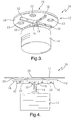
- Fig. 3 is a perspective view of the lower side of one embodiment of a motor and hub of a disc operating device;
- Fig. 4 is a profile view of the motor and hub shown in Fig. 3 with a disc positioned on the hub;
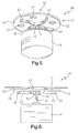
- Fig. 5 is a perspective view of the lower side of one embodiment of a motor and hub of a disc operating device;
- Fig. 6 is a profile view of the motor and hub shown in Fig. 5 with a disc positioned on the hub.
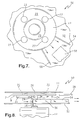
- Fig. 7 is an overhead view of one embodiment of a disc operating device including the hub shown in Figs. 1 and 2, an optical reading device, and a baffle system; and
- Fig. 8 is a profile view of the disc operating device shown in Fig. 7.
- Corresponding reference characters indicate corresponding parts throughout the several views. Although the drawings represent embodiments of the present invention, the drawings are not necessarily to scale and certain features may be exaggerated in order to better illustrate and explain the present invention. The exemplifications set out herein illustrate embodiments of the invention in several forms and such exemplification is not to be construed as limiting the scope of the invention in any manner.
- The embodiments discussed below are not intended to be exhaustive or limit the invention to the precise forms disclosed in the following detailed description. Rather, the embodiments are chosen and described so that others skilled in the art may utilize their teachings.
- One embodiment of
disc operating device 10 is shown in Figs. 1 and 2.Disc operating device 10 includesmotor 14 andhub 12.Motor 14 is supported by a frame (not shown) indisc operating device 10.Motor 14 is attached to a controller (not shown) and includesshaft 16.Shaft 16 is coupled tobase 19 ofhub 12.Hub 12 includesupper surface 20 andlower surface 18.Vanes 24 are coupled tolower surface 18 and extend radially outward frombase 19. Raisedportion 26 is formed onupper surface 20 ofhub 12. Hub 12 also includes fourapertures 22. In this embodiment, fourvanes 24 are perpendicular tolower surface 18 ofhub 12. Also, in this embodiment,hub 12 is formed from plastic, however steel, aluminum, or any other suitable material may be used. In other embodiments, more or fewer vanes may be used. Similarly, in other embodiments, more or fewer apertures may be used. - As shown in Fig. 2, disc 11 is supported by raised
portion 26 ofhub 12. In operation,motor 14 is actuated by a controller whendisc operating device 10 is used.Motor 14 rotatesshaft 16 which rotateshub 12 and disc 11. A reader, such asoptical reading device 58 shown in Figs. 7 and 8, supported by the frame, such asframe 52 shown in Fig. 7 and 8, reads information stored on disc 11. In an alternative embodiment, a recorder or writing device is used to store information on disc 11. As should be understood from the foregoing, the reader or writer could be an optical reader/writer, a magnetic reader/writer, or any other suitable device. - In most disc operating devices the disc is rotated at relatively high speed. For example, a typical CD player motor spins a CD at about 5500 revolutions per minute (RPM). Rotating
hub 12 to rotate disc 11 causesvanes 24 to act as an internal fan for disc 11 anddisc operating device 10. Vanes 24 act to pull air between disc 11 andhub 12 throughapertures 22. The air flow created byvanes 24 cools the disc 11 and/or internal components ofdisc operating device 10. Vanes 24 may cooldisc operating device 10 enough that an axial fan such as that discussed above is not necessary. Alternatively,vanes 24 may have a curved or angled shape (e.g.. Figs. 3-4 and 5-6 or other configurations (not shown) for directing air in other directions). - Another embodiment of a disc operating device is shown in Figs. 3 and 4.
Disc operating device 30 is substantially similar todisc operating device 10 in Figs. 1 and 2 with the exception that vanes 24 have been replaced byvanes 32.Vanes 32 are coupled tolower surface 18 ofhub 12 at an angle less than 90 degrees compared tovanes 24 which were perpendicularly coupled tolower surface 18. The slight tilting ofvanes 32 may promote more air flow throughdisc operating device 30 thanvanes 24. It should be understood thatvanes 32 could be coupled tolower surface 18 at any desired angle. - Another embodiment of a disc operating device is shown in Figs. 5 and 6.
Disc operating device 40 is substantially similar todisc operating device 10 in Figs. 1 and 2 with the exception that vanes 24 have been replaced byvanes 42.Vanes 42 are coupled tolower surface 18 ofhub 12 at an angle of about 90 degrees.Vanes 42 include a curved portion or surface 44 that may promote more air flow throughdisc operating device 40 thanvanes 24. In other embodiments (not shown),vanes 42 may include multiple curved portions and may be angled similar tovanes 32 in Figs. 3 and 4. - Another embodiment of a disc operating device is shown in Figs. 7 and 8.
Disc operating device 50 includesmotor 14 andhub 12 of the embodiment shown in Fig. 1.Disc operating device 50 also includesframe 52, baffles 54 and 56, andoptical reading device 58.Optical reading device 58 moves inward and outward across thebottom surface 18 of disc 11 toward the center of disc 11 as it rotates and "reads" the information stored on disc 11. In operation,optical reading device 58 and disc 11 may increase in temperature. -
Frame 52 includes an aperture through whichshaft 16 ofmotor 14 extends.Frame 52 is generally rigid and may support other components ofdisc operating system 50. Baffles 54 and 56 are coupled to frame 52 and extend outwardly from theaperture surrounding shaft 16. Baffles 54 and 56 extend upwardly fromframe 52 to a position close tovanes 24 ofhub 12. As described above, as disc 11 rotates,vanes 24 onbottom surface 18 ofhub 12 create air movement to cool disc 11 and/ordisc operating device 50. Baffles 54 and 56 are positioned onframe 52 to form a tunnel extending outwardly to direct airflow generated byvanes 24 ofhub 12 towardoptical reading device 58 and the portion ofbottom surface 18 adjacentoptical reading device 58. Whilevanes 24 shown in Figs. 1 and 2 have been used in this embodiment, the vane configurations shown in Figs. 3-6 may also be used withbaffles - While this invention has been described as having an exemplary design, the present invention may be further modified within the spirit and scope of this disclosure. This application is therefore intended to cover any variations, uses, or adaptations of the invention using its general principles. Further, this application is intended to cover such departures from the present disclosure as come within known or customary practice in the art to which this invention pertains.
Claims (23)
- A disc player (50) for playing at least one of a compact disc (11), a digital video disc, and a laser disc, the disc player (50) comprising:a frame (52);a motor (14) supported by the frame (52) and configured to rotate the disc (11);a hub (12) coupled to the motor (14) and configured to support the disc(11), the hub (12) including an upper surface (20) adjacent to the disc (11) and a lower surface (18), the lower surface (18) including a vane (24) extending downward, the vane (24) configured to cool at least one of the disc (11) and the disc player (50); anda reader (58) supported by the frame (52) and configured to read the disc (11).
- The disc player (50) of claim 1, further comprising a recorder configured to record information on the disc (11).
- The disc player (50) of claim 1, wherein the hub (12) is constructed of plastic.
- The disc player (50) of claim 1, wherein the hub (12) includes an off-center aperture (22).
- The disc player (50) of claim 1, wherein the hub (12) includes a plurality of vanes (24).
- The disc player (50) of claim 1, wherein the vane (24) is substantially perpendicular to the lower surface (18).
- The disc player (50) of claim 1, wherein the vane (24) is coupled to the hub (12) at an angle less than 90 degrees.
- The disc player (50) of claim 1, wherein hub (12) includes a center and the vane (24) extends radially outward from the center of the hub (12)
- The disc player (50) of claim 1, wherein the vane (24) includes a curved portion.
- The disc player (50) of claim 1, wherein the upper surface (20) of the hub (12) includes a raised center section (26) configured to support the disc (11).
- The disc player (50) of claim 1, further comprising first and second baffles (54, 56) coupled to the frame (52) and configured to direct airflow toward the reader (58).
- A method of cooling internal components of a disc operating apparatus (50), the method comprising the steps of:providing a frame (52), a motor (14) supported by the frame (52), and a hub (12) coupled to the motor (14) and configured to support a disc (11), the hub (12) including an upper surface (20) adjacent to the disc (11) and a lower surface (18), the lower surface (18) including a vane (24) extending downward, and a reader (58) supported by the frame (52) and configured to read the disc (11); andactuating the motor (14) to rotate the hub (12).
- The method of claim 12, wherein the providing step includes having a hub (12) including a plurality of vanes (24).
- The method of claim 12, wherein the providing step includes having a hub (12) including a plurality of off-center apertures (22) configured to promote airflow between the disc (11) and the hub (12).
- The method of claim 12, further comprising the step of providing a baffle (54) configured to channel airflow toward the reader (58), the baffle (54) positioned on the frame (52) between the hub (12) and the motor (14).
- A hub (12) for a disc operating apparatus (50), the hub (12) configured to support and rotate a disc (11) positioned on the hub (12), the hub (12) including:a first surface (20) configured to support the disc (11);a second surface (18) opposing the first surface (20); anda plurality of vanes (24) coupled to the second surface (18).
- The hub (12) of claim 16, wherein the hub (12) is constructed of plastic.
- The hub (12) of claim 16, wherein the hub (12) includes a plurality of off-center apertures (22).
- The hub (12) of claim 16, further comprising a raised central portion (26) on the first surface (20).
- The hub (12) of claim 16, wherein a first vane (24) of the plurality of vanes (24) defines a first axis and a second vane (24) of the plurality of vanes (24) defines a second axis, the first axis perpendicular to the second axis.
- The hub (12) of claim 16, wherein each of the plurality of vanes (24) has a curved profile.
- A disc player (50) for playing at least one of a compact disc (11), a digital video disc, and a laser disc, the disc player (50) comprising:a motor (14) configured to rotate the disc (11);a hub (12) coupled to the motor (14) and configured to support the disc (11), the hub (12) including an upper surface (20) adjacent to the disc (11) and a lower surface (18), the lower surface (18) including a vane (24) extending downward, the vane (24) configured to cool the disc player (50);a frame (52) positioned adjacent the lower surface (18) of the hub (12), the frame (52) including a first baffle (54) configured to direct airflow to cool at least one of the disc (11) and the disc player (50); anda reader (58) supported by the frame (52) and configured to read the disc (11).
- The disc player (50) of claim 22, wherein the frame (52) includes a second baffle (56) configured to cooperate with the first baffle (54) to form a channel, the channel configured to direct airflow toward the reader (58).
Applications Claiming Priority (1)
| Application Number | Priority Date | Filing Date | Title |
|---|---|---|---|
| US11/214,634 US7334243B2 (en) | 2005-08-30 | 2005-08-30 | Vane integration into motor hub to enhance CD cooling |
Publications (2)
| Publication Number | Publication Date |
|---|---|
| EP1760721A2 true EP1760721A2 (en) | 2007-03-07 |
| EP1760721A3 EP1760721A3 (en) | 2008-12-17 |
Family
ID=37019456
Family Applications (1)
| Application Number | Title | Priority Date | Filing Date |
|---|---|---|---|
| EP06076603A Withdrawn EP1760721A3 (en) | 2005-08-30 | 2006-08-21 | Vane integration into motor hub to enhance CD cooling |
Country Status (2)
| Country | Link |
|---|---|
| US (1) | US7334243B2 (en) |
| EP (1) | EP1760721A3 (en) |
Families Citing this family (11)
| Publication number | Priority date | Publication date | Assignee | Title |
|---|---|---|---|---|
| US6409242B1 (en) * | 2000-11-14 | 2002-06-25 | Chung L. Chang | Flat thin screen T/V monitor automotive roof mount |
| US7044546B2 (en) * | 2002-08-14 | 2006-05-16 | Johnson Safety, Inc. | Headrest-mounted monitor |
| US6871356B2 (en) * | 2002-10-28 | 2005-03-22 | Johnson Safety, Inc. | Mobile video system |
| US7812784B2 (en) * | 2005-11-02 | 2010-10-12 | Chung Lung Chang | Headrest mounted entertainment system |
| US7758117B2 (en) * | 2005-11-02 | 2010-07-20 | Chung Lung Chang | Headrest-mounted entertainment systems |
| US7591508B2 (en) * | 2005-11-02 | 2009-09-22 | Chung Lung Chang | Headrest mounted entertainment system |
| US7762627B2 (en) | 2005-11-02 | 2010-07-27 | Chung Lung Chang | Headrest-mounted entertainment systems |
| US8388060B2 (en) * | 2007-04-16 | 2013-03-05 | Chung Lung Chang | Headrest-mounted entertainment systems |
| US8345377B2 (en) * | 2009-12-29 | 2013-01-01 | Hgst, Netherlands B.V. | Aerodynamic device directing pressurized airflow to ports in the device for aerostatic sealing in a hard disk drive(HDD) |
| USD675238S1 (en) * | 2010-11-19 | 2013-01-29 | Launius Jr William E | Outer hub shaver |
| JP5767562B2 (en) * | 2011-10-31 | 2015-08-19 | ミネベア株式会社 | Disc clamp device |
Family Cites Families (16)
| Publication number | Priority date | Publication date | Assignee | Title |
|---|---|---|---|---|
| US4101945A (en) * | 1976-09-07 | 1978-07-18 | Sycor, Inc. | Drive spindle assembly for disc file |
| US4194225A (en) * | 1978-06-06 | 1980-03-18 | International Memories, Inc. | Housing for disk drive unit |
| US4369475A (en) * | 1979-01-26 | 1983-01-18 | Priam | Enclosed disc drive with improved air flow |
| JPS5984386A (en) * | 1982-11-08 | 1984-05-16 | Hitachi Ltd | magnetic disk device |
| JPS59157880A (en) * | 1983-02-25 | 1984-09-07 | Sharp Corp | Information disk recording and reproducing device |
| US4488193A (en) * | 1983-03-30 | 1984-12-11 | International Business Machines Corporation | Closed loop cooling system for disk file with heat exchanger integral with baseplate |
| US4633349A (en) * | 1984-07-23 | 1986-12-30 | International Business Machines Corporation | Disk drive air filter assembly |
| JPS62129992A (en) * | 1985-11-30 | 1987-06-12 | Toshiba Corp | Floppy disk device |
| JPS62175990A (en) * | 1986-01-29 | 1987-08-01 | Mitsubishi Electric Corp | Reproducing device for recording disk |
| US4873594A (en) * | 1988-04-18 | 1989-10-10 | Magnetic Peripherals Inc. | Disk spacer ring having air pumps |
| US5486962A (en) * | 1994-10-12 | 1996-01-23 | International Business Machines Corporation | Integral hub and disk clamp for a disk drive storage device |
| JPH08339623A (en) * | 1995-06-14 | 1996-12-24 | Matsushita Electric Ind Co Ltd | Disc player |
| KR19980015100A (en) * | 1996-08-20 | 1998-05-25 | 이형도 | Air cleaning method and apparatus of hard disk drive |
| US6359856B2 (en) * | 1996-12-31 | 2002-03-19 | Compaq Computer Corporation | Data storage disc drive apparatus with integral forced air cooling capability |
| KR100459699B1 (en) * | 2002-02-14 | 2004-12-04 | 삼성전자주식회사 | Hard disk drive having air pumping groove |
| KR100468721B1 (en) * | 2002-03-25 | 2005-01-29 | 삼성전자주식회사 | Hard disk drive having an air flow accelerating device |
-
2005
- 2005-08-30 US US11/214,634 patent/US7334243B2/en not_active Expired - Fee Related
-
2006
- 2006-08-21 EP EP06076603A patent/EP1760721A3/en not_active Withdrawn
Also Published As
| Publication number | Publication date |
|---|---|
| US20070050794A1 (en) | 2007-03-01 |
| EP1760721A3 (en) | 2008-12-17 |
| US7334243B2 (en) | 2008-02-19 |
Similar Documents
| Publication | Publication Date | Title |
|---|---|---|
| US7334243B2 (en) | Vane integration into motor hub to enhance CD cooling | |
| KR100296474B1 (en) | Apparatus and method for improving cooling of coils for voice coil motors in hard disks | |
| JP2006318519A (en) | Magnetic disk unit | |
| KR100716905B1 (en) | Spindle motor | |
| JP4183985B2 (en) | Optical disk device | |
| US7281257B2 (en) | Cooling device used in an optical recording and/or reproducing apparatus | |
| JP2000231782A (en) | Disk device and heat radiation method thereof | |
| US7526779B2 (en) | Optical disk apparatus | |
| US8929025B2 (en) | Clamping device for a rotatable component of a machine including a balance hole configured to confine a counterweight | |
| US7441257B2 (en) | Method and apparatus for cooling a compact disc | |
| KR100518823B1 (en) | Heat radiating apparatus of optical disk drive | |
| JPS6057154B2 (en) | disk pack | |
| JPH08279242A (en) | Recording and / or reproducing apparatus motor and spindle motor | |
| JP2005353114A (en) | Disk unit | |
| JP4276607B2 (en) | Disc tray and disc unit | |
| JP2007172744A (en) | Disk drive | |
| JP4200013B2 (en) | Magnetic disk unit | |
| KR101104024B1 (en) | Turntable of spindle motor | |
| KR200205331Y1 (en) | Disc tray of disc player | |
| JP2005339736A (en) | Optical disk device | |
| JP4186936B2 (en) | Optical disk device | |
| KR100926937B1 (en) | Optical disk drive unit | |
| JP2007257724A (en) | Disk drive | |
| KR20050076305A (en) | A pickup-unit cooling device for disk drive | |
| US20080155578A1 (en) | Optical Disk Drive Unit Having a Cooling Device |
Legal Events
| Date | Code | Title | Description |
|---|---|---|---|
| PUAI | Public reference made under article 153(3) epc to a published international application that has entered the european phase |
Free format text: ORIGINAL CODE: 0009012 |
|
| AK | Designated contracting states |
Kind code of ref document: A2 Designated state(s): AT BE BG CH CY CZ DE DK EE ES FI FR GB GR HU IE IS IT LI LT LU LV MC NL PL PT RO SE SI SK TR |
|
| AX | Request for extension of the european patent |
Extension state: AL BA HR MK YU |
|
| PUAL | Search report despatched |
Free format text: ORIGINAL CODE: 0009013 |
|
| AK | Designated contracting states |
Kind code of ref document: A3 Designated state(s): AT BE BG CH CY CZ DE DK EE ES FI FR GB GR HU IE IS IT LI LT LU LV MC NL PL PT RO SE SI SK TR |
|
| AX | Request for extension of the european patent |
Extension state: AL BA HR MK RS |
|
| RIC1 | Information provided on ipc code assigned before grant |
Ipc: G11B 17/028 20060101ALI20081113BHEP Ipc: G11B 33/14 20060101AFI20060929BHEP |
|
| 17P | Request for examination filed |
Effective date: 20090617 |
|
| 17Q | First examination report despatched |
Effective date: 20090715 |
|
| AKX | Designation fees paid |
Designated state(s): AT BE BG CH CY CZ DE DK EE ES FI FR GB GR HU IE IS IT LI LT LU LV MC NL PL PT RO SE SI SK TR |
|
| STAA | Information on the status of an ep patent application or granted ep patent |
Free format text: STATUS: THE APPLICATION IS DEEMED TO BE WITHDRAWN |
|
| 18D | Application deemed to be withdrawn |
Effective date: 20100126 |