EP1760537A2 - Drive control unit, drive control method and image forming apparatus - Google Patents
Drive control unit, drive control method and image forming apparatus Download PDFInfo
- Publication number
- EP1760537A2 EP1760537A2 EP06017862A EP06017862A EP1760537A2 EP 1760537 A2 EP1760537 A2 EP 1760537A2 EP 06017862 A EP06017862 A EP 06017862A EP 06017862 A EP06017862 A EP 06017862A EP 1760537 A2 EP1760537 A2 EP 1760537A2
- Authority
- EP
- European Patent Office
- Prior art keywords
- driving parts
- speed
- profiles
- speed fluctuation
- speeds
- Prior art date
- Legal status (The legal status is an assumption and is not a legal conclusion. Google has not performed a legal analysis and makes no representation as to the accuracy of the status listed.)
- Granted
Links
- 238000000034 method Methods 0.000 title claims description 25
- 238000012546 transfer Methods 0.000 claims description 42
- 239000003086 colorant Substances 0.000 description 22
- 238000010586 diagram Methods 0.000 description 18
- 230000032258 transport Effects 0.000 description 13
- 230000015572 biosynthetic process Effects 0.000 description 4
- 238000012937 correction Methods 0.000 description 3
- 230000032683 aging Effects 0.000 description 1
- 238000013459 approach Methods 0.000 description 1
- 239000000470 constituent Substances 0.000 description 1
- 238000007796 conventional method Methods 0.000 description 1
- 239000000284 extract Substances 0.000 description 1
- 238000012986 modification Methods 0.000 description 1
- 230000004048 modification Effects 0.000 description 1
Images





Classifications
-
- G—PHYSICS
- G03—PHOTOGRAPHY; CINEMATOGRAPHY; ANALOGOUS TECHNIQUES USING WAVES OTHER THAN OPTICAL WAVES; ELECTROGRAPHY; HOLOGRAPHY
- G03G—ELECTROGRAPHY; ELECTROPHOTOGRAPHY; MAGNETOGRAPHY
- G03G15/00—Apparatus for electrographic processes using a charge pattern
- G03G15/50—Machine control of apparatus for electrographic processes using a charge pattern, e.g. regulating differents parts of the machine, multimode copiers, microprocessor control
- G03G15/5008—Driving control for rotary photosensitive medium, e.g. speed control, stop position control
-
- G—PHYSICS
- G03—PHOTOGRAPHY; CINEMATOGRAPHY; ANALOGOUS TECHNIQUES USING WAVES OTHER THAN OPTICAL WAVES; ELECTROGRAPHY; HOLOGRAPHY
- G03G—ELECTROGRAPHY; ELECTROPHOTOGRAPHY; MAGNETOGRAPHY
- G03G2215/00—Apparatus for electrophotographic processes
- G03G2215/00025—Machine control, e.g. regulating different parts of the machine
- G03G2215/00071—Machine control, e.g. regulating different parts of the machine by measuring the photoconductor or its environmental characteristics
- G03G2215/00075—Machine control, e.g. regulating different parts of the machine by measuring the photoconductor or its environmental characteristics the characteristic being its speed
Definitions
- the present invention generally relates to drive control units, drive control methods and image forming apparatuses, and more particularly to a drive control unit and a drive control method for controlling speeds of a plurality of driving parts, and an image forming apparatus which employs such a drive control unit or drive control method.
- the intermediate transfer method forms a toner image on one photoconductive drum, one color at a time, and obtains the full color image by successively transferring the toner images of different colors on a transfer member.
- the tandem method arranged a plurality of photoconductive drums in parallel, forms the toner image of one color at each photoconductive drum, and obtains the full color image by successively transferring the toner images of different colors on the transfer member which successively passes the plurality of photoconductive drums. According to the tandem method, it is possible to carry out a high-speed image formation by operating the plurality of photoconductive drums approximately at the same time in synchronism with each other.
- the tandem method overlaps the toner images of the different colors, the plurality of photoconductive drums must rotate without flutter and in accurate synchronism with each other.
- the rotational speeds of the photoconductive drums are controlled independently so as to match the toner images of different colors that are overlapped.
- the tandem method can form the full color image without registration error of each of the colors (for example, black, yellow, magenta and cyan) if the rotational speeds of the plurality of photoconductive drums are all constant.
- the plurality of photoconductive drums are controlled independently, it is difficult to perfectly match the rotational speeds of the plurality of photoconductive drums.
- each photoconductive drum undergoes a fluctuation in its rotational speed that is peculiar to each photoconductive drum, due to eccentricity of a drum shaft and mounting error of a driving part and the photoconductive drum itself.
- the registration error in which the overlapping toner images of the different colors do not match on the transfer member is caused by the fluctuations in the rotational speeds of the plurality of photoconductive drums.
- FIG. 1 is a system block diagram showing an example of a drive control unit for the photoconductive drums.
- the drive control unit shown in FIG. 1 includes drive control systems for each of the colors, which are black, yellow, magenta and cyan in this particular case.
- the drive control system for black includes a control part 1K, a motor 2K, a photoconductive drum 3K and an encoder 4K.
- the motor 2K is coupled to the photoconductive drum 3K via a driving shaft and drives the photoconductive drum 3K.
- the encoder 4K detects the actual rotational speed of the motor 2K.
- the control part 1K controls the rotational speed of the motor 2K depending on a difference between a target rotational speed which is a constant value and the actual rotational speed that is fed back from the encoder 4K.
- the drive control system for yellow includes a control part 1Y, a motor 2Y, a photoconductive drum 3Y and an encoder 4Y.
- the drive control system for magenta includes a control part 1M, a motor 2M, a photoconductive drum 3M and an encoder 4M.
- the drive control system for cyan includes a control part 1C, a motor 2C, a photoconductive drum 3C and an encoder 4C.
- the drive control systems for yellow, magenta and cyan operate similarly to the drive control system for black described above.
- the drive control unit having the structure shown in FIG. 1 controls the rotational speed of the motor 2K depending on the difference between the constant target rotational speed and the actual rotational speed that are fed back from the encoder 4K, the photoconductive drum 3K undergoes a fluctuation in its rotational speed that is peculiar to the photoconductive drum 3K, due to the eccentricity of the drum shaft and the mounting error of the driving part and the photoconductive drum 3K itself.
- the registration error in which the overlapping toner images of the different colors do not match on the transfer member is caused by the fluctuations in the rotational speed of the photoconductive drum 3K.
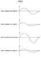
- FIG. 2 is a graph showing the actual speed fluctuations for one revolution of the photoconductive drums 3K, 3Y, 3M and 3C, wherein v denotes the rotational speed in arbitrary units and t denotes the time in arbitrary units.
- the fluctuation of the rotational speed for one revolution of each of the photoconductive drums 3K, 3Y, 3M and 3C will be referred to as a speed fluctuation profile.
- a Japanese Laid-Open Patent Application No.2002-72816 proposes a process of controlling the rotational speed of each photoconductive drum to approach the target rotational speed, by detecting the actual speed fluctuation profile of each photoconductive drum and adding data having an inverted phase (that is, a phase shifted by 180 degrees) with respect to the speed fluctuation profile, so as to correct the rotational speed of each photoconductive drum.
- Another and more specific object of the present invention is to provide a drive control unit, a drive control method and an image forming apparatus, which can reduce the registration error of the color image that is formed.
- Still another object of the present invention is to provide a drive control unit for controlling speeds of a plurality of driving parts based on a target speed, characterized by detecting means for detecting speed fluctuations of each of the driving parts when the speeds of the driving parts are controlled based on a common target speed; storage means for storing speed fluctuation profiles of each of the driving parts created based on the detected speed fluctuations; extracting means for extracting a speed fluctuation profile having a largest amplitude of the speed fluctuation profiles stores in the storage means; calculating means for calculating difference profiles of the driving parts, corresponding to differences between the extracted speed fluctuation profile and the speed fluctuation profiles of each of the driving parts; setting means for setting the difference profiles of the driving parts as new target speeds of the driving parts; and a control part configured to control the speeds of the driving parts based on the new target speeds.
- the drive control unit of the present invention it is possible to reduce the registration error of the color image that is formed.
- a further object of the present invention is to provide a drive control method for controlling speeds of a plurality of driving parts of an image forming apparatus based on a target speed, characterized by detecting speed fluctuations of each of the driving parts when the speeds of the driving parts are controlled based on a common target speed; extracting a speed fluctuation profile having a largest amplitude from speed fluctuation profiles of each of the driving parts created based on the detected speed fluctuations; calculating difference profiles of the driving parts, corresponding to differences between the extracted speed fluctuation profile and the speed fluctuation profiles of each of the driving parts; and setting the difference profiles of the driving parts as new target speeds of the driving parts, and controlling the speeds of the driving parts based on the new target speeds.
- the drive control method of the present invention it is possible to reduce the registration error of the color image that is formed.
- Another object of the present invention is to provide an image forming apparatus which forms toner images on a plurality of photoconductive drums and directly or indirectly transfers the toner images onto a recording medium to form a full color image thereon, characterized by a plurality of driving parts configured to independently control rotational speeds of corresponding photoconductive drums; and a drive control unit configured to control speeds of the plurality of driving parts based on a target speed, wherein the drive control unit comprises detecting means for detecting speed fluctuations of each of the driving parts when the speeds of the driving parts are controlled based on a common target speed; storage means for storing speed fluctuation profiles of each of the driving parts created based on the detected speed fluctuations; extracting means for extracting a speed fluctuation profile having a largest amplitude of the speed fluctuation profiles stores in the storage means; calculating means for calculating difference profiles of the driving parts, corresponding to differences between the extracted speed fluctuation profile and the speed fluctuation profiles of each of the driving parts; setting means for setting the difference profiles of the driving parts as new target speeds of the driving parts;
- FIG. 3 is a diagram showing a general structure of the image forming apparatus.
- the image forming apparatus shown in FIG. 3 has image forming parts 401Y, 401M, 401C and 401K for forming yellow, magenta, cyan and black images, respectively.
- the image forming parts 401Y, 401M, 401C and 401K are arranged in line along a transport belt 411 which transports a transfer member 410 which may be a sheet of paper or a suitable recording medium.
- the transport belt 411 is supported by a driving roller 412 which drives and revolves the transport belt 411, and a following roller 412 which follows the revolving the transport belt 411.
- the transport belt 411 is driven to revolve in a direction indicated by an arrow in FIG. 3 by the rotation of the driving roller 412.
- a paper supply tray 414 which accommodates the transfer members 410 is provided under the transport belt 411.
- the transfer members 410 accommodated within the paper supply tray 414 are fed starting from the top transfer member 410.
- the fed transfer member 410 is adhered on the transport belt 411 by electrostatic adhesion, and is transported to the yellow image forming part 401Y where the yellow image is formed.
- the yellow image forming part 401Y includes a photoconductive drum 402Y, a charger 403Y provided in a periphery of the photoconductive drum 402Y, a developing unit 405Y, a photoconductive body cleaner 406Y, a transfer unit 407Y, and an exposure unit 408 which irradiates laser modulated light 409Y corresponding to the yellow image.
- the surface of the photoconductive drum 402Y is uniformly charged by the charger 403Y, and the charged surface is then exposed by the laser modulated light 409Y of the exposure unit 408, corresponding to the yellow image, so as to form an electrostatic latent image.
- the electrostatic latent image is developed by the developing unit 405Y, so as to form a yellow toner image on the surface of the photoconductive drum 402Y.
- the yellow toner image is transferred onto the transfer member 410 by the transfer unit 407Y, at a transfer position where the photoconductive drum 402Y and the transfer member 410 on the transport belt 411 make contact, to thereby form a single color image, that is, the yellow image, on the transfer member 410.
- the residual toner on the surface of the photoconductive drum 402Y is cleaned by the photoconductive drum cleaner 406Y, so as to prepare for the next image formation in yellow.
- the transfer member 410 bearing the yellow image transferred thereon in the yellow image forming part 401Y is transported to the magenta image forming part 401M by the transport belt 411.
- the magenta image forming part 401M transfers a magenta toner image that is formed on the surface of the photoconductive drum 402M onto the transfer member 410, similarly to the image formation in the yellow image forming part 401Y, so as to overlap the yellow image.
- the transfer member 410 is further transported to the cyan image forming part 401C and the black image forming part 401K in this sequence, so as to sequentially transfer a cyan toner image and a black toner image that are formed on the surfaces of the corresponding photoconductive drums 402C and 402K onto the transfer member 410, similarly to the image formation in the yellow image forming part 401Y, so as to overlap the yellow and magenta images.
- the transfer member 410 passes the black image forming part 401K
- the transfer member 410 bearing the overlapping yellow, magenta, cyan and black images, that is, a full color image is separated from the transport belt 411 and supplied to a fixing unit 415.
- the fixing unit 415 fixes the full color image on the transfer member 410, and the transfer member 410 is thereafter ejected from the image forming apparatus.
- the image forming apparatus shown in FIG. 3 directly transfers the toner images from the photoconductive drums 402Y, 402M, 402C and 402K onto the transfer member 410.
- the photoconductive drums 402Y, 402M, 402C and 402K are driven by corresponding motors (not shown).
- the fluctuations in the rotational speeds of the photoconductive drums 402Y, 402M, 402C and 402K, peculiar to the photoconductive drums 402Y, 402M, 402C and 402K, are eliminated by drive control systems for each of the colors yellow, magenta, cyan and black, as will be described later.
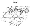
- FIG. 4 is a diagram generally showing a driving mechanism for the photoconductive drums.
- driving shafts 505 through 508 are provided to drive and rotate the photoconductive drums 402Y, 402M, 402C and 402K.
- brushless motors 509 through 512 are provided to drive and rotate the driving shafts 505 through 508 of the photoconductive drums 402Y, 402M, 402C and 402K.
- the rotational speeds of the brushless motors 509 through 512 are detected by corresponding encoders 513 through 516 that are provided on corresponding motor shafts of the brushless motors 509 through 512.
- FIG. 5 is a system block diagram showing an embodiment of the drive control unit according to the present invention.
- the drive control unit shown in FIG. 5 includes a black drive control system 10K, a yellow drive control system 10Y, a magenta drive control system 10M, a cyan drive control system 10C, a memory 11, a maximum speed fluctuation profile extracting part 12, a difference profile calculating part 13, and a target speed setting part 14.
- the black drive control system 10K, the yellow drive control system 10Y, the magenta drive control system 10M and the cyan drive control system 10C have the structure shown in FIG. 1.
- the black drive control system 10K includes a control part 1K, a motor 2K, a photoconductive drum 3K and an encoder 4K.
- the yellow drive control system 10Y includes a control part 1Y, a motor 2Y, a photoconductive drum 3Y and an encoder 4Y.
- the magenta drive control system 10M includes a control part 1M, a motor 2M, a photoconductive drum 3M and an encoder 4M
- the cyan drive control system 10C includes a control part 1C, a motor 2C, a photoconductive drum 3C and an encoder 4C.
- FIG. 6 is a flow chart for explaining the operation of the drive control unit.
- the drive control unit stores in the memory 11 a speed fluctuation profile for each of the colors yellow, magenta, cyan and black for the case where the rotational speeds of the photoconductive drums 402Y, 402M, 402C and 402K are controlled based on a common target rotational speed which is set in common with respect to each of the photoconductive drums 402Y, 402M, 402C and 402K.
- the black drive control system 10K detects the actual rotational speed of the motor 2K for the case where the rotational speed of the motor 2K is controlled by the control part 1K based on the common target rotational speed which is a constant value, and stores the fluctuation in the rotational speed of the motor 2K for one revolution of the photoconductive drum 3K in the memory 11 as the speed fluctuation profile.
- the yellow drive control system 10Y detects the actual rotational speed of the motor 2Y for the case where the rotational speed of the motor 2Y is controlled by the control part 1Y based on the common target rotational speed which is a constant value, and stores the fluctuation in the rotational speed of the motor 2Y for one revolution of the photoconductive drum 3Y in the memory 11 as the speed fluctuation profile.
- the magenta drive control system 10M and the cyan drive control system 10C store the speed fluctuation profiles for the photoconductive drums 3M and 3Y in the memory 11, similarly to the black drive control system 10K and the yellow drive control system 10Y.
- the maximum speed fluctuation profile extracting part 12 reads the speed fluctuation profiles of each of the yellow, magenta, cyan and black colors from the memory 11, and extracts the speed fluctuation profile having a largest amplitude. For example, in a case where the actual rotational speeds of the motors 2K, 2Y, 2M and 2C become as shown in FIG. 2 when the control parts 1K, 1Y, 2M and 1C control the rotational speeds of the motors 2K, 2Y, 2M and 2C based on the common target rotational speed which is a constant value, the speed fluctuation profile for magenta is extracted as the speed fluctuation profile having the largest amplitude.
- the maximum speed fluctuation profile extracting part 12 supplies the extracted speed fluctuation profile to the difference profile calculating part 13.
- the difference profile calculating part 13 reads the speed fluctuation profiles of each of the colors yellow, magenta, cyan and black, and calculates a difference profile between the speed fluctuation profile having the largest amplitude and supplied from the maximum speed fluctuation profile extracting part 12 and each of the speed fluctuation profiles of the colors yellow, magenta, cyan and black.
- the difference profile calculating part 13 subtracts each of the speed fluctuation profiles of the colors yellow, magenta, cyan and black stored in the memory 11 from the speed fluctuation profile having the largest amplitude and supplied from the maximum speed fluctuation profile extracting part 12, so as to obtain the difference profiles for each of the colors yellow, magenta, cyan and black.
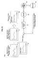
- FIG. 7 is a diagram for explaining the calculation of a black difference profile and the setting of a new target rotational speed.
- FIG. 8 is a diagram for explaining the calculation of a yellow difference profile and the setting of the new target rotational speed.
- FIG. 9 is a diagram for explaining the calculation of a magenta difference profile and the setting of the new target rotational speed.
- FIG. 10 is a diagram for explaining the calculation of a cyan difference profile and the setting of the new target rotational speed.
- FIGS. 7 through 10 show the calculation of the difference profiles and the setting of the new target rotational speed for the case where the speed fluctuation profile for magenta is extracted as the speed fluctuation profile having the largest amplitude.
- the difference profile calculating part 13 subtracts a speed fluctuation profile 22 for black stored in the memory 11 from an extracted speed fluctuation profile 21 for magenta, so as to calculate a difference profile 23 for black.
- the difference profile calculating part 13 subtracts a speed fluctuation profile 25 for yellow stored in the memory 11 from the extracted speed fluctuation profile 21 for magenta, so as to calculate a difference profile 26 for yellow.
- the difference profile calculating part 13 subtracts a speed fluctuation profile 28 for magenta stored in the memory 11 from the extracted speed fluctuation profile 21 for magenta, so as to calculate a difference profile 29 for magenta.
- the extracted speed fluctuation profile 21 and the subtracted speed fluctuation profile 28 are the same.
- the difference profile calculating part 13 subtracts a speed fluctuation profile 31 for cyan stored in the memory 11 from the extracted speed fluctuation profile 21 for magenta, so as to calculate a difference profile 32 for cyan.
- the difference profile calculating part 13 supplies the calculated difference profiles 23, 26, 29 and 32 for the colors black, yellow, magenta and cyan to the target speed setting part 14. Then, in a step S4 shown in FIG. 6, the target speed setting part 14 sets the difference profiles 23, 26, 29 and 32 for the colors black, yellow, magenta and cyan, supplied from the difference profile calculating part 13, as new target rotational speeds for the colors black, yellow, magenta and cyan.
- the target speed setting part 14 sets the difference profile 23 for black as the new target rotational speed for the black drive control system 10K.
- the target speed setting part 14 sets the difference profile 26 for yellow as the new target rotational speed for the yellow drive control system 10Y.
- the target speed setting part 14 sets the difference profile 29 for magenta as the new target rotational speed for the magenta drive control system 10M.
- the target speed setting part 14 sets the difference profile 32 for cyan as the new target rotational speed for the cyan drive control system 10C.
- the drive control unit sets the difference profiles 23, 26, 29 and 32 for the colors black, yellow, magenta and cyan as the new target rotational speeds for the black, yellow, magenta and cyan drive control systems 10K, 10Y, 10M and 10C, so as to include in the rotational speeds of the photoconductive drums 3K, 3Y and 3C for the colors other than magenta the same fluctuation in the rotational speed as the photoconductive drum 3M for magenta.
- the fluctuations in the rotational speeds of the photoconductive drums 3K, 3Y and 3C become larger when compared to the conventional case, but under a condition where the distance between two mutually adjacent photoconductive drums is equal to the circumference of the photoconductive drum and the moving speed of the transport belt (including the intermediate transfer belt in the case of the image forming apparatus having the intermediate transfer belt) is equal to the rotational speed at the outer periphery of the photoconductive drum, the relative speed of the photoconductive drum at the transfer position for each color becomes zero with respect to the transport belt. Therefore, the effects of the fluctuations in the rotational speeds of the photoconductive drums will not appear as the registration error in the full color image that is finally formed on the transfer member.
- the drive control unit of the present invention In order to carry out the control by the drive control unit of the present invention, it is necessary to once control the rotational speed of the photoconductive drums for each of the colors to the common target rotational speed which is a constant value. Such a control by the drive control unit may be carried out at timings including when the power is supplied to the image forming apparatus, when a paper jam is generated and the like. When the control is carried out by the drive control unit at such timings, the data related to the fluctuation in the rotational speed of each of the photoconductive drums may be stored in a recording medium such as the memory 11.
- FIG. 11 is a system block diagram showing another embodiment of the drive control unit according to the present invention.
- those parts which are the same as those corresponding parts in FIGS. 7 through 10 are designated by the same reference numerals, and a description thereof will be omitted.
- the means for matching the rotational speeds of the photoconductive drums of each of the colors to the rotational speed of the photoconductive drum having the largest fluctuation in the rotational speed may be realized by a gain correction of a correction value detecting part 50 for detecting correction values for the gains of the control parts 1K, 1Y, 1M and 1C.
- the speed fluctuation profile of each photoconductive drum corresponding to the fluctuation in the rotational speed for one revolution of each photoconductive drum is detected.
- the speed fluctuation profile of the photoconductive drum having the largest fluctuation in the rotational speed is extracted, and the rotational speeds of the other photoconductive drums are controlled so as to match the extracted speed fluctuation profile.
- the drive control unit of the present invention can match the rotational speeds of the plurality of photoconductive drums, and reduce the registration error of the full color image that is finally formed on the transfer member by the plurality of photoconductive drums.
- the drive control unit of the present invention if the image forming apparatus is used for a long period of time and the constituent elements of the image forming apparatus deteriorate due to aging, the speed fluctuation profiles of the photoconductive drums are matched to the speed fluctuation profile of the photoconductive drum having the largest speed fluctuation. For this reason, the registration error will not be generated even if the so-called banding occurs.
- the banding refers to a band-shaped tone inconsistency that appears in a halftone portion of the image. The banding occurs when the pitch of the halftone dots changes due to the fluctuation in the speed of the mechanical system, for example, and often occurs in the case of the image forming apparatus employing the spot exposure scan system.
Landscapes
- Engineering & Computer Science (AREA)
- Microelectronics & Electronic Packaging (AREA)
- Physics & Mathematics (AREA)
- General Physics & Mathematics (AREA)
- Control Or Security For Electrophotography (AREA)
- Color Electrophotography (AREA)
- Fax Reproducing Arrangements (AREA)
- Control Of Multiple Motors (AREA)
Abstract
Description
- The present invention generally relates to drive control units, drive control methods and image forming apparatuses, and more particularly to a drive control unit and a drive control method for controlling speeds of a plurality of driving parts, and an image forming apparatus which employs such a drive control unit or drive control method.
- Conventionally, as methods of forming color images, there are the intermediate transfer method and the tandem method. The intermediate transfer method forms a toner image on one photoconductive drum, one color at a time, and obtains the full color image by successively transferring the toner images of different colors on a transfer member. The tandem method arranged a plurality of photoconductive drums in parallel, forms the toner image of one color at each photoconductive drum, and obtains the full color image by successively transferring the toner images of different colors on the transfer member which successively passes the plurality of photoconductive drums. According to the tandem method, it is possible to carry out a high-speed image formation by operating the plurality of photoconductive drums approximately at the same time in synchronism with each other.
- Since the tandem method overlaps the toner images of the different colors, the plurality of photoconductive drums must rotate without flutter and in accurate synchronism with each other. Hence, in the tandem method which uses the plurality of photoconductive drums (for example, four photoconductive drums in order to obtain the full color image), the rotational speeds of the photoconductive drums are controlled independently so as to match the toner images of different colors that are overlapped.
- The tandem method can form the full color image without registration error of each of the colors (for example, black, yellow, magenta and cyan) if the rotational speeds of the plurality of photoconductive drums are all constant. However, since the plurality of photoconductive drums are controlled independently, it is difficult to perfectly match the rotational speeds of the plurality of photoconductive drums.
- In other words, in the case of the tandem method, even if a target rotational speed is set with respect to each of the plurality of photoconductive drums, each photoconductive drum undergoes a fluctuation in its rotational speed that is peculiar to each photoconductive drum, due to eccentricity of a drum shaft and mounting error of a driving part and the photoconductive drum itself. As a result, the registration error in which the overlapping toner images of the different colors do not match on the transfer member is caused by the fluctuations in the rotational speeds of the plurality of photoconductive drums.
- FIG. 1 is a system block diagram showing an example of a drive control unit for the photoconductive drums. The drive control unit shown in FIG. 1 includes drive control systems for each of the colors, which are black, yellow, magenta and cyan in this particular case. The drive control system for black includes a
control part 1K, amotor 2K, aphotoconductive drum 3K and anencoder 4K. - The
motor 2K is coupled to thephotoconductive drum 3K via a driving shaft and drives thephotoconductive drum 3K. Theencoder 4K detects the actual rotational speed of themotor 2K. In addition, thecontrol part 1K controls the rotational speed of themotor 2K depending on a difference between a target rotational speed which is a constant value and the actual rotational speed that is fed back from theencoder 4K. - The drive control system for yellow includes a
control part 1Y, amotor 2Y, aphotoconductive drum 3Y and anencoder 4Y. The drive control system for magenta includes acontrol part 1M, amotor 2M, aphotoconductive drum 3M and anencoder 4M. The drive control system for cyan includes acontrol part 1C, amotor 2C, aphotoconductive drum 3C and anencoder 4C. The drive control systems for yellow, magenta and cyan operate similarly to the drive control system for black described above. - However, even though the drive control unit having the structure shown in FIG. 1 controls the rotational speed of the
motor 2K depending on the difference between the constant target rotational speed and the actual rotational speed that are fed back from theencoder 4K, thephotoconductive drum 3K undergoes a fluctuation in its rotational speed that is peculiar to thephotoconductive drum 3K, due to the eccentricity of the drum shaft and the mounting error of the driving part and thephotoconductive drum 3K itself. As a result, the registration error in which the overlapping toner images of the different colors do not match on the transfer member is caused by the fluctuations in the rotational speed of thephotoconductive drum 3K. - In addition, in the drive control systems for yellow, magenta and cyan, the registration error is generated similarly to the drive control system for black. In other words, the rotational speeds for one revolution of the
photoconductive drums photoconductive drums photoconductive drums - A
Japanese Laid-Open Patent Application No.2002-72816 - However, according to the process proposed in the
Japanese Laid-Open Patent Application No.2002-72816 - Accordingly, it is a general object of the present invention to provide a novel and useful drive control unit, drive control method and image forming apparatus, in which the problems described above are suppressed.
- Another and more specific object of the present invention is to provide a drive control unit, a drive control method and an image forming apparatus, which can reduce the registration error of the color image that is formed.
- Still another object of the present invention is to provide a drive control unit for controlling speeds of a plurality of driving parts based on a target speed, characterized by detecting means for detecting speed fluctuations of each of the driving parts when the speeds of the driving parts are controlled based on a common target speed; storage means for storing speed fluctuation profiles of each of the driving parts created based on the detected speed fluctuations; extracting means for extracting a speed fluctuation profile having a largest amplitude of the speed fluctuation profiles stores in the storage means; calculating means for calculating difference profiles of the driving parts, corresponding to differences between the extracted speed fluctuation profile and the speed fluctuation profiles of each of the driving parts; setting means for setting the difference profiles of the driving parts as new target speeds of the driving parts; and a control part configured to control the speeds of the driving parts based on the new target speeds. According to the drive control unit of the present invention, it is possible to reduce the registration error of the color image that is formed.
- A further object of the present invention is to provide a drive control method for controlling speeds of a plurality of driving parts of an image forming apparatus based on a target speed, characterized by detecting speed fluctuations of each of the driving parts when the speeds of the driving parts are controlled based on a common target speed; extracting a speed fluctuation profile having a largest amplitude from speed fluctuation profiles of each of the driving parts created based on the detected speed fluctuations; calculating difference profiles of the driving parts, corresponding to differences between the extracted speed fluctuation profile and the speed fluctuation profiles of each of the driving parts; and setting the difference profiles of the driving parts as new target speeds of the driving parts, and controlling the speeds of the driving parts based on the new target speeds. According to the drive control method of the present invention, it is possible to reduce the registration error of the color image that is formed.
- Another object of the present invention is to provide an image forming apparatus which forms toner images on a plurality of photoconductive drums and directly or indirectly transfers the toner images onto a recording medium to form a full color image thereon, characterized by a plurality of driving parts configured to independently control rotational speeds of corresponding photoconductive drums; and a drive control unit configured to control speeds of the plurality of driving parts based on a target speed, wherein the drive control unit comprises detecting means for detecting speed fluctuations of each of the driving parts when the speeds of the driving parts are controlled based on a common target speed; storage means for storing speed fluctuation profiles of each of the driving parts created based on the detected speed fluctuations; extracting means for extracting a speed fluctuation profile having a largest amplitude of the speed fluctuation profiles stores in the storage means; calculating means for calculating difference profiles of the driving parts, corresponding to differences between the extracted speed fluctuation profile and the speed fluctuation profiles of each of the driving parts; setting means for setting the difference profiles of the driving parts as new target speeds of the driving parts; and control means for controlling the speeds of the driving parts based on the new target speeds. According to the image forming apparatus of the present invention, it is possible to reduce the registration error of the color image that is formed.
- Other objects and further features of the present invention will be apparent from the following detailed description when read in conjunction with the accompanying drawings.
-
- FIG. 1 is a system block diagram showing an example of a drive control unit for photoconductive drums;
- FIG. 2 is a graph showing actual speed fluctuations for one revolution of the photoconductive drums;
- FIG. 3 is a diagram showing a general structure of an image forming apparatus;
- FIG. 4 is a diagram generally showing a driving mechanism for the photoconductive drums;
- FIG. 5 is a system block diagram showing an embodiment of a drive control unit according to the present invention;
- FIG. 6 is a flow chart for explaining an operation of the drive control unit;
- FIG. 7 is a diagram for explaining the calculation of a black difference profile and the setting of a new target rotational speed;
- FIG. 8 is a diagram for explaining the calculation of a yellow difference profile and the setting of the new target rotational speed;
- FIG. 9 is a diagram for explaining the calculation of a magenta difference profile and the setting of the new target rotational speed;
- FIG. 10 is a diagram for explaining the calculation of a cyan difference profile and the setting of the new target rotational speed; and
- FIG. 11 is a system block diagram showing another embodiment of the drive control unit according to the present invention.
- A description will be given of embodiments of a drive control unit, a drive control method and an image forming apparatus according to the present invention, by referring to FIG. 3 and the subsequent figures.
- FIG. 3 is a diagram showing a general structure of the image forming apparatus. The image forming apparatus shown in FIG. 3 has
image forming parts image forming parts transport belt 411 which transports atransfer member 410 which may be a sheet of paper or a suitable recording medium. Thetransport belt 411 is supported by adriving roller 412 which drives and revolves thetransport belt 411, and a followingroller 412 which follows the revolving thetransport belt 411. Thetransport belt 411 is driven to revolve in a direction indicated by an arrow in FIG. 3 by the rotation of thedriving roller 412. - A
paper supply tray 414 which accommodates thetransfer members 410 is provided under thetransport belt 411. When forming an image, thetransfer members 410 accommodated within thepaper supply tray 414 are fed starting from thetop transfer member 410. The fedtransfer member 410 is adhered on thetransport belt 411 by electrostatic adhesion, and is transported to the yellowimage forming part 401Y where the yellow image is formed. - The yellow
image forming part 401Y includes aphotoconductive drum 402Y, acharger 403Y provided in a periphery of thephotoconductive drum 402Y, a developingunit 405Y, a photoconductive body cleaner 406Y, atransfer unit 407Y, and an exposure unit 408 which irradiates laser modulatedlight 409Y corresponding to the yellow image. - In the yellow
image forming part 401Y, the surface of thephotoconductive drum 402Y is uniformly charged by thecharger 403Y, and the charged surface is then exposed by the laser modulated light 409Y of the exposure unit 408, corresponding to the yellow image, so as to form an electrostatic latent image. The electrostatic latent image is developed by the developingunit 405Y, so as to form a yellow toner image on the surface of thephotoconductive drum 402Y. The yellow toner image is transferred onto thetransfer member 410 by thetransfer unit 407Y, at a transfer position where thephotoconductive drum 402Y and thetransfer member 410 on thetransport belt 411 make contact, to thereby form a single color image, that is, the yellow image, on thetransfer member 410. After the yellow image is transferred onto thetransfer member 410, the residual toner on the surface of thephotoconductive drum 402Y is cleaned by thephotoconductive drum cleaner 406Y, so as to prepare for the next image formation in yellow. - The
transfer member 410 bearing the yellow image transferred thereon in the yellowimage forming part 401Y is transported to the magentaimage forming part 401M by thetransport belt 411. The magentaimage forming part 401M transfers a magenta toner image that is formed on the surface of thephotoconductive drum 402M onto thetransfer member 410, similarly to the image formation in the yellowimage forming part 401Y, so as to overlap the yellow image. - The
transfer member 410 is further transported to the cyanimage forming part 401C and the blackimage forming part 401K in this sequence, so as to sequentially transfer a cyan toner image and a black toner image that are formed on the surfaces of the correspondingphotoconductive drums transfer member 410, similarly to the image formation in the yellowimage forming part 401Y, so as to overlap the yellow and magenta images. After thetransfer member 410 passes the blackimage forming part 401K, thetransfer member 410 bearing the overlapping yellow, magenta, cyan and black images, that is, a full color image, is separated from thetransport belt 411 and supplied to afixing unit 415. The fixingunit 415 fixes the full color image on thetransfer member 410, and thetransfer member 410 is thereafter ejected from the image forming apparatus. - The image forming apparatus shown in FIG. 3 directly transfers the toner images from the
photoconductive drums transfer member 410. However, it is of course possible to form the color image on an intermediate transfer body such as an intermediate transfer belt, and thereafter transfer the color image on the intermediate transfer body onto thetransfer member 410 in one operation. - In the image forming apparatus, the
photoconductive drums photoconductive drums photoconductive drums - FIG. 4 is a diagram generally showing a driving mechanism for the photoconductive drums. As shown in FIG. 4, driving
shafts 505 through 508 are provided to drive and rotate thephotoconductive drums brushless motors 509 through 512 are provided to drive and rotate the drivingshafts 505 through 508 of thephotoconductive drums brushless motors 509 through 512 are detected by correspondingencoders 513 through 516 that are provided on corresponding motor shafts of thebrushless motors 509 through 512. - FIG. 5 is a system block diagram showing an embodiment of the drive control unit according to the present invention. The drive control unit shown in FIG. 5 includes a black
drive control system 10K, a yellowdrive control system 10Y, a magentadrive control system 10M, a cyandrive control system 10C, amemory 11, a maximum speed fluctuationprofile extracting part 12, a differenceprofile calculating part 13, and a targetspeed setting part 14. - The black
drive control system 10K, the yellowdrive control system 10Y, the magentadrive control system 10M and the cyandrive control system 10C have the structure shown in FIG. 1. The blackdrive control system 10K includes acontrol part 1K, amotor 2K, aphotoconductive drum 3K and anencoder 4K. The yellowdrive control system 10Y includes acontrol part 1Y, amotor 2Y, aphotoconductive drum 3Y and anencoder 4Y. In addition, the magentadrive control system 10M includes acontrol part 1M, amotor 2M, aphotoconductive drum 3M and anencoder 4M, and the cyandrive control system 10C includes acontrol part 1C, amotor 2C, aphotoconductive drum 3C and anencoder 4C. - Next, a description will be given of an operation of the drive control unit shown in FIG. 5, by referring to FIG. 6. FIG. 6 is a flow chart for explaining the operation of the drive control unit. In a step S1, the drive control unit stores in the memory 11 a speed fluctuation profile for each of the colors yellow, magenta, cyan and black for the case where the rotational speeds of the
photoconductive drums photoconductive drums - For example, the black
drive control system 10K detects the actual rotational speed of themotor 2K for the case where the rotational speed of themotor 2K is controlled by thecontrol part 1K based on the common target rotational speed which is a constant value, and stores the fluctuation in the rotational speed of themotor 2K for one revolution of thephotoconductive drum 3K in thememory 11 as the speed fluctuation profile. - Similarly, the yellow
drive control system 10Y detects the actual rotational speed of themotor 2Y for the case where the rotational speed of themotor 2Y is controlled by thecontrol part 1Y based on the common target rotational speed which is a constant value, and stores the fluctuation in the rotational speed of themotor 2Y for one revolution of thephotoconductive drum 3Y in thememory 11 as the speed fluctuation profile. The magentadrive control system 10M and the cyandrive control system 10C store the speed fluctuation profiles for thephotoconductive drums memory 11, similarly to the blackdrive control system 10K and the yellowdrive control system 10Y. - In a step S2, the maximum speed fluctuation
profile extracting part 12 reads the speed fluctuation profiles of each of the yellow, magenta, cyan and black colors from thememory 11, and extracts the speed fluctuation profile having a largest amplitude. For example, in a case where the actual rotational speeds of themotors control parts motors profile extracting part 12 supplies the extracted speed fluctuation profile to the differenceprofile calculating part 13. - In a step S3, the difference
profile calculating part 13 reads the speed fluctuation profiles of each of the colors yellow, magenta, cyan and black, and calculates a difference profile between the speed fluctuation profile having the largest amplitude and supplied from the maximum speed fluctuationprofile extracting part 12 and each of the speed fluctuation profiles of the colors yellow, magenta, cyan and black. - For example, the difference
profile calculating part 13 subtracts each of the speed fluctuation profiles of the colors yellow, magenta, cyan and black stored in thememory 11 from the speed fluctuation profile having the largest amplitude and supplied from the maximum speed fluctuationprofile extracting part 12, so as to obtain the difference profiles for each of the colors yellow, magenta, cyan and black. - FIG. 7 is a diagram for explaining the calculation of a black difference profile and the setting of a new target rotational speed. FIG. 8 is a diagram for explaining the calculation of a yellow difference profile and the setting of the new target rotational speed. FIG. 9 is a diagram for explaining the calculation of a magenta difference profile and the setting of the new target rotational speed. FIG. 10 is a diagram for explaining the calculation of a cyan difference profile and the setting of the new target rotational speed.
- FIGS. 7 through 10 show the calculation of the difference profiles and the setting of the new target rotational speed for the case where the speed fluctuation profile for magenta is extracted as the speed fluctuation profile having the largest amplitude. In FIG. 7, the difference
profile calculating part 13 subtracts aspeed fluctuation profile 22 for black stored in thememory 11 from an extractedspeed fluctuation profile 21 for magenta, so as to calculate adifference profile 23 for black. - In FIG. 8, the difference
profile calculating part 13 subtracts aspeed fluctuation profile 25 for yellow stored in thememory 11 from the extractedspeed fluctuation profile 21 for magenta, so as to calculate adifference profile 26 for yellow. - In FIG. 9, the difference
profile calculating part 13 subtracts aspeed fluctuation profile 28 for magenta stored in thememory 11 from the extractedspeed fluctuation profile 21 for magenta, so as to calculate adifference profile 29 for magenta. In this particular case, the extractedspeed fluctuation profile 21 and the subtractedspeed fluctuation profile 28 are the same. - In FIG. 10, the difference
profile calculating part 13 subtracts aspeed fluctuation profile 31 for cyan stored in thememory 11 from the extractedspeed fluctuation profile 21 for magenta, so as to calculate adifference profile 32 for cyan. - The difference
profile calculating part 13 supplies the calculated difference profiles 23, 26, 29 and 32 for the colors black, yellow, magenta and cyan to the targetspeed setting part 14. Then, in a step S4 shown in FIG. 6, the targetspeed setting part 14 sets the difference profiles 23, 26, 29 and 32 for the colors black, yellow, magenta and cyan, supplied from the differenceprofile calculating part 13, as new target rotational speeds for the colors black, yellow, magenta and cyan. - In FIG. 7, the target
speed setting part 14 sets thedifference profile 23 for black as the new target rotational speed for the blackdrive control system 10K. In FIG. 8, the targetspeed setting part 14 sets thedifference profile 26 for yellow as the new target rotational speed for the yellowdrive control system 10Y. In FIG. 9, the targetspeed setting part 14 sets thedifference profile 29 for magenta as the new target rotational speed for the magentadrive control system 10M. In FIG. 10, the targetspeed setting part 14 sets thedifference profile 32 for cyan as the new target rotational speed for the cyandrive control system 10C. - In the case shown in FIGS. 7 through 10, the drive control unit sets the difference profiles 23, 26, 29 and 32 for the colors black, yellow, magenta and cyan as the new target rotational speeds for the black, yellow, magenta and cyan
drive control systems photoconductive drums photoconductive drum 3M for magenta. As a result, the fluctuations in the rotational speeds of thephotoconductive drums - In order to carry out the control by the drive control unit of the present invention, it is necessary to once control the rotational speed of the photoconductive drums for each of the colors to the common target rotational speed which is a constant value. Such a control by the drive control unit may be carried out at timings including when the power is supplied to the image forming apparatus, when a paper jam is generated and the like. When the control is carried out by the drive control unit at such timings, the data related to the fluctuation in the rotational speed of each of the photoconductive drums may be stored in a recording medium such as the
memory 11. - FIG. 11 is a system block diagram showing another embodiment of the drive control unit according to the present invention. In FIG. 11, those parts which are the same as those corresponding parts in FIGS. 7 through 10 are designated by the same reference numerals, and a description thereof will be omitted. In the drive control unit which compares the target rotational speed and the actual rotational speed output from the encoder based on a PLL (Phase Locked Loop) control or PID (Proportional Integral Differential) control, the means for matching the rotational speeds of the photoconductive drums of each of the colors to the rotational speed of the photoconductive drum having the largest fluctuation in the rotational speed may be realized by a gain correction of a correction
value detecting part 50 for detecting correction values for the gains of thecontrol parts - According to the drive control unit of the present invention, the speed fluctuation profile of each photoconductive drum corresponding to the fluctuation in the rotational speed for one revolution of each photoconductive drum is detected. Of the detected speed fluctuation profiles, the speed fluctuation profile of the photoconductive drum having the largest fluctuation in the rotational speed is extracted, and the rotational speeds of the other photoconductive drums are controlled so as to match the extracted speed fluctuation profile. Hence, it is possible to eliminate, in a relative manner and using a relatively simply structure, the speed fluctuation components among the plurality of photoconductive drums. As a result, the drive control unit of the present invention can match the rotational speeds of the plurality of photoconductive drums, and reduce the registration error of the full color image that is finally formed on the transfer member by the plurality of photoconductive drums.
- In addition, according to the drive control unit of the present invention, if the image forming apparatus is used for a long period of time and the constituent elements of the image forming apparatus deteriorate due to aging, the speed fluctuation profiles of the photoconductive drums are matched to the speed fluctuation profile of the photoconductive drum having the largest speed fluctuation. For this reason, the registration error will not be generated even if the so-called banding occurs. The banding refers to a band-shaped tone inconsistency that appears in a halftone portion of the image. The banding occurs when the pitch of the halftone dots changes due to the fluctuation in the speed of the mechanical system, for example, and often occurs in the case of the image forming apparatus employing the spot exposure scan system.
- Further, the present invention is not limited to these embodiments, but various variations and modifications may be made without departing from the scope of the present invention.
Claims (11)
- A drive control unit for controlling speeds of a plurality of driving parts based on a target speed, characterized by:detecting means for detecting speed fluctuations of each of the driving parts when the speeds of the driving parts are controlled based on a common target speed;storage means for storing speed fluctuation profiles of each of the driving parts created based on the detected speed fluctuations;extracting means for extracting a speed fluctuation profile having a largest amplitude of the speed fluctuation profiles stores in the storage means;calculating means for calculating difference profiles of the driving parts, corresponding to differences between the extracted speed fluctuation profile and the speed fluctuation profiles of each of the driving parts;setting means for setting the difference profiles of the driving parts as new target speeds of the driving parts; andcontrol means for controlling the speeds of the driving parts based on the new target speeds.
- The drive control unit as claimed in claim 1, characterized in that the driving parts are coupled to corresponding photoconductive drums so as to independently control rotational speeds of the corresponding photoconductive drums.
- The drive control unit as claimed in claim 2, characterized in that the speed fluctuation profiles correspond to the speed fluctuations of the driving parts for one revolution of the corresponding photoconductive drums.
- The drive control unit as claimed in any of claims 1 to 3, characterized in that the calculating means calculates the difference profiles by subtracting the speed fluctuation profiles of each of the driving parts from the extracted speed fluctuation profile.
- A drive control method for controlling speeds of a plurality of driving parts of an image forming apparatus based on a target speed, characterized by:detecting speed fluctuations of each of the driving parts when the speeds of the driving parts are controlled based on a common target speed;extracting a speed fluctuation profile having a largest amplitude from speed fluctuation profiles of each of the driving parts created based on the detected speed fluctuations;calculating difference profiles of the driving parts, corresponding to differences between the extracted speed fluctuation profile and the speed fluctuation profiles of each of the driving parts; andsetting the difference profiles of the driving parts as new target speeds of the driving parts, and controlling the speeds of the driving parts based on the new target speeds.
- The drive control method as claimed in claim 5, characterized in that the driving parts are coupled to corresponding photoconductive drums so as to independently control rotational speeds of the corresponding photoconductive drums.
- The drive control method as claimed in claim 6, characterized in that the speed fluctuation profiles correspond to the speed fluctuations of the driving parts for one revolution of the corresponding photoconductive drums.
- The drive control method as claimed in any of claims 5 to 7, characterized in that said calculating the difference profiles calculates the difference profiles by subtracting the speed fluctuation profiles of each of the driving parts from the extracted speed fluctuation profile.
- An image forming apparatus which forms toner images on a plurality of photoconductive drums and directly or indirectly transfers the toner images onto a recording medium to form a full color image thereon, characterized by:a plurality of driving parts configured to independently control rotational speeds of corresponding photoconductive drums; anda drive control unit configured to control speeds of the plurality of driving parts based on a target speed,said drive control unit comprising:detecting means for detecting speed fluctuations of each of the driving parts when the speeds of the driving parts are controlled based on a common target speed;storage means for storing speed fluctuation profiles of each of the driving parts created based on the detected speed fluctuations;extracting means for extracting a speed fluctuation profile having a largest amplitude of the speed fluctuation profiles stores in the storage means;calculating means for calculating difference profiles of the driving parts, corresponding to differences between the extracted speed fluctuation profile and the speed fluctuation profiles of each of the driving parts;setting means for setting the difference profiles of the driving parts as new target speeds of the driving parts; andcontrol means for controlling the speeds of the driving parts based on the new target speeds.
- The image forming apparatus as claimed in claim 9, characterized in that the speed fluctuation profiles correspond to the speed fluctuations of the driving parts for one revolution of the corresponding photoconductive drums.
- The image forming apparatus as claimed in claim 9 or 10, characterized in that the calculating means of the drive control unit calculates the difference profiles by subtracting the speed fluctuation profiles of each of the driving parts from the extracted speed fluctuation profile.
Applications Claiming Priority (1)
| Application Number | Priority Date | Filing Date | Title |
|---|---|---|---|
| JP2005248009A JP4486010B2 (en) | 2005-08-29 | 2005-08-29 | Drive control device, drive control method, and image forming apparatus |
Publications (3)
| Publication Number | Publication Date |
|---|---|
| EP1760537A2 true EP1760537A2 (en) | 2007-03-07 |
| EP1760537A3 EP1760537A3 (en) | 2007-07-18 |
| EP1760537B1 EP1760537B1 (en) | 2015-02-25 |
Family
ID=37308948
Family Applications (1)
| Application Number | Title | Priority Date | Filing Date |
|---|---|---|---|
| EP06017862.1A Not-in-force EP1760537B1 (en) | 2005-08-29 | 2006-08-28 | Drive control unit, drive control method and image forming apparatus |
Country Status (3)
| Country | Link |
|---|---|
| US (1) | US7725062B2 (en) |
| EP (1) | EP1760537B1 (en) |
| JP (1) | JP4486010B2 (en) |
Cited By (1)
| Publication number | Priority date | Publication date | Assignee | Title |
|---|---|---|---|---|
| EP2136257A3 (en) * | 2008-06-20 | 2014-08-27 | Konica Minolta Business Technologies, Inc. | Image forming apparatus |
Families Citing this family (8)
| Publication number | Priority date | Publication date | Assignee | Title |
|---|---|---|---|---|
| JP4961296B2 (en) * | 2007-08-02 | 2012-06-27 | キヤノン株式会社 | Image forming apparatus |
| JP2009148082A (en) * | 2007-12-14 | 2009-07-02 | Konica Minolta Business Technologies Inc | Image forming apparatus |
| JP2009237149A (en) * | 2008-03-26 | 2009-10-15 | Kyocera Mita Corp | Image forming device |
| JP5229615B2 (en) | 2008-06-30 | 2013-07-03 | 株式会社リコー | Image forming apparatus |
| JP5438457B2 (en) * | 2009-10-08 | 2014-03-12 | キヤノン株式会社 | Image forming apparatus and control method thereof |
| JP2013219871A (en) * | 2012-04-05 | 2013-10-24 | Canon Inc | Motor control device |
| JP6999165B2 (en) * | 2017-12-28 | 2022-01-18 | 三和機材株式会社 | Multi-shaft excavation agitation device and multi-axis excavation agitation method |
| US12117755B2 (en) | 2021-10-28 | 2024-10-15 | Ricoh Company, Ltd. | Control device, image forming apparatus, image forming method, and storage medium |
Citations (2)
| Publication number | Priority date | Publication date | Assignee | Title |
|---|---|---|---|---|
| JPH09250606A (en) | 1996-03-18 | 1997-09-22 | Fuji Xerox Co Ltd | Gear transmission device and image forming device |
| EP0818917A2 (en) | 1996-07-08 | 1998-01-14 | Fuji Xerox Co., Ltd. | Image forming apparatus |
Family Cites Families (8)
| Publication number | Priority date | Publication date | Assignee | Title |
|---|---|---|---|---|
| JPH10119355A (en) | 1996-10-22 | 1998-05-12 | Ricoh Co Ltd | Color image forming equipment |
| JPH10178792A (en) | 1996-12-20 | 1998-06-30 | Canon Inc | Drive control device, device using the same, and copying machine |
| JP3949353B2 (en) | 2000-05-30 | 2007-07-25 | 株式会社リコー | Rotating body drive control device, drive control method, and image forming apparatus |
| JP2002072816A (en) | 2000-09-01 | 2002-03-12 | Matsushita Electric Ind Co Ltd | Image forming device |
| US6771919B2 (en) * | 2001-07-18 | 2004-08-03 | Ricoh Company, Ltd. | Image forming apparatus with reduced variation of rotation speed of image carrier |
| JP2004045862A (en) | 2002-07-12 | 2004-02-12 | Ricoh Co Ltd | Image forming device |
| JP2005092131A (en) * | 2003-09-19 | 2005-04-07 | Ricoh Co Ltd | Image forming apparatus |
| JP4831601B2 (en) * | 2005-08-18 | 2011-12-07 | 株式会社リコー | Image forming apparatus |
-
2005
- 2005-08-29 JP JP2005248009A patent/JP4486010B2/en not_active Expired - Fee Related
-
2006
- 2006-08-25 US US11/467,420 patent/US7725062B2/en not_active Expired - Fee Related
- 2006-08-28 EP EP06017862.1A patent/EP1760537B1/en not_active Not-in-force
Patent Citations (2)
| Publication number | Priority date | Publication date | Assignee | Title |
|---|---|---|---|---|
| JPH09250606A (en) | 1996-03-18 | 1997-09-22 | Fuji Xerox Co Ltd | Gear transmission device and image forming device |
| EP0818917A2 (en) | 1996-07-08 | 1998-01-14 | Fuji Xerox Co., Ltd. | Image forming apparatus |
Cited By (1)
| Publication number | Priority date | Publication date | Assignee | Title |
|---|---|---|---|---|
| EP2136257A3 (en) * | 2008-06-20 | 2014-08-27 | Konica Minolta Business Technologies, Inc. | Image forming apparatus |
Also Published As
| Publication number | Publication date |
|---|---|
| US7725062B2 (en) | 2010-05-25 |
| JP4486010B2 (en) | 2010-06-23 |
| EP1760537A3 (en) | 2007-07-18 |
| EP1760537B1 (en) | 2015-02-25 |
| JP2007065069A (en) | 2007-03-15 |
| US20070048017A1 (en) | 2007-03-01 |
Similar Documents
| Publication | Publication Date | Title |
|---|---|---|
| EP2278410B1 (en) | Image forming apparatus capable of reducing image expansion and contraction | |
| EP1628167B1 (en) | Image forming and reproducing apparatus and the image transferring method | |
| JP2009223083A (en) | Image forming device | |
| JP2002244395A (en) | Image forming device | |
| US7904000B2 (en) | Image forming apparatus with deceleration measuring section | |
| EP1760537B1 (en) | Drive control unit, drive control method and image forming apparatus | |
| JP2013076983A (en) | Image forming apparatus, and image forming method | |
| US7050746B2 (en) | Image forming apparatus which controls transferring timing to the paper according to a change of process speed | |
| JP4865283B2 (en) | Image forming apparatus and phase alignment method for a plurality of image carriers | |
| US8219004B2 (en) | Image forming apparatus | |
| JP2001305820A (en) | Color image forming apparatus and color misregistration correction method for color image forming apparatus | |
| US8120824B2 (en) | Image forming apparatus and image forming method | |
| JP2002091264A (en) | Belt transport position control method | |
| JPH103188A (en) | Color image forming equipment | |
| JPH10232566A (en) | Image forming device | |
| US7962067B2 (en) | Image forming apparatus having phase control of photoconductor groups | |
| JP4831601B2 (en) | Image forming apparatus | |
| JP5725761B2 (en) | Image forming apparatus | |
| JP2003091126A (en) | Image forming device | |
| JPH11231754A (en) | Image forming device | |
| JP3743274B2 (en) | Image forming apparatus and image forming method | |
| US20120008986A1 (en) | Image forming apparatus | |
| US10101699B2 (en) | Image forming apparatus and image quality adjusting method | |
| JP2000194176A (en) | Image forming apparatus and control method of image forming apparatus | |
| JPH10119355A (en) | Color image forming equipment |
Legal Events
| Date | Code | Title | Description |
|---|---|---|---|
| PUAI | Public reference made under article 153(3) epc to a published international application that has entered the european phase |
Free format text: ORIGINAL CODE: 0009012 |
|
| 17P | Request for examination filed |
Effective date: 20060828 |
|
| AK | Designated contracting states |
Kind code of ref document: A2 Designated state(s): AT BE BG CH CY CZ DE DK EE ES FI FR GB GR HU IE IS IT LI LT LU LV MC NL PL PT RO SE SI SK TR |
|
| AX | Request for extension of the european patent |
Extension state: AL BA HR MK YU |
|
| PUAL | Search report despatched |
Free format text: ORIGINAL CODE: 0009013 |
|
| AK | Designated contracting states |
Kind code of ref document: A3 Designated state(s): AT BE BG CH CY CZ DE DK EE ES FI FR GB GR HU IE IS IT LI LT LU LV MC NL PL PT RO SE SI SK TR |
|
| AX | Request for extension of the european patent |
Extension state: AL BA HR MK YU |
|
| 17Q | First examination report despatched |
Effective date: 20080107 |
|
| AKX | Designation fees paid |
Designated state(s): DE FR GB |
|
| R17C | First examination report despatched (corrected) |
Effective date: 20091208 |
|
| GRAP | Despatch of communication of intention to grant a patent |
Free format text: ORIGINAL CODE: EPIDOSNIGR1 |
|
| INTG | Intention to grant announced |
Effective date: 20140724 |
|
| GRAS | Grant fee paid |
Free format text: ORIGINAL CODE: EPIDOSNIGR3 |
|
| GRAP | Despatch of communication of intention to grant a patent |
Free format text: ORIGINAL CODE: EPIDOSNIGR1 |
|
| INTG | Intention to grant announced |
Effective date: 20141211 |
|
| GRAA | (expected) grant |
Free format text: ORIGINAL CODE: 0009210 |
|
| AK | Designated contracting states |
Kind code of ref document: B1 Designated state(s): DE FR GB |
|
| REG | Reference to a national code |
Ref country code: GB Ref legal event code: FG4D |
|
| REG | Reference to a national code |
Ref country code: DE Ref legal event code: R096 Ref document number: 602006044531 Country of ref document: DE Effective date: 20150409 |
|
| REG | Reference to a national code |
Ref country code: DE Ref legal event code: R097 Ref document number: 602006044531 Country of ref document: DE |
|
| PLBE | No opposition filed within time limit |
Free format text: ORIGINAL CODE: 0009261 |
|
| STAA | Information on the status of an ep patent application or granted ep patent |
Free format text: STATUS: NO OPPOSITION FILED WITHIN TIME LIMIT |
|
| 26N | No opposition filed |
Effective date: 20151126 |
|
| REG | Reference to a national code |
Ref country code: FR Ref legal event code: PLFP Year of fee payment: 11 |
|
| PGFP | Annual fee paid to national office [announced via postgrant information from national office to epo] |
Ref country code: DE Payment date: 20160822 Year of fee payment: 11 Ref country code: GB Payment date: 20160819 Year of fee payment: 11 |
|
| PGFP | Annual fee paid to national office [announced via postgrant information from national office to epo] |
Ref country code: FR Payment date: 20160822 Year of fee payment: 11 |
|
| REG | Reference to a national code |
Ref country code: DE Ref legal event code: R119 Ref document number: 602006044531 Country of ref document: DE |
|
| GBPC | Gb: european patent ceased through non-payment of renewal fee |
Effective date: 20170828 |
|
| REG | Reference to a national code |
Ref country code: FR Ref legal event code: ST Effective date: 20180430 |
|
| PG25 | Lapsed in a contracting state [announced via postgrant information from national office to epo] |
Ref country code: DE Free format text: LAPSE BECAUSE OF NON-PAYMENT OF DUE FEES Effective date: 20180301 Ref country code: GB Free format text: LAPSE BECAUSE OF NON-PAYMENT OF DUE FEES Effective date: 20170828 |
|
| PG25 | Lapsed in a contracting state [announced via postgrant information from national office to epo] |
Ref country code: FR Free format text: LAPSE BECAUSE OF NON-PAYMENT OF DUE FEES Effective date: 20170831 |