EP1760484A2 - System and method for dynamically estimating output variances for carrier-smoothing filters - Google Patents
System and method for dynamically estimating output variances for carrier-smoothing filters Download PDFInfo
- Publication number
- EP1760484A2 EP1760484A2 EP06119782A EP06119782A EP1760484A2 EP 1760484 A2 EP1760484 A2 EP 1760484A2 EP 06119782 A EP06119782 A EP 06119782A EP 06119782 A EP06119782 A EP 06119782A EP 1760484 A2 EP1760484 A2 EP 1760484A2
- Authority
- EP
- European Patent Office
- Prior art keywords
- smoothing filter
- carrier
- variance
- smoothing
- filter
- Prior art date
- Legal status (The legal status is an assumption and is not a legal conclusion. Google has not performed a legal analysis and makes no representation as to the accuracy of the status listed.)
- Withdrawn
Links
- 238000009499 grossing Methods 0.000 title claims abstract description 69
- 238000000034 method Methods 0.000 title claims abstract description 39
- 238000012545 processing Methods 0.000 abstract description 7
- 230000004044 response Effects 0.000 abstract description 6
- 230000007704 transition Effects 0.000 abstract description 6
- 238000005259 measurement Methods 0.000 description 13
- 238000012937 correction Methods 0.000 description 4
- 238000010586 diagram Methods 0.000 description 4
- 230000008569 process Effects 0.000 description 4
- 230000005540 biological transmission Effects 0.000 description 3
- 230000008859 change Effects 0.000 description 3
- 238000009795 derivation Methods 0.000 description 3
- 238000004088 simulation Methods 0.000 description 3
- 230000001052 transient effect Effects 0.000 description 3
- 238000006243 chemical reaction Methods 0.000 description 2
- 238000004891 communication Methods 0.000 description 2
- 238000012986 modification Methods 0.000 description 2
- 230000004048 modification Effects 0.000 description 2
- 238000005070 sampling Methods 0.000 description 2
- 238000013459 approach Methods 0.000 description 1
- 230000003416 augmentation Effects 0.000 description 1
- 230000008878 coupling Effects 0.000 description 1
- 238000010168 coupling process Methods 0.000 description 1
- 238000005859 coupling reaction Methods 0.000 description 1
- 230000000593 degrading effect Effects 0.000 description 1
- 230000001934 delay Effects 0.000 description 1
- 238000011156 evaluation Methods 0.000 description 1
- 238000007689 inspection Methods 0.000 description 1
- 238000011045 prefiltration Methods 0.000 description 1
- 230000009467 reduction Effects 0.000 description 1
- 238000006467 substitution reaction Methods 0.000 description 1
Images


Classifications
-
- G—PHYSICS
- G01—MEASURING; TESTING
- G01S—RADIO DIRECTION-FINDING; RADIO NAVIGATION; DETERMINING DISTANCE OR VELOCITY BY USE OF RADIO WAVES; LOCATING OR PRESENCE-DETECTING BY USE OF THE REFLECTION OR RERADIATION OF RADIO WAVES; ANALOGOUS ARRANGEMENTS USING OTHER WAVES
- G01S19/00—Satellite radio beacon positioning systems; Determining position, velocity or attitude using signals transmitted by such systems
- G01S19/01—Satellite radio beacon positioning systems transmitting time-stamped messages, e.g. GPS [Global Positioning System], GLONASS [Global Orbiting Navigation Satellite System] or GALILEO
- G01S19/13—Receivers
- G01S19/14—Receivers specially adapted for specific applications
- G01S19/15—Aircraft landing systems
-
- G—PHYSICS
- G01—MEASURING; TESTING
- G01S—RADIO DIRECTION-FINDING; RADIO NAVIGATION; DETERMINING DISTANCE OR VELOCITY BY USE OF RADIO WAVES; LOCATING OR PRESENCE-DETECTING BY USE OF THE REFLECTION OR RERADIATION OF RADIO WAVES; ANALOGOUS ARRANGEMENTS USING OTHER WAVES
- G01S19/00—Satellite radio beacon positioning systems; Determining position, velocity or attitude using signals transmitted by such systems
- G01S19/01—Satellite radio beacon positioning systems transmitting time-stamped messages, e.g. GPS [Global Positioning System], GLONASS [Global Orbiting Navigation Satellite System] or GALILEO
- G01S19/13—Receivers
- G01S19/32—Multimode operation in a single same satellite system, e.g. GPS L1/L2
-
- G—PHYSICS
- G01—MEASURING; TESTING
- G01S—RADIO DIRECTION-FINDING; RADIO NAVIGATION; DETERMINING DISTANCE OR VELOCITY BY USE OF RADIO WAVES; LOCATING OR PRESENCE-DETECTING BY USE OF THE REFLECTION OR RERADIATION OF RADIO WAVES; ANALOGOUS ARRANGEMENTS USING OTHER WAVES
- G01S19/00—Satellite radio beacon positioning systems; Determining position, velocity or attitude using signals transmitted by such systems
- G01S19/38—Determining a navigation solution using signals transmitted by a satellite radio beacon positioning system
- G01S19/39—Determining a navigation solution using signals transmitted by a satellite radio beacon positioning system the satellite radio beacon positioning system transmitting time-stamped messages, e.g. GPS [Global Positioning System], GLONASS [Global Orbiting Navigation Satellite System] or GALILEO
- G01S19/42—Determining position
- G01S19/43—Determining position using carrier phase measurements, e.g. kinematic positioning; using long or short baseline interferometry
Definitions
- the present invention relates generally to the field of navigation and guidance systems, and more specifically, but not exclusively, to a system and method for dynamically estimating output variances for carrier-smoothing filters used, for example, in global positioning system-based navigation or guidance systems or similar types of navigation or guidance systems.
- Satellite-based navigation and guidance systems are known.
- GPS Global Positioning System
- the receiver which can be hand-held or mounted to a vehicle such as an aircraft receives coded signals from a number of earth-orbifing satellite transmitters. Each received signal indicates the position of its satellite transmitter and its transmission time, which enables the receiver (using an internal clock) to approximate signal transit times and estimate the distances to the transmitters.
- a processor associated with the receiver uses at least four of these pseudoranges to estimate the position (e.g., latitude, longitude and altitude) of the receiver and the associated vehicle with a technique known as trilateration.
- the accuracy of these position solutions depends on certain factors such as, for example, atmospheric conditions and the performance of the individual satellite transmitters.
- a satellite navigation system similar to the GPS is the Russian-operated Global Navigation Satellite System (GLONASS).
- GLONASS Global Navigation Satellite System
- GPS Global System for Mobile Communications
- satellite-based precision landing systems are ground-augmented, differential systems that typically include two-to-four ground-based GPS receivers, a ground-based differential correction processor (DCP), and a correction-data transmitter. These components are located near the aircraft landing areas involved.
- the ground-based GPS receivers determine sets of pseudoranges based on signals received from at least four satellite transmitters. These pseudorange measurements are forwarded to the ground-based DCP, which uses the pseudoranges and known positions of the ground receivers to produce an error correction factor,
- the correction-data transmitter transmits the error correction factor to approaching aircraft, which use this correction data to increase the accuracy of the position estimates provided by onboard GPS receivers.
- a civilian version of such a satellite-based precision landing system is the GPS-based Local Area Augmentation System (LAAS), and a military version is the Joint Precision Approach and Landing System (JPALS).
- LAAS GPS-based Local Area Augmentation System
- JPALS Joint Precision Approach and Landing System
- GPS receivers perform two types of measurements.
- One such measurement is code-based, whereby the receiver tracks the code modulation of the GPS signal to determine the pseudorange.
- the other measurement is carrier-based, whereby the receiver tracks the carrier phase of the GPS signal.
- phase measurements of the carrier signal typically have much less noise than code-based measurements. Consequently, a carrier phase smoothing process has been developed for use in GPS receivers, which combines the code-based pseudorange measurements with the integral of the carrier phase measurements in order to mitigate the noise inherent in the code-based pseudorange tracking process.
- carrier-smoothing is used in GPS receivers for certain precision applications (e.g., LAAS, JPALS, etc.) in order to eliminate as much high frequency noise as possible from the pseudorange measurements involved.
- GPS receivers track the code-modulated signals using delay lock loops (DLLs), and the carrier phase signals are tracked with phase lock loops (PLLs).
- DLLs delay lock loops
- PLLs phase lock loops
- Carrier-smoothing of the code-based pseudorange measurements is typically performed by coupling data from the carrier phase tracking loops to the code-based tracking portion of the system.
- each pseudorange value from the receiver is smoothed with its own smoothing filter.
- the Hatch filter is a known smoothing filter that is used in GPS receivers for smoothing code-based pseudorange measurements with continuous carrier phase data.
- a significant problem with existing carrier-smoothing filters used in airborne GPS-based precision landing systems (e.g., LAAS, JPALS, etc.) and similar precision applications is that the filters can take up to 5 minutes to stabilize. Consequently, carrier-smoothing of the code-based pseudorange measurements in existing GPS receivers is not available for precision applications until after the smoothing filters stabilize. Thus, for precision position determination applications, the existing GPS receivers are performance limited and essentially unavailable for use for a significant period of time after the smoothing filters are initialized. Note that the period of unavailability is associated with the time constant of the smoothing filter. This association drives designers to use shorter time constants, which degrades the smoothing.
- the present invention provides an improved system and method for dynamically estimating the output variances of carrier-smoothing filters used, for example, in GPS receivers.
- a system for estimating output variances of a carrier-smoothing filter for use in a satellite navigation system receiver is provided, which includes a plurality of smoothing filters associated with a navigation processing unit in a satellite navigation receiver.
- One or more processors associated with the navigation processing unit executes an algorithm for each smoothing filter, which provides a method for dynamically calculating an output variance for a respective smoothing filter as it transitions in response to new input variance values. The method also predicts the settling point of the output variance for that smoothing filter given a set of pseudorange and carrier-phase values to be applied. Therefore, using the novel output variance prediction method of the present invention, precision navigation applications such as, for example, airborne GPS-based precision landing system applications can begin operations with suitable calculated protection level values without having to wait for the smoothing filters to stabilize. Thus, in accordance with the present invention, such precision landing systems are available for use as soon as the required protection level values are reached.
- FIG. 1 depicts a simplified block diagram of an example satellite navigation system receiver 100, which can be used to implement a preferred embodiment of the present invention.
- receiver 100 can be a GPS receiver for a GPS-based LAAS or JPALS.
- receiver 100 can be an embedded 5-channel receiver for an Embedded GPS/Inertial Navigation System (BGI) such as, for example, an H-764 Advanced Configurable EGI (ACE) produced by Honeywell International Inc.
- BGI Embedded GPS/Inertial Navigation System
- ACE H-764 Advanced Configurable EGI
- receiver 100 includes a passive band-pass pre-filter and preamplifier unit 102, which filters and preamplifies the Radio Frequency (RF) signals received from a plurality of satellite transmitters.
- the preamplified RF signals are coupled to a down-converter and analog-to-digital (A/D) conversion unit 104, which converts the RF signals to an Intermediate Frequency (IF) and then converts these analog signals to digital form.
- IF Intermediate Frequency
- DSP Digital Signal Processor
- the digital data is coupled from DSP 106 to a navigation processing unit 108, which executes suitable algorithms (e.g., implemented in software) to generate position, velocity and time information.
- suitable algorithms e.g., implemented in software
- one or more microprocessors 110 can be used in association with navigation processing unit 108 and/or DSP 106, in order to execute suitable algorithms (e.g., implemented in software) that perform carrier phase smoothing of the code-based pseudorange measurement data generated in receiver 100, and dynamically estimates the output variances of carrier-smoothing filters used, in accordance with teachings of the present invention.
- FIG. 2 depicts a simplified block diagram of an example smoothing filter 200 , which can be used to implement a preferred embodiment of the present invention.
- smoothing filter 200 can represent one filter of a plurality of Hatch-type smoothing filters that can be used for carrier phased smoothing of a plurality of code-based pseudorange signals (e.g., from receiver 100 in Figure 1 ).
- dual-frequency carrier phases e.g., L1 and L2
- each available pseudorange value received e.g., from receiver 100
- smoothing filter 200 accepts two inputs: the accumulated carrier phase value ( ⁇ ACC ); and a new code-based pseudorange value ( ⁇ ). For each input code-based pseudorange value ( ⁇ ), smoothing filter 200 produces at its output a new, smoothed pseudorange value ( ⁇ smooth ) by combining a projected pseudorange value based on the accumulated phase data, with the current code-based pseudorange value.
- smoothing filter 200 is implemented as an algorithm (e.g., software executed by microprocessor 110 in Figure 1 ), which includes two one-sample delays 202, 210, two adders 204, 208, and two amplifiers 206, 212.
- Figure 2 illustrates a Hatch filter implementation of a smoothing filter, whereby accumulated carrier phase ( ⁇ ACC ) is back-differenced to produce a (low-noise) delta-range value which is then added to the last smoothed output value ( ⁇ amooth ) to form a predicted pseudorange value ( 204 ) .
- This low-noise prediction is combined ( 208 ) with the raw pseudorange value in a proportion defined by the value of ⁇ ( 206,212 ).
- ⁇ is typically a value of 0.01 for 1-second updates, which makes the output ( ⁇ smooch ) 99% "smooth prediction" and 1% raw pseudorange.
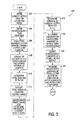
- Figure 3 depicts a flow chart showing an exemplary method 300 for dynamically estimating output variances for a smoothing filter, which can be used, for example, with filter 200 shown in Figure 2 in accordance with a preferred embodiment of the present invention.
- An example of computer code that can be used to implement method 300 in software is incorporated as Appendix I.
- method 300 initializes the smoothing filter, then the variance equation is initialized, and for each input set ( ⁇ ACC , ⁇ ), from navigation system receiver 100, filter 200 is executed and using the new set of the variances of ⁇ , ⁇ ACC from navigation system receiver 100, method 300 iterates the variance equation.
- a variance reaction ratio for filter 200 is 0.005025 for the raw pseudorange input ( ⁇ ) and 0.985025 for the accumulated phase input ( ⁇ ACC ).
- These variance reduction ratio values were obtained using a MATLAB simulation by summing the impulse response of each filter channel used.
- a closed-form solution for the transient variance of smoothing fitter 200 may be derived in terms of the input signal variances and the filter coefficient/sampling interval as the filter settles down (stabilizes) from initialization to steady state.
- the resulting equation for that closed-form solution can be used to validate the values shown above in equation (2).
- S 0 the initial value of the fed-back output term (initialized to ⁇ 0 )
- ⁇ 0 the initial pseudorange value
- ⁇ 0 the initial accumulated phase input value.
- ⁇ S n 2 ⁇ 2 ⁇ ⁇ ⁇ 2 ⁇ k 1 + ⁇ 2 ⁇ ⁇ ⁇ 2 ⁇ k 2 + ⁇ 2 ⁇ n ⁇ ⁇ S 0 2
- equation (10) was originally predicated on the assumption that the variance values are constant over the sample interval
- this assumption is valid for ⁇ ⁇ 2 , but it does not hold up for transients in ⁇ ⁇ 2 because the output of the fitter has forcing inputs from both ⁇ ⁇ n 2 and ⁇ ⁇ n - 1 2
- equation (10) should have an additional term to account for the step change in the carrier noise variance from one sample to the next. Without such a term, the transient response to changes in the carrier variance may not be correct.
- ⁇ S n 2 ⁇ 2 ⁇ ⁇ ⁇ n 2 + 2 ⁇ ⁇ ⁇ ⁇ 2 ⁇ ⁇ ⁇ n - 1 2 + ⁇ 2 ⁇ ⁇ ⁇ S - 1 2 + ⁇ 2 ⁇ ⁇ ⁇ n 2 - ⁇ ⁇ n - 1 2
- equation (11) was thoroughly tested in MATLAB evaluations that produced excellent results across wide variations in filter gain as wen as injected transient values of ⁇ ⁇ 2 and ⁇ ⁇ 2 , As such, the final steady-state variance of the stable filter ( 200 ) can be determined by returning to equation (9) and continuing the derivation by lowing the value of n ⁇ ⁇ .
- ⁇ S n 2 ⁇ 2 ⁇ ⁇ ⁇ 2 [ 1 ⁇ ( 2 - ⁇ ) ] + ⁇ 2 ⁇ ⁇ ⁇ 2 ⁇ 2 ⁇ ⁇ [ 1 ⁇ ( 2 - ⁇ ) ]
- Figure 4 depicts a graph 400 of the results of an example MATLAB simulation, which illustrates a successful application of method 300 for a smoothing filter (e.g. , filter 200), in accordance with a preferred embodiment of the present invention.
- the line designated as 402 shows the actual calculated variance of the output of the filter used, as the code-based pseudorange and carrier-phase variance values are stepped to different values during the filter's operation.
- the line designated as 404 shows the predicted settling point of the output variance of the filter given the set of pseudorange and carrier-phase variance values being applied (e.g. , calculated using equation (12)).
- the line designated as 406 shows the dynamically calculated (predicted) output variance of the filter as it transitions in response to new variance input values (e.g., calculated using equation (11)).
- a novel method for dynamically calculating an output variance for a smoothing filter as it transitions in response to new input variance values.
- the method also predicts the settling point of the output variance for that smoothing filter given a set of pseudorange and carrier-phase values to be applied. Therefore, using the novel output variance prediction method of the present invention, precision navigation applications such as, for example, airborne GPS-based precision landing system applications can begin operations with suitable calculated protection level values without having to wait for the smoothing filters to stabilize. Consequently, such precision landing systems are available for use as soon as the required protection level values are reached.
Landscapes
- Engineering & Computer Science (AREA)
- Radar, Positioning & Navigation (AREA)
- Remote Sensing (AREA)
- Computer Networks & Wireless Communication (AREA)
- Physics & Mathematics (AREA)
- General Physics & Mathematics (AREA)
- Aviation & Aerospace Engineering (AREA)
- Position Fixing By Use Of Radio Waves (AREA)
Abstract
Description
- The present invention relates generally to the field of navigation and guidance systems, and more specifically, but not exclusively, to a system and method for dynamically estimating output variances for carrier-smoothing filters used, for example, in global positioning system-based navigation or guidance systems or similar types of navigation or guidance systems.
- Satellite-based navigation and guidance systems are known. For example, the Global Positioning System (GPS) is a satellite navigation system used for determining one's precise location, by estimating the three-dimensional, global position of a radio receiver. The receiver, which can be hand-held or mounted to a vehicle such as an aircraft receives coded signals from a number of earth-orbifing satellite transmitters. Each received signal indicates the position of its satellite transmitter and its transmission time, which enables the receiver (using an internal clock) to approximate signal transit times and estimate the distances to the transmitters. These distances are referred to as "pseudoranges." In practice, a processor associated with the receiver uses at least four of these pseudoranges to estimate the position (e.g., latitude, longitude and altitude) of the receiver and the associated vehicle with a technique known as trilateration. The accuracy of these position solutions depends on certain factors such as, for example, atmospheric conditions and the performance of the individual satellite transmitters. A satellite navigation system similar to the GPS is the Russian-operated Global Navigation Satellite System (GLONASS).
- In recent years, the GPS has been extended for use with aircraft during the more critical portions of a flight (e.g., landings). These satellite-based precision landing systems are ground-augmented, differential systems that typically include two-to-four ground-based GPS receivers, a ground-based differential correction processor (DCP), and a correction-data transmitter. These components are located near the aircraft landing areas involved. The ground-based GPS receivers determine sets of pseudoranges based on signals received from at least four satellite transmitters. These pseudorange measurements are forwarded to the ground-based DCP, which uses the pseudoranges and known positions of the ground receivers to produce an error correction factor, The correction-data transmitter transmits the error correction factor to approaching aircraft, which use this correction data to increase the accuracy of the position estimates provided by onboard GPS receivers. A civilian version of such a satellite-based precision landing system is the GPS-based Local Area Augmentation System (LAAS), and a military version is the Joint Precision Approach and Landing System (JPALS).
- Essentially, GPS receivers perform two types of measurements. One such measurement is code-based, whereby the receiver tracks the code modulation of the GPS signal to determine the pseudorange. The other measurement is carrier-based, whereby the receiver tracks the carrier phase of the GPS signal. Notably, phase measurements of the carrier signal typically have much less noise than code-based measurements. Consequently, a carrier phase smoothing process has been developed for use in GPS receivers, which combines the code-based pseudorange measurements with the integral of the carrier phase measurements in order to mitigate the noise inherent in the code-based pseudorange tracking process. Essentially, carrier-smoothing is used in GPS receivers for certain precision applications (e.g., LAAS, JPALS, etc.) in order to eliminate as much high frequency noise as possible from the pseudorange measurements involved.
- GPS receivers track the code-modulated signals using delay lock loops (DLLs), and the carrier phase signals are tracked with phase lock loops (PLLs). Carrier-smoothing of the code-based pseudorange measurements is typically performed by coupling data from the carrier phase tracking loops to the code-based tracking portion of the system. Typically, each pseudorange value from the receiver is smoothed with its own smoothing filter. Notably, the Hatch filter is a known smoothing filter that is used in GPS receivers for smoothing code-based pseudorange measurements with continuous carrier phase data.
- A significant problem with existing carrier-smoothing filters used in airborne GPS-based precision landing systems (e.g., LAAS, JPALS, etc.) and similar precision applications is that the filters can take up to 5 minutes to stabilize. Consequently, carrier-smoothing of the code-based pseudorange measurements in existing GPS receivers is not available for precision applications until after the smoothing filters stabilize. Thus, for precision position determination applications, the existing GPS receivers are performance limited and essentially unavailable for use for a significant period of time after the smoothing filters are initialized. Note that the period of unavailability is associated with the time constant of the smoothing filter. This association drives designers to use shorter time constants, which degrades the smoothing. Consequently, there is a need for a technique that allows the use of potentially longer time constants without meaningfully degrading availability. Therefore, given the substantive, continuing need to improve the precision and performance of airborne landing systems and similar precision position determination applications, it would be advantageous to provide a system and method that enables an airborne GPS-based precision landing system or similar precision application to begin operating with appropriate performance parameters without having to wait for the carrier-smoothing filters in the GPS receivers to stabilize. As described in detail below, the present invention provides such a system and method.
- The present invention provides an improved system and method for dynamically estimating the output variances of carrier-smoothing filters used, for example, in GPS receivers. By accurately estimating the output variances of the carrier-smoothing filters as they transition from initialization to steady-state operation, it is possible to calculate any required protection levels without having to wait for the filters to fully stabilize. In accordance with a preferred embodiment of the present invention, a system for estimating output variances of a carrier-smoothing filter for use in a satellite navigation system receiver is provided, which includes a plurality of smoothing filters associated with a navigation processing unit in a satellite navigation receiver. One or more processors associated with the navigation processing unit executes an algorithm for each smoothing filter, which provides a method for dynamically calculating an output variance for a respective smoothing filter as it transitions in response to new input variance values. The method also predicts the settling point of the output variance for that smoothing filter given a set of pseudorange and carrier-phase values to be applied. Therefore, using the novel output variance prediction method of the present invention, precision navigation applications such as, for example, airborne GPS-based precision landing system applications can begin operations with suitable calculated protection level values without having to wait for the smoothing filters to stabilize. Thus, in accordance with the present invention, such precision landing systems are available for use as soon as the required protection level values are reached.
- The novel features believed characteristic of the invention are set forth in the appended claims. The invention itself, however, as well as a preferred mode of use, further objectives and advantages thereof, will best be understood by reference to the following detailed description of an illustrative embodiment when read in conjunction with the accompanying drawings, wherein:
- Figure 1 depicts a simplified block diagram of an example satellite navigation system receiver, which can be used to implement a preferred embodiment of the present invention;
- Figure 2 depicts a simplified block diagram of an example smoothing filter, which can be used to implement a preferred embodiment of the present invention;
- Figure 3 depicts a flow chart showing an exemplary method for dynamically estimating output variances for a smoothing filter, in accordance with a preferred embodiment of the present invention; and
- Figure 4 depicts a graph of the results of an example MATLAB simulation, which illustrates a successful application of the method described with respect to Figure 3, in accordance with a preferred embodiment of the present invention.
- With reference now to the figures, Figure 1 depicts a simplified block diagram of an example satellite
navigation system receiver 100, which can be used to implement a preferred embodiment of the present invention. For example, in one embodiment,receiver 100 can be a GPS receiver for a GPS-based LAAS or JPALS. In another embodiment,receiver 100 can be an embedded 5-channel receiver for an Embedded GPS/Inertial Navigation System (BGI) such as, for example, an H-764 Advanced Configurable EGI (ACE) produced by Honeywell International Inc. In any event, it should be understood that the present invention is not intended to be limited only to GPS receiver applications, and can include within its scope any suitable application where a smoothing filter is used to eliminate high frequency noise. - For this example embodiment,
receiver 100 includes a passive band-pass pre-filter andpreamplifier unit 102, which filters and preamplifies the Radio Frequency (RF) signals received from a plurality of satellite transmitters. The preamplified RF signals are coupled to a down-converter and analog-to-digital (A/D)conversion unit 104, which converts the RF signals to an Intermediate Frequency (IF) and then converts these analog signals to digital form. Typically, these digital signals are coupled to a Digital Signal Processor (DSP) 106, which performs suitable digital signal processing to enhance the digital data received. For this example embodiment, the digital data is coupled from DSP 106 to anavigation processing unit 108, which executes suitable algorithms (e.g., implemented in software) to generate position, velocity and time information. As such, one or more microprocessors 110 (e.g., implemented with one or more Power PC-based microprocessors) can be used in association withnavigation processing unit 108 and/or DSP 106, in order to execute suitable algorithms (e.g., implemented in software) that perform carrier phase smoothing of the code-based pseudorange measurement data generated inreceiver 100, and dynamically estimates the output variances of carrier-smoothing filters used, in accordance with teachings of the present invention. - Figure 2 depicts a simplified block diagram of an
example smoothing filter 200, which can be used to implement a preferred embodiment of the present invention. For example,smoothing filter 200 can represent one filter of a plurality of Hatch-type smoothing filters that can be used for carrier phased smoothing of a plurality of code-based pseudorange signals (e.g., fromreceiver 100 in Figure 1). Essentially, for this example embodiment, using dual-frequency carrier phases (e.g., L1 and L2), each available pseudorange value received (e.g., from receiver 100) can be smoothed with arespective smoothing filter 200. Thus, for this example,smoothing filter 200 accepts two inputs: the accumulated carrier phase value (φACC ); and a new code-based pseudorange value (ρ). For each input code-based pseudorange value (ρ),smoothing filter 200 produces at its output a new, smoothed pseudorange value (ρsmooth) by combining a projected pseudorange value based on the accumulated phase data, with the current code-based pseudorange value. - For this example embodiment,
smoothing filter 200 is implemented as an algorithm (e.g., software executed bymicroprocessor 110 in Figure 1), which includes two one-sample delays adders amplifiers - Figure 3 depicts a flow chart showing an
exemplary method 300 for dynamically estimating output variances for a smoothing filter, which can be used, for example, withfilter 200 shown in Figure 2 in accordance with a preferred embodiment of the present invention. An example of computer code that can be used to implementmethod 300 in software is incorporated as Appendix I. Essentially, in accordance with the present invention,method 300 initializes the smoothing filter, then the variance equation is initialized, and for each input set (φACC,ρ), fromnavigation system receiver 100,filter 200 is executed and using the new set of the variances of ρ, φACC fromnavigation system receiver 100,method 300 iterates the variance equation. - Specifically, referring now to Figures 2 and 3, for this example embodiment, the filter gain (α) value for smoothing
filter 200 is defined as:
where ts is the sample interval, and 100 seconds is a predetermined, fixed time constant value. Thus, assuming that a sampling interval intofilter 200 is 1.0 second, a variance reaction ratio forfilter 200 is 0.005025 for the raw pseudorange input (ρ) and 0.985025 for the accumulated phase input (φ ACC ). These variance reduction ratio values were obtained using a MATLAB simulation by summing the impulse response of each filter channel used. Thus, the steady-state variance forfilter 200 may be represented as:
- For this example embodiment, a closed-form solution for the transient variance of smoothing fitter 200 may be derived in terms of the input signal variances and the filter coefficient/sampling interval as the filter settles down (stabilizes) from initialization to steady state. The resulting equation for that closed-form solution can be used to validate the values shown above in equation (2). As such, at
step 302 of the method, filter 200 may be represented as:
step 304, the output terms S n-1,S n-2; may be defined as:
- At
step 306, these terms are then substituted into the filter equation (3):
- At
step 308, by inspection, equation (5) can be generalized for a sample interval of n=0 to N:


step 310, a generalized equation for the total variance of the filter is:


- At this point, the total variance equation (7) can be simplified by recognizing that the power series terms may be expressed as closed forms (at step 312):

- The two power series terms can then be reduced to standard forms:

- By substitution, the value of k 1 has a dosed solution of


step 314, substituting this new term for k 2 into equation (8) above produces:
- The incremental expression for the variance


step 316, equation (9) becomes:
- As such, the derivation of this equation (10) was originally predicated on the assumption that the variance values are constant over the sample interval However, in practicality, this assumption is valid for


- Thus, at
step 318, the final equation to be used for calculating

- Notably, equation (11) was thoroughly tested in MATLAB evaluations that produced excellent results across wide variations in filter gain as wen as injected transient values of


step 320, as n → ∞, the initial feedback variance term,

- Consequently, reducing equation (12) slightly, at
step 322, the steady-state variance of the output of the smoothingfilter 200, defined as a function of the input variances and the filter gain coefficient, becomes:
- Figure 4 depicts a
graph 400 of the results of an example MATLAB simulation, which illustrates a successful application ofmethod 300 for a smoothing filter (e.g., filter 200), in accordance with a preferred embodiment of the present invention. As such, for this illustrative example, the line designated as 402 shows the actual calculated variance of the output of the filter used, as the code-based pseudorange and carrier-phase variance values are stepped to different values during the filter's operation. The line designated as 404 shows the predicted settling point of the output variance of the filter given the set of pseudorange and carrier-phase variance values being applied (e.g., calculated using equation (12)). The line designated as 406 shows the dynamically calculated (predicted) output variance of the filter as it transitions in response to new variance input values (e.g., calculated using equation (11)). - As such, in accordance with a preferred embodiment of the present invention, a novel method is provided for dynamically calculating an output variance for a smoothing filter as it transitions in response to new input variance values. The method also predicts the settling point of the output variance for that smoothing filter given a set of pseudorange and carrier-phase values to be applied. Therefore, using the novel output variance prediction method of the present invention, precision navigation applications such as, for example, airborne GPS-based precision landing system applications can begin operations with suitable calculated protection level values without having to wait for the smoothing filters to stabilize. Consequently, such precision landing systems are available for use as soon as the required protection level values are reached.
- It is important to note that while the present invention has been described in the context of a fully functioning navigation system, those of ordinary skill in the art will appreciate that the processes of the present invention are capable of being distributed in the form of a computer readable medium of instructions and a variety of forms and that the present invention applies equally regardless of the particular type of signal bearing media actually used to Carry out the distribution. Examples of computer readable media include recordable-type media, such as a floppy disk, a hard disk drive, a RAM, CD-ROMs, DVD-ROMs, and transmission-type media, such as digital and analog communications links, wired or wireless communications links using transmission forms, such as, for example, radio frequency and light wave transmissions. The computer readable media may take the form of coded formats that are decoded for actual use in a particular navigation system.
- The description of the present invention has been presented for purposes of illustration and description, and is not intended to be exhaustive or limited to the invention in the form disclosed. Many modifications and variations will be apparent to those of ordinary skill in the art. These embodiments were chosen and described in order to best explain the principles of the invention, the practical application, and to enable others of ordinary skill in the art to understand the invention for various embodiments with various Modifications as are suited to the particular use contemplated.
Claims (10)
- A method (300) for dynamically estimating output variances for a smoothing filter, comprising the steps of:defining a current output term for the smoothing filter (302);determining a total variance term for the smoothing filter (310);determining a variance of said current output term (316); andredefining said variance of said current output term in an incremental form (322).
- The method (300) of Claim 1, further comprising the steps of:deriving a steady-state variance of said smoothing filter (320); andredefining said steady-state variance as a function of at least one of a plurality of input variances and a gain coefficient (322).
- The method (300) of Claim 1, further comprising the steps of:redefining said current output term with a plurality of previous output terms (306); andgeneralizing said redefined current output term, by defining said current output term for a sample interval of n = 0 to N (308).
- The method (300) of Claim 2, whereby said steady-state variance of said smoothing filter defined as a function of a plurality of input variances and a filter gain coefficient is expressed as

- The method (300) of Claim 1, wherein said smoothing filter (200) comprises a Hatch filter.
- The method (300) of Claim 1, wherein said smoothing filter (200) comprises a pseudorange smoothing filter for use with a satellite navigation receiver system (100).
- The method (300) of Claim 1, wherein said smoothing filter (200) comprises a carrier-phase smoothing filter.
- The method (300) of Claim 1, wherein said smoothing filter (200) comprises a carrier-phase smoothing filter far a plurality of pseudoranges.
- The method (300) of Claim 1, wherein an input of said smoothing filter (200) comprises at least one of an accumulated carrier phase value and a pseudorange value.
- The method (300) of Claim 1, wherein an output of said smoothing filter (200) is represented as a steady-state variance of said smoothing filter (200).
Applications Claiming Priority (1)
| Application Number | Priority Date | Filing Date | Title |
|---|---|---|---|
| US11/215,169 US7609204B2 (en) | 2005-08-30 | 2005-08-30 | System and method for dynamically estimating output variances for carrier-smoothing filters |
Publications (2)
| Publication Number | Publication Date |
|---|---|
| EP1760484A2 true EP1760484A2 (en) | 2007-03-07 |
| EP1760484A3 EP1760484A3 (en) | 2008-06-25 |
Family
ID=37507440
Family Applications (1)
| Application Number | Title | Priority Date | Filing Date |
|---|---|---|---|
| EP06119782A Withdrawn EP1760484A3 (en) | 2005-08-30 | 2006-08-30 | System and method for dynamically estimating output variances for carrier-smoothing filters |
Country Status (3)
| Country | Link |
|---|---|
| US (1) | US7609204B2 (en) |
| EP (1) | EP1760484A3 (en) |
| CA (1) | CA2557684A1 (en) |
Families Citing this family (4)
| Publication number | Priority date | Publication date | Assignee | Title |
|---|---|---|---|---|
| US7570204B1 (en) * | 2006-08-31 | 2009-08-04 | Rockwell Collins, Inc. | Generalized divergence-free carrier smoothing and dual frequency differential GPS architecture implementing the same |
| FR2939901B1 (en) * | 2008-12-17 | 2011-02-18 | Sagem Defense Securite | KALMAN SEGREGES FILTER HYBRIDIZATION DEVICE |
| US9158000B2 (en) | 2012-06-12 | 2015-10-13 | Honeywell International Inc. | Enhanced location based services |
| US8976064B2 (en) | 2012-09-06 | 2015-03-10 | Honeywell International Inc. | Systems and methods for solution separation for ground-augmented multi-constellation terminal area navigation and precision approach guidance |
Family Cites Families (63)
| Publication number | Priority date | Publication date | Assignee | Title |
|---|---|---|---|---|
| US694791A (en) * | 1900-02-17 | 1902-03-04 | Richard E Sack | Steering-gear. |
| US1057583A (en) * | 1912-05-27 | 1913-04-01 | Cleveland H Schenk | Drafting and scaling instrument. |
| US1554751A (en) * | 1923-09-07 | 1925-09-22 | G & G Atlas Systems Inc | Cash carrier |
| US2208631A (en) * | 1937-12-20 | 1940-07-23 | Chrysler Corp | Injection engine |
| US2211041A (en) * | 1938-04-13 | 1940-08-13 | Pennsylvania Patents Inc | Tuning control device for radio receiviers and the like |
| US3137459A (en) * | 1960-07-14 | 1964-06-16 | Martin Marietta Corp | Closed loop servo control system |
| DE1284852B (en) | 1962-12-11 | 1968-12-05 | Teldix Luftfahrt Ausruestung | Landing system for aircraft landing vertically or at a steep angle |
| US3603994A (en) | 1966-04-26 | 1971-09-07 | Hughes Aircraft Co | System for automatically generating smoothing parameters in an automatic track-while-scan radar system |
| US3975731A (en) | 1974-12-10 | 1976-08-17 | Grumman Aerospace Corporation | Airborne positioning system |
| US4030686A (en) | 1975-09-04 | 1977-06-21 | Hughes Aircraft Company | Position determining systems |
| US4578678A (en) * | 1983-11-14 | 1986-03-25 | The United States Of America As Represented By The United States National Aeronautics And Space Administration | High dynamic global positioning system receiver |
| US4737794A (en) | 1985-12-09 | 1988-04-12 | Mcdonnell Douglas Corporation | Method and apparatus for determining remote object orientation and position |
| US4807256A (en) * | 1985-12-23 | 1989-02-21 | Texas Instruments Incorporated | Global position system receiver |
| IL87382A (en) | 1987-08-13 | 1994-07-31 | Grumman Aerospace Corp | Aircraft precision landing approach system |
| JPH0198100A (en) | 1987-10-09 | 1989-04-17 | Japan Radio Co Ltd | Mls receiver |
| US5018218A (en) * | 1988-08-29 | 1991-05-21 | Raytheon Company | Confirmed boundary pattern matching |
| AU639308B2 (en) | 1990-03-09 | 1993-07-22 | Sigtec Navigation Pty Ltd | G p s receiver |
| US5323322A (en) | 1992-03-05 | 1994-06-21 | Trimble Navigation Limited | Networked differential GPS system |
| US5740048A (en) * | 1992-08-07 | 1998-04-14 | Abel; Jonathan S. | Method and apparatus for GPS positioning, filtering and integration |
| US5296861A (en) | 1992-11-13 | 1994-03-22 | Trimble Navigation Limited | Method and apparatus for maximum likelihood estimation direct integer search in differential carrier phase attitude determination systems |
| US5343212A (en) | 1992-12-11 | 1994-08-30 | Litton Industries, Inc. | (AOA/LBI) emitter ranging method and apparatus |
| US5471217A (en) * | 1993-02-01 | 1995-11-28 | Magnavox Electronic Systems Company | Method and apparatus for smoothing code measurements in a global positioning system receiver |
| US5450448A (en) | 1993-04-30 | 1995-09-12 | Trimble Navigation Limited | Removal of signal errors for differential satellite positioning systems |
| US5563917A (en) * | 1993-04-30 | 1996-10-08 | Trimble Navigation Limited | Compensation for multipath errors and ionospheric delays in differential satellite positioning systems |
| US5796773A (en) * | 1994-03-22 | 1998-08-18 | Trimble Navigation Limited | Compensating for multipath errors, ionospheric time delay and noise errors in differential satellite positioning systems |
| US5831575A (en) | 1994-04-12 | 1998-11-03 | Nfs-Navigations- Und Flugfuehrungs-Systeme Gmbh | Satellite navigation method |
| US6865477B2 (en) | 1994-05-31 | 2005-03-08 | Winged Systems Corporation | High resolution autonomous precision positioning system |
| US5451964A (en) | 1994-07-29 | 1995-09-19 | Del Norte Technology, Inc. | Method and system for resolving double difference GPS carrier phase integer ambiguity utilizing decentralized Kalman filters |
| US5594453A (en) | 1994-11-01 | 1997-01-14 | Trimble Navigation, Ltd | GPS receiver having a rapid acquisition of GPS satellite signals |
| BR9502171A (en) | 1995-05-31 | 1997-08-26 | Dynapac Equipamentos Ind Ltda | Ballast system for compaction machine |
| US5774829A (en) | 1995-12-12 | 1998-06-30 | Pinterra Corporation | Navigation and positioning system and method using uncoordinated beacon signals in conjunction with an absolute positioning system |
| US5828336A (en) | 1996-03-29 | 1998-10-27 | The United States Of America As Represented By The Administrator Of The National Aeronautics And Space Administration | Robust real-time wide-area differential GPS navigation |
| US5751777A (en) * | 1996-05-03 | 1998-05-12 | Symmetricom, Inc. | Multiple input frequency locked loop |
| FR2749668B1 (en) * | 1996-06-07 | 1998-08-28 | Sextant Avionique | SATELLITE SIGNAL RECEIVER WITH POSITION EXTRAPOLATION FILTER |
| US5774387A (en) * | 1996-06-12 | 1998-06-30 | Texas Instruments Incorporated | Tracking filter |
| US5825326A (en) | 1996-07-09 | 1998-10-20 | Interstate Electronics Corporation | Real-time high-accuracy determination of integer ambiguities in a kinematic GPS receiver |
| US5937349A (en) * | 1996-10-29 | 1999-08-10 | Motorola, Inc. | Method and system of tracking dynamic communication parameters during a link interruption |
| US6345232B1 (en) * | 1997-04-10 | 2002-02-05 | Urban H. D. Lynch | Determining aircraft position and attitude using GPS position data |
| US5883595A (en) * | 1997-09-15 | 1999-03-16 | Rockwell International Corporation | Method and apparatus for mitigating multipath effects and smoothing groundtracks in a GPS receiver |
| US6234799B1 (en) | 1998-04-06 | 2001-05-22 | American Gnc Corporation | Real-time IMU simulator |
| US6052082A (en) | 1998-05-14 | 2000-04-18 | Wisconsin Alumni Research Foundation | Method for determining a value for the phase integer ambiguity and a computerized device and system using such a method |
| US6204808B1 (en) | 1998-08-13 | 2001-03-20 | Ericsson Inc. | Method and system for aiding GPS receivers via a cellular or PCS network |
| US6163754A (en) * | 1998-11-25 | 2000-12-19 | Trimble Navigation Limited | Compensation for line bias variation |
| US6198430B1 (en) * | 1999-03-26 | 2001-03-06 | Rockwell Collins, Inc. | Enhanced differential GNSS carrier-smoothed code processing using dual frequency measurements |
| US6266009B1 (en) * | 1999-03-26 | 2001-07-24 | Rockwell Collins, Inc. | Method to improve carrier smoothing of code pseudorange for global positioning and GNSS receiver implementing the same |
| US6311127B1 (en) * | 1999-09-02 | 2001-10-30 | Rockwell Collins | Satellite navigation system having redundant signal processing and matched filtering |
| US6760663B2 (en) * | 1999-09-14 | 2004-07-06 | Honeywell International Inc. | Solution separation method and apparatus for ground-augmented global positioning system |
| CA2381314A1 (en) * | 1999-12-30 | 2001-07-12 | Bandspeed, Inc. | Approach for processing data received from a communications channel in finite precision arithmetic applications |
| US6778136B2 (en) | 2001-12-13 | 2004-08-17 | Sirf Technology, Inc. | Fast acquisition of GPS signal |
| US6329946B1 (en) | 2000-05-31 | 2001-12-11 | Mitsubishi Denki Kabushiki Kaisha | GPS position measuring system and GPS position measuring apparatus |
| US6417801B1 (en) * | 2000-11-17 | 2002-07-09 | Global Locate, Inc. | Method and apparatus for time-free processing of GPS signals |
| JP3958069B2 (en) * | 2001-03-28 | 2007-08-15 | 株式会社東芝 | Radiation measurement equipment |
| US6944540B2 (en) | 2002-03-28 | 2005-09-13 | Motorola, Inc. | Time determination in satellite positioning system receivers and methods therefor |
| US6832155B2 (en) * | 2002-09-23 | 2004-12-14 | Itt Manufacturing Enterprises, Inc. | Methods and apparatus for determining phase ambiguities in ranging and navigation systems |
| US6885917B2 (en) | 2002-11-07 | 2005-04-26 | The Boeing Company | Enhanced flight control systems and methods for a jet powered tri-mode aircraft |
| US6781542B2 (en) * | 2003-01-13 | 2004-08-24 | The Boeing Company | Method and system for estimating ionospheric delay using a single frequency or dual frequency GPS signal |
| US6856905B2 (en) * | 2003-04-29 | 2005-02-15 | Garmin At, Inc. | Systems and methods for fault detection and exclusion in navigational systems |
| US7117417B2 (en) * | 2003-07-30 | 2006-10-03 | Navcom Technology, Inc. | Method for generating clock corrections for a wide-area or global differential GPS system |
| US20060047413A1 (en) * | 2003-12-02 | 2006-03-02 | Lopez Nestor Z | GNSS navigation solution integrity in non-controlled environments |
| US7437013B2 (en) * | 2003-12-23 | 2008-10-14 | General Instrument Corporation | Directional spatial video noise reduction |
| US20050203702A1 (en) * | 2004-03-12 | 2005-09-15 | Sharpe Richard T. | Method for backup dual-frequency navigation during brief periods when measurement data is unavailable on one of two frequencies |
| US20050212696A1 (en) * | 2004-03-25 | 2005-09-29 | Bartone Chris G | Reat-time WaveSmooth™ error mitigation for Global Navigation Satellite Systems |
| US7151405B2 (en) * | 2004-07-14 | 2006-12-19 | Raytheon Company | Estimating power amplifier non-linearity in accordance with memory depth |
-
2005
- 2005-08-30 US US11/215,169 patent/US7609204B2/en not_active Expired - Fee Related
-
2006
- 2006-08-29 CA CA002557684A patent/CA2557684A1/en not_active Abandoned
- 2006-08-30 EP EP06119782A patent/EP1760484A3/en not_active Withdrawn
Non-Patent Citations (2)
| Title |
|---|
| ENGE P: "Local Area Augmentation of GPS for the Precision Approach of Aircraft" PROC IEEE, VOL 87, NO 1, vol. 87, no. 1, 1 January 1999 (1999-01-01), XP011044139 ISSN: 0018-9219 * |
| SWIDER R ET AL: "Recent developments in the LAAS program GPS" POSITION LOCATION AND NAVIGATION SYMPOSIUM, IEEE 1998 PALM SPRINGS, CA, USA 20-23 APRIL 1998, NEW YORK, NY, USA,IEEE, US, 20 April 1998 (1998-04-20), pages 441-470, XP010276866 ISBN: 978-0-7803-4330-6 * |
Also Published As
| Publication number | Publication date |
|---|---|
| EP1760484A3 (en) | 2008-06-25 |
| CA2557684A1 (en) | 2007-02-28 |
| US20070046535A1 (en) | 2007-03-01 |
| US7609204B2 (en) | 2009-10-27 |
Similar Documents
| Publication | Publication Date | Title |
|---|---|---|
| US9341719B2 (en) | Psuedo maximum likelihood tracking for global navigation satellite systems | |
| US6198430B1 (en) | Enhanced differential GNSS carrier-smoothed code processing using dual frequency measurements | |
| US9798017B2 (en) | Reducing time and increasing reliability of ambiguity resolution in GNSS | |
| CN100399047C (en) | Method and apparatus for estimating speed of terminal in wireless communication system | |
| EP2356482B1 (en) | Mobile unit's position measurement apparatus and mobile unit's position measurement method | |
| US11906635B2 (en) | Method and system for recreating unavailable GNSS measurements | |
| US20050024263A1 (en) | Method for generating clock corrections for a wide-area or global differential GPS system | |
| EP2864809B9 (en) | Selection of a subset of global navigation satellite system measurements based on prediction of accuracy of target parameters | |
| US6771215B2 (en) | Determination of the transmission time of a signal part in a positioning system | |
| JP2001183439A (en) | General-purpose positioning system based on use of statistical filter | |
| US7567208B2 (en) | Position and time determination under weak signal conditions | |
| US20050203702A1 (en) | Method for backup dual-frequency navigation during brief periods when measurement data is unavailable on one of two frequencies | |
| US20070115171A1 (en) | Methods and apparatus to detect and correct integrity failures in satellite positioning system receivers | |
| EP0704063A1 (en) | Satellite positioning system filter | |
| US6266009B1 (en) | Method to improve carrier smoothing of code pseudorange for global positioning and GNSS receiver implementing the same | |
| US20100309043A1 (en) | Method for determining the distance between a transmitter and a receiver | |
| JP2006189320A (en) | Positioning calculator, positioning device, and positioning calculation method | |
| US7903028B2 (en) | Ephemeris download from weak signals | |
| US7609204B2 (en) | System and method for dynamically estimating output variances for carrier-smoothing filters | |
| US6297769B1 (en) | System and method to estimate carrier signal in global positioning systems (GPS) | |
| EP1229341B1 (en) | A method for defining the error of reference time and an electronic device | |
| US20040189518A1 (en) | Signal deformation monitor | |
| JP3749850B2 (en) | GPS receiver that outputs 2DRMS using URA, 2DRMS calculation method, and car navigation system | |
| JP3544887B2 (en) | GPS receiving device and GPS receiving method applied to this device | |
| Vani et al. | Evaluation of GPS data for navigational solution and error reduction using kalman filter |
Legal Events
| Date | Code | Title | Description |
|---|---|---|---|
| PUAI | Public reference made under article 153(3) epc to a published international application that has entered the european phase |
Free format text: ORIGINAL CODE: 0009012 |
|
| AK | Designated contracting states |
Kind code of ref document: A2 Designated state(s): AT BE BG CH CY CZ DE DK EE ES FI FR GB GR HU IE IS IT LI LT LU LV MC NL PL PT RO SE SI SK TR |
|
| AX | Request for extension of the european patent |
Extension state: AL BA HR MK YU |
|
| PUAL | Search report despatched |
Free format text: ORIGINAL CODE: 0009013 |
|
| AK | Designated contracting states |
Kind code of ref document: A3 Designated state(s): AT BE BG CH CY CZ DE DK EE ES FI FR GB GR HU IE IS IT LI LT LU LV MC NL PL PT RO SE SI SK TR |
|
| AX | Request for extension of the european patent |
Extension state: AL BA HR MK RS |
|
| 17P | Request for examination filed |
Effective date: 20081211 |
|
| 17Q | First examination report despatched |
Effective date: 20090113 |
|
| AKX | Designation fees paid |
Designated state(s): FR GB |
|
| REG | Reference to a national code |
Ref country code: DE Ref legal event code: 8566 |
|
| STAA | Information on the status of an ep patent application or granted ep patent |
Free format text: STATUS: THE APPLICATION IS DEEMED TO BE WITHDRAWN |
|
| 18D | Application deemed to be withdrawn |
Effective date: 20110301 |