EP1760391A2 - Light emitting diode lamp - Google Patents
Light emitting diode lamp Download PDFInfo
- Publication number
- EP1760391A2 EP1760391A2 EP06016363A EP06016363A EP1760391A2 EP 1760391 A2 EP1760391 A2 EP 1760391A2 EP 06016363 A EP06016363 A EP 06016363A EP 06016363 A EP06016363 A EP 06016363A EP 1760391 A2 EP1760391 A2 EP 1760391A2
- Authority
- EP
- European Patent Office
- Prior art keywords
- light emitting
- emitting diode
- electrical connectors
- electrically conductive
- conductive plate
- Prior art date
- Legal status (The legal status is an assumption and is not a legal conclusion. Google has not performed a legal analysis and makes no representation as to the accuracy of the status listed.)
- Withdrawn
Links
Images

Classifications
-
- F—MECHANICAL ENGINEERING; LIGHTING; HEATING; WEAPONS; BLASTING
- F21—LIGHTING
- F21K—NON-ELECTRIC LIGHT SOURCES USING LUMINESCENCE; LIGHT SOURCES USING ELECTROCHEMILUMINESCENCE; LIGHT SOURCES USING CHARGES OF COMBUSTIBLE MATERIAL; LIGHT SOURCES USING SEMICONDUCTOR DEVICES AS LIGHT-GENERATING ELEMENTS; LIGHT SOURCES NOT OTHERWISE PROVIDED FOR
- F21K9/00—Light sources using semiconductor devices as light-generating elements, e.g. using light-emitting diodes [LED] or lasers
- F21K9/20—Light sources comprising attachment means
- F21K9/23—Retrofit light sources for lighting devices with a single fitting for each light source, e.g. for substitution of incandescent lamps with bayonet or threaded fittings
-
- F—MECHANICAL ENGINEERING; LIGHTING; HEATING; WEAPONS; BLASTING
- F21—LIGHTING
- F21S—NON-PORTABLE LIGHTING DEVICES; SYSTEMS THEREOF; VEHICLE LIGHTING DEVICES SPECIALLY ADAPTED FOR VEHICLE EXTERIORS
- F21S41/00—Illuminating devices specially adapted for vehicle exteriors, e.g. headlamps
- F21S41/10—Illuminating devices specially adapted for vehicle exteriors, e.g. headlamps characterised by the light source
- F21S41/19—Attachment of light sources or lamp holders
-
- F—MECHANICAL ENGINEERING; LIGHTING; HEATING; WEAPONS; BLASTING
- F21—LIGHTING
- F21Y—INDEXING SCHEME ASSOCIATED WITH SUBCLASSES F21K, F21L, F21S and F21V, RELATING TO THE FORM OR THE KIND OF THE LIGHT SOURCES OR OF THE COLOUR OF THE LIGHT EMITTED
- F21Y2115/00—Light-generating elements of semiconductor light sources
- F21Y2115/10—Light-emitting diodes [LED]
Definitions
- This invention relates to light bulbs and more particularly to solid-state light emitting devices such as light emitting diodes. Still more particularly, it relates light emitting diode bulbs having applicability as light sources for motor vehicle.
- LEDs have enormous life times, in the area of 100,000 hours, and are not as subject to vibration failures.
- these LED sources have been hard-wired into their appropriate location, which increases the cost of installation. It would therefore be an advance in the art if an LED light source could be provided that had the ease of installation of the incandescent light sources. It would be a still further advance in the art if an LED light source could be provided that achieved an industry accepted interchangeable standard to replace the aforementioned incandescent bulb.
- Such light sources have been developed and occasionally they have employed LEDs in combination with optical fibers or other light guides to concentrate the light of multiple LEDs or to spread the light in a desired fashion.
- One such light source is described in co-pending patent application serial no. 10/899,546, filed 12/20/2004 , and assigned to the assignee of the present invention.
- the latter light source uses a plurality of light guides, in a one-to-one relationship with a like plurality of LEDs. While the arrangement works well, it is expensive and requires a large number of parts, all of which require rather precise alignment.
- co-pending patent application S.N As disclosed in co-pending patent application S.N.
- a light emitting diode bulb comprising:
- each of said electrical connectors comprising at least a first electrically conductive plate, a contiguous insulator and a second electrically conductive plate;
- a light emitting diode electrically connected between said at least a first and said second electrically conductive plates adjacent said second end on each of said plurality of electrical connectors.
- Fig. 1 is a plan view of a light emitting diode bulb employing an embodiment of the invention
- Fig. 2 is an elevational view thereof
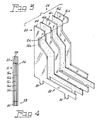
- Fig. 3 is an exploded perspective view of an electrical connector according to an embodiment of the invention.
- Fig. 4 is a front elevational view of an electrical connector according to an embodiment of the invention.
- a light emitting diode bulb 10 comprising a base 12, a printed circuit board 14 contained within said base 12, and a plurality of electrical connectors 16 having a first end 18 mounted upon the printed circuit board 14 and a second end 20 extending away from the base 12 in a direction normal thereto, each of the electrical connectors 16 comprising at least a first electrically conductive plate 16a, a contiguous insulator 16b and a second electrically conductive plate 16c.
- the conductive plates are formed from copper having a thickness of 0.8 mm and the contiguous insulator can be a layer of adhesive 0.25 mm thick.
- other suitable insulator materials or conductive materials can be employed.
- the electrical connector 16 includes an additional insulator 16d and a third electrically conductive plate 16e.
- Such a configuration can be employed for connecting three-lead LEDs such as type Advanced PowerTop (LED), available from Osram Opto, Regensburg, Germany.
- LED type Advanced PowerTop
- a light emitting diode 22 is electrically connected between the conductive plates adjacent the second end 20 on each of the plurality of electrical connectors 16.
- three electrical connectors 16 are arranged 120 degrees apart, as shown most clearly in Fig. 1.
- the first end 18 of the connectors 16 is provided with tabs 30 for engagement with the printed circuit board 14 and for electrical connection to the circuitry thereon.
- the second ends 20 of the electrical connectors 16 comprise an upper, substantially planar surface 24 and an undercut surface 26, with the light emitting diodes 22 being positioned on the undercut surfaces 26.
- the light from the operating LEDs is directed rearwardly, that is, toward the base 12, where, in operation a reflector (not shown) would be positioned. It is then reflected light that is emitted toward the viewing field.
- the electrical connectors 16 provide both the electrical and thermal path for the LEDs as well as positioning the LEDs at an angle for a higher optical efficiency
- the LEDs can be mounted on to the laminated connectors 16 via a reflow process similar to the manner in which surface-mount components are mounted to printed circuit boards. After the LEDs are mounted the driver printed circuit board 14 can be soldered on to the tabs 30 on the first ends 18 of the connectors 16 to form an assembly, which is then overmolded in a suitable plastic, such as Nylon, to provide an electrically insulating layer 31.
- a suitable plastic such as Nylon
- an additional heat sink 32 such as one shown and described in co-pending patent application S.N. 10/838,090, filed 05/03/2004 and assigned to the assignee of the present invention, can be applied.
- the electrically conductive plates and the insulators can be stamped in individual pieces and then laminated or the laminations can be first performed, with the completed connectors subsequently stamped. Changing the distance between the LED and the base can regulate the focal length of the bulb. The number and spacing of the electrical connectors can be changed to accommodate different LEDs.
Landscapes
- Engineering & Computer Science (AREA)
- Physics & Mathematics (AREA)
- Microelectronics & Electronic Packaging (AREA)
- Optics & Photonics (AREA)
- General Engineering & Computer Science (AREA)
- Fastening Of Light Sources Or Lamp Holders (AREA)
- Non-Portable Lighting Devices Or Systems Thereof (AREA)
- Coupling Device And Connection With Printed Circuit (AREA)
Abstract
Description
- This invention relates to light bulbs and more particularly to solid-state light emitting devices such as light emitting diodes. Still more particularly, it relates light emitting diode bulbs having applicability as light sources for motor vehicle.
- In the past, most automotive light sources have involved the use of incandescent bulbs. While working well and being inexpensive, these bulbs have a relatively short life and, of course, the thin filament employed was always subject to breakage due to vibration.
- Recently some of the uses, particularly the stoplight, have been replaced by LEDs. These solid-state light sources have incredible life times, in the area of 100,000 hours, and are not as subject to vibration failures. However, these LED sources have been hard-wired into their appropriate location, which increases the cost of installation. It would therefore be an advance in the art if an LED light source could be provided that had the ease of installation of the incandescent light sources. It would be a still further advance in the art if an LED light source could be provided that achieved an industry accepted interchangeable standard to replace the aforementioned incandescent bulb.
- Such light sources have been developed and occasionally they have employed LEDs in combination with optical fibers or other light guides to concentrate the light of multiple LEDs or to spread the light in a desired fashion. One such light source is described in co-pending patent application serial no.
10/899,546, filed 12/20/2004 11/058,304, filed 02/15/2005 - Accordingly, it would be an advance in the art if an LED bulb could be provided with a simplified construction. It would be a further advance in the art if the diode supporting structures, electrical connectors and heat sinks could be incorporated into a single unit.
- It is, therefore, an object of the invention to obviate the disadvantages of the prior art.
- It is another object of the invention to enhance LED bulbs.
- These objects are accomplished, in one aspect of the invention, by:
- A light emitting diode bulb comprising:
- a base;
- a printed circuit board contained within said base
- a plurality of electrical connectors having a first end mounted upon said printed circuit board and a second end extending away from said base in a direction normal thereto, each of said electrical connectors comprising at least a first electrically conductive plate, a contiguous insulator and a second electrically conductive plate; and
- a light emitting diode electrically connected between said at least a first and said second electrically conductive plates adjacent said second end on each of said plurality of electrical connectors.
- The utilization of the electrical connector as one form of heat sink in addition to functioning as a support for the LEDs greatly simplifies the construction of the bulb.
- Fig. 1 is a plan view of a light emitting diode bulb employing an embodiment of the invention;
- Fig. 2 is an elevational view thereof;
- Fig. 3 is an exploded perspective view of an electrical connector according to an embodiment of the invention; and
- Fig. 4 is a front elevational view of an electrical connector according to an embodiment of the invention.
- For a better understanding of the present invention, together with other and further objects, advantages and capabilities thereof, reference is made to the following disclosure and appended claims taken in conjunction with the above-described drawings.
- Referring now to the drawings with greater particularity, there is shown in Figs. 1 and 2 a light
emitting diode bulb 10 comprising abase 12, a printedcircuit board 14 contained within saidbase 12, and a plurality ofelectrical connectors 16 having afirst end 18 mounted upon the printedcircuit board 14 and asecond end 20 extending away from thebase 12 in a direction normal thereto, each of theelectrical connectors 16 comprising at least a first electricallyconductive plate 16a, a contiguous insulator 16b and a second electricallyconductive plate 16c. Preferably, the conductive plates are formed from copper having a thickness of 0.8 mm and the contiguous insulator can be a layer of adhesive 0.25 mm thick. Alternatively, other suitable insulator materials or conductive materials can be employed. - As shown in Fig. 3, the
electrical connector 16 includes anadditional insulator 16d and a third electricallyconductive plate 16e. Such a configuration can be employed for connecting three-lead LEDs such as type Advanced PowerTop (LED), available from Osram Opto, Regensburg, Germany. - When a two-lead LED is used it is only necessary to use two electrically
conductive plates - A
light emitting diode 22 is electrically connected between the conductive plates adjacent thesecond end 20 on each of the plurality ofelectrical connectors 16. - In a preferred embodiment of the invention, three
electrical connectors 16 are arranged 120 degrees apart, as shown most clearly in Fig. 1. - Preferably, the
first end 18 of theconnectors 16 is provided withtabs 30 for engagement with the printedcircuit board 14 and for electrical connection to the circuitry thereon. - As illustrated, the
second ends 20 of theelectrical connectors 16 comprise an upper, substantiallyplanar surface 24 and anundercut surface 26, with thelight emitting diodes 22 being positioned on theundercut surfaces 26. As thus mounted, the light from the operating LEDs is directed rearwardly, that is, toward thebase 12, where, in operation a reflector (not shown) would be positioned. It is then reflected light that is emitted toward the viewing field. - Thus, the
electrical connectors 16 provide both the electrical and thermal path for the LEDs as well as positioning the LEDs at an angle for a higher optical efficiency, - The LEDs can be mounted on to the laminated
connectors 16 via a reflow process similar to the manner in which surface-mount components are mounted to printed circuit boards. After the LEDs are mounted the driver printedcircuit board 14 can be soldered on to thetabs 30 on thefirst ends 18 of theconnectors 16 to form an assembly, which is then overmolded in a suitable plastic, such as Nylon, to provide an electrically insulatinglayer 31. - After the overmolding process, an
additional heat sink 32, such as one shown and described in co-pending patent application S.N.10/838,090, filed 05/03/2004 - Many variations are possible in the construction of the
LED bulb 10 described above. The electrically conductive plates and the insulators can be stamped in individual pieces and then laminated or the laminations can be first performed, with the completed connectors subsequently stamped. Changing the distance between the LED and the base can regulate the focal length of the bulb. The number and spacing of the electrical connectors can be changed to accommodate different LEDs. - There is thus provided a light emitting diode bulb having a reduced number of parts achieved by combining the electrical and thermal heat sinking functions.
- While there have been shown and described what are present considered to be the preferred embodiments of the invention, it will be apparent to those skilled in the art that various changes and modifications can be made herein without departing from the scope of the invention as defined by the appended claims.
Claims (4)
- A light emitting diode bulb comprising:a base;a printed circuit board contained within said basea plurality of electrical connectors having a first end mounted upon said printed circuit board and a second end extending away from said base in a direction normal thereto, each of said electrical connectors comprising at least a first electrically conductive plate, a contiguous insulator and a second electrically conductive plate; anda light emitting diode electrically connected between said at least a first and said second electrically conductive plates adjacent said second end on each of said plurality of electrical connectors.
- The light emitting diode bulb of Claim 1 wherein each of said electrical connectors comprises a second contiguous insulator and a third electrically conductive plate.
- The light emitting diode bulb of Claim 2 wherein said plurality of electrical connectors comprises 3 such connectors arranged 120 degrees apart.
- The light emitting diode bulb of Claim 3 wherein said second ends of said electrical connectors comprise an upper, substantially planar surface and an undercut surface and said light emitting diodes are positioned on said undercut surfaces.
Applications Claiming Priority (1)
| Application Number | Priority Date | Filing Date | Title |
|---|---|---|---|
| US11/216,294 US20070047251A1 (en) | 2005-08-31 | 2005-08-31 | Light emitting diode bulb |
Publications (2)
| Publication Number | Publication Date |
|---|---|
| EP1760391A2 true EP1760391A2 (en) | 2007-03-07 |
| EP1760391A3 EP1760391A3 (en) | 2008-09-03 |
Family
ID=37116164
Family Applications (1)
| Application Number | Title | Priority Date | Filing Date |
|---|---|---|---|
| EP06016363A Withdrawn EP1760391A3 (en) | 2005-08-31 | 2006-08-04 | Light emitting diode lamp |
Country Status (7)
| Country | Link |
|---|---|
| US (1) | US20070047251A1 (en) |
| EP (1) | EP1760391A3 (en) |
| JP (1) | JP2007066906A (en) |
| KR (1) | KR20070026139A (en) |
| CN (1) | CN1924435A (en) |
| CA (1) | CA2547453A1 (en) |
| TW (1) | TW200732585A (en) |
Cited By (1)
| Publication number | Priority date | Publication date | Assignee | Title |
|---|---|---|---|---|
| WO2021004789A1 (en) | 2019-07-08 | 2021-01-14 | Lumileds Holding B.V. | Support for light-emitting elements and lighting device |
Families Citing this family (7)
| Publication number | Priority date | Publication date | Assignee | Title |
|---|---|---|---|---|
| USD610544S1 (en) * | 2004-04-22 | 2010-02-23 | Osram Sylvania, Inc. | Light emitting diode bulb connector |
| USD586751S1 (en) * | 2004-04-22 | 2009-02-17 | Osram Sylvania, Inc. | Light emitting diode bulb connector |
| USD619964S1 (en) * | 2004-04-22 | 2010-07-20 | Osram Sylvania, Inc. | Light emitting diode bulb connector |
| KR101345350B1 (en) * | 2006-05-23 | 2013-12-30 | 코닌클리케 필립스 엔.브이. | Automotive lamp module and lighting unit with led lighting element |
| US7922364B2 (en) | 2009-03-10 | 2011-04-12 | Osram Sylvania, Inc. | LED lamp assembly |
| USD624233S1 (en) * | 2009-11-27 | 2010-09-21 | Edison Opto Corporation | Lampwick of light emitting diode bulb |
| US9028095B2 (en) * | 2013-09-27 | 2015-05-12 | Wen-Sung Hu | LED bulb with amplifying edge-emitting light structure |
Family Cites Families (7)
| Publication number | Priority date | Publication date | Assignee | Title |
|---|---|---|---|---|
| JP4076329B2 (en) * | 2001-08-13 | 2008-04-16 | エイテックス株式会社 | LED bulb |
| US6525668B1 (en) * | 2001-10-10 | 2003-02-25 | Twr Lighting, Inc. | LED array warning light system |
| US7048412B2 (en) * | 2002-06-10 | 2006-05-23 | Lumileds Lighting U.S., Llc | Axial LED source |
| CN2637885Y (en) * | 2003-02-20 | 2004-09-01 | 高勇 | LED lamp bulb with luminous curved surface |
| US7008095B2 (en) * | 2003-04-10 | 2006-03-07 | Osram Sylvania Inc. | LED lamp with insertable axial wireways and method of making the lamp |
| US6955451B2 (en) * | 2003-08-25 | 2005-10-18 | Osram Sylvania Inc. | Lamp with LED substrates supported by heat conductive post, and method of making such lamp |
| US7086756B2 (en) * | 2004-03-18 | 2006-08-08 | Lighting Science Group Corporation | Lighting element using electronically activated light emitting elements and method of making same |
-
2005
- 2005-08-31 US US11/216,294 patent/US20070047251A1/en not_active Abandoned
-
2006
- 2006-05-23 CA CA002547453A patent/CA2547453A1/en not_active Abandoned
- 2006-08-04 EP EP06016363A patent/EP1760391A3/en not_active Withdrawn
- 2006-08-30 TW TW095131942A patent/TW200732585A/en unknown
- 2006-08-30 KR KR1020060082843A patent/KR20070026139A/en not_active Withdrawn
- 2006-08-30 JP JP2006234432A patent/JP2007066906A/en active Pending
- 2006-08-31 CN CNA2006101422186A patent/CN1924435A/en active Pending
Cited By (3)
| Publication number | Priority date | Publication date | Assignee | Title |
|---|---|---|---|---|
| WO2021004789A1 (en) | 2019-07-08 | 2021-01-14 | Lumileds Holding B.V. | Support for light-emitting elements and lighting device |
| US11274819B2 (en) | 2019-07-08 | 2022-03-15 | Lumileds Llc | Support for light-emitting elements and lighting device |
| US11774080B2 (en) | 2019-07-08 | 2023-10-03 | Lumileds Llc | Support for light-emitting elements and lighting device |
Also Published As
| Publication number | Publication date |
|---|---|
| CN1924435A (en) | 2007-03-07 |
| TW200732585A (en) | 2007-09-01 |
| EP1760391A3 (en) | 2008-09-03 |
| CA2547453A1 (en) | 2007-02-28 |
| JP2007066906A (en) | 2007-03-15 |
| US20070047251A1 (en) | 2007-03-01 |
| KR20070026139A (en) | 2007-03-08 |
Similar Documents
| Publication | Publication Date | Title |
|---|---|---|
| CN105987337B (en) | Light module for a motor vehicle comprising two light guides and a heat sink having two mounting surfaces | |
| US7044620B2 (en) | LED assembly with reverse circuit board | |
| CN1955774B (en) | LED lamp source | |
| KR101398701B1 (en) | Led device, manufacturing method thereof, and light-emitting device | |
| US20090135595A1 (en) | Light bulb with light emitting elements for use in conventional incandescent light bulb sockets | |
| US20140233245A1 (en) | LED-Based Lighting With Reflector Mounted On PCB | |
| JP2006004947A (en) | LED car headlamp | |
| JP2007194172A (en) | Light source module | |
| JP6467753B2 (en) | Light source unit and lighting fixture | |
| JP2012049367A (en) | Semiconductor light-emitting device attachment module, semiconductor light-emitting device module, semiconductor light-emitting device lighting apparatus, and manufacturing method of semiconductor light-emitting device attachment module | |
| CN111059482B (en) | Lighting device with lead frame | |
| EP1684000A2 (en) | Automotive led bulb | |
| EP3527877A1 (en) | Light source unit for lighting tool for vehicle and lighting tool for vehicle | |
| CN1818456B (en) | light emitting diode bulb | |
| US20070047251A1 (en) | Light emitting diode bulb | |
| US7090386B2 (en) | High density LED array | |
| CN104373907A (en) | Attachment and lighting apparatus | |
| KR20140114260A (en) | LED lighting apparatus | |
| JP2011253622A (en) | Light source unit of semiconductor type light source of lighting fixture for vehicle, lighting fixture for vehicle | |
| EP1617135A2 (en) | Molded-in light emitting diode light source | |
| JP7121574B2 (en) | lamp | |
| KR101179172B1 (en) | Fluorescent light type LED illuminator | |
| EP3228923B1 (en) | Light source assembly for vehicle lamp, method for producing light source assembly, signal lamp for automobile vehicle | |
| US10767832B2 (en) | Light source module for vehicle | |
| JP5406540B2 (en) | LIGHT SOURCE MODULE, VEHICLE LIGHT, AND METHOD FOR MANUFACTURING LIGHT SOURCE MODULE |
Legal Events
| Date | Code | Title | Description |
|---|---|---|---|
| PUAI | Public reference made under article 153(3) epc to a published international application that has entered the european phase |
Free format text: ORIGINAL CODE: 0009012 |
|
| AK | Designated contracting states |
Kind code of ref document: A2 Designated state(s): AT BE BG CH CY CZ DE DK EE ES FI FR GB GR HU IE IS IT LI LT LU LV MC NL PL PT RO SE SI SK TR |
|
| AX | Request for extension of the european patent |
Extension state: AL BA HR MK YU |
|
| PUAL | Search report despatched |
Free format text: ORIGINAL CODE: 0009013 |
|
| AK | Designated contracting states |
Kind code of ref document: A3 Designated state(s): AT BE BG CH CY CZ DE DK EE ES FI FR GB GR HU IE IS IT LI LT LU LV MC NL PL PT RO SE SI SK TR |
|
| AX | Request for extension of the european patent |
Extension state: AL BA HR MK RS |
|
| AKX | Designation fees paid | ||
| STAA | Information on the status of an ep patent application or granted ep patent |
Free format text: STATUS: THE APPLICATION IS DEEMED TO BE WITHDRAWN |
|
| 18D | Application deemed to be withdrawn |
Effective date: 20090303 |
|
| REG | Reference to a national code |
Ref country code: DE Ref legal event code: 8566 |