EP1760373A2 - A seal arrangement and a method of seal assembly - Google Patents
A seal arrangement and a method of seal assembly Download PDFInfo
- Publication number
- EP1760373A2 EP1760373A2 EP06254072A EP06254072A EP1760373A2 EP 1760373 A2 EP1760373 A2 EP 1760373A2 EP 06254072 A EP06254072 A EP 06254072A EP 06254072 A EP06254072 A EP 06254072A EP 1760373 A2 EP1760373 A2 EP 1760373A2
- Authority
- EP
- European Patent Office
- Prior art keywords
- seal
- arrangement
- sacrificial material
- gaps
- segments
- Prior art date
- Legal status (The legal status is an assumption and is not a legal conclusion. Google has not performed a legal analysis and makes no representation as to the accuracy of the status listed.)
- Granted
Links
- 238000000034 method Methods 0.000 title claims abstract description 12
- 239000000463 material Substances 0.000 claims abstract description 38
- 238000002844 melting Methods 0.000 claims abstract description 5
- 230000008018 melting Effects 0.000 claims abstract description 5
- 238000007789 sealing Methods 0.000 claims description 16
- 239000002904 solvent Substances 0.000 claims description 8
- 238000010438 heat treatment Methods 0.000 claims description 2
- 230000010339 dilation Effects 0.000 claims 1
- 230000000717 retained effect Effects 0.000 abstract description 4
- 239000001993 wax Substances 0.000 description 12
- 239000012530 fluid Substances 0.000 description 4
- 239000003795 chemical substances by application Substances 0.000 description 2
- 230000001627 detrimental effect Effects 0.000 description 2
- 238000006073 displacement reaction Methods 0.000 description 2
- 230000000694 effects Effects 0.000 description 2
- 230000003068 static effect Effects 0.000 description 2
- 230000006978 adaptation Effects 0.000 description 1
- 238000005516 engineering process Methods 0.000 description 1
- 238000005194 fractionation Methods 0.000 description 1
- 238000011065 in-situ storage Methods 0.000 description 1
- 238000009434 installation Methods 0.000 description 1
- 239000000314 lubricant Substances 0.000 description 1
- 230000014759 maintenance of location Effects 0.000 description 1
- 239000000155 melt Substances 0.000 description 1
- 238000012986 modification Methods 0.000 description 1
- 230000004048 modification Effects 0.000 description 1
- 230000002028 premature Effects 0.000 description 1
- 230000002265 prevention Effects 0.000 description 1
- 239000007921 spray Substances 0.000 description 1
- 230000002889 sympathetic effect Effects 0.000 description 1
Images

Classifications
-
- F—MECHANICAL ENGINEERING; LIGHTING; HEATING; WEAPONS; BLASTING
- F16—ENGINEERING ELEMENTS AND UNITS; GENERAL MEASURES FOR PRODUCING AND MAINTAINING EFFECTIVE FUNCTIONING OF MACHINES OR INSTALLATIONS; THERMAL INSULATION IN GENERAL
- F16J—PISTONS; CYLINDERS; SEALINGS
- F16J15/00—Sealings
- F16J15/44—Free-space packings
- F16J15/441—Free-space packings with floating ring
- F16J15/442—Free-space packings with floating ring segmented
-
- Y—GENERAL TAGGING OF NEW TECHNOLOGICAL DEVELOPMENTS; GENERAL TAGGING OF CROSS-SECTIONAL TECHNOLOGIES SPANNING OVER SEVERAL SECTIONS OF THE IPC; TECHNICAL SUBJECTS COVERED BY FORMER USPC CROSS-REFERENCE ART COLLECTIONS [XRACs] AND DIGESTS
- Y10—TECHNICAL SUBJECTS COVERED BY FORMER USPC
- Y10S—TECHNICAL SUBJECTS COVERED BY FORMER USPC CROSS-REFERENCE ART COLLECTIONS [XRACs] AND DIGESTS
- Y10S277/00—Seal for a joint or juncture
- Y10S277/924—Deformation, material removal, or molding for manufacture of seal
-
- Y—GENERAL TAGGING OF NEW TECHNOLOGICAL DEVELOPMENTS; GENERAL TAGGING OF CROSS-SECTIONAL TECHNOLOGIES SPANNING OVER SEVERAL SECTIONS OF THE IPC; TECHNICAL SUBJECTS COVERED BY FORMER USPC CROSS-REFERENCE ART COLLECTIONS [XRACs] AND DIGESTS
- Y10—TECHNICAL SUBJECTS COVERED BY FORMER USPC
- Y10T—TECHNICAL SUBJECTS COVERED BY FORMER US CLASSIFICATION
- Y10T29/00—Metal working
- Y10T29/49—Method of mechanical manufacture
- Y10T29/4981—Utilizing transitory attached element or associated separate material
- Y10T29/49812—Temporary protective coating, impregnation, or cast layer
-
- Y—GENERAL TAGGING OF NEW TECHNOLOGICAL DEVELOPMENTS; GENERAL TAGGING OF CROSS-SECTIONAL TECHNOLOGIES SPANNING OVER SEVERAL SECTIONS OF THE IPC; TECHNICAL SUBJECTS COVERED BY FORMER USPC CROSS-REFERENCE ART COLLECTIONS [XRACs] AND DIGESTS
- Y10—TECHNICAL SUBJECTS COVERED BY FORMER USPC
- Y10T—TECHNICAL SUBJECTS COVERED BY FORMER US CLASSIFICATION
- Y10T29/00—Metal working
- Y10T29/49—Method of mechanical manufacture
- Y10T29/49826—Assembling or joining
- Y10T29/49863—Assembling or joining with prestressing of part
- Y10T29/49865—Assembling or joining with prestressing of part by temperature differential [e.g., shrink fit]
-
- Y—GENERAL TAGGING OF NEW TECHNOLOGICAL DEVELOPMENTS; GENERAL TAGGING OF CROSS-SECTIONAL TECHNOLOGIES SPANNING OVER SEVERAL SECTIONS OF THE IPC; TECHNICAL SUBJECTS COVERED BY FORMER USPC CROSS-REFERENCE ART COLLECTIONS [XRACs] AND DIGESTS
- Y10—TECHNICAL SUBJECTS COVERED BY FORMER USPC
- Y10T—TECHNICAL SUBJECTS COVERED BY FORMER US CLASSIFICATION
- Y10T29/00—Metal working
- Y10T29/49—Method of mechanical manufacture
- Y10T29/49826—Assembling or joining
- Y10T29/49908—Joining by deforming
- Y10T29/49938—Radially expanding part in cavity, aperture, or hollow body
- Y10T29/4994—Radially expanding internal tube
Landscapes
- Engineering & Computer Science (AREA)
- General Engineering & Computer Science (AREA)
- Mechanical Engineering (AREA)
- Sealing With Elastic Sealing Lips (AREA)
- Sealing Devices (AREA)
Abstract
Description
- The present invention relates to seals and more particularly assembly of seals to avoid damage during installation.
- Seals are used in a wide variety of situations where a divide must be provided between respective sides of a machine or between compartments or stages. Thus, it is known to provide a seal about a rotating shaft to retain lubricant or simply separate one side from the other.
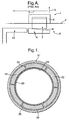
- One form of seal comprises a number of seal segments which are assembled and associated about a shaft to form a seal together. The segments are generally secured in a housing and utilise a circumferential spring to create inward sealing force and pressure. Typically, previous practice was to use a tapered mandrel to lead to static seal element on to a seal runner or other seal surface. Prior art figure A attached schematically illustrates such a
seal assembly arrangement 1 as a side cross-section. In thearrangement 1 there is aseal segment 2 in ahousing 3 which itself is secured in awall portion 4. As indicated above theseal segment 2 is slightly displaceable in a radial outward direction indicated by arrowhead 5 against a bias circumferential spring. In such circumstances, atapered mandrel 6 can ease the seal segment outwardly in the direction 5 when the arrangement is assembled by relative movement in a direction of assembly shown by arrowhead 7. The outward movement means that a sealingsurface 9 of thesegment 2 can engage aseal runner 10 in use to form a seal. It will be understood that generally there will be a number of segments all moved outwardly to a diameter to allow entry of therunner 10 and subsequent withdrawal of themandrel 6. - It will be understood in some situations it may not be practical to use a tapered mandrel. Thus, in such circumstances it is the practice to arrange the axial locations of the seal and bearing components so that the shaft bearings engage before the seal elements. Such an arrangement ensures that the mis-alignment of the seal element is limited to the working clearances in the bearings and their location.
- In addition to the problems of assembly as outlined above it will be understood that there is no protection against damage for the seal elements as a result of the engagement with the seal runner. This limits design choices for the seal runner in order to limit the prospects of damage. It will be understood that in many situations it may not be possible to use a sympathetic long tapered mandrel due to space constraints during assembly. Thus the seal surface maybe damaged on assembly leading to potential failure of the seal arrangement.
- In accordance with the present invention there is provided a method of assembly of a seal arrangement, the method comprising presenting a mandrel to a seal arrangement to radially expand a seal to an expanded state by opening gaps in the seal to a diameter sufficient to accommodate a seal surface against which the seal acts in use, the method characterised in that the gaps are packed with a sacrificial material to retain the expanded state whilst the seal is associated with the seal after the mandrel is removed.
- Generally, the arrangement is heated to remove the sacrificial material when the sacrificial material is a low temperature wax. Typically, the heating is provided by normal in use operational temperatures for the seal arrangement.
- Possibly, the arrangement is washed in a solvent to remove the sacrificial material when the sacrificial material is soluble.
- Also in accordance with the present invention there is provided a seal arrangement for a shaft, the arrangement comprising a seal for location dialation seal radially expandable by opening of gaps in the seal for assembly of the seal arrangement, the arrangement characterised in that the gaps are filled with a sacrificial material to retain expansion of the seal for the assembly of the seal and the sacrificial material is removable once assembled.
- Typically, the seal comprises a plurality of seal segments with gaps between them. Generally, the seal segments are associated with bias for inward sealing pressure in use against a sealing surface. Normally, the bias is provided by a circumferential spring.
- Typically the seal is dilated by expansion. Normally, the seal is expanded to allow assembly to a seal surface.
- Normally, the seal surface is a seal runner.
- Typically, the sacrificial material is a low melting temperature wax. Alternatively, the sacrificial material is soluble in a wash solvent.
- Embodiments of the present invention will now be described by way of example only with reference to the accompanying drawings in which:-
- Figure 1 is a schematic front view of a seal arrangement including a seal and a rotating element such as a shaft;
- Figure 2 is a schematic cross-section through a part of the arrangement shown in Figure 1; and,
- Figure 3 is a schematic front view of the seal arrangement shown in Figure 1 and Figure 2 in use and in a dis-assembled state.
- Generally, a seal arrangement comprises a number of seal segments. The static component part of the seal arrangement thus has a number of seal segments. Each segment is associated with other segments to form a circle which in use will substantially extend around a shaft. The seal segments are held in a housing which provides axial location and some radial restraint to define the limits of seal travel. In use, the seal segments are forced inwards by a circumferential spring so that here is sealing pressure created against a sealing surface of a rotating element or seal runner.
- Figures 1 and 2 schematically depict a seal arrangement about a rotating element such as a shaft in an engine or other machine. Thus, a
housing 21 supports, secures and presents a plurality ofseal segments 22 to aseal surface 23 in this case in the form of a seal runner. As indicated above normally there is an inward bias provided by a circumferential spring or similar so that there is a sealing pressure between aseal surface 24 of thesegments 22 and an opposed part of theseal surface 23. - It will be understood that damage to the seal arrangement upon assemble particularly with respect to the
seal surface 24 will be detrimental to overall seal efficiency. Such damage may occur through in appropriate use of a tapered mandrel and premature contact between thesegments 22 and other parts of the seal arrangement such as features of a seal runner. Ideally, it should be possible to assemble the seal segments on the seal surface, whether a rotating shaft or a seal runner, with a reduced possibility of damage and if possible without use of a mandrel in situ in view of normal space problems. - In the present seal
arrangement seal segments 22 are assembled into theirhousing 21 with a bias spring away from the location where the arrangement will be used. Thus, it will be generally be more convenient to use a tapered mandrel to expand the seal so that gaps open between thesegments 22 and the open diameter of the seal increases and dilates to a size sufficient to allow easy association with seal a surface during later stages of the method of assembly. - With the present arrangements the expanded state of the seal arrangement is retained by a sacrificial material filling to the
gaps 25 between thesegments 22. Thus, when the mandrel is removed the expanded state is maintained to allow entry and other association of the seal about aseal surface 23. - Clearly, the purpose of a seal arrangement is to provide a sealing pressure against the sealing
surface 24. This will not occur if the effect of a pressure bias spring is inhibited by the filling of sacrificial material in thegaps 25. Thus, in the present seal arrangement the sacrificial material is readily removed. - In a preferred embodiment the sacrificial material is a low melting point wax or similar material. Thus, as the sealing arrangement temperature warms in normal operational use the wax will melt and flow out of the
gaps 25 leaving the segments free to be biased inwardly towards the seal surface to create a seal. In such circumstances, it is important to use a suitable wax so that the wax melts in the right temperature range and without too much fractionation with higher melting point waxes remaining in thegaps 25 or elsewhere in the arrangement. It will be understood that the melted wax will be carried away by the fluid being controlled by the seal arrangement. The wax may be soluble in the controlled fluid or not so that any solidified globules of wax can be removed by an appropriate filter. - An alternative for the sacrificial material is that it may be soluble in a specific solvent introduced for the purpose or the fluid controlled by the seal arrangement. Thus, the sacrificial material may be removed by dissolving it in the solvent or fluid.
- An example sacrificial material in-fill 26 is shown in Figure 1 in one of the
gaps 25. Thus, as can be seen the seal is expanded to the expanded stage of a greater diameter than theseal surface 23 or runner minimising the risk of contact between theseal surface 23 and theseal 22 during assembly. - In Figure 3 as can be seen the
seal surface 24 is provided by a seal runner and this is engaged by theseal surface 24 of theseal segment 22. Thehousing 21 provides for axial restraint of thesegment 22 and allows only limited radial displacement into and out of thehousing 21. The radial displacement as indicated is generally controlled by a biasing spring or other mechanism in order to ensure there is good sealing pressure between thesurface 24 and thesurface 23. - Figure 3 provides a schematic illustration of the
seal comprising segments 22 in an assembled and dis-assembled state. The sealing surface provided by the rotating element or seal runner is removed for clarity. - In a dis-assembled state the
segments 22 reach their limit of inward movement when they reach a stop or more normally when ends of thesegments 22 abut against each other. This abutment between thesegments 22 is shown in Figure 3 by the solid lines. In this dis-assembled state the ends of thesegments 22 touch and a continuous circular surface formed. This circular surface is of a diameter smaller than that of the rotating shaft or seal runner. Thus, with the spring bias there will be a sealing pressure generated. - Correct seal segment position is shown by the broken lines. It will be noted that the segments drop to a significantly smaller diameter to generate with the bias spring sufficient seal pressure for the arrangement.
- It will be understood that the sacrificial material will generally be malleable and so when the mandrel is removed there may be some squeezing of the sacrificial material but the expanded stage will be substantially retained. The squeezing effect may be used to expedite remove of the sacrificial material once assembly is complete.
- After the sacrificial material is removed the seal assembly will act like a typical segmented seal arrangement with the seal segments engaging the seal surface with a seal pressure generated by a circumfunctional spray or similar mechanism
- Modifications and adaptations of the present seal arrangement will be appreciated by those skilled in the technology. Thus, the sacrificial material may comprise a single wax or a number of waxes or be reinforced with micro-encapsulated solvents/agents or other means to expedite removal of the sacrificial material. These solvents and agents may act to keep the sacrificial material in solution or to prevent retention of a detrimental retained surface film of sacrificial material which may undermine seal efficiency. The segments may include effective guttering channels to guide removal of the molten or exuding sacrificial material and possibly prevention/inhibit sacrificial material becoming deposited on the sealing surfaces.
Claims (15)
- A method of assembly of a seal arrangement, the method comprising presenting a mandrel to a seal arrangement to radially expand a seal (22) to an expanded state by opening gaps (25) in the seal (22) to a diameter sufficient to accommodate a seal surface (23) against which the seal acts in use, the method characterised in that the gaps (25) are packed with a sacrificial material (26) to retain the expanded state whilst the seal (22) is associated with the seal surface (23) after the mandrel is removed.
- A method as claimed in claim 1 wherein the arrangement is heated to remove the sacrificial material (26) when the sacrificial material (26) is a low temperature wax.
- A method as claimed in claim 2 wherein the heating is provided by normal in use operational temperatures for the seal arrangement.
- A method as claimed in claim 1 wherein the arrangement is washed in a solvent to remove the sacrificial material (26) when the sacrificial material (26) is soluble.
- A seal arrangement for a shaft, the arrangement compressing a seal for location dilation seal radially expandable by opening of gaps (25) in the seal (22) for assembly of the seal arrangement, the arrangement characterised in that the gaps (25) are filled with a sacrificial material (26) to retain expansion of the seal for the assembly of the seal and the sacrificial material is removable once assembled.
- An arrangement as claimed in claim 5 the seal comprises a plurality of seal segments (22) with gaps (25) between them.
- An arrangement as claimed in claim 6 wherein the seal segments are associated with bias for inward sealing pressure in use against a sealing surface.
- An arrangement as claimed in claim 7 wherein the bias is provided by a circumferential spring.
- An arrangement as claimed in any of claims 5 to 8 wherein the seal is dilated by expansion.
- An arrangement as claimed in any of claims 5 to 9 wherein the seal is expanded to allow assembly to a seal surface (24).
- An arrangement as claimed in claimed claim 9 wherein seal surface is a seal runner.
- An arrangement as claimed in any of claims 5 to 11 wherein the sacrificial material is a low melting temperature wax
- An arrangement as claimed in any of claims 5 to 11 wherein the sacrificial material is soluble in a wash solvent.
- A machine incorporating a seal arrangement as claimed in any of claims 5 to 13.
- A machine as claimed in claim 14 wherein the machine is a gas turbine engine.
Applications Claiming Priority (1)
| Application Number | Priority Date | Filing Date | Title |
|---|---|---|---|
| GBGB0517833.0A GB0517833D0 (en) | 2005-09-02 | 2005-09-02 | A seal arrangement and a method of seal assembly |
Publications (3)
| Publication Number | Publication Date |
|---|---|
| EP1760373A2 true EP1760373A2 (en) | 2007-03-07 |
| EP1760373A3 EP1760373A3 (en) | 2008-02-27 |
| EP1760373B1 EP1760373B1 (en) | 2010-03-31 |
Family
ID=35220714
Family Applications (1)
| Application Number | Title | Priority Date | Filing Date |
|---|---|---|---|
| EP06254072A Ceased EP1760373B1 (en) | 2005-09-02 | 2006-08-03 | A seal arrangement and a method of seal assembly |
Country Status (4)
| Country | Link |
|---|---|
| US (1) | US7726940B2 (en) |
| EP (1) | EP1760373B1 (en) |
| DE (1) | DE602006013239D1 (en) |
| GB (1) | GB0517833D0 (en) |
Cited By (1)
| Publication number | Priority date | Publication date | Assignee | Title |
|---|---|---|---|---|
| CN108032251A (en) * | 2017-12-11 | 2018-05-15 | 中国航发南方工业有限公司 | Nozzle ring outer shroud mounting tool |
Families Citing this family (18)
| Publication number | Priority date | Publication date | Assignee | Title |
|---|---|---|---|---|
| US7905495B2 (en) * | 2007-11-29 | 2011-03-15 | Rolls-Royce Corporation | Circumferential sealing arrangement |
| US9004495B2 (en) | 2008-09-15 | 2015-04-14 | Stein Seal Company | Segmented intershaft seal assembly |
| WO2013191718A1 (en) * | 2012-06-19 | 2013-12-27 | Stein Seal Company | Segmented intershaft seal assembly |
| US8820752B2 (en) | 2008-09-15 | 2014-09-02 | Stein Seal Company | Intershaft seal with centrifugal compensation |
| US8151422B2 (en) * | 2008-09-23 | 2012-04-10 | Pratt & Whitney Canada Corp. | Guide tool and method for assembling radially loaded vane assembly of gas turbine engine |
| US8740225B2 (en) * | 2009-06-03 | 2014-06-03 | Exponential Technologies, Inc. | Hydrodynamic bore seal |
| CN102410106B (en) * | 2011-11-28 | 2013-03-13 | 北京动力机械研究所 | High-temperature sealing method of special-shaped cavity used for ramjet |
| US9790863B2 (en) | 2013-04-05 | 2017-10-17 | Honeywell International Inc. | Fluid transfer seal assemblies, fluid transfer systems, and methods for transferring process fluid between stationary and rotating components using the same |
| US10161256B2 (en) | 2015-01-22 | 2018-12-25 | Untied Technologies Corporation | Seal with backup seal |
| US10215098B2 (en) * | 2015-01-22 | 2019-02-26 | United Technologies Corporation | Bearing compartment seal |
| US10570763B2 (en) * | 2015-06-22 | 2020-02-25 | United Technologies Corporation | Gas turbine engine seal installation protection |
| WO2016179608A2 (en) * | 2016-04-29 | 2016-11-10 | Stein Seal Company | Intershaft seal with asymmetric sealing ring |
| US10598035B2 (en) * | 2016-05-27 | 2020-03-24 | General Electric Company | Intershaft sealing systems for gas turbine engines and methods for assembling the same |
| JP2021507163A (en) | 2017-12-13 | 2021-02-22 | エクスポネンシャル テクノロジーズ, インコーポレイテッドExponential Technologies, Inc. | Rotary fluid flow device |
| CN109163158B (en) * | 2018-09-26 | 2020-06-12 | 济宁高新公用事业发展股份有限公司 | A dual-flow metal pipe joint for mixed flow of cold and hot water based on thermal expansion and cooling |
| US12013035B2 (en) | 2019-02-25 | 2024-06-18 | Federal-Mogul Motorparts Llc | Cylinder head gasket assembly |
| US11168683B2 (en) | 2019-03-14 | 2021-11-09 | Exponential Technologies, Inc. | Pressure balancing system for a fluid pump |
| EP3919785B1 (en) * | 2020-06-05 | 2023-08-23 | Trelleborg Sealing Solutions U.S., Inc. | Seal assembly and manufacturing method thereof |
Citations (2)
| Publication number | Priority date | Publication date | Assignee | Title |
|---|---|---|---|---|
| GB2096246A (en) | 1981-04-07 | 1982-10-13 | Fenner Co Ltd J H | Seals |
| GB2368100A (en) | 2000-10-19 | 2002-04-24 | Rolls Royce Plc | Seal fitting |
Family Cites Families (9)
| Publication number | Priority date | Publication date | Assignee | Title |
|---|---|---|---|---|
| US1309075A (en) * | 1919-07-08 | Planookapfj co | ||
| US3001806A (en) * | 1954-10-14 | 1961-09-26 | Macks Elmer Fred | Seal |
| US4082296A (en) * | 1976-05-26 | 1978-04-04 | Stein Philip C | Seal for sealing between a rotating member and a housing |
| US4365817A (en) * | 1981-04-17 | 1982-12-28 | Williams Research Corporation | Self aligning segmented shaft seal |
| US5618048A (en) * | 1988-03-24 | 1997-04-08 | Moriarty; Maurice J. | Piston ring seal having angled ends |
| US5509664A (en) * | 1993-07-19 | 1996-04-23 | Stein Seal Company | Segmented hydrodynamic seals for sealing a rotatable shaft |
| GB9900102D0 (en) * | 1999-01-06 | 1999-02-24 | Rolls Royce Plc | A seal arrangement |
| US6431550B1 (en) * | 2000-09-25 | 2002-08-13 | General Electric Company | Hydrogen seal ring having seal at ring intersegment |
| US6644667B2 (en) * | 2001-02-23 | 2003-11-11 | Cmg Tech, Llc | Seal assembly and rotary machine containing such seal |
-
2005
- 2005-09-02 GB GBGB0517833.0A patent/GB0517833D0/en not_active Ceased
-
2006
- 2006-08-03 EP EP06254072A patent/EP1760373B1/en not_active Ceased
- 2006-08-03 DE DE602006013239T patent/DE602006013239D1/en active Active
- 2006-08-04 US US11/498,715 patent/US7726940B2/en not_active Expired - Fee Related
Patent Citations (2)
| Publication number | Priority date | Publication date | Assignee | Title |
|---|---|---|---|---|
| GB2096246A (en) | 1981-04-07 | 1982-10-13 | Fenner Co Ltd J H | Seals |
| GB2368100A (en) | 2000-10-19 | 2002-04-24 | Rolls Royce Plc | Seal fitting |
Cited By (2)
| Publication number | Priority date | Publication date | Assignee | Title |
|---|---|---|---|---|
| CN108032251A (en) * | 2017-12-11 | 2018-05-15 | 中国航发南方工业有限公司 | Nozzle ring outer shroud mounting tool |
| CN108032251B (en) * | 2017-12-11 | 2020-03-24 | 中国航发南方工业有限公司 | Turbine guider outer ring installation frock |
Also Published As
| Publication number | Publication date |
|---|---|
| GB0517833D0 (en) | 2005-10-12 |
| US20070052179A1 (en) | 2007-03-08 |
| US7726940B2 (en) | 2010-06-01 |
| EP1760373A3 (en) | 2008-02-27 |
| EP1760373B1 (en) | 2010-03-31 |
| DE602006013239D1 (en) | 2010-05-12 |
Similar Documents
| Publication | Publication Date | Title |
|---|---|---|
| US7726940B2 (en) | Seal arrangement and a method of seal assembly | |
| EP2157289B1 (en) | Pumping impeller oil seal | |
| US3537713A (en) | Wear-resistant labyrinth seal | |
| JP4509385B2 (en) | Operation method of gas turbine | |
| EP3445982B1 (en) | Fluid-filled damper for gas bearing assembly | |
| EP2568121A1 (en) | Stepped conical honeycomb seal carrier and corresponding annular seal | |
| US9551233B2 (en) | Labyrinth seal and rotating machine comprising such a seal | |
| EP3252280B1 (en) | Circumferential plenum for oil damper | |
| EP3163017B1 (en) | Intershaft seal assembly | |
| US11181009B2 (en) | Assembly for a turbomachine | |
| EP3575644B1 (en) | Sliding seal | |
| US20160003085A1 (en) | Turbine engine adaptive low leakage air seal | |
| US20110285090A1 (en) | Seal assembly including plateau and concave portion in mating surface for seal tooth in turbine | |
| US10570763B2 (en) | Gas turbine engine seal installation protection | |
| US11773747B2 (en) | Device for detecting cooling abnormalities for an aircraft turbine engine | |
| EP3045708B1 (en) | Gas turbine engine with an upper frame and method of preventing air leakage | |
| US10364679B2 (en) | Gas turbine engine compressor rotor vaporization cooling | |
| EP2014408B1 (en) | Method of repairing knife edge seals | |
| US20180017101A1 (en) | Hydrodynamic bearing | |
| EP3653845B1 (en) | Hydrostatic non-contact seal with access window openings | |
| EP2905427B1 (en) | Gas turbine engine sealing arrangement | |
| JPH05296004A (en) | Shaft seal device for expansion turbine | |
| EP1168139A2 (en) | Computer system | |
| JPH0478805B2 (en) |
Legal Events
| Date | Code | Title | Description |
|---|---|---|---|
| PUAI | Public reference made under article 153(3) epc to a published international application that has entered the european phase |
Free format text: ORIGINAL CODE: 0009012 |
|
| AK | Designated contracting states |
Kind code of ref document: A2 Designated state(s): AT BE BG CH CY CZ DE DK EE ES FI FR GB GR HU IE IS IT LI LT LU LV MC NL PL PT RO SE SI SK TR |
|
| AX | Request for extension of the european patent |
Extension state: AL BA HR MK YU |
|
| PUAL | Search report despatched |
Free format text: ORIGINAL CODE: 0009013 |
|
| AK | Designated contracting states |
Kind code of ref document: A3 Designated state(s): AT BE BG CH CY CZ DE DK EE ES FI FR GB GR HU IE IS IT LI LT LU LV MC NL PL PT RO SE SI SK TR |
|
| AX | Request for extension of the european patent |
Extension state: AL BA HR MK YU |
|
| 17P | Request for examination filed |
Effective date: 20080214 |
|
| 17Q | First examination report despatched |
Effective date: 20080410 |
|
| AKX | Designation fees paid |
Designated state(s): DE FR GB |
|
| GRAP | Despatch of communication of intention to grant a patent |
Free format text: ORIGINAL CODE: EPIDOSNIGR1 |
|
| GRAS | Grant fee paid |
Free format text: ORIGINAL CODE: EPIDOSNIGR3 |
|
| GRAA | (expected) grant |
Free format text: ORIGINAL CODE: 0009210 |
|
| AK | Designated contracting states |
Kind code of ref document: B1 Designated state(s): DE FR GB |
|
| REG | Reference to a national code |
Ref country code: GB Ref legal event code: FG4D |
|
| REF | Corresponds to: |
Ref document number: 602006013239 Country of ref document: DE Date of ref document: 20100512 Kind code of ref document: P |
|
| PLBE | No opposition filed within time limit |
Free format text: ORIGINAL CODE: 0009261 |
|
| STAA | Information on the status of an ep patent application or granted ep patent |
Free format text: STATUS: NO OPPOSITION FILED WITHIN TIME LIMIT |
|
| 26N | No opposition filed |
Effective date: 20110104 |
|
| REG | Reference to a national code |
Ref country code: FR Ref legal event code: PLFP Year of fee payment: 10 |
|
| REG | Reference to a national code |
Ref country code: FR Ref legal event code: PLFP Year of fee payment: 11 |
|
| REG | Reference to a national code |
Ref country code: FR Ref legal event code: PLFP Year of fee payment: 12 |
|
| PGFP | Annual fee paid to national office [announced via postgrant information from national office to epo] |
Ref country code: FR Payment date: 20170825 Year of fee payment: 12 Ref country code: DE Payment date: 20170829 Year of fee payment: 12 Ref country code: GB Payment date: 20170829 Year of fee payment: 12 |
|
| REG | Reference to a national code |
Ref country code: DE Ref legal event code: R119 Ref document number: 602006013239 Country of ref document: DE |
|
| GBPC | Gb: european patent ceased through non-payment of renewal fee |
Effective date: 20180803 |
|
| PG25 | Lapsed in a contracting state [announced via postgrant information from national office to epo] |
Ref country code: DE Free format text: LAPSE BECAUSE OF NON-PAYMENT OF DUE FEES Effective date: 20190301 |
|
| PG25 | Lapsed in a contracting state [announced via postgrant information from national office to epo] |
Ref country code: FR Free format text: LAPSE BECAUSE OF NON-PAYMENT OF DUE FEES Effective date: 20180831 |
|
| PG25 | Lapsed in a contracting state [announced via postgrant information from national office to epo] |
Ref country code: GB Free format text: LAPSE BECAUSE OF NON-PAYMENT OF DUE FEES Effective date: 20180803 |