EP1760299B1 - Control system for internal combustion engine - Google Patents
Control system for internal combustion engine Download PDFInfo
- Publication number
- EP1760299B1 EP1760299B1 EP06017666A EP06017666A EP1760299B1 EP 1760299 B1 EP1760299 B1 EP 1760299B1 EP 06017666 A EP06017666 A EP 06017666A EP 06017666 A EP06017666 A EP 06017666A EP 1760299 B1 EP1760299 B1 EP 1760299B1
- Authority
- EP
- European Patent Office
- Prior art keywords
- cetane number
- engine
- fuel
- ignition timing
- control
- Prior art date
- Legal status (The legal status is an assumption and is not a legal conclusion. Google has not performed a legal analysis and makes no representation as to the accuracy of the status listed.)
- Expired - Fee Related
Links
- 238000002485 combustion reaction Methods 0.000 title claims description 41
- CIWBSHSKHKDKBQ-JLAZNSOCSA-N Ascorbic acid Chemical compound OC[C@H](O)[C@H]1OC(=O)C(O)=C1O CIWBSHSKHKDKBQ-JLAZNSOCSA-N 0.000 claims description 152
- 239000000446 fuel Substances 0.000 claims description 120
- 238000002347 injection Methods 0.000 claims description 88
- 239000007924 injection Substances 0.000 claims description 88
- 239000007789 gas Substances 0.000 claims description 62
- 238000012937 correction Methods 0.000 claims description 41
- 238000006243 chemical reaction Methods 0.000 claims description 33
- 238000000034 method Methods 0.000 claims description 21
- 230000006835 compression Effects 0.000 claims description 19
- 238000007906 compression Methods 0.000 claims description 19
- UNJFKXSSGBWRBZ-BJCIPQKHSA-N ceftibuten Chemical compound S1C(N)=NC(C(=C\CC(O)=O)\C(=O)N[C@@H]2C(N3C(=CCS[C@@H]32)C(O)=O)=O)=C1 UNJFKXSSGBWRBZ-BJCIPQKHSA-N 0.000 claims description 17
- 238000001124 conductive atomic force microscopy Methods 0.000 claims description 16
- 230000008569 process Effects 0.000 claims description 13
- 101100327480 Nicotiana tabacum CET2 gene Proteins 0.000 claims description 11
- 101150072317 CET1 gene Proteins 0.000 claims description 10
- 230000007246 mechanism Effects 0.000 claims description 7
- 230000003134 recirculating effect Effects 0.000 claims description 3
- 230000008859 change Effects 0.000 description 19
- 238000001514 detection method Methods 0.000 description 17
- 238000010586 diagram Methods 0.000 description 9
- 238000001914 filtration Methods 0.000 description 8
- 101100059533 Capsicum annuum CAFP gene Proteins 0.000 description 4
- 239000002826 coolant Substances 0.000 description 4
- QVGXLLKOCUKJST-UHFFFAOYSA-N atomic oxygen Chemical compound [O] QVGXLLKOCUKJST-UHFFFAOYSA-N 0.000 description 3
- 230000007423 decrease Effects 0.000 description 3
- 239000001301 oxygen Substances 0.000 description 3
- 229910052760 oxygen Inorganic materials 0.000 description 3
- 238000012935 Averaging Methods 0.000 description 2
- 101000596041 Homo sapiens Plastin-1 Proteins 0.000 description 2
- 102100035181 Plastin-1 Human genes 0.000 description 2
- 238000001816 cooling Methods 0.000 description 2
- 230000000977 initiatory effect Effects 0.000 description 2
- VNWKTOKETHGBQD-UHFFFAOYSA-N methane Chemical compound C VNWKTOKETHGBQD-UHFFFAOYSA-N 0.000 description 2
- 230000003247 decreasing effect Effects 0.000 description 1
- 230000003111 delayed effect Effects 0.000 description 1
- 230000006866 deterioration Effects 0.000 description 1
- 239000002283 diesel fuel Substances 0.000 description 1
- 230000006870 function Effects 0.000 description 1
- 230000012447 hatching Effects 0.000 description 1
- 239000000203 mixture Substances 0.000 description 1
- 238000012986 modification Methods 0.000 description 1
- 230000004048 modification Effects 0.000 description 1
- 239000003345 natural gas Substances 0.000 description 1
- 238000011017 operating method Methods 0.000 description 1
- 238000012545 processing Methods 0.000 description 1
- 238000011144 upstream manufacturing Methods 0.000 description 1
Images


Classifications
-
- F—MECHANICAL ENGINEERING; LIGHTING; HEATING; WEAPONS; BLASTING
- F02—COMBUSTION ENGINES; HOT-GAS OR COMBUSTION-PRODUCT ENGINE PLANTS
- F02D—CONTROLLING COMBUSTION ENGINES
- F02D41/00—Electrical control of supply of combustible mixture or its constituents
- F02D41/0025—Controlling engines characterised by use of non-liquid fuels, pluralities of fuels, or non-fuel substances added to the combustible mixtures
- F02D41/0047—Controlling exhaust gas recirculation [EGR]
- F02D41/005—Controlling exhaust gas recirculation [EGR] according to engine operating conditions
-
- F—MECHANICAL ENGINEERING; LIGHTING; HEATING; WEAPONS; BLASTING
- F02—COMBUSTION ENGINES; HOT-GAS OR COMBUSTION-PRODUCT ENGINE PLANTS
- F02D—CONTROLLING COMBUSTION ENGINES
- F02D19/00—Controlling engines characterised by their use of non-liquid fuels, pluralities of fuels, or non-fuel substances added to the combustible mixtures
- F02D19/06—Controlling engines characterised by their use of non-liquid fuels, pluralities of fuels, or non-fuel substances added to the combustible mixtures peculiar to engines working with pluralities of fuels, e.g. alternatively with light and heavy fuel oil, other than engines indifferent to the fuel consumed
- F02D19/0602—Control of components of the fuel supply system
- F02D19/0607—Control of components of the fuel supply system to adjust the fuel mass or volume flow
- F02D19/061—Control of components of the fuel supply system to adjust the fuel mass or volume flow by controlling fuel injectors
-
- F—MECHANICAL ENGINEERING; LIGHTING; HEATING; WEAPONS; BLASTING
- F02—COMBUSTION ENGINES; HOT-GAS OR COMBUSTION-PRODUCT ENGINE PLANTS
- F02D—CONTROLLING COMBUSTION ENGINES
- F02D19/00—Controlling engines characterised by their use of non-liquid fuels, pluralities of fuels, or non-fuel substances added to the combustible mixtures
- F02D19/06—Controlling engines characterised by their use of non-liquid fuels, pluralities of fuels, or non-fuel substances added to the combustible mixtures peculiar to engines working with pluralities of fuels, e.g. alternatively with light and heavy fuel oil, other than engines indifferent to the fuel consumed
- F02D19/0626—Measuring or estimating parameters related to the fuel supply system
- F02D19/0634—Determining a density, viscosity, composition or concentration
- F02D19/0636—Determining a density, viscosity, composition or concentration by estimation, i.e. without using direct measurements of a corresponding sensor
-
- F—MECHANICAL ENGINEERING; LIGHTING; HEATING; WEAPONS; BLASTING
- F02—COMBUSTION ENGINES; HOT-GAS OR COMBUSTION-PRODUCT ENGINE PLANTS
- F02D—CONTROLLING COMBUSTION ENGINES
- F02D19/00—Controlling engines characterised by their use of non-liquid fuels, pluralities of fuels, or non-fuel substances added to the combustible mixtures
- F02D19/06—Controlling engines characterised by their use of non-liquid fuels, pluralities of fuels, or non-fuel substances added to the combustible mixtures peculiar to engines working with pluralities of fuels, e.g. alternatively with light and heavy fuel oil, other than engines indifferent to the fuel consumed
- F02D19/0639—Controlling engines characterised by their use of non-liquid fuels, pluralities of fuels, or non-fuel substances added to the combustible mixtures peculiar to engines working with pluralities of fuels, e.g. alternatively with light and heavy fuel oil, other than engines indifferent to the fuel consumed characterised by the type of fuels
- F02D19/0649—Liquid fuels having different boiling temperatures, volatilities, densities, viscosities, cetane or octane numbers
-
- F—MECHANICAL ENGINEERING; LIGHTING; HEATING; WEAPONS; BLASTING
- F02—COMBUSTION ENGINES; HOT-GAS OR COMBUSTION-PRODUCT ENGINE PLANTS
- F02D—CONTROLLING COMBUSTION ENGINES
- F02D41/00—Electrical control of supply of combustible mixture or its constituents
- F02D41/0025—Controlling engines characterised by use of non-liquid fuels, pluralities of fuels, or non-fuel substances added to the combustible mixtures
-
- F—MECHANICAL ENGINEERING; LIGHTING; HEATING; WEAPONS; BLASTING
- F02—COMBUSTION ENGINES; HOT-GAS OR COMBUSTION-PRODUCT ENGINE PLANTS
- F02D—CONTROLLING COMBUSTION ENGINES
- F02D41/00—Electrical control of supply of combustible mixture or its constituents
- F02D41/30—Controlling fuel injection
- F02D41/38—Controlling fuel injection of the high pressure type
- F02D41/40—Controlling fuel injection of the high pressure type with means for controlling injection timing or duration
- F02D41/401—Controlling injection timing
-
- F—MECHANICAL ENGINEERING; LIGHTING; HEATING; WEAPONS; BLASTING
- F02—COMBUSTION ENGINES; HOT-GAS OR COMBUSTION-PRODUCT ENGINE PLANTS
- F02D—CONTROLLING COMBUSTION ENGINES
- F02D2200/00—Input parameters for engine control
- F02D2200/02—Input parameters for engine control the parameters being related to the engine
- F02D2200/06—Fuel or fuel supply system parameters
- F02D2200/0611—Fuel type, fuel composition or fuel quality
- F02D2200/0612—Fuel type, fuel composition or fuel quality determined by estimation
-
- F—MECHANICAL ENGINEERING; LIGHTING; HEATING; WEAPONS; BLASTING
- F02—COMBUSTION ENGINES; HOT-GAS OR COMBUSTION-PRODUCT ENGINE PLANTS
- F02D—CONTROLLING COMBUSTION ENGINES
- F02D2250/00—Engine control related to specific problems or objectives
- F02D2250/32—Air-fuel ratio control in a diesel engine
-
- F—MECHANICAL ENGINEERING; LIGHTING; HEATING; WEAPONS; BLASTING
- F02—COMBUSTION ENGINES; HOT-GAS OR COMBUSTION-PRODUCT ENGINE PLANTS
- F02D—CONTROLLING COMBUSTION ENGINES
- F02D41/00—Electrical control of supply of combustible mixture or its constituents
- F02D41/24—Electrical control of supply of combustible mixture or its constituents characterised by the use of digital means
- F02D41/2406—Electrical control of supply of combustible mixture or its constituents characterised by the use of digital means using essentially read only memories
- F02D41/2409—Addressing techniques specially adapted therefor
- F02D41/2422—Selective use of one or more tables
-
- F—MECHANICAL ENGINEERING; LIGHTING; HEATING; WEAPONS; BLASTING
- F02—COMBUSTION ENGINES; HOT-GAS OR COMBUSTION-PRODUCT ENGINE PLANTS
- F02M—SUPPLYING COMBUSTION ENGINES IN GENERAL WITH COMBUSTIBLE MIXTURES OR CONSTITUENTS THEREOF
- F02M26/00—Engine-pertinent apparatus for adding exhaust gases to combustion-air, main fuel or fuel-air mixture, e.g. by exhaust gas recirculation [EGR] systems
- F02M26/02—EGR systems specially adapted for supercharged engines
- F02M26/04—EGR systems specially adapted for supercharged engines with a single turbocharger
- F02M26/05—High pressure loops, i.e. wherein recirculated exhaust gas is taken out from the exhaust system upstream of the turbine and reintroduced into the intake system downstream of the compressor
-
- F—MECHANICAL ENGINEERING; LIGHTING; HEATING; WEAPONS; BLASTING
- F02—COMBUSTION ENGINES; HOT-GAS OR COMBUSTION-PRODUCT ENGINE PLANTS
- F02M—SUPPLYING COMBUSTION ENGINES IN GENERAL WITH COMBUSTIBLE MIXTURES OR CONSTITUENTS THEREOF
- F02M26/00—Engine-pertinent apparatus for adding exhaust gases to combustion-air, main fuel or fuel-air mixture, e.g. by exhaust gas recirculation [EGR] systems
- F02M26/52—Systems for actuating EGR valves
- F02M26/53—Systems for actuating EGR valves using electric actuators, e.g. solenoids
-
- Y—GENERAL TAGGING OF NEW TECHNOLOGICAL DEVELOPMENTS; GENERAL TAGGING OF CROSS-SECTIONAL TECHNOLOGIES SPANNING OVER SEVERAL SECTIONS OF THE IPC; TECHNICAL SUBJECTS COVERED BY FORMER USPC CROSS-REFERENCE ART COLLECTIONS [XRACs] AND DIGESTS
- Y02—TECHNOLOGIES OR APPLICATIONS FOR MITIGATION OR ADAPTATION AGAINST CLIMATE CHANGE
- Y02T—CLIMATE CHANGE MITIGATION TECHNOLOGIES RELATED TO TRANSPORTATION
- Y02T10/00—Road transport of goods or passengers
- Y02T10/10—Internal combustion engine [ICE] based vehicles
- Y02T10/30—Use of alternative fuels, e.g. biofuels
-
- Y—GENERAL TAGGING OF NEW TECHNOLOGICAL DEVELOPMENTS; GENERAL TAGGING OF CROSS-SECTIONAL TECHNOLOGIES SPANNING OVER SEVERAL SECTIONS OF THE IPC; TECHNICAL SUBJECTS COVERED BY FORMER USPC CROSS-REFERENCE ART COLLECTIONS [XRACs] AND DIGESTS
- Y02—TECHNOLOGIES OR APPLICATIONS FOR MITIGATION OR ADAPTATION AGAINST CLIMATE CHANGE
- Y02T—CLIMATE CHANGE MITIGATION TECHNOLOGIES RELATED TO TRANSPORTATION
- Y02T10/00—Road transport of goods or passengers
- Y02T10/10—Internal combustion engine [ICE] based vehicles
- Y02T10/40—Engine management systems
Definitions
- the present invention relates to a control system for an internal combustion engine, and particularly, to a system for controlling an internal combustion engine according to a pressure in the cylinder detected by a cylinder pressure sensor.
- JP '566 discloses a fuel injection control apparatus in which the cylinder pressure (pressure in the combustion chamber) is detected by a cylinder pressure sensor. A fuel injection amount, a fuel injection timing, and the like, are controlled according to the detected cylinder pressure. According to the disclosed apparatus, the crank angle Cmax at which the cylinder pressure reaches the maximum value is detected, and the fuel injection timing is corrected so that the detected crank angle Cmax coincides with a target value which is previously set according to the engine operating condition.
- the control used by the above-described conventional apparatus is effective when the combustion characteristic of the fuel changes.
- Document EP 0 905 361 A2 discloses a combustion control system for a Diesel engine.
- the system comprises a control unit configured to control the ignition timing according to the cetane number of the fuel.
- the cetane number of the fuel is higher than that of a reference fuel
- fuel injection initiation timing is delayed and/or the amount of engine coolant flowing through the EGR gas cooling device is increased.
- fuel injection initiation timing is advanced, the amount of engine coolant flowing through the EGR gas cooling device is decreased, and the EGR rate and/or the turbo charged pressure is increased.
- HCCI homogeneous charge compression ignition
- the HCCI engine uses a primary fuel which is a natural gas of low cetane number and a secondary fuel which is a Diesel fuel of high cetane number added thereto.
- the amount of high cetane fuel added is controlled according to engine speed and load, such as to control the ignition delay. Fuel of different cetane numbers is used to obtain a desired ignition delay for any of engine conditions substantially independent of the EGR rate.
- the "ignition timing” means the compression ignition timing that is a timing of ignition caused not by the spark plug but by the compression of the air-fuel mixture.
- the target ignition timing is calculated according to the engine operating condition
- the ignition delay correction amount is calculated so that the detected actual ignition timing coincides with the target ignition timing
- the fuel injection timing is corrected by the ignition delay correction amount.
- the control value of the amount of exhaust gases being recirculated is calculated using the exhaust gas recirculation control value storing means that stores control values of the amount of exhaust gases recirculated, wherein the stored control values are set according to the engine operating condition, and the amount of exhaust gases being recirculated is controlled using the calculated control value.
- the cetane number of the fuel is estimated using the conversion table storing means which stores the conversion table to be used for converting the ignition delay correction amount to the cetane number of the fuel.
- the exhaust gas recirculation control value storing means used for calculating the control value of the amount of exhaust gases being recirculated is switched according to the estimated cetane number.
- the conversion table storing means used for estimating the cetane number is switched according to the estimated cetane number.
- the exhaust gas recirculation control value storing means storing the control values of the amount of exhaust gases being recirculated is switched according to the estimated cetane number
- the amount of exhaust gases recirculated changes and the ignition delay correction amount also changes. Therefore, the cetane number is accurately estimated by switching the conversion table storing means according to the estimated cetane number. Consequently, the cetane number of the fuel in use is accurately estimated while appropriately controlling the amount of exhaust gases recirculated according to the detected actual ignition timing.
- the plurality of the conversion tables stored in the plurality of conversion table storing means are set based on fuels of different cetane numbers.
- the cetane number estimating means performs the estimation process when the operating condition of the engine is in a premix combustion region.
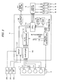
- FIG. 1 is a schematic diagram illustrating an internal combustion engine and a control system therefor according to one embodiment of the present invention
- FIG. 2 is a schematic diagram illustrating a configuration of a part of the control system illustrated in FIG. 1 ;
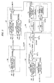
- FIG. 3 is a block diagram illustrating a configuration of a module for calculating a main injection timing (CAIM) and a target exhaust gas recirculation amount (GEGR);
- CAIM main injection timing
- GEGR target exhaust gas recirculation amount
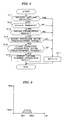
- FIG. 4 is a flowchart illustrating a process for setting a switching control signal (SCTL) supplied to a switching block illustrated in FIG. 3 ;
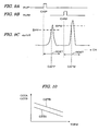
- FIG. 5 is a diagram illustrating a premix combustion region
- FIG. 6 is a diagram illustrating a setting method of a determined cetane number parameter
- FIG. 7 is a block diagram illustrating a configuration of an ignition timing detection block illustrated in FIG. 3 ;
- FIG. 8 is a time chart illustrating a band pass filtering of a cylinder pressure sensor output
- FIGS. 9A - 9C are time charts illustrating a method of detecting an ignition timing.
- FIG. 10 illustrates a table used for calculating a cetane number (CETA, CETB) from an ignition delay time period (TDFM);
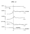
- FIG. 11 is a time chart illustrating the control operation.
- FIGS. 1 and 2 are schematic diagrams illustrating a configuration of an internal combustion engine 1 and a control system therefor according to one embodiment of the present invention.
- the internal combustion engine 1 (hereinafter referred to as "engine"), which has four cylinders, is a diesel engine, wherein fuel is injected directly into the cylinders.
- Each cylinder is provided with a fuel injection valve 6 electrically connected to an electronic control unit 4 (hereinafter referred to as "ECU 4").
- the ECU 4 controls a valve opening period and a valve opening timing of each fuel injection valve 6. That is, the fuel injection period and fuel injection timing are controlled by the ECU 4.
- the engine 1 has an intake pipe 22, an exhaust pipe 24, and a turbocharger 28.
- the turbocharger 28 includes a turbine 30 and a compressor 29.
- the turbine 30 is driven by the kinetic energy of exhaust gases.
- the turbine 30 has a plurality of movable vanes (not shown) and is configured so that the rotational speed of the turbine 30 is adjusted by changing an opening of the movable vanes (hereinafter referred to as "vane opening").
- the vane opening of the turbine 30 is electromagnetically controlled by the ECU 4.
- the intake pipe 22 is provided with an intercooler 25 on a downstream side of the compressor 29 and the intercooler 25 cools pressurized air.
- An exhaust gas recirculation passage 26 for recirculating exhaust gases to the intake pipe 22 is provided between the upstream side of the turbine 30 in the exhaust pipe 24 and the intake pipe 22.
- the exhaust gas recirculation passage 26 is provided with an exhaust gas recirculation control valve 27 (hereinafter referred to as "EGR valve") that controls the amount of exhaust gases that are recirculated.
- the EGR valve 27 is an electromagnetic valve having a solenoid. A valve opening of the EGR valve 27 is controlled by the ECU 4.
- the intake pipe 22 is provided with an intake air flow rate sensor 31 and a boost pressure sensor 32.
- the intake air flow rate sensor 31 detects an intake air flow rate GA.
- the boost pressure sensor 32 detects an intake pressure (boost pressure) PB on the downstream side of the turbocharger 28. The detection signals of the intake air flow rate sensor 31 and the boost pressure sensor 32 are supplied to the ECU 4.
- Each cylinder of the engine 1 is provided with a cylinder pressure sensor 2 for detecting a cylinder pressure (a pressure in the combustion chamber of the engine 1).
- the cylinder pressure sensor 2 is configured in one body together with a grow plug disposed in each cylinder.
- the detection signal of the cylinder pressure sensor 2 is supplied to the ECU 4. It is to be noted that the detection signal of the cylinder pressure sensor 2 corresponds to a differential signal of the cylinder pressure PCYL with respect to the crank angle (time).
- the cylinder pressure PCYL is obtained by integrating the output of the cylinder pressure sensor 2.
- the engine 1 is provided with a crank angle position sensor 3 for detecting a rotation angle of the crankshaft (not shown) of the engine 1.
- the crank angle position sensor 3 generates one pulse at every 1 degree of the crank angle, and the pulse is supplied to the ECU 4.
- the crank angle position sensor 3 further generates a cylinder discrimination pulse at a predetermined crank angle for a specific cylinder of the engine 1 and then supplies the cylinder discrimination pulse to the ECU 4.
- An accelerator sensor 33 for detecting an operation amount AP of the accelerator pedal of the vehicle driven by the engine 1, a coolant temperature sensor 34 for detecting a coolant temperature TW of the engine 1, a vehicle speed sensor 35 for detecting a vehicle speed VP of the vehicle, an oxygen concentration sensor (not shown) for detecting an oxygen concentration in the exhaust gases, and an intake air temperature sensor (not shown) for detecting an intake air temperature TA of the engine 1 are connected to the ECU 4.
- the detection signals of these sensors are supplied to the ECU 4.
- a control signal of the fuel injection valve 6 located in the combustion chamber of each cylinder of the engine 1 is provided by the ECU 4 to a drive circuit 5.
- the drive circuit 5 is connected to the fuel injection valves 6 and supplies drive signals according to the control signal from the ECU 4 to the fuel injection valves 6.
- Fuel is injected into the combustion chamber of each cylinder on a fuel injection timing in accordance with a control signal that is output by the ECU 4.
- the amount of fuel that is injected is controlled to a value in accordance with the control signal from the ECU 4.
- the ECU 4 includes an amplifier 10, an A/D conversion block 11, a pulse generation block 13, a CPU 14 (Central Processing Unit), a ROM 15 (Read Only Memory) for storing programs executed by the CPU 14, a RAM 16 (Random Access Memory) for storing calculation results, and the like, an input circuit 17, and an output circuit 18.
- the detection signal of the cylinder pressure sensor 2 is input to the amplifier 10.
- the amplifier 10 amplifies the input signal.
- the signal amplified by the amplifier 10 is then input to the A/D conversion block 11.
- the pulse signal output from the crank angle position sensor 3 is input to the pulse generation block 13.
- the A/D conversion block 11 which includes a buffer 12, converts the cylinder pressure sensor output from the amplifier 10 to a digital value (hereinafter referred to as "pressure change rate") dp/d ⁇ , and stores the converted digital value in the buffer 12.
- a pulse signal PLS1 (hereinafter referred to as "one-degree pulse”), having a crank angle period of one degree, is supplied to the A/D conversion block 11 from the pulse generation block 13.
- the cylinder pressure sensor output is sampled at the intervals of the one-degree pulse PLS1 and converted to a digital value.
- the digital value is then stored in the buffer 12.
- a pulse signal PLS6 having a crank angle period of six degrees is supplied to the CPU 14 from the pulse generation block 13.
- the CPU 14 performs a process for reading the digital value stored in the buffer 12 at intervals of the six-degree pulse PLS6. That is, in the present embodiment, the A/D conversion block 11 does not request an interrupt to the CPU 14, but the CPU 14 does perform the reading process at intervals of the six-degree pulse PLS6.
- the input circuit 17 converts the detection signals from various sensors to digital values and supplies the digital values to the CPU 14.
- An engine rotational speed NE is calculated from the time period of the six-degree pulse PLS6.
- a demand torque TRQ of the engine 1 is calculated according to the operation amount AP of the accelerator pedal.
- the CPU 14 calculates a target exhaust gas recirculation amount GEGR (hereinafter referred to as "target EGR amount) according to the engine operating condition and supplies a duty control signal to the EGR valve 20 through the output circuit 18 for controlling an opening of the EGR valve 20 according to the target EGR amount.
- target EGR amount a target exhaust gas recirculation amount GEGR
- FIG. 3 is a block diagram illustrating a configuration of a module which calculates a main injection timing CAIM of the fuel injection valve 6 and the target EGR amount GEGR.
- the function of the module is realized by the processes executed by the CPU 14.
- the module of FIG. 3 includes a main injection timing calculation block 36 for calculating the main injection timing CAIM, a target EGR amount GEGR calculation block 37 for calculating the target EGR amount GEGR, an ignition delay correction amount calculation block 38 for detecting an actual ignition timing of the fuel injected into the combustion chamber and for calculating an ignition delay correction amount CADM of the fuel injection timing according to the actual ignition timing, and a cetane number estimation block 39 for estimating a cetane number of the fuel being used according to the ignition delay correction amount CADM to calculate a determined cetane number parameter CETD.
- the determined cetane number parameter CETD is set based on a relationship between the estimated cetane number and a predetermined threshold value and indicates the cetane number of the fuel in use.
- the determined cetane number parameter CETD when the cetane number of the fuel in use is determined to be a first cetane number CET1 (for example, 40) which is relatively low, the determined cetane number parameter CETD is set to "1".
- the cetane number of the fuel in use is determined to be a second cetane number CET2 (for example, 57) which is relatively high, the determined cetane number parameter CETD is set to "2".
- the main injection timing calculation block 36 includes a main injection timing map value calculation block 41 and an adding block 42.
- the main injection timing map value calculation block 41 retrieves a CAIMM map which is previously set according to the engine rotational speed NE and the demand torque TRQ to calculate a main injection timing map value CAIMM.
- the CAIMM map is set based on the fuel of the second cetane number CET2.
- the adding block 42 adds an ignition delay correction amount CADM to the main injection timing map value CAIMM, that is, advances the main injection timing by the ignition delay correction amount CADM to calculate the main injection timing CAIM.
- the target EGR amount calculation block 37 includes a first target EGR amount map value calculation block 51, a second target EGR amount map value calculation block 52, and a switching block 53.
- the first target EGR amount map value calculation block 51 retrieves a GEGRM1 map which is previously set according to the engine rotational speed NE and the demand torque TRQ to calculate a first target EGR amount map value GEGRM1.
- the GEGRM1 map is set based on the fuel of the first cetane number CET1.
- the second target EGR amount map value calculation block 52 retrieves a GEGRM2 map which is previously set according to the engine rotational speed NE and the demand torque TRQ to calculate a second target EGR amount map value GEGRM2.
- the GEGRM2 map is set based on the fuel of the second cetane number CET2.
- the switching block 53 selects the first target EGR amount map value GEGRM1 when the determined cetane number parameter CETD is equal to "1" which indicates that the fuel of the first cetane number CET1 is being used.
- the switching block 53 selects the second target EGR amount map value GEGRM2 when the determined cetane number parameter CETD is equal to "2" which indicates that the fuel of the second cetane number CET2 is being used.
- the selected EGR amount is output as the target EGR amount GEGR. Thereby, the recirculation amount of exhaust gases can be controlled to a value suitable for the cetane number of the fuel in use.
- the ignition delay correction amount calculation block 38 includes a target main injection ignition timing map value calculation block 61, an ignition timing detection block 62, a subtracting block 63, a switching block 64, a filtering block 65, and a PI control block 66.
- the target main injection ignition timing map value calculation block 61 retrieves a CAFMM map which is previously set according to the engine rotational speed NE and the demand torque TRQ to calculate a target main injection ignition timing map value CAFMM.
- the CAFMM map is set based on the fuel of the second cetane number CET2.
- the ignition timing detection block 62 detects a main injection ignition timing CAFM according to the pressure change rate dp/d ⁇ obtained by converting the output signal of the cylinder pressure sensor 2 to a digital value. The detection method thereof will be described later with reference to FIGS. 7 - 9 .
- the subtracting block 63 subtracts the detected main injection ignition timing CAFM from the target main injection ignition timing map value CAFMM to calculate an ignition delay angle DCAM.
- the switching block 64 is on/off controlled by a switching control signal SCTL. Specifically, the switching block 64 is turned off when the switching control signal SCTL is equal to "0" and turned on when the switching control signal SCTL is equal to "1".
- the switching control signal SCTL is set to "1" when a feedback control of the fuel injection timing, that is, a correction of the fuel injection timing with the ignition delay correction amount CADM calculated according to the actual ignition timing CAFM, and a cetane number estimation of the fuel in use are executed. Otherwise, the switching control signal SCTL is set to "0". Consequently, the switching block 64 is turned on when performing the feedback control of the fuel injection timing and the cetane number estimation.
- step S11 of FIG. 4 it is determined whether any one of the sensors, that is, the crank angle position sensor 3, the accelerator sensor 21 and/or the cylinder pressure sensor 2, necessary for the cetane number estimation process, has failed. If the answer to step S11 is affirmative (YES), the switching control signal SCTL is set to "0" (step S17). If no failure of the sensors is detected, it is determined whether the vehicle driven by the engine 1 is running in the steady running state (step S12). If the vehicle is running in the steady running state, it is determined whether the operating condition of the engine 1 is in the premix combustion region (step S13).
- the premix combustion is defined as a combustion in which the injected fuel burns after a delay time period has elapsed from the time of fuel injection.
- the hatching region illustrated in FIG. 5 i.e., the region defined by the demand torque TRQ below the predetermined torque TRQ1, e.g., 60 Nm, and the engine rotational speed NE in the range from a first predetermined rotational speed NE1, e.g., 1200 rpm to a second predetermined rotational speed NE2, e.g., 2300 rpm, is the premix combustion region.
- the change in the ignition timing caused by a change in the cetane number of the fuel becomes relatively large. Therefore, the feedback control of the fuel injection timing based on the ignition delay and the estimation of the cetane number is accurately performed.
- step S13 If the answer to step S13 is affirmative (YES), it is determined whether the boost pressure PB is within a predetermined range, e.g., within the range of ⁇ 5 percent of the target pressure value (step S14). If the answer to step S14 is affirmative (YES), it is determined whether other engine operating parameters are within predetermined ranges which are determined corresponding to each engine operating parameter.
- the detection condition of the cetane number estimation is determined to be satisfied, and the switching control signal SCTL is set to "1" (step S16).
- the switching control signal SCTL is set to "1"
- the switching block 64 is turned on as described above, and the feedback control of the fuel injection timing, that is, the update of the ignition delay correction amount CADM, and the estimation process of the cetane number are performed.
- step S17 If any one of the answers to steps S12 - S15 is negative (NO), the process proceeds to step S17, wherein the switching control signal SCTL is set to "0".
- step S11, S12, and S15 execution of the feedback control of the fuel injection timing, that is, the update of the ignition delay correction amount CADM, and estimation of the cetane number are permitted.
- the change in the ignition timing caused by a change in the cetane number of the fuel becomes relatively large. Therefore, correction of the fuel injection timing based on the ignition delay and estimation of the cetane number are accurately performed.
- the ignition timing of the fuel is easily influenced by a change in the boost pressure. Therefore, by stopping estimation of the cetane number when the boost pressure PB is outside the predetermined range, the inappropriate correction of fuel injection timing caused by a change in characteristics or failure of the turbocharger 28 and the erroneous determination of the cetane number of the fuel are prevented.
- the filtering block 65 performs a filtering operation by using a least-squares method calculation or a moving averaging calculation of data of the ignition delay angle DCAM obtained in a comparatively long time period, e.g., 10 - 60 seconds, to calculate a filtered ignition delay angle DCAMF.
- the PI control block 66 calculates the ignition delay correction amount CADM of the fuel injection timing with the proportional/integral control method so that the ignition delay angle DCAMF may become "0". Specifically, the ignition delay correction amount CADM is set to a greater value as the ignition delay angle DCAMF increases.
- the ignition delay correction amount CADM substantially changes in proportion to the ignition delay angle DCAMF, and the ignition delay correction amount CADM is used to estimate the cetane number of the fuel in use.
- the switching control signal SCTL set in the process of FIG. 4 is equal to "0"
- the PI control block 66 stops updating the ignition delay correction amount CADM and outputs the most recently updated ignition delay correction amount CADM.
- the cetane number estimation block 39 includes a first conversion block 71, a second conversion block 72, a switching block 73, a cetane number learning block 74, and a determination parameter setting block 75.
- the first conversion block 71 converts the ignition delay correction amount CADM to an ignition delay time period TDFM according to the engine rotational speed NE and retrieves a CETA table illustrated in FIG. 10 according to the ignition delay time period TDFM.
- the CETA table is set based on the fuel of the first cetane number CET1.
- the second conversion block 72 converts the ignition delay correction amount CADM to the ignition delay time period TDFM according to the engine rotational speed NE and retrieves a CETB table illustrated in FIG. 10 according to the ignition delay time period TDFM.
- the CETB table is set based on the fuel of the second cetane number CET2. As illustrated in FIG. 10 , if the ignition delay time period TDFM is the same, CETA is less than CETB.
- the switching block 73 is switched according to the determined cetane number parameter CETD. That is, if the determined cetane number parameter CETD is equal to "1", the first converted cetane number CETA is selected. If the determined cetane number parameter CETD is equal to "2", the second converted cetane number CETB is selected. The selected parameter is output as the estimated cetane number CET.
- the cetane number learning block 74 applies the estimated cetane number CET to the following equation (1) to calculate a cetane number learning value CETLRN:
- CETLRN ⁇ ⁇ CET + 1 - ⁇ ⁇ CETLRN
- the cetane number learning value CETLRN described above is calculated using the output from each cylinder pressure sensor of a corresponding cylinder of all, e.g., four, of the cylinders in the engine 1. Therefore, averaging of the cetane number CET detected for each cylinder and the cetane numbers CET whose detection timings are different from each other, is performed by the above-described equation (1).
- the cetane number estimation process is not executed, the most recent cetane number learning value CETLRN of the stored learning values is output from the cetane number learning block 74.
- the determination parameter setting block 75 determines whether the cetane number of fuel being used is the first cetane number CET1 or the second cetane number CET2 according to the cetane number learning value CETLRN. When the determined cetane number is the first cetane number CET1, the determined cetane number parameter CETD is set to "1". When the determined cetane number is the second cetane number CET2, the determined cetane number parameter CETD is set to "2".
- the cetane number learning value CETLRN is compared with a hysteresis threshold value. That is, if a parameter (hereinafter referred to as "hysteresis parameter") for adding the hysteresis is indicated by " ⁇ h", the determined cetane number parameter CETD is changed to "2" when the determined cetane number parameter CETD is equal to "1” and the cetane number learning value CETLRN exceeds the value obtained by adding the hysteresis parameter ⁇ h to the threshold value CETH.
- hysteresis parameter a parameter for adding the hysteresis
- the determined cetane number parameter CETD is changed to "1" when the determined cetane number parameter CETD is equal to "2" and the cetane number learning value CETLRN becomes lower than the value obtained by subtracting the hysteresis parameter ⁇ h from the threshold value CETH.
- FIG. 7 is a block diagram illustrating a configuration of the ignition timing detection block 62 illustrated in FIG. 3 .
- the ignition timing detection block 62 includes a band pass filtering block 91, a phase delay correction block 92, and an ignition timing determination block 93.
- the pressure change rate dp/d ⁇ output from the cylinder pressure sensor 2 is input to the band pass filtering block 91.
- the waveform W1 shows an input waveform and the waveform W2 shows an output waveform.
- the phase delay, which occurs in the band pass filtering block 91, is corrected in the phase delay correction block 92.
- the ignition timing determination block 93 determines a crank angle position CAFP (hereinafter referred to as "pilot injection ignition timing”) at which the pressure change rate dp/d ⁇ takes a peak value corresponding to the pilot injection, and a crank angle position CAFM (hereinafter referred to as “main injection ignition timing”) at which the pressure change rate dp/d ⁇ takes another peak value corresponding to the main injection.
- CAFP crank angle position at which the pressure change rate dp/d ⁇ takes a peak value corresponding to the pilot injection
- main injection ignition timing crank angle position at which the pressure change rate dp/d ⁇ takes another peak value corresponding to the main injection.
- the crank angle position at which the pressure change rate dp/d ⁇ output from the phase delay correction block 92 exceeds a pilot detection threshold value DPP is determined to be the pilot injection ignition timing CAFP
- the crank angle position at which the pressure change rate dp/d ⁇ exceeds a main detection threshold value DPM is determined to be the main injection ignition timing CAFM.
- the main injection ignition timing CAFM is used for estimating the cetane number CET.
- FIGS. 9A and 9B illustrate a pilot injection pulse INJP started from a crank angle position CAIP and a main injection pulse INJM started from a crank angle position CAIM.
- FIG. 9C illustrates an angle position range RDET, e.g., 10 degrees, where the ignition timings CAFP and CAFM are detected. By limiting the detection angle position range RDET to a comparatively narrow range, as illustrated in FIG. 9C , the ignition timing is accurately determined without increasing a calculation load on the CPU 14.
- FIG. 11 is a time chart illustrating the operation when the fuel of a high cetane number is being used, wherein the determined cetane number parameter CETD is set to "2", and the fuel of a low cetane number, e.g., 40, is refueled.
- the execution condition of the feedback control (cetane number estimation) is satisfied at time t0, and the switching control signal SCTL changes from "0" to "1".
- the main injection ignition timing CAFM is in the state where the main injection ignition timing CAFM is late for the target main injection ignition timing CAFMM. Thereafter, the ignition delay correction amount CADM gradually increases, and the main injection ignition timing CAFM gradually advances (increases).
- the cetane number learning value CETLRN gradually decreases corresponding to the increase in the ignition delay correction amount CADM.
- the cetane number learning value becomes less than the predetermined threshold value CETH, that is, CETH- ⁇ h.
- the determined cetane number parameter CETD changes from "2" to "1”
- the target EGR amount GEGR is switched from the second target EGR amount map value GEGRM2 to the first target EGR amount map value GEGRM1. Therefore, recirculation of the exhaust gas is performed at the appropriate flow rate for the fuel in use.
- the switching block 73 is switched from the output of the second conversion block 72 to the output of the first conversion block 71. Also, the conversion table for calculating the cetane number is switched from the CETB table to the CETA table corresponding to a change in the ignition delay angle DCAM due to the change in the amount of exhaust gases being recirculated.
- the cetane number is accurately estimated irrespective of the change in the actual ignition timing caused by the change in the recirculated amount of exhaust gases. Therefore, after time t1, the cetane number learning value CETLRN becomes substantially equal to the first cetane number CET1 and the state is maintained.
- the ignition delay correction amount CADM slightly increases after time t1 due to a delay of change in the actual amount of the exhaust gases recirculated. Thereafter, the ignition delay correction amount CADM gradually decreases as the recirculated amount of the exhaust gases decreases.
- the target main injection ignition timing CAFMM is calculated using the CAFMM map set according to the engine rotational speed NE and the demand torque TRQ.
- the ignition delay correction amount CADM is calculated so that the detected main injection ignition timing CAFM coincides with the target main injection ignition timing CAFMM.
- the main injection timing map value CAIMM is corrected with the ignition delay correction amount CADM.
- the target EGR amount GEGR is calculated using the GEGRM1 map or the GEGRM2 map set according to the engine rotational speed NE and the demand torque TRQ.
- the EGR valve 27 is controlled so that the recirculated amount of exhaust gases coincides with the calculated target EGR amount GEGR.
- the cetane number learning value CETLRN of the fuel is calculated using the CETA table or the CETB table for converting the ignition delay correction amount CADM to the cetane number of the fuel.
- the determined cetane number parameter CETD is then set according to the cetane number learning value CETLRN.
- the first EGR amount map value GEGRM1 and the second EGR amount map value GEGRM2 are switched according to the determined cetane number parameter CETD.
- the CETA table and the CETB table for estimating the cetane number are switched.
- the recirculated amount of exhaust gases changes as does the ignition delay correction amount CADM. Therefore, the cetane number of the fuel in use is accurately estimated by switching the conversion table for estimating the cetane number according to the determined cetane number parameter CETD. Consequently, the cetane number of the fuel in use is estimated with sufficient accuracy, while appropriately controlling the recirculation amount of the exhaust gases according to the detected actual ignition timing.
- the fuel injection valve 6 forms the fuel injection means
- the crank angle position sensor 3 and the accelerator sensor 33 form the operating condition detecting means
- the ECU 4 forms the fuel injection control means, the target ignition timing storing means, the target ignition timing calculating means, a portion of the ignition timing detecting means, the exhaust gas recirculation control value storing means, the exhaust gas recirculation control means, the conversion table storing means, the cetane number estimating means, and the feedback control means.
- the CAFMM map corresponds to the target ignition timing storing means
- the cylinder pressure sensor 2 and the ignition timing detection block 62 correspond to the ignition timing detecting means.
- the GEGRM1 map and the GEGRM2 map correspond to the exhaust gas recirculation control value storing means.
- the first target EGR amount map value calculation block 51 , the second target EGR amount map value calculation block 52, and the switching block 53 correspond to a part of the exhaust gas recirculation control means.
- the CETA table and the CETB table correspond to the conversion table storing means.
- the subtracting block 63, the switching block 64, the filtering block 65, and the PI control block 66 correspond to the feedback control means.
- the first conversion block 71, the second conversion block 72, the switching block 73, the cetane number learning block 74, and the determination parameter setting block 75 correspond to the cetane number estimating means.
- the main injection timing map value calculation block 41 and the adding block 42 correspond to the fuel injection control means.
- the present invention is not limited to the embodiment described above, and various modifications may be made.
- two maps for the target EGR amount calculation (the GEGRM1 map, the GEGRM2 map) and two tables for the cetane number conversion (the CETA table, the CETB table) are provided corresponding to the fuels of two cetane numbers.
- three or four maps for the target EGR amount calculation and three or four tables for the cetane number conversion may be provided corresponding, respectively, to the fuels of three or four cetane numbers.
- the determined cetane number parameter CETD is set to three (1 to 3) or four values (1 to 4) according to a number of the cetane numbers to be determined, and the switching blocks 53 and 73 respectively select one output from three or four inputs.
- the cetane number is estimated based on the main injection ignition timing CAFM corresponding to the main injection.
- the cetane number estimation may be performed based on the pilot injection ignition timing CAFP corresponding to the pilot injection.
- the pilot injection timing may be corrected according to the estimated cetane number.
- the cylinder pressures of all cylinders are detected to calculate the cetane number learning value CETLRN.
- only one cylinder pressure sensor may be disposed at a specific cylinder, and the cetane number learning value CETLRN may be calculated based on the cylinder pressure (pressure change rate) detected by the cylinder pressure sensor.
- the ignition delay time period TDFM changes depending not only on the cetane number of the fuel, but on deterioration of the fuel injection valve 6. Therefore, it is preferable to correct the ignition delay time period TDFM according to the mileage of the vehicle driven by the engine 1 or an integrated value of the operating time period of the engine 1.
- an example of the 4-cylinder diesel internal combustion engine is shown.
- the present invention can be applied to a diesel internal combustion engine having another number of cylinders, or a watercraft propulsion engine, such as an outboard engine having a vertically extending crankshaft.
Landscapes
- Engineering & Computer Science (AREA)
- Chemical & Material Sciences (AREA)
- Combustion & Propulsion (AREA)
- Mechanical Engineering (AREA)
- General Engineering & Computer Science (AREA)
- Oil, Petroleum & Natural Gas (AREA)
- Combined Controls Of Internal Combustion Engines (AREA)
- Electrical Control Of Air Or Fuel Supplied To Internal-Combustion Engine (AREA)
- Exhaust-Gas Circulating Devices (AREA)
- Output Control And Ontrol Of Special Type Engine (AREA)
Description
- The present invention relates to a control system for an internal combustion engine, and particularly, to a system for controlling an internal combustion engine according to a pressure in the cylinder detected by a cylinder pressure sensor.
-
Japanese Patent Laid-open No. 2004-100566 - If the internal combustion engine is a diesel engine, an actual ignition timing changes depending on the cetane number of the fuel being used, even if the fuel injection timing is the same. Therefore, the control used by the above-described conventional apparatus is effective when the combustion characteristic of the fuel changes.
- In an engine having an exhaust gas recirculation mechanism, the combustion state of fuel in the combustion chamber changes due to execution of the exhaust gas recirculation. Therefore, it is desirable to control the amount of exhaust gases being recirculated according to the actual combustion state. However, such a situation is not taken into consideration by the above-described control apparatus.
-
Document EP 0 905 361 A2 discloses a combustion control system for a Diesel engine. The system comprises a control unit configured to control the ignition timing according to the cetane number of the fuel. In case the cetane number of the fuel is higher than that of a reference fuel, fuel is injected with a higher pressure and fuel injection initiation timing is delayed and/or the amount of engine coolant flowing through the EGR gas cooling device is increased. In case fuel is used having a lower cetane number than the reference fuel, fuel injection initiation timing is advanced, the amount of engine coolant flowing through the EGR gas cooling device is decreased, and the EGR rate and/or the turbo charged pressure is increased. - Document
US 6,463,907 B1 discloses a homogeneous charge compression ignition (HCCI) engine and a related operating method. The HCCI engine uses a primary fuel which is a natural gas of low cetane number and a secondary fuel which is a Diesel fuel of high cetane number added thereto. The amount of high cetane fuel added is controlled according to engine speed and load, such as to control the ignition delay. Fuel of different cetane numbers is used to obtain a desired ignition delay for any of engine conditions substantially independent of the EGR rate. - It is an object of the present invention to provide a control system for an internal combustion engine which detects an actual ignition timing of fuel based on the cylinder pressure detected by the cylinder pressure sensor and which appropriately controls the recirculation amount of exhaust gases according to the detected actual ignition timing, wherein the cetane number of the fuel in use can be accurately estimated.
- Above-described object is achieved by the system according to
claim 1. In the present invention, the "ignition timing" means the compression ignition timing that is a timing of ignition caused not by the spark plug but by the compression of the air-fuel mixture. - With the configuration according to
claim 1, the target ignition timing is calculated according to the engine operating condition, the ignition delay correction amount is calculated so that the detected actual ignition timing coincides with the target ignition timing, and the fuel injection timing is corrected by the ignition delay correction amount. Further, the control value of the amount of exhaust gases being recirculated is calculated using the exhaust gas recirculation control value storing means that stores control values of the amount of exhaust gases recirculated, wherein the stored control values are set according to the engine operating condition, and the amount of exhaust gases being recirculated is controlled using the calculated control value. The cetane number of the fuel is estimated using the conversion table storing means which stores the conversion table to be used for converting the ignition delay correction amount to the cetane number of the fuel. The exhaust gas recirculation control value storing means used for calculating the control value of the amount of exhaust gases being recirculated is switched according to the estimated cetane number. The conversion table storing means used for estimating the cetane number is switched according to the estimated cetane number. - When the exhaust gas recirculation control value storing means storing the control values of the amount of exhaust gases being recirculated is switched according to the estimated cetane number, the amount of exhaust gases recirculated changes and the ignition delay correction amount also changes. Therefore, the cetane number is accurately estimated by switching the conversion table storing means according to the estimated cetane number. Consequently, the cetane number of the fuel in use is accurately estimated while appropriately controlling the amount of exhaust gases recirculated according to the detected actual ignition timing.
- Preferably, the plurality of the conversion tables stored in the plurality of conversion table storing means are set based on fuels of different cetane numbers.
- Preferably, the cetane number estimating means performs the estimation process when the operating condition of the engine is in a premix combustion region.
-
FIG. 1 is a schematic diagram illustrating an internal combustion engine and a control system therefor according to one embodiment of the present invention; -
FIG. 2 is a schematic diagram illustrating a configuration of a part of the control system illustrated inFIG. 1 ; -
FIG. 3 is a block diagram illustrating a configuration of a module for calculating a main injection timing (CAIM) and a target exhaust gas recirculation amount (GEGR); -
FIG. 4 is a flowchart illustrating a process for setting a switching control signal (SCTL) supplied to a switching block illustrated inFIG. 3 ; -
FIG. 5 is a diagram illustrating a premix combustion region; -
FIG. 6 is a diagram illustrating a setting method of a determined cetane number parameter; -
FIG. 7 is a block diagram illustrating a configuration of an ignition timing detection block illustrated inFIG. 3 ; -
FIG. 8 is a time chart illustrating a band pass filtering of a cylinder pressure sensor output; -
FIGS. 9A - 9C are time charts illustrating a method of detecting an ignition timing. -
FIG. 10 illustrates a table used for calculating a cetane number (CETA, CETB) from an ignition delay time period (TDFM); and -
FIG. 11 is a time chart illustrating the control operation. - Preferred embodiments of the present invention will now be described with reference to the drawings.
-
FIGS. 1 and2 are schematic diagrams illustrating a configuration of aninternal combustion engine 1 and a control system therefor according to one embodiment of the present invention. The internal combustion engine 1 (hereinafter referred to as "engine"), which has four cylinders, is a diesel engine, wherein fuel is injected directly into the cylinders. Each cylinder is provided with afuel injection valve 6 electrically connected to an electronic control unit 4 (hereinafter referred to as "ECU 4"). TheECU 4 controls a valve opening period and a valve opening timing of eachfuel injection valve 6. That is, the fuel injection period and fuel injection timing are controlled by theECU 4. - The
engine 1 has anintake pipe 22, anexhaust pipe 24, and aturbocharger 28. Theturbocharger 28 includes aturbine 30 and acompressor 29. Theturbine 30 is driven by the kinetic energy of exhaust gases. Thecompressor 29, which is rotationally driven by theturbine 30, compresses the intake air of theengine 1. - The
turbine 30 has a plurality of movable vanes (not shown) and is configured so that the rotational speed of theturbine 30 is adjusted by changing an opening of the movable vanes (hereinafter referred to as "vane opening"). The vane opening of theturbine 30 is electromagnetically controlled by theECU 4. - The
intake pipe 22 is provided with anintercooler 25 on a downstream side of thecompressor 29 and theintercooler 25 cools pressurized air. - An exhaust
gas recirculation passage 26 for recirculating exhaust gases to theintake pipe 22 is provided between the upstream side of theturbine 30 in theexhaust pipe 24 and theintake pipe 22. The exhaustgas recirculation passage 26 is provided with an exhaust gas recirculation control valve 27 (hereinafter referred to as "EGR valve") that controls the amount of exhaust gases that are recirculated. TheEGR valve 27 is an electromagnetic valve having a solenoid. A valve opening of theEGR valve 27 is controlled by theECU 4. - The
intake pipe 22 is provided with an intake airflow rate sensor 31 and aboost pressure sensor 32. The intake airflow rate sensor 31 detects an intake air flow rate GA. Theboost pressure sensor 32 detects an intake pressure (boost pressure) PB on the downstream side of theturbocharger 28. The detection signals of the intake airflow rate sensor 31 and theboost pressure sensor 32 are supplied to theECU 4. - Each cylinder of the
engine 1 is provided with acylinder pressure sensor 2 for detecting a cylinder pressure (a pressure in the combustion chamber of the engine 1). In this embodiment, thecylinder pressure sensor 2 is configured in one body together with a grow plug disposed in each cylinder. The detection signal of thecylinder pressure sensor 2 is supplied to theECU 4. It is to be noted that the detection signal of thecylinder pressure sensor 2 corresponds to a differential signal of the cylinder pressure PCYL with respect to the crank angle (time). The cylinder pressure PCYL is obtained by integrating the output of thecylinder pressure sensor 2. - The
engine 1 is provided with a crankangle position sensor 3 for detecting a rotation angle of the crankshaft (not shown) of theengine 1. The crankangle position sensor 3 generates one pulse at every 1 degree of the crank angle, and the pulse is supplied to theECU 4. The crankangle position sensor 3 further generates a cylinder discrimination pulse at a predetermined crank angle for a specific cylinder of theengine 1 and then supplies the cylinder discrimination pulse to theECU 4. - An
accelerator sensor 33 for detecting an operation amount AP of the accelerator pedal of the vehicle driven by theengine 1, acoolant temperature sensor 34 for detecting a coolant temperature TW of theengine 1, avehicle speed sensor 35 for detecting a vehicle speed VP of the vehicle, an oxygen concentration sensor (not shown) for detecting an oxygen concentration in the exhaust gases, and an intake air temperature sensor (not shown) for detecting an intake air temperature TA of theengine 1 are connected to theECU 4. The detection signals of these sensors are supplied to theECU 4. - A control signal of the
fuel injection valve 6 located in the combustion chamber of each cylinder of theengine 1 is provided by theECU 4 to adrive circuit 5. Thedrive circuit 5 is connected to thefuel injection valves 6 and supplies drive signals according to the control signal from theECU 4 to thefuel injection valves 6. Fuel is injected into the combustion chamber of each cylinder on a fuel injection timing in accordance with a control signal that is output by theECU 4. The amount of fuel that is injected is controlled to a value in accordance with the control signal from theECU 4. - The
ECU 4 includes anamplifier 10, an A/D conversion block 11, apulse generation block 13, a CPU 14 (Central Processing Unit), a ROM 15 (Read Only Memory) for storing programs executed by theCPU 14, a RAM 16 (Random Access Memory) for storing calculation results, and the like, aninput circuit 17, and anoutput circuit 18. The detection signal of thecylinder pressure sensor 2 is input to theamplifier 10. Theamplifier 10 amplifies the input signal. The signal amplified by theamplifier 10 is then input to the A/D conversion block 11. The pulse signal output from the crankangle position sensor 3 is input to thepulse generation block 13. - The A/
D conversion block 11, which includes abuffer 12, converts the cylinder pressure sensor output from theamplifier 10 to a digital value (hereinafter referred to as "pressure change rate") dp/dθ, and stores the converted digital value in thebuffer 12. Specifically, a pulse signal PLS1 (hereinafter referred to as "one-degree pulse"), having a crank angle period of one degree, is supplied to the A/D conversion block 11 from thepulse generation block 13. The cylinder pressure sensor output is sampled at the intervals of the one-degree pulse PLS1 and converted to a digital value. The digital value is then stored in thebuffer 12. - A pulse signal PLS6 having a crank angle period of six degrees is supplied to the
CPU 14 from thepulse generation block 13. TheCPU 14 performs a process for reading the digital value stored in thebuffer 12 at intervals of the six-degree pulse PLS6. That is, in the present embodiment, the A/D conversion block 11 does not request an interrupt to theCPU 14, but theCPU 14 does perform the reading process at intervals of the six-degree pulse PLS6. - The
input circuit 17 converts the detection signals from various sensors to digital values and supplies the digital values to theCPU 14. An engine rotational speed NE is calculated from the time period of the six-degree pulse PLS6. A demand torque TRQ of theengine 1 is calculated according to the operation amount AP of the accelerator pedal. - The
CPU 14 calculates a target exhaust gas recirculation amount GEGR (hereinafter referred to as "target EGR amount) according to the engine operating condition and supplies a duty control signal to the EGR valve 20 through theoutput circuit 18 for controlling an opening of the EGR valve 20 according to the target EGR amount. -
FIG. 3 is a block diagram illustrating a configuration of a module which calculates a main injection timing CAIM of thefuel injection valve 6 and the target EGR amount GEGR. The function of the module is realized by the processes executed by theCPU 14. - The module of
FIG. 3 includes a main injection timingcalculation block 36 for calculating the main injection timing CAIM, a target EGR amountGEGR calculation block 37 for calculating the target EGR amount GEGR, an ignition delay correctionamount calculation block 38 for detecting an actual ignition timing of the fuel injected into the combustion chamber and for calculating an ignition delay correction amount CADM of the fuel injection timing according to the actual ignition timing, and a cetanenumber estimation block 39 for estimating a cetane number of the fuel being used according to the ignition delay correction amount CADM to calculate a determined cetane number parameter CETD. The determined cetane number parameter CETD is set based on a relationship between the estimated cetane number and a predetermined threshold value and indicates the cetane number of the fuel in use. - In this embodiment, when the cetane number of the fuel in use is determined to be a first cetane number CET1 (for example, 40) which is relatively low, the determined cetane number parameter CETD is set to "1". When the cetane number of the fuel in use is determined to be a second cetane number CET2 (for example, 57) which is relatively high, the determined cetane number parameter CETD is set to "2".
- The main injection timing
calculation block 36 includes a main injection timing mapvalue calculation block 41 and an addingblock 42. The main injection timing mapvalue calculation block 41 retrieves a CAIMM map which is previously set according to the engine rotational speed NE and the demand torque TRQ to calculate a main injection timing map value CAIMM. The CAIMM map is set based on the fuel of the second cetane number CET2. - The adding
block 42 adds an ignition delay correction amount CADM to the main injection timing map value CAIMM, that is, advances the main injection timing by the ignition delay correction amount CADM to calculate the main injection timing CAIM. - The target EGR
amount calculation block 37 includes a first target EGR amount mapvalue calculation block 51, a second target EGR amount mapvalue calculation block 52, and aswitching block 53. The first target EGR amount mapvalue calculation block 51 retrieves a GEGRM1 map which is previously set according to the engine rotational speed NE and the demand torque TRQ to calculate a first target EGR amount map value GEGRM1. The GEGRM1 map is set based on the fuel of the first cetane number CET1. - The second target EGR amount map
value calculation block 52 retrieves a GEGRM2 map which is previously set according to the engine rotational speed NE and the demand torque TRQ to calculate a second target EGR amount map value GEGRM2. The GEGRM2 map is set based on the fuel of the second cetane number CET2. - The switching
block 53 selects the first target EGR amount map value GEGRM1 when the determined cetane number parameter CETD is equal to "1" which indicates that the fuel of the first cetane number CET1 is being used. The switchingblock 53 selects the second target EGR amount map value GEGRM2 when the determined cetane number parameter CETD is equal to "2" which indicates that the fuel of the second cetane number CET2 is being used. The selected EGR amount is output as the target EGR amount GEGR. Thereby, the recirculation amount of exhaust gases can be controlled to a value suitable for the cetane number of the fuel in use. - The ignition delay correction
amount calculation block 38 includes a target main injection ignition timing mapvalue calculation block 61, an ignitiontiming detection block 62, a subtractingblock 63, a switchingblock 64, afiltering block 65, and aPI control block 66. - The target main injection ignition timing map
value calculation block 61 retrieves a CAFMM map which is previously set according to the engine rotational speed NE and the demand torque TRQ to calculate a target main injection ignition timing map value CAFMM. The CAFMM map is set based on the fuel of the second cetane number CET2. The ignitiontiming detection block 62 detects a main injection ignition timing CAFM according to the pressure change rate dp/dθ obtained by converting the output signal of thecylinder pressure sensor 2 to a digital value. The detection method thereof will be described later with reference toFIGS. 7 - 9 . - The subtracting
block 63 subtracts the detected main injection ignition timing CAFM from the target main injection ignition timing map value CAFMM to calculate an ignition delay angle DCAM. The switchingblock 64 is on/off controlled by a switching control signal SCTL. Specifically, the switchingblock 64 is turned off when the switching control signal SCTL is equal to "0" and turned on when the switching control signal SCTL is equal to "1". - In the process illustrated in
FIG. 4 , the switching control signal SCTL is set to "1" when a feedback control of the fuel injection timing, that is, a correction of the fuel injection timing with the ignition delay correction amount CADM calculated according to the actual ignition timing CAFM, and a cetane number estimation of the fuel in use are executed. Otherwise, the switching control signal SCTL is set to "0". Consequently, the switchingblock 64 is turned on when performing the feedback control of the fuel injection timing and the cetane number estimation. - In step S11 of
FIG. 4 , it is determined whether any one of the sensors, that is, the crankangle position sensor 3, the accelerator sensor 21 and/or thecylinder pressure sensor 2, necessary for the cetane number estimation process, has failed. If the answer to step S11 is affirmative (YES), the switching control signal SCTL is set to "0" (step S17). If no failure of the sensors is detected, it is determined whether the vehicle driven by theengine 1 is running in the steady running state (step S12). If the vehicle is running in the steady running state, it is determined whether the operating condition of theengine 1 is in the premix combustion region (step S13). - The premix combustion is defined as a combustion in which the injected fuel burns after a delay time period has elapsed from the time of fuel injection. For example, the hatching region illustrated in
FIG. 5 , i.e., the region defined by the demand torque TRQ below the predetermined torque TRQ1, e.g., 60 Nm, and the engine rotational speed NE in the range from a first predetermined rotational speed NE1, e.g., 1200 rpm to a second predetermined rotational speed NE2, e.g., 2300 rpm, is the premix combustion region. In the premix combustion region, the change in the ignition timing caused by a change in the cetane number of the fuel becomes relatively large. Therefore, the feedback control of the fuel injection timing based on the ignition delay and the estimation of the cetane number is accurately performed. - If the answer to step S13 is affirmative (YES), it is determined whether the boost pressure PB is within a predetermined range, e.g., within the range of ±5 percent of the target pressure value (step S14). If the answer to step S14 is affirmative (YES), it is determined whether other engine operating parameters are within predetermined ranges which are determined corresponding to each engine operating parameter. For example, it is determined whether the detected fresh air flow rate GA is within the range of ±5 percent of its target value, whether the air-fuel ratio AF detected by the oxygen concentration sensor is within the range of ±5 percent of its target value, whether an opening of a swirl valve (not shown) is within the range of ±5 percent of its target value, and whether the fuel pressure PF is within the range of ±5 percent of its target value. If all of the operating parameters are in the predetermined ranges, the execution condition of the cetane number estimation is determined to be satisfied, and the switching control signal SCTL is set to "1" (step S16). When the switching control signal SCTL is set to "1", the switching
block 64 is turned on as described above, and the feedback control of the fuel injection timing, that is, the update of the ignition delay correction amount CADM, and the estimation process of the cetane number are performed. - If any one of the answers to steps S12 - S15 is negative (NO), the process proceeds to step S17, wherein the switching control signal SCTL is set to "0".
- According to the process of
FIG. 4 , when the operating condition of theengine 1 is in the premix combustion region and the boost pressure PB is within predetermined ranges, if the other conditions (steps S11, S12, and S15) are satisfied, execution of the feedback control of the fuel injection timing, that is, the update of the ignition delay correction amount CADM, and estimation of the cetane number are permitted. By permitting feedback control of the fuel injection timing and estimation of the cetane number on condition that the operating condition of the engine is in the premix combustion region, the change in the ignition timing caused by a change in the cetane number of the fuel becomes relatively large. Therefore, correction of the fuel injection timing based on the ignition delay and estimation of the cetane number are accurately performed. Further, the ignition timing of the fuel is easily influenced by a change in the boost pressure. Therefore, by stopping estimation of the cetane number when the boost pressure PB is outside the predetermined range, the inappropriate correction of fuel injection timing caused by a change in characteristics or failure of theturbocharger 28 and the erroneous determination of the cetane number of the fuel are prevented. - Returning to
FIG. 3 , thefiltering block 65 performs a filtering operation by using a least-squares method calculation or a moving averaging calculation of data of the ignition delay angle DCAM obtained in a comparatively long time period, e.g., 10 - 60 seconds, to calculate a filtered ignition delay angle DCAMF. ThePI control block 66 calculates the ignition delay correction amount CADM of the fuel injection timing with the proportional/integral control method so that the ignition delay angle DCAMF may become "0". Specifically, the ignition delay correction amount CADM is set to a greater value as the ignition delay angle DCAMF increases. Therefore, the ignition delay correction amount CADM substantially changes in proportion to the ignition delay angle DCAMF, and the ignition delay correction amount CADM is used to estimate the cetane number of the fuel in use. When the switching control signal SCTL set in the process ofFIG. 4 is equal to "0", thePI control block 66 stops updating the ignition delay correction amount CADM and outputs the most recently updated ignition delay correction amount CADM. - The cetane
number estimation block 39 includes afirst conversion block 71, asecond conversion block 72, a switchingblock 73, a cetanenumber learning block 74, and a determinationparameter setting block 75. - To calculate a first converted cetane number CETA, the
first conversion block 71 converts the ignition delay correction amount CADM to an ignition delay time period TDFM according to the engine rotational speed NE and retrieves a CETA table illustrated inFIG. 10 according to the ignition delay time period TDFM. The CETA table is set based on the fuel of the first cetane number CET1. To calculate a second converted cetane number CETB, thesecond conversion block 72 converts the ignition delay correction amount CADM to the ignition delay time period TDFM according to the engine rotational speed NE and retrieves a CETB table illustrated inFIG. 10 according to the ignition delay time period TDFM. The CETB table is set based on the fuel of the second cetane number CET2. As illustrated inFIG. 10 , if the ignition delay time period TDFM is the same, CETA is less than CETB. - The switching
block 73 is switched according to the determined cetane number parameter CETD. That is, if the determined cetane number parameter CETD is equal to "1", the first converted cetane number CETA is selected. If the determined cetane number parameter CETD is equal to "2", the second converted cetane number CETB is selected. The selected parameter is output as the estimated cetane number CET. - The cetane
number learning block 74 applies the estimated cetane number CET to the following equation (1) to calculate a cetane number learning value CETLRN:
- The cetane number learning value CETLRN described above is calculated using the output from each cylinder pressure sensor of a corresponding cylinder of all, e.g., four, of the cylinders in the
engine 1. Therefore, averaging of the cetane number CET detected for each cylinder and the cetane numbers CET whose detection timings are different from each other, is performed by the above-described equation (1). When the cetane number estimation process is not executed, the most recent cetane number learning value CETLRN of the stored learning values is output from the cetanenumber learning block 74. - The determination
parameter setting block 75 determines whether the cetane number of fuel being used is the first cetane number CET1 or the second cetane number CET2 according to the cetane number learning value CETLRN. When the determined cetane number is the first cetane number CET1, the determined cetane number parameter CETD is set to "1". When the determined cetane number is the second cetane number CET2, the determined cetane number parameter CETD is set to "2". - Specifically, as illustrated in
FIG. 6 , the cetane number learning value CETLRN is compared with a hysteresis threshold value. That is, if a parameter (hereinafter referred to as "hysteresis parameter") for adding the hysteresis is indicated by "Δh", the determined cetane number parameter CETD is changed to "2" when the determined cetane number parameter CETD is equal to "1" and the cetane number learning value CETLRN exceeds the value obtained by adding the hysteresis parameter Δh to the threshold value CETH. Further, the determined cetane number parameter CETD is changed to "1" when the determined cetane number parameter CETD is equal to "2" and the cetane number learning value CETLRN becomes lower than the value obtained by subtracting the hysteresis parameter Δh from the threshold value CETH. -
FIG. 7 is a block diagram illustrating a configuration of the ignitiontiming detection block 62 illustrated inFIG. 3 . The ignitiontiming detection block 62 includes a bandpass filtering block 91, a phasedelay correction block 92, and an ignitiontiming determination block 93. The pressure change rate dp/dθ output from thecylinder pressure sensor 2 is input to the bandpass filtering block 91. InFIG. 8 , the waveform W1 shows an input waveform and the waveform W2 shows an output waveform. The phase delay, which occurs in the bandpass filtering block 91, is corrected in the phasedelay correction block 92. - The ignition
timing determination block 93 determines a crank angle position CAFP (hereinafter referred to as "pilot injection ignition timing") at which the pressure change rate dp/dθ takes a peak value corresponding to the pilot injection, and a crank angle position CAFM (hereinafter referred to as "main injection ignition timing") at which the pressure change rate dp/dθ takes another peak value corresponding to the main injection. Specifically, as illustrated inFIG. 9C , the crank angle position at which the pressure change rate dp/dθ output from the phasedelay correction block 92 exceeds a pilot detection threshold value DPP is determined to be the pilot injection ignition timing CAFP, and the crank angle position at which the pressure change rate dp/dθ exceeds a main detection threshold value DPM is determined to be the main injection ignition timing CAFM. In this embodiment, only the main injection ignition timing CAFM is used for estimating the cetane number CET. -
FIGS. 9A and 9B illustrate a pilot injection pulse INJP started from a crank angle position CAIP and a main injection pulse INJM started from a crank angle position CAIM.FIG. 9C illustrates an angle position range RDET, e.g., 10 degrees, where the ignition timings CAFP and CAFM are detected. By limiting the detection angle position range RDET to a comparatively narrow range, as illustrated inFIG. 9C , the ignition timing is accurately determined without increasing a calculation load on theCPU 14. -
FIG. 11 is a time chart illustrating the operation when the fuel of a high cetane number is being used, wherein the determined cetane number parameter CETD is set to "2", and the fuel of a low cetane number, e.g., 40, is refueled. The execution condition of the feedback control (cetane number estimation) is satisfied at time t0, and the switching control signal SCTL changes from "0" to "1". At time t0, the main injection ignition timing CAFM is in the state where the main injection ignition timing CAFM is late for the target main injection ignition timing CAFMM. Thereafter, the ignition delay correction amount CADM gradually increases, and the main injection ignition timing CAFM gradually advances (increases). The cetane number learning value CETLRN gradually decreases corresponding to the increase in the ignition delay correction amount CADM. At time t1, the cetane number learning value becomes less than the predetermined threshold value CETH, that is, CETH-Δh. - Consequently, the determined cetane number parameter CETD changes from "2" to "1", and the target EGR amount GEGR is switched from the second target EGR amount map value GEGRM2 to the first target EGR amount map value GEGRM1. Therefore, recirculation of the exhaust gas is performed at the appropriate flow rate for the fuel in use. At the same time, the switching
block 73 is switched from the output of thesecond conversion block 72 to the output of thefirst conversion block 71. Also, the conversion table for calculating the cetane number is switched from the CETB table to the CETA table corresponding to a change in the ignition delay angle DCAM due to the change in the amount of exhaust gases being recirculated. Accordingly, the cetane number is accurately estimated irrespective of the change in the actual ignition timing caused by the change in the recirculated amount of exhaust gases. Therefore, after time t1, the cetane number learning value CETLRN becomes substantially equal to the first cetane number CET1 and the state is maintained. The ignition delay correction amount CADM slightly increases after time t1 due to a delay of change in the actual amount of the exhaust gases recirculated. Thereafter, the ignition delay correction amount CADM gradually decreases as the recirculated amount of the exhaust gases decreases. - As described above, in this embodiment, the target main injection ignition timing CAFMM is calculated using the CAFMM map set according to the engine rotational speed NE and the demand torque TRQ. The ignition delay correction amount CADM is calculated so that the detected main injection ignition timing CAFM coincides with the target main injection ignition timing CAFMM. Also, the main injection timing map value CAIMM is corrected with the ignition delay correction amount CADM. Further, the target EGR amount GEGR is calculated using the GEGRM1 map or the GEGRM2 map set according to the engine rotational speed NE and the demand torque TRQ. The
EGR valve 27 is controlled so that the recirculated amount of exhaust gases coincides with the calculated target EGR amount GEGR. Further, the cetane number learning value CETLRN of the fuel is calculated using the CETA table or the CETB table for converting the ignition delay correction amount CADM to the cetane number of the fuel. The determined cetane number parameter CETD is then set according to the cetane number learning value CETLRN. The first EGR amount map value GEGRM1 and the second EGR amount map value GEGRM2 are switched according to the determined cetane number parameter CETD. Also, the CETA table and the CETB table for estimating the cetane number are switched. - When the first EGR amount map value GEGRM1 and the second EGR amount map value GEGRM2 are switched according to the determined cetane number parameter CETD, the recirculated amount of exhaust gases changes as does the ignition delay correction amount CADM. Therefore, the cetane number of the fuel in use is accurately estimated by switching the conversion table for estimating the cetane number according to the determined cetane number parameter CETD. Consequently, the cetane number of the fuel in use is estimated with sufficient accuracy, while appropriately controlling the recirculation amount of the exhaust gases according to the detected actual ignition timing.
- In this embodiment, the
fuel injection valve 6 forms the fuel injection means, the crankangle position sensor 3 and theaccelerator sensor 33 form the operating condition detecting means, and theECU 4 forms the fuel injection control means, the target ignition timing storing means, the target ignition timing calculating means, a portion of the ignition timing detecting means, the exhaust gas recirculation control value storing means, the exhaust gas recirculation control means, the conversion table storing means, the cetane number estimating means, and the feedback control means. Specifically, the CAFMM map corresponds to the target ignition timing storing means, and thecylinder pressure sensor 2 and the ignitiontiming detection block 62 correspond to the ignition timing detecting means. The GEGRM1 map and the GEGRM2 map correspond to the exhaust gas recirculation control value storing means. The first target EGR amount mapvalue calculation block 51 , the second target EGR amount mapvalue calculation block 52, and the switchingblock 53 correspond to a part of the exhaust gas recirculation control means. The CETA table and the CETB table correspond to the conversion table storing means. The subtractingblock 63, the switchingblock 64, thefiltering block 65, and thePI control block 66 correspond to the feedback control means. Thefirst conversion block 71, thesecond conversion block 72, the switchingblock 73, the cetanenumber learning block 74, and the determinationparameter setting block 75 correspond to the cetane number estimating means. The main injection timing mapvalue calculation block 41 and the addingblock 42 correspond to the fuel injection control means. - The present invention is not limited to the embodiment described above, and various modifications may be made. For example, in the above-described embodiment, two maps for the target EGR amount calculation (the GEGRM1 map, the GEGRM2 map) and two tables for the cetane number conversion (the CETA table, the CETB table) are provided corresponding to the fuels of two cetane numbers. Alternatively, three or four maps for the target EGR amount calculation and three or four tables for the cetane number conversion may be provided corresponding, respectively, to the fuels of three or four cetane numbers. In this case, the determined cetane number parameter CETD is set to three (1 to 3) or four values (1 to 4) according to a number of the cetane numbers to be determined, and the switching blocks 53 and 73 respectively select one output from three or four inputs.
- Further, in the above-described embodiment, the cetane number is estimated based on the main injection ignition timing CAFM corresponding to the main injection. Alternatively, the cetane number estimation may be performed based on the pilot injection ignition timing CAFP corresponding to the pilot injection. Further, the pilot injection timing may be corrected according to the estimated cetane number.
- Further, in the above-described embodiment, the cylinder pressures of all cylinders are detected to calculate the cetane number learning value CETLRN. Alternatively, only one cylinder pressure sensor may be disposed at a specific cylinder, and the cetane number learning value CETLRN may be calculated based on the cylinder pressure (pressure change rate) detected by the cylinder pressure sensor.
- Further, the ignition delay time period TDFM changes depending not only on the cetane number of the fuel, but on deterioration of the
fuel injection valve 6. Therefore, it is preferable to correct the ignition delay time period TDFM according to the mileage of the vehicle driven by theengine 1 or an integrated value of the operating time period of theengine 1. - In the above-mentioned embodiment, an example of the 4-cylinder diesel internal combustion engine is shown. The present invention can be applied to a diesel internal combustion engine having another number of cylinders, or a watercraft propulsion engine, such as an outboard engine having a vertically extending crankshaft.
- The presently disclosed embodiments are to be considered in all respects as illustrative and not restrictive, the scope of the invention being indicated by the appended claims, rather than the foregoing description.
Claims (6)
- A control system for an internal combustion engine (1) having fuel injection means (6) provided in a combustion chamber of the engine (1) for injecting fuel into the combustion chamber, and an exhaust gas recirculation mechanism (26) for recirculating exhaust gases of the engine (1) to an intake system of the engine (1), the control system comprising:operating condition detecting means (3, 33) for detecting an operating condition of the engine (1);fuel injection control means (4, 36) for determining a fuel injection timing (CAIMM) according to the detected engine operating condition, and executing a fuel injection through the fuel injection means (6);target ignition timing storing means (4, 61) for storing target compression ignition timings (CAFMM) of the fuel injected into the combustion chamber, the target compression ignition timings (CAFMM) being set according to the operating condition of the engine (1);target ignition timing calculating means (4) for calculating the target compression ignition timing (CAFMM) using the target ignition timing storing means (4, 61);ignition timing detecting means (4, 2, 62) for detecting an actual compression ignition timing (CAFM) of the fuel injected into the combustion chamber;feedback control means (63, 64, 65, 66) for calculating an ignition delay correction amount (CADM) of the fuel injection timing (CAIMM) on the basis of a difference between the actual compression ignition timing (CAFM) and the target compression ignition timing (CAFMM);cetane number estimating means (4, 39) provided for estimating a cetane number parameter (CETD) of the fuel, the cetane number estimating means (4, 39) using a plurality of conversion table storing means (4, 71, 72), each storing a respective conversion table to be used for converting the ignition delay correction amount (CADM) to a cetane number (CETA, CETB) of the fuel;a plurality of exhaust gas recirculation control value storing means (4, 51, 52) each storing control values (GEGRM1, GEGRM2) of an amount of exhaust gases which is recirculated through the exhaust gas recirculation mechanism (26), the control values (GEGRM1, GEGRM2) being set according to engine operating conditions of the engine;exhaust gas recirculation control means (4, 37) for calculating a control value (GEGR) of an amount of exhaust gases which is recirculated through the exhaust gas recirculation mechanism (26); wherein the fuel injection control means (4, 36) correct the fuel injection timing (CAIMM) with the ignition delay correction amount (CADM);wherein the exhaust gas recirculation control means (4, 37) calculate the control value (GEGR) according to the cetane number (CET1, CET2) of the fuel in use and switch the exhaust gas recirculation control value storing means (4, 51, 52) to be used for calculating the control value (GEGR) of the recirculation amount of exhaust gases according to an estimated cetane number parameter (CETD) to control the recirculated amount of the exhaust gases; andwherein the cetane number estimating means (4, 39) switch the conversion table storing means (4, 71, 72) to be used for estimating the cetane number (CETA, CETB) according to the estimated cetane number parameter (CETD); andwherein the feedback control means (63, 64, 65, 66) include a feedback control (66) such that the actual compression ignition timing coincides with the target compression ignition timing; andwherein the cetane number estimating means (4, 39) performs an estimation process when the detected engine operating condition is a premix combustion region.
- The control system according to claim 1, wherein the plurality of the conversion tables stored in the plurality of conversion table storing means (4, 71, 72) are set based on fuels of different cetane numbers (CETA, CETB).
- The control system according to claim 1, wherein the actual compression ignition timing is detected in a predetermined angle position range (RDET) which is limited to a comparatively narrow range.
- A control method for an internal combustion engine (1) having at least one fuel injection valve (6) provided in a combustion chamber of the engine (1) for injecting fuel into the combustion chamber, and an exhaust gas recirculation mechanism (26) for recirculating exhaust gases of the engine (1) to an intake system of the engine (1), the control method comprising the steps of:a) detecting an operating condition of the engine (1);b) determining a fuel injection timing (CAIMM) according to the detected engine operating condition;c) calculating a control value (GEGR) of an amount of recirculated exhaust gases to be recirculated through the exhaust gas recirculation mechanism (26), the control value (GEGR) being set according to the operating condition of the engine (1);d) executing a fuel injection through the at least one fuel injection valve (6);e) detecting an actual compression ignition timing (CAFM) of the fuel injected into the combustion chamber;f) calculating a target compression ignition timing (CAFMM) using a target ignition timing map which stores target compression ignition timings (CAFMM) of the fuel injected into the combustion chamber, the target compression ignition timing (CAFMM) being set according to the operating condition of the engine (1);g) calculating an ignition delay correction amount (CADM) of the fuel injection timing (CAIMM) on the basis of a difference between the actual compression ignition timing (CAFM) and the target compression ignition timing (CAFMM), and correcting the fuel injection timing (CAIMM) with the ignition delay correction amount (CADM); wherein the control value (GEGR) of the amount of recirculated exhaust gases is set suitable for the cetane number (CET1, CET2) of the fuel in use; andwherein a parameter (CETD) of the fuel is estimated using a plurality of conversion tables (4, 71, 72) for converting the ignition delay correction amount (CADM) to a cetane number (CETA, CETB) of the fuel the conversion table (4, 71, 72) being used for estimating the cetane number parameter (CETD) being switched according to the estimated cetane number parameter (CETD);
wherein the estimation of the cetane number (CETA, CETB) is performed when the detected engine operating condition is in a premix combustion region; and
wherein a plurality of exhaust gas recirculation control value maps (4, 51, 52) are used to control the recirculation amount of exhaust gases, each of the plurality of exhaust gas recirculation control value maps (4, 51, 52) storing the control values (GEGRM1, GEGRM2) of the amount of exhaust gases to be recirculated through the exhaust gas recirculation mechanism (26) according to engine operating conditions for a specific cetane number (CET1, CET2) of the fuel in use, the exhaust gas recirculation control value map (4, 51, 52) used for calculating the control value (GEGR) of the recirculation amount of exhaust gases being switched according to the estimated cetane number parameter (CETD). - The control method according to claim 4, wherein the plurality of the conversion tables (4, 71, 72) are set based on fuels of different cetane numbers (CETA, CETB).
- The control method according to claim 4, wherein the actual compression ignition timing is detected in a predetermined angle position range (RDET) which is limited to a comparatively narrow range.
Applications Claiming Priority (1)
| Application Number | Priority Date | Filing Date | Title |
|---|---|---|---|
| JP2005254238A JP4226580B2 (en) | 2005-09-02 | 2005-09-02 | Control device for internal combustion engine |
Publications (2)
| Publication Number | Publication Date |
|---|---|
| EP1760299A1 EP1760299A1 (en) | 2007-03-07 |
| EP1760299B1 true EP1760299B1 (en) | 2011-07-06 |
Family
ID=37403018
Family Applications (1)
| Application Number | Title | Priority Date | Filing Date |
|---|---|---|---|
| EP06017666A Expired - Fee Related EP1760299B1 (en) | 2005-09-02 | 2006-08-24 | Control system for internal combustion engine |
Country Status (3)
| Country | Link |
|---|---|
| US (1) | US7360525B2 (en) |
| EP (1) | EP1760299B1 (en) |
| JP (1) | JP4226580B2 (en) |
Families Citing this family (22)
| Publication number | Priority date | Publication date | Assignee | Title |
|---|---|---|---|---|
| JP2007231898A (en) * | 2006-03-03 | 2007-09-13 | Nissan Motor Co Ltd | Engine fuel cetane number detection device |
| US8458673B2 (en) * | 2006-04-26 | 2013-06-04 | Flexera Software Llc | Computer-implemented method and system for binding digital rights management executable code to a software application |
| EP1923557B1 (en) * | 2006-11-17 | 2009-02-11 | HONDA MOTOR CO., Ltd. | Control system for internal combustion engine |
| DE102007010263B3 (en) * | 2007-03-02 | 2008-04-10 | Siemens Ag | Operation device for piezoactuator used in e.g. fuel injection valve for vehicle internal combustion (IC) engine, uses two energy control units, each producing control signal for current threshold value of charging current of piezoactuator |
| JP2008291811A (en) * | 2007-05-28 | 2008-12-04 | Toyota Motor Corp | Cetane number estimation apparatus and method |
| JP4915308B2 (en) * | 2007-07-27 | 2012-04-11 | トヨタ自動車株式会社 | Fuel cetane number detection device for internal combustion engine |
| JP4826560B2 (en) * | 2007-08-13 | 2011-11-30 | トヨタ自動車株式会社 | Fuel property detection device for internal combustion engine |
| DE102007048650B4 (en) * | 2007-10-10 | 2011-06-09 | Audi Ag | Method and apparatus for optimizing the combustion of diesel fuels with different cetane numbers in a diesel internal combustion engine |
| JP4650478B2 (en) * | 2007-11-14 | 2011-03-16 | トヨタ自動車株式会社 | Diesel engine control device |
| JP4868297B2 (en) * | 2008-02-01 | 2012-02-01 | 株式会社デンソー | Control device for internal combustion engine |
| US8150596B2 (en) * | 2008-06-02 | 2012-04-03 | GM Global Technology Operations LLC | Fuel ignition quality detection |
| BRPI0900653A2 (en) * | 2009-03-13 | 2010-11-09 | Magneti Marelli Ltda | biodiesel logic sensor |
| US8949008B2 (en) | 2009-08-12 | 2015-02-03 | Sexton Partners, LLC | Control module for a vehicle |
| US8532911B2 (en) * | 2010-02-24 | 2013-09-10 | GM Global Technology Operations LLC | Adaptive diesel engine control for cetane variations |
| EP2778377B1 (en) * | 2011-10-04 | 2019-12-11 | Toyota Jidosha Kabushiki Kaisha | Control device of internal combustion engine |
| US8955310B2 (en) | 2012-05-08 | 2015-02-17 | GM Global Technology Operations LLC | Adaptive regeneration of an exhaust aftertreatment device in response to a biodiesel fuel blend |
| EP2940276A4 (en) * | 2012-12-25 | 2016-12-07 | Yanmar Co Ltd | ENGINE |
| US9255542B2 (en) * | 2013-02-04 | 2016-02-09 | Ford Global Technologies, Llc | System and method for compensating biodiesel fuel |
| US9482147B2 (en) | 2013-05-22 | 2016-11-01 | GM Global Technology Operations LLC | Method and apparatus to operate internal combustion engine employing an intake air compressor |
| US10030602B2 (en) * | 2014-07-22 | 2018-07-24 | The Regents Of The University Of Michigan | Adaptive machine learning method to predict and control engine combustion |
| US10012204B2 (en) * | 2015-06-23 | 2018-07-03 | Shu Wang | Engine operation control |
| US10371116B2 (en) * | 2017-12-08 | 2019-08-06 | GM Global Technology Operations LLC | Method and apparatus for controlling a multi-cylinder internal combustion engine |
Family Cites Families (10)
| Publication number | Priority date | Publication date | Assignee | Title |
|---|---|---|---|---|
| JPS5668801A (en) * | 1979-11-09 | 1981-06-09 | Hitachi Ltd | Engine control unit |
| JPH04164140A (en) | 1990-10-24 | 1992-06-09 | Nippondenso Co Ltd | Controller of internal combustion engine |
| US5758309A (en) * | 1992-02-05 | 1998-05-26 | Nissan Motor Co., Ltd. | Combustion control apparatus for use in internal combustion engine |
| JP3658115B2 (en) * | 1996-11-20 | 2005-06-08 | 本田技研工業株式会社 | Exhaust gas purification device for internal combustion engine |
| JP3622446B2 (en) | 1997-09-30 | 2005-02-23 | 日産自動車株式会社 | Diesel engine combustion control system |
| US6463907B1 (en) | 1999-09-15 | 2002-10-15 | Caterpillar Inc | Homogeneous charge compression ignition dual fuel engine and method for operation |
| US6612292B2 (en) * | 2001-01-09 | 2003-09-02 | Nissan Motor Co., Ltd. | Fuel injection control for diesel engine |
| JP3798741B2 (en) | 2002-09-09 | 2006-07-19 | トヨタ自動車株式会社 | Fuel injection control device for internal combustion engine |
| JP2004353527A (en) | 2003-05-28 | 2004-12-16 | Toyota Motor Corp | Exhaust gas recirculation device |
| JP2005256784A (en) * | 2004-03-12 | 2005-09-22 | Toyota Motor Corp | Failure diagnosis device for exhaust gas recirculation device |
-
2005
- 2005-09-02 JP JP2005254238A patent/JP4226580B2/en not_active Expired - Fee Related
-
2006
- 2006-08-24 EP EP06017666A patent/EP1760299B1/en not_active Expired - Fee Related
- 2006-08-28 US US11/510,558 patent/US7360525B2/en not_active Expired - Fee Related
Also Published As
| Publication number | Publication date |
|---|---|
| EP1760299A1 (en) | 2007-03-07 |
| JP4226580B2 (en) | 2009-02-18 |
| US7360525B2 (en) | 2008-04-22 |
| JP2007064157A (en) | 2007-03-15 |
| US20070055437A1 (en) | 2007-03-08 |
Similar Documents
| Publication | Publication Date | Title |
|---|---|---|
| US7360525B2 (en) | Control system for internal combustion engine | |
| US7322341B2 (en) | Control system for internal combustion engine | |
| EP1923557B1 (en) | Control system for internal combustion engine | |
| EP1813797B1 (en) | Control system for internal combustion engine | |
| US7703440B2 (en) | Control system for internal combustion engine | |
| US7150264B2 (en) | Control device for internal combustion engine | |
| US7296556B2 (en) | Control system for internal combustion engine | |
| US7201138B2 (en) | Control system for internal combustion engine | |
| US7258106B2 (en) | Control system for internal combustion engine | |
| US7617038B2 (en) | Control system for internal combustion engine | |
| EP1744040B1 (en) | Control system for internal combustion engine | |
| JP4615503B2 (en) | Control device for internal combustion engine | |
| JP4347308B2 (en) | Control device for internal combustion engine | |
| EP1744041B1 (en) | Control system for internal combustion engine | |
| EP1744039B1 (en) | Control system for internal combustion engine | |
| JP4171482B2 (en) | Control device for internal combustion engine | |
| JP4789785B2 (en) | Control device for internal combustion engine | |
| JP7483497B2 (en) | Ignition timing control method for internal combustion engine and ignition timing control device for internal combustion engine | |
| JP2007239738A (en) | Control device for internal combustion engine | |
| JP2008133753A (en) | Control device for internal combustion engine |
Legal Events
| Date | Code | Title | Description |
|---|---|---|---|
| PUAI | Public reference made under article 153(3) epc to a published international application that has entered the european phase |
Free format text: ORIGINAL CODE: 0009012 |
|
| 17P | Request for examination filed |
Effective date: 20070102 |
|
| AK | Designated contracting states |
Kind code of ref document: A1 Designated state(s): AT BE BG CH CY CZ DE DK EE ES FI FR GB GR HU IE IS IT LI LT LU LV MC NL PL PT RO SE SI SK TR |
|
| AX | Request for extension of the european patent |
Extension state: AL BA HR MK YU |
|
| 17Q | First examination report despatched |
Effective date: 20070413 |
|
| AKX | Designation fees paid |
Designated state(s): DE GB |
|
| GRAP | Despatch of communication of intention to grant a patent |
Free format text: ORIGINAL CODE: EPIDOSNIGR1 |
|
| GRAS | Grant fee paid |
Free format text: ORIGINAL CODE: EPIDOSNIGR3 |
|
| GRAA | (expected) grant |
Free format text: ORIGINAL CODE: 0009210 |
|
| AK | Designated contracting states |
Kind code of ref document: B1 Designated state(s): DE GB |
|
| REG | Reference to a national code |
Ref country code: GB Ref legal event code: FG4D |
|
| REG | Reference to a national code |
Ref country code: DE Ref legal event code: R096 Ref document number: 602006022870 Country of ref document: DE Effective date: 20110901 |
|
| PGFP | Annual fee paid to national office [announced via postgrant information from national office to epo] |
Ref country code: GB Payment date: 20110824 Year of fee payment: 6 Ref country code: DE Payment date: 20110817 Year of fee payment: 6 |
|
| PLBE | No opposition filed within time limit |
Free format text: ORIGINAL CODE: 0009261 |
|
| STAA | Information on the status of an ep patent application or granted ep patent |
Free format text: STATUS: NO OPPOSITION FILED WITHIN TIME LIMIT |
|
| 26N | No opposition filed |
Effective date: 20120411 |
|
| REG | Reference to a national code |
Ref country code: DE Ref legal event code: R097 Ref document number: 602006022870 Country of ref document: DE Effective date: 20120411 |
|
| GBPC | Gb: european patent ceased through non-payment of renewal fee |
Effective date: 20120824 |
|
| PG25 | Lapsed in a contracting state [announced via postgrant information from national office to epo] |
Ref country code: GB Free format text: LAPSE BECAUSE OF NON-PAYMENT OF DUE FEES Effective date: 20120824 Ref country code: DE Free format text: LAPSE BECAUSE OF NON-PAYMENT OF DUE FEES Effective date: 20130301 |
|
| REG | Reference to a national code |
Ref country code: DE Ref legal event code: R119 Ref document number: 602006022870 Country of ref document: DE Effective date: 20130301 |