EP1760270A2 - Seal assembly - Google Patents
Seal assembly Download PDFInfo
- Publication number
- EP1760270A2 EP1760270A2 EP06254489A EP06254489A EP1760270A2 EP 1760270 A2 EP1760270 A2 EP 1760270A2 EP 06254489 A EP06254489 A EP 06254489A EP 06254489 A EP06254489 A EP 06254489A EP 1760270 A2 EP1760270 A2 EP 1760270A2
- Authority
- EP
- European Patent Office
- Prior art keywords
- seal
- casing
- turbine
- seal ring
- assembly
- Prior art date
- Legal status (The legal status is an assumption and is not a legal conclusion. Google has not performed a legal analysis and makes no representation as to the accuracy of the status listed.)
- Withdrawn
Links
Images


Classifications
-
- F—MECHANICAL ENGINEERING; LIGHTING; HEATING; WEAPONS; BLASTING
- F01—MACHINES OR ENGINES IN GENERAL; ENGINE PLANTS IN GENERAL; STEAM ENGINES
- F01D—NON-POSITIVE DISPLACEMENT MACHINES OR ENGINES, e.g. STEAM TURBINES
- F01D11/00—Preventing or minimising internal leakage of working-fluid, e.g. between stages
- F01D11/08—Preventing or minimising internal leakage of working-fluid, e.g. between stages for sealing space between rotor blade tips and stator
- F01D11/14—Adjusting or regulating tip-clearance, i.e. distance between rotor-blade tips and stator casing
-
- F—MECHANICAL ENGINEERING; LIGHTING; HEATING; WEAPONS; BLASTING
- F16—ENGINEERING ELEMENTS AND UNITS; GENERAL MEASURES FOR PRODUCING AND MAINTAINING EFFECTIVE FUNCTIONING OF MACHINES OR INSTALLATIONS; THERMAL INSULATION IN GENERAL
- F16J—PISTONS; CYLINDERS; SEALINGS
- F16J15/00—Sealings
- F16J15/44—Free-space packings
- F16J15/445—Free-space packings with means for adjusting the clearance
-
- F—MECHANICAL ENGINEERING; LIGHTING; HEATING; WEAPONS; BLASTING
- F01—MACHINES OR ENGINES IN GENERAL; ENGINE PLANTS IN GENERAL; STEAM ENGINES
- F01D—NON-POSITIVE DISPLACEMENT MACHINES OR ENGINES, e.g. STEAM TURBINES
- F01D11/00—Preventing or minimising internal leakage of working-fluid, e.g. between stages
- F01D11/001—Preventing or minimising internal leakage of working-fluid, e.g. between stages for sealing space between stator blade and rotor
-
- F—MECHANICAL ENGINEERING; LIGHTING; HEATING; WEAPONS; BLASTING
- F01—MACHINES OR ENGINES IN GENERAL; ENGINE PLANTS IN GENERAL; STEAM ENGINES
- F01D—NON-POSITIVE DISPLACEMENT MACHINES OR ENGINES, e.g. STEAM TURBINES
- F01D11/00—Preventing or minimising internal leakage of working-fluid, e.g. between stages
- F01D11/02—Preventing or minimising internal leakage of working-fluid, e.g. between stages by non-contact sealings, e.g. of labyrinth type
-
- F—MECHANICAL ENGINEERING; LIGHTING; HEATING; WEAPONS; BLASTING
- F01—MACHINES OR ENGINES IN GENERAL; ENGINE PLANTS IN GENERAL; STEAM ENGINES
- F01D—NON-POSITIVE DISPLACEMENT MACHINES OR ENGINES, e.g. STEAM TURBINES
- F01D11/00—Preventing or minimising internal leakage of working-fluid, e.g. between stages
- F01D11/02—Preventing or minimising internal leakage of working-fluid, e.g. between stages by non-contact sealings, e.g. of labyrinth type
- F01D11/025—Seal clearance control; Floating assembly; Adaptation means to differential thermal dilatations
-
- F—MECHANICAL ENGINEERING; LIGHTING; HEATING; WEAPONS; BLASTING
- F01—MACHINES OR ENGINES IN GENERAL; ENGINE PLANTS IN GENERAL; STEAM ENGINES
- F01D—NON-POSITIVE DISPLACEMENT MACHINES OR ENGINES, e.g. STEAM TURBINES
- F01D11/00—Preventing or minimising internal leakage of working-fluid, e.g. between stages
- F01D11/08—Preventing or minimising internal leakage of working-fluid, e.g. between stages for sealing space between rotor blade tips and stator
- F01D11/14—Adjusting or regulating tip-clearance, i.e. distance between rotor-blade tips and stator casing
- F01D11/20—Actively adjusting tip-clearance
- F01D11/22—Actively adjusting tip-clearance by mechanically actuating the stator or rotor components, e.g. moving shroud sections relative to the rotor
-
- F—MECHANICAL ENGINEERING; LIGHTING; HEATING; WEAPONS; BLASTING
- F16—ENGINEERING ELEMENTS AND UNITS; GENERAL MEASURES FOR PRODUCING AND MAINTAINING EFFECTIVE FUNCTIONING OF MACHINES OR INSTALLATIONS; THERMAL INSULATION IN GENERAL
- F16J—PISTONS; CYLINDERS; SEALINGS
- F16J15/00—Sealings
- F16J15/44—Free-space packings
-
- F—MECHANICAL ENGINEERING; LIGHTING; HEATING; WEAPONS; BLASTING
- F16—ENGINEERING ELEMENTS AND UNITS; GENERAL MEASURES FOR PRODUCING AND MAINTAINING EFFECTIVE FUNCTIONING OF MACHINES OR INSTALLATIONS; THERMAL INSULATION IN GENERAL
- F16J—PISTONS; CYLINDERS; SEALINGS
- F16J15/00—Sealings
- F16J15/44—Free-space packings
- F16J15/441—Free-space packings with floating ring
- F16J15/442—Free-space packings with floating ring segmented
-
- F—MECHANICAL ENGINEERING; LIGHTING; HEATING; WEAPONS; BLASTING
- F05—INDEXING SCHEMES RELATING TO ENGINES OR PUMPS IN VARIOUS SUBCLASSES OF CLASSES F01-F04
- F05D—INDEXING SCHEME FOR ASPECTS RELATING TO NON-POSITIVE-DISPLACEMENT MACHINES OR ENGINES, GAS-TURBINES OR JET-PROPULSION PLANTS
- F05D2220/00—Application
- F05D2220/30—Application in turbines
- F05D2220/31—Application in turbines in steam turbines
Definitions
- the present invention relates generally to rotary machines and, more particularly, to a seal assembly for use in a rotary machine.
- At least some steam turbines have a defined steam path which includes, in serial-flow relationship, a steam inlet, a turbine, and a steam outlet.
- Steam leakage either out of the steam path or into the steam path, from an area of higher pressure to an area of lower pressure may adversely affect an operating efficiency of the turbine.
- steam-path leakage in the turbine between a rotating rotor shaft of the turbine and a circumferentially surrounding turbine casing may lower the efficiency of the turbine.
- steam-path leakage between a shell and the portion of the casing extending between adjacent turbines may reduce the operating efficiency of the steam turbine and over time, may lead to increased fuel costs.
- At least some known steam turbines use a packing casing that includes a plurality of labyrinth seals.
- Some known labyrinth seals include longitudinally spaced-apart rows of labyrinth seal teeth which are used to seal against pressure differentials that may be present in the steam turbine.
- Brush seals may also be used to minimize leakage through a gap defined between two components.
- brush seals generally provide a more efficient seal than labyrinth seals
- at least some known steam turbines which rely on a brush seal assembly between turbine sections and/or between a turbine section and a bearing, also use at least one labyrinth seal as a redundant backup seal for the brush seal assembly. As a result, manufacturing costs may be increased.
- the labyrinth seals are repositioned and modulated radially to adjust steam leakage flow either passively, as a function of turbine operating conditions, or, actively based on operator intervention.
- passive mode as turbine load is increased the seals move radially inward from the retracted condition until they are fully inserted at or near full load.
- the gap defined between the seal teeth and the turbine rotor shaft is at the minimum value and therefore any turbine transients may induce unintentional contact between the seal teeth and the rotor.
- the use of the active mode may reduce or eliminate contact by providing operators with a mechanism for actuating the seals as necessary in anticipation of conditions that may induce contact. Additionally, the active seal control mechanisms can be automated to achieve substantially similar results.
- thermal gradients, vibrations and misalignments are expected to be within pre-determined ranges for the current operational conditions. Delaying the inward travel of the seals until this point in the turbine operation process minimizes the potential for inadvertent seal-to-rotor contact.
- a method for assembling at least one seal assembly to a turbine having a casing extending at least partially around a rotor includes coupling the seal assembly to the casing such that the seal assembly extends into a fluid flow passage defined between the rotor and the casing, and coupling at least one spring between the seal assembly and the casing to bias each seal assembly.
- a seal assembly for a turbine assembly includes an annular groove formed in a stationary casing extending at least partially circumferentially around the turbine and a seal ring positioned within the annular groove.
- the seal ring includes a plurality of arcuate seal ring segments. At least one spring is coupled between each seal ring and the stationary casing for inducing a substantially constant spring force to each of the plurality of seal ring segments.
- a rotary machine in a further aspect, includes at least one rotor assembly, at least one stationary turbine casing extending at least partly circumferentially around the at least one rotor assembly such that a clearance gap is defined between the rotor assembly and the stationary turbine casing, and a plurality of seal assemblies positioned between the stationary casing and the rotor assembly to facilitate controlling the fluid flow through the clearance gap.
- At least one spring is positioned between each of the plurality of seal assemblies and the casing to bias each of the plurality of seal assemblies radially outward away from the rotor assembly.
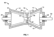
- FIG. 1 is a schematic illustration of an exemplary opposed-flow steam turbine 10 including a high pressure (hp) section 12 and an intermediate pressure (ip) section 14.
- An outer shell or casing 16 is divided axially into upper and lower half sections 13 and 15, respectively, and spans both hp section 12 and ip section 14.
- a central section 18 of shell 16 includes a high pressure steam inlet 20 and an intermediate pressure steam inlet 22.
- hp section 12 and ip section 14 are arranged in a single bearing span supported by journal bearings 26 and 28.
- a steam seal unit 30 and 32 is located inboard of each journal bearing 26 and 28, respectively.
- An annular section divider 42 extends radially inwardly from central section 18 towards a rotor shaft 60 that extends between HP section 12 and IP section 14. More specifically, divider 42 extends circumferentially around a portion of rotor shaft 60 between a first HP section nozzle 46 and a first IP section nozzle 48. Divider 42 is received in a channel 50 defined in packing casing 52. More specifically, channel 50 is a C-shaped channel that extends radially into a packing casing 52 and around an outer circumference of packing casing 52, such that a center opening of channel 50 faces radially outwardly.
- high pressure steam inlet 20 receives high pressure/high temperature steam from a steam source, for example, a power boiler (not shown). Steam is routed through HP section 12 wherein work is extracted from the steam to rotate rotor shaft 60. The steam exits HP section 12 and is returned to the boiler wherein it is reheated. Reheated steam is then routed to intermediate pressure steam inlet 22 and returned to IP section 14 at a reduced pressure than steam entering HP section 12, but at a temperature that is approximately equal to the temperature of steam entering HP section 12. Accordingly, an operating pressure within HP section 12 is higher than an operating pressure within IP section 14, such that steam within HP section 12 tends to flow towards IP section 14 through leakage paths that may develop between HP section 12 and IP section 14. One such leakage path may be defined extending through packing casing 52 within rotor shaft 60.
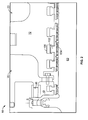
- FIG. 2 is an enlarged schematic illustration of an exemplary turbine nozzle diaphragm 70 and a packing casing 72 that may be used with turbine 10.
- nozzle diaphragm 70 is a first stage diaphragm used with high pressure turbine 12.
- packing casing 72 includes a plurality of labyrinth seal assemblies 100 that facilitate reducing leakage from HP section 12 to IP section 14 along rotor shaft 60.
- Labyrinth seal assemblies 100 include longitudinally spaced-apart rows of teeth 104 attached to a seal ring 102 that facilitate sealing against operating pressure differentials that may be present in a steam turbine such as turbine 10.
- packing casing 52 includes brush seals that may also be used to facilitate minimizing leakage through a gap defined between two components, such as leakage flowing from a higher pressure area to a lower pressure area.
- steam at higher pressure in HP section 12 tends to leak through a steam path defined between first stage nozzle diaphragm 70 and packing casing 72 to IP section 14, an area at a lower operating pressure.
- high pressure steam is admitted to HP section 12 at approximately 1800 pounds per square inch absolute (psia)
- reheat steam is admitted to IP section 14 at between approximately 300-400 psia. Accordingly, a relatively large pressure drop across packing casing 72 may cause steam to leak around packing casing 72 along rotor shaft 60 resulting in a reduction in steam turbine efficiency.
- Figure 3 is an exemplary embodiment of a labyrinth seal assembly 100 that may be used with turbine 10.
- a labyrinth seal assembly 100 that may be used with turbine 10.
- Figure 3 only a portion of rotor shaft 60 and a portion of casing 72 are illustrated.
- seal ring 102 is illustrated, several such rings could be arranged in series as shown in Figure 2.
- labyrinth seal assemblies 100 are used to facilitate sealing in other areas of turbine 10.
- Seal ring 102 includes a plurality of teeth 104 positioned in opposition to a plurality of rotor shaft circumferential projections 105 extending outward from rotor shaft 60.
- each circumferential projection 105 includes radially outer rotor surfaces 107 positioned between a plurality of radially inner rotor surfaces 109.
- a positive force may force fluid flow between the multiple restrictions formed by a clearance area 110 defined between teeth 104 and rotor shaft 60. More specifically, the combination of clearance area 110, the number, and relative sharpness, of teeth 104, the number of rotor shaft circumferential projections 105, and the operating conditions, including pressure and density, are factors that determine the amount of leakage flow. Alternately, other geometrical arrangements can also used to provide multiple or single leakage restrictions.
- each seal ring 102 is retained in a casing groove 112 defined in casing 72.
- each seal ring 102 includes a plurality of seal ring segments (not shown in Figure 3) that may be positioned within casing groove 112 to facilitate ease of assembly or disassembly of casing 72.
- a system of springs (not shown in Figure 3) induces a force that will tend to enlarge a diameter of seal ring 102 and a second system of springs (not shown in Figure 3) may be used to counter the force induced by the weight of seal ring 102.
- Each seal ring 102 includes an inner ring portion 114 having teeth 104 extending from a radially inner surface 116, and a radially outer surface 130 that facilitates controlling clearance area 110 by contacting a radial surface 118 of casing 72.
- Each seal ring 102 also includes an outer ring portion 120 that is positioned within casing groove 112.
- Outer ring portion 120 includes an inner circumferential surface 122 and an opposite radially outer surface 131.
- Inner circumferential surface 122 contacts an outer surface 126 of a casing groove shoulder 124 such that radial inward movement of seal ring 102 is limited.
- Seal ring 102 also includes a neck portion 128 extending between seal ring inner ring portion 114 and seal ring outer ring portion 120.
- Casing groove shoulder 124 interacts with seal ring neck portion 128 to axially locate each seal ring 102.
- Seal ring neck portion 128 includes a contact pressure surface 132 that contacts casing groove shoulder 124.
- One steam flow path through labyrinth seal assembly 100 is defined from high pressure region 106 to low pressure region 108 through clearance area 110 and between teeth 104 and rotor shaft surfaces 107 and 109. Steam flow is modulated as a function of radial positioning of seal ring 102. As seal ring 102 moves radially outward, the overall size of clearance area 110 increases and steam flow through clearance area 110 increases. Conversely, as seal ring 102 moves radially inward, clearance area 110 decreases and steam flow through clearance area 110 decreases.
- a second steam flow path is defined from high pressure annular space 134 to low pressure annular space 136 through casing groove 112. Steam at a higher pressure may flow from annular space 134 through an annular opening 140 defined between casing groove shoulder 124 and seal ring neck portion 128. Steam is channeled through opening 140 to a high pressure region 142 defined between casing groove shoulder outer surface 126 and seal ring outer ring portion ring circumferential surface 122 before entering a casing groove high pressure portion 144 defined by the casing 72 and seal ring outer ring portion 120. Steam exits casing groove high pressure portion 144 and enters a casing groove radially outer portion 148 defined between a casing groove radially outer surface 146 and seal ring outer portion radially outer surface 131.
- Steam may then flow to a low pressure portion 150 defined by the casing 72 and seal ring outer ring portion 120 and to a low pressure side shoulder region 152 defined between casing groove shoulder outer surface 126 and seal ring outer ring portion inner circumferential surface 122. Steam exits low pressure side shoulder region 152 through an annular opening 154 defined between casing groove shoulder 124 and seal ring neck portion 128, wherein the steam is discharged into annular space 136.
- seal ring 102 Radially outward travel of seal ring 102 is limited when seal ring outer surface 130, or any portion thereof, contacts casing radial surface 118. This position is referred to as the fully retracted position. Radially inward travel of seal ring 102 is limited when seal ring surface 122 contacts casing groove shoulder surface 126. This position is referred to as the fully inserted position, as is illustrated in Figure 3. Sufficient space to accommodate expected transient misalignments of rotor shaft 60 and casing 72, without incurring damage to teeth 104, is provided for.
- seal ring 102 At low or no load operating conditions, the weight of seal ring 102, the confining limits of casing 72, frictional forces, and the forces of a plurality of biasing spring systems (not shown on Figure 3) act on seal ring 102.
- the overall effect is that seal ring 102 is biased to a diameter as limited by the radially outward limit of travel of seal ring 102.
- Internal pressures throughout the turbine 10 are substantially proportional to load. As load and steam mass flow are each increased, local pressures increase in a substantially linear fashion. This relationship can be used to determine desired positions of seal ring 102 at pre-determined turbine operating conditions. For example, as steam flow to turbine 10 is increased, steam pressure in annular space 134 and in casing groove 112 is likewise increased. The increased steam pressure exerts a radially inward force to seal ring 102 that is substantially carried by seal ring outer surfaces 130 and 131.
- the increased steam pressure in high pressure region 106 induces increased steam flow via casing groove 112 through annular space 134, annular opening 140, shoulder region 142, casing groove high pressure portion 144, casing groove radially outer portion 148, casing groove low pressure portion 150, shoulder region 152, and annular opening 154 into annular region 136.
- the increased steam pressure in high pressure region 106 also induces increased pressures in the path defined from annular space 134 to annular space 136 via casing groove 112 as described above.
- the pressures in each subsequent region of the path are less than the regions preceding them.
- the steam pressure in casing groove low pressure portion 150 is less than the steam pressure in casing groove high pressure portion 144.
- the condition illustrated above causes steam pressure to induce an increased radially inward force to surfaces 130 and 131 as described above.
- the increased steam pressure also induces an increased radially inward force to seal ring 102 to overcome the previously discussed frictional forces and plurality of biasing spring sub-systems (not shown) forces.
- seal ring 102 and casing groove 112 are selected to facilitate optimizing the clearance 110 defined between teeth 104 and rotor shaft 60 surface for loaded, steady state operation.
- FIG. 4 is an exemplary embodiment of a sealing ring biasing spring sub-system 200.
- Sub-system 200 includes at least one threaded screw 204 inserted into packing casing 72.
- Seal ring outer ring portion 120 includes a groove 206 having pre-determined axial, radial, and arcual dimensions.
- a biasing spring-to-seal ring annular attachment groove 208 with pre-determined axial, radial, and arcual dimensions is located within seal ring outer ring groove 206.
- One end of a helical biasing spring 202 is inserted into groove 208 and spring 202 is fixedly attached to seal ring outer ring portion 120.
- biasing spring 202 is fixedly attached to threaded screw 204 such that spring 202 is positioned in casing groove 112.
- Multiple spring arrangements which include the use of a plurality of biasing springs 202, can be used to minimize the non-uniform radial force and resulting displacement of seal ring 102.
- seal ring assembly 200 is substantially similar to the operation of labyrinth seal assembly 100 described above.
- One difference between the two operations is the outward biasing force induced on seal ring 102 by biasing spring 202.
- the additional outward biasing force assists to bias seal ring 102 to a larger diameter.
- the radially outward force induced by spring 202 must be overcome prior to seal ring 102 shifting radially inward. As a result, radially inward travel of seal ring 102 is delayed until pre-determined operating conditions for turbine 10 are attained.
- FIG. 5 is an alternative exemplary embodiment sealing ring biasing spring sub-system 300.
- Sub-system 300 includes a spring passage 304 in packing casing 72.
- Seal ring outer ring portion 120 contains a groove 206 with pre-determined axial, radial and arcual dimensions.
- Biasing spring-to-seal ring annular attachment groove 208 with pre-determined axial, radial and arcual dimensions is located within seal ring outer ring groove 206.
- One end of helical biasing spring 302 is inserted into the groove 208 and is fixedly attached to seal ring outer ring portion 120.
- a spring hook device 312 is attached to a second end of biasing spring 302 which is fixedly attached to casing 72 via a groove 310 in casing groove radially outer surface.
- a cover plate 306 is coupled to outward most face of casing 72 via a plurality of fasteners 308.
- Spring 302 is suspended in spring passage 304.
- Multiple spring arrangements which include the use of a plurality of biasing springs 302 can be used to minimize the non-uniform radial force and resulting displacement of seal ring 102.
- the tensile force induced in the biasing spring 302 is based on pre-determined seal ring positions for pre-determined turbine operating conditions.
- alternative sub-system 300 is identical to sub-system 200.
- the seal assembly described herein facilitates controlling steam leakage between the rotor shaft and the packing casing. More specifically, the seal assembly will cause the clearance of seals to be large during starting, shutdown, or low load conditions, yet small during operation at medium to high loads. As a result, the degradation of operating efficiency increased turbine maintenance costs caused by seal damage can be reduced or eliminated.
- seal arrangements are described above in detail.
- the methods, apparatus and systems are not limited to the specific embodiments described herein nor to the specific seal arrangements assembled, but rather, the seal arrangements may be utilized independently and separately from other methods, apparatus and systems described herein or to assemble seal arrangements not described herein.
- other seal arrangements can also be assembled using the methods described herein.
Landscapes
- Engineering & Computer Science (AREA)
- General Engineering & Computer Science (AREA)
- Mechanical Engineering (AREA)
- Turbine Rotor Nozzle Sealing (AREA)
- Sealing Using Fluids, Sealing Without Contact, And Removal Of Oil (AREA)
Abstract
an annular groove (112) formed in a stationary casing (72), said groove extending at least partially circumferentially around the turbine;
a seal ring (102) positioned within said annular groove, said seal ring comprising a plurality of arcuate seal ring segments; and
at least one spring (202) coupled between each seal ring and said stationary casing for inducing a substially constant spring force to each of said plurality of seal ring segments.
Description
- The present invention relates generally to rotary machines and, more particularly, to a seal assembly for use in a rotary machine.
- At least some steam turbines have a defined steam path which includes, in serial-flow relationship, a steam inlet, a turbine, and a steam outlet. Steam leakage, either out of the steam path or into the steam path, from an area of higher pressure to an area of lower pressure may adversely affect an operating efficiency of the turbine. For example, steam-path leakage in the turbine between a rotating rotor shaft of the turbine and a circumferentially surrounding turbine casing, may lower the efficiency of the turbine. Additionally, steam-path leakage between a shell and the portion of the casing extending between adjacent turbines may reduce the operating efficiency of the steam turbine and over time, may lead to increased fuel costs.
- To facilitate minimizing steam-path leakage between a turbine section and a bearing, at least some known steam turbines use a packing casing that includes a plurality of labyrinth seals. Some known labyrinth seals include longitudinally spaced-apart rows of labyrinth seal teeth which are used to seal against pressure differentials that may be present in the steam turbine. Brush seals may also be used to minimize leakage through a gap defined between two components. Although brush seals generally provide a more efficient seal than labyrinth seals, at least some known steam turbines, which rely on a brush seal assembly between turbine sections and/or between a turbine section and a bearing, also use at least one labyrinth seal as a redundant backup seal for the brush seal assembly. As a result, manufacturing costs may be increased.
- The labyrinth seals are repositioned and modulated radially to adjust steam leakage flow either passively, as a function of turbine operating conditions, or, actively based on operator intervention. In general, while in the passive mode, as turbine load is increased the seals move radially inward from the retracted condition until they are fully inserted at or near full load. When fully inserted, the gap defined between the seal teeth and the turbine rotor shaft is at the minimum value and therefore any turbine transients may induce unintentional contact between the seal teeth and the rotor. The use of the active mode may reduce or eliminate contact by providing operators with a mechanism for actuating the seals as necessary in anticipation of conditions that may induce contact. Additionally, the active seal control mechanisms can be automated to achieve substantially similar results. When the turbine has been accelerated to operating speed and partially loaded, thermal gradients, vibrations and misalignments are expected to be within pre-determined ranges for the current operational conditions. Delaying the inward travel of the seals until this point in the turbine operation process minimizes the potential for inadvertent seal-to-rotor contact.
- In one aspect of the present invention, a method for assembling at least one seal assembly to a turbine having a casing extending at least partially around a rotor is provided. The method includes coupling the seal assembly to the casing such that the seal assembly extends into a fluid flow passage defined between the rotor and the casing, and coupling at least one spring between the seal assembly and the casing to bias each seal assembly.
- In another aspect, a seal assembly for a turbine assembly is provided. The seal assembly includes an annular groove formed in a stationary casing extending at least partially circumferentially around the turbine and a seal ring positioned within the annular groove. The seal ring includes a plurality of arcuate seal ring segments. At least one spring is coupled between each seal ring and the stationary casing for inducing a substantially constant spring force to each of the plurality of seal ring segments.
- In a further aspect, a rotary machine is provided. The rotary machine includes at least one rotor assembly, at least one stationary turbine casing extending at least partly circumferentially around the at least one rotor assembly such that a clearance gap is defined between the rotor assembly and the stationary turbine casing, and a plurality of seal assemblies positioned between the stationary casing and the rotor assembly to facilitate controlling the fluid flow through the clearance gap. At least one spring is positioned between each of the plurality of seal assemblies and the casing to bias each of the plurality of seal assemblies radially outward away from the rotor assembly.
- Various embodiments and aspects of the present invention will now be described in connection with the accompanying drawings, in which:
- Figure 1 is a schematic illustration of an exemplary opposed flow high pressure (hp)/intermediate pressure (ip) steam turbine;
- Figure 2 is an enlarged schematic illustration of a turbine nozzle diaphragm and a packing casing that may be used with the steam turbine shown in Figure 1;
- Figure 3 is an exemplary embodiment of a labyrinth seal assembly that may be used with the steam turbine shown in Figure 1;
- Figure 4 is an exemplary embodiment of a sealing ring biasing spring sub-system that may be used with the labyrinth seal assembly shown in Figure 3; and
- Figure 5 is an alternative exemplary embodiment of a sealing ring biasing spring sub-system that may be used with the labyrinth seal assembly shown in Figure 3.
- Figure 1 is a schematic illustration of an exemplary opposed-
flow steam turbine 10 including a high pressure (hp)section 12 and an intermediate pressure (ip)section 14. An outer shell orcasing 16 is divided axially into upper andlower half sections hp section 12 andip section 14. Acentral section 18 ofshell 16 includes a highpressure steam inlet 20 and an intermediatepressure steam inlet 22. Withincasing 16,hp section 12 andip section 14 are arranged in a single bearing span supported byjournal bearings steam seal unit - An
annular section divider 42 extends radially inwardly fromcentral section 18 towards arotor shaft 60 that extends betweenHP section 12 andIP section 14. More specifically,divider 42 extends circumferentially around a portion ofrotor shaft 60 between a firstHP section nozzle 46 and a firstIP section nozzle 48.Divider 42 is received in achannel 50 defined inpacking casing 52. More specifically,channel 50 is a C-shaped channel that extends radially into apacking casing 52 and around an outer circumference ofpacking casing 52, such that a center opening ofchannel 50 faces radially outwardly. - During operation, high
pressure steam inlet 20 receives high pressure/high temperature steam from a steam source, for example, a power boiler (not shown). Steam is routed through HPsection 12 wherein work is extracted from the steam to rotaterotor shaft 60. The steamexits HP section 12 and is returned to the boiler wherein it is reheated. Reheated steam is then routed to intermediatepressure steam inlet 22 and returned toIP section 14 at a reduced pressure than steam entering HPsection 12, but at a temperature that is approximately equal to the temperature of steam entering HPsection 12. Accordingly, an operating pressure within HPsection 12 is higher than an operating pressure withinIP section 14, such that steam within HPsection 12 tends to flow towardsIP section 14 through leakage paths that may develop between HPsection 12 andIP section 14. One such leakage path may be defined extending throughpacking casing 52 withinrotor shaft 60. - Figure 2 is an enlarged schematic illustration of an exemplary
turbine nozzle diaphragm 70 and apacking casing 72 that may be used withturbine 10. In the exemplary embodiment,nozzle diaphragm 70 is a first stage diaphragm used withhigh pressure turbine 12. Moreover, in the exemplaryembodiment packing casing 72 includes a plurality oflabyrinth seal assemblies 100 that facilitate reducing leakage from HPsection 12 toIP section 14 alongrotor shaft 60.Labyrinth seal assemblies 100 include longitudinally spaced-apart rows ofteeth 104 attached to aseal ring 102 that facilitate sealing against operating pressure differentials that may be present in a steam turbine such asturbine 10. In an alternative embodiment,packing casing 52 includes brush seals that may also be used to facilitate minimizing leakage through a gap defined between two components, such as leakage flowing from a higher pressure area to a lower pressure area. - In operation, steam at higher pressure in HP
section 12 tends to leak through a steam path defined between firststage nozzle diaphragm 70 and packingcasing 72 toIP section 14, an area at a lower operating pressure. For example, in one embodiment, high pressure steam is admitted to HPsection 12 at approximately 1800 pounds per square inch absolute (psia), and reheat steam is admitted toIP section 14 at between approximately 300-400 psia. Accordingly, a relatively large pressure drop acrosspacking casing 72 may cause steam to leak around packingcasing 72 alongrotor shaft 60 resulting in a reduction in steam turbine efficiency. - Figure 3 is an exemplary embodiment of a
labyrinth seal assembly 100 that may be used withturbine 10. In Figure 3 only a portion ofrotor shaft 60 and a portion ofcasing 72 are illustrated. Furthermore, although only asingle seal ring 102 is illustrated, several such rings could be arranged in series as shown in Figure 2. In alternative embodiments,labyrinth seal assemblies 100 are used to facilitate sealing in other areas ofturbine 10. -
Seal ring 102 includes a plurality ofteeth 104 positioned in opposition to a plurality of rotor shaftcircumferential projections 105 extending outward fromrotor shaft 60. In the exemplary embodiment, eachcircumferential projection 105 includes radiallyouter rotor surfaces 107 positioned between a plurality of radiallyinner rotor surfaces 109. As explained above, a positive force may force fluid flow between the multiple restrictions formed by aclearance area 110 defined betweenteeth 104 androtor shaft 60. More specifically, the combination ofclearance area 110, the number, and relative sharpness, ofteeth 104, the number of rotor shaftcircumferential projections 105, and the operating conditions, including pressure and density, are factors that determine the amount of leakage flow. Alternately, other geometrical arrangements can also used to provide multiple or single leakage restrictions. - Each
seal ring 102 is retained in acasing groove 112 defined incasing 72. In one embodiment, eachseal ring 102 includes a plurality of seal ring segments (not shown in Figure 3) that may be positioned withincasing groove 112 to facilitate ease of assembly or disassembly ofcasing 72. In the exemplary embodiment, a system of springs (not shown in Figure 3) induces a force that will tend to enlarge a diameter ofseal ring 102 and a second system of springs (not shown in Figure 3) may be used to counter the force induced by the weight ofseal ring 102. - Each
seal ring 102 includes aninner ring portion 114 havingteeth 104 extending from a radiallyinner surface 116, and a radiallyouter surface 130 that facilitates controllingclearance area 110 by contacting aradial surface 118 ofcasing 72. Eachseal ring 102 also includes anouter ring portion 120 that is positioned withincasing groove 112.Outer ring portion 120 includes an innercircumferential surface 122 and an opposite radially outer surface 131. Innercircumferential surface 122 contacts anouter surface 126 of acasing groove shoulder 124 such that radial inward movement ofseal ring 102 is limited.Seal ring 102 also includes a neck portion 128 extending between seal ringinner ring portion 114 and seal ringouter ring portion 120.Casing groove shoulder 124 interacts with seal ring neck portion 128 to axially locate eachseal ring 102. Seal ring neck portion 128 includes acontact pressure surface 132 that contacts casinggroove shoulder 124. - One steam flow path through
labyrinth seal assembly 100 is defined fromhigh pressure region 106 tolow pressure region 108 throughclearance area 110 and betweenteeth 104 and rotor shaft surfaces 107 and 109. Steam flow is modulated as a function of radial positioning ofseal ring 102. Asseal ring 102 moves radially outward, the overall size ofclearance area 110 increases and steam flow throughclearance area 110 increases. Conversely, asseal ring 102 moves radially inward,clearance area 110 decreases and steam flow throughclearance area 110 decreases. - A second steam flow path is defined from high pressure
annular space 134 to low pressureannular space 136 throughcasing groove 112. Steam at a higher pressure may flow fromannular space 134 through anannular opening 140 defined betweencasing groove shoulder 124 and seal ring neck portion 128. Steam is channeled throughopening 140 to ahigh pressure region 142 defined between casing groove shoulderouter surface 126 and seal ring outer ring portion ringcircumferential surface 122 before entering a casing groovehigh pressure portion 144 defined by thecasing 72 and seal ringouter ring portion 120. Steam exits casing groovehigh pressure portion 144 and enters a casing groove radiallyouter portion 148 defined between a casing groove radiallyouter surface 146 and seal ring outer portion radially outer surface 131. Steam may then flow to alow pressure portion 150 defined by thecasing 72 and seal ringouter ring portion 120 and to a low pressureside shoulder region 152 defined between casing groove shoulderouter surface 126 and seal ring outer ring portion innercircumferential surface 122. Steam exits low pressureside shoulder region 152 through anannular opening 154 defined betweencasing groove shoulder 124 and seal ring neck portion 128, wherein the steam is discharged intoannular space 136. - Radially outward travel of
seal ring 102 is limited when seal ringouter surface 130, or any portion thereof, contacts casingradial surface 118. This position is referred to as the fully retracted position. Radially inward travel ofseal ring 102 is limited whenseal ring surface 122 contacts casinggroove shoulder surface 126. This position is referred to as the fully inserted position, as is illustrated in Figure 3. Sufficient space to accommodate expected transient misalignments ofrotor shaft 60 andcasing 72, without incurring damage toteeth 104, is provided for. - At low or no load operating conditions, the weight of
seal ring 102, the confining limits ofcasing 72, frictional forces, and the forces of a plurality of biasing spring systems (not shown on Figure 3) act onseal ring 102. The overall effect is thatseal ring 102 is biased to a diameter as limited by the radially outward limit of travel ofseal ring 102. - Internal pressures throughout the
turbine 10 are substantially proportional to load. As load and steam mass flow are each increased, local pressures increase in a substantially linear fashion. This relationship can be used to determine desired positions ofseal ring 102 at pre-determined turbine operating conditions. For example, as steam flow toturbine 10 is increased, steam pressure inannular space 134 and incasing groove 112 is likewise increased. The increased steam pressure exerts a radially inward force toseal ring 102 that is substantially carried by seal ringouter surfaces 130 and 131. - The increased steam pressure in
high pressure region 106 induces increased steam flow viacasing groove 112 throughannular space 134,annular opening 140,shoulder region 142, casing groovehigh pressure portion 144, casing groove radiallyouter portion 148, casing groovelow pressure portion 150,shoulder region 152, andannular opening 154 intoannular region 136. The increased steam pressure inhigh pressure region 106 also induces increased pressures in the path defined fromannular space 134 toannular space 136 viacasing groove 112 as described above. The pressures in each subsequent region of the path are less than the regions preceding them. For example, the steam pressure in casing groovelow pressure portion 150 is less than the steam pressure in casing groovehigh pressure portion 144. This pressure differential induces an increased force to the right on seal ringinner ring portion 114, seal ring neck portion 128 and seal ringouter ring portion 120. The increased forces on these surfaces causesseal ring 102 to move axially toward thelow pressure region 108 until seal ring neckcontact pressure surface 132 contacts casinggroove shoulder 124. When fully inserted steam flow from high pressureannular space 134 to low pressureannular space 136 viacasing groove 112 is substantially prevented byseal ring 102. - The condition illustrated above causes steam pressure to induce an increased radially inward force to
surfaces 130 and 131 as described above. The increased steam pressure also induces an increased radially inward force toseal ring 102 to overcome the previously discussed frictional forces and plurality of biasing spring sub-systems (not shown) forces. - The dimensions of
seal ring 102 andcasing groove 112 are selected to facilitate optimizing theclearance 110 defined betweenteeth 104 androtor shaft 60 surface for loaded, steady state operation. - Figure 4 is an exemplary embodiment of a sealing ring biasing
spring sub-system 200.Sub-system 200 includes at least one threadedscrew 204 inserted into packingcasing 72. Seal ringouter ring portion 120 includes agroove 206 having pre-determined axial, radial, and arcual dimensions. A biasing spring-to-seal ringannular attachment groove 208 with pre-determined axial, radial, and arcual dimensions is located within seal ringouter ring groove 206. One end of ahelical biasing spring 202 is inserted intogroove 208 andspring 202 is fixedly attached to seal ringouter ring portion 120. A second end of biasingspring 202 is fixedly attached to threadedscrew 204 such thatspring 202 is positioned incasing groove 112. Multiple spring arrangements, which include the use of a plurality of biasingsprings 202, can be used to minimize the non-uniform radial force and resulting displacement ofseal ring 102. - The operation of
seal ring assembly 200 is substantially similar to the operation oflabyrinth seal assembly 100 described above. One difference between the two operations is the outward biasing force induced onseal ring 102 by biasingspring 202. The additional outward biasing force assists to biasseal ring 102 to a larger diameter. As turbine load and steam pressures are increased, the radially outward force induced byspring 202 must be overcome prior toseal ring 102 shifting radially inward. As a result, radially inward travel ofseal ring 102 is delayed until pre-determined operating conditions forturbine 10 are attained. - Figure 5 is an alternative exemplary embodiment sealing ring biasing
spring sub-system 300.Sub-system 300 includes aspring passage 304 in packingcasing 72. Seal ringouter ring portion 120 contains agroove 206 with pre-determined axial, radial and arcual dimensions. Biasing spring-to-seal ringannular attachment groove 208 with pre-determined axial, radial and arcual dimensions is located within seal ringouter ring groove 206. One end ofhelical biasing spring 302 is inserted into thegroove 208 and is fixedly attached to seal ringouter ring portion 120. Aspring hook device 312 is attached to a second end of biasingspring 302 which is fixedly attached to casing 72 via agroove 310 in casing groove radially outer surface. Acover plate 306 is coupled to outward most face of casing 72 via a plurality offasteners 308.Spring 302 is suspended inspring passage 304. Multiple spring arrangements which include the use of a plurality of biasingsprings 302 can be used to minimize the non-uniform radial force and resulting displacement ofseal ring 102. The tensile force induced in thebiasing spring 302 is based on pre-determined seal ring positions for pre-determined turbine operating conditions. - The operation of
alternative sub-system 300 is identical tosub-system 200. - The seal assembly described herein facilitates controlling steam leakage between the rotor shaft and the packing casing. More specifically, the seal assembly will cause the clearance of seals to be large during starting, shutdown, or low load conditions, yet small during operation at medium to high loads. As a result, the degradation of operating efficiency increased turbine maintenance costs caused by seal damage can be reduced or eliminated.
- Although the methods and systems described and/or illustrated herein are described and/or illustrated with respect to a rotating machine, and more specifically a steam turbine, practice of the methods and systems described and/or illustrated herein is not limited to steam turbines nor to rotating machines generally. Rather, the methods and systems described and/or illustrated herein are applicable to assembling any seal arrangement on any machine.
- Exemplary embodiments of seal arrangements are described above in detail. The methods, apparatus and systems are not limited to the specific embodiments described herein nor to the specific seal arrangements assembled, but rather, the seal arrangements may be utilized independently and separately from other methods, apparatus and systems described herein or to assemble seal arrangements not described herein. For example, other seal arrangements can also be assembled using the methods described herein.
- While the invention has been described in terms of various specific embodiments, those skilled in the art will recognize that the invention can be practiced with modification within the spirit and scope of the claims.
-
- 10
- Steam turbine
- 12
- High pressure (HP) section
- 13
- Upper half section
- 14
- Intermediate pressure (IP) section
- 15
- Lower half section
- 16
- Outer shell or casing
- 18
- Central section
- 20
- High pressure steam inlet
- 22
- Intermediate pressure steam inlet
- 26
- Journal bearings
- 28
- Journal bearings
- 30
- Steam seal unit
- 32
- Steam seal unit
- 42
- Annular section divider
- 46
- First HP section nozzle
- 48
- First IP section nozzle
- 50
- Channel
- 52
- Packing casing
- 60
- Rotor shaft
- 70
- First stage nozzle diaphragm
- 72
- Packing casing
- 100
- Labyrinth seal assembly
- 102
- Seal ring
- 104
- Teeth
- 105
- Rotor shaft circumferential projections
- 106
- High pressure region
- 107
- Radially outer rotor shaft surfaces
- 108
- Low pressure region
- 109
- Radially inner rotor shaft surfaces
- 110
- Clearance area
- 112
- Casing groove
- 114
- Ring inner ring portion
- 116
- Radially inner surface
- 118
- Casing radial surface
- 120
- Ring outer ring portion
- 122
- Seal ring inner circumferential surface
- 124
- Casing groove shoulder
- 126
- Casing groove shoulder surface
- 128
- Seal ring neck portion
- 130
- Seal ring outer surface
- 131
- Radially outer surface
- 132
- Neck contact pressure surface
- 134
- High pressure annular space
- 136
- Low pressure annular space
- 140
- Annular opening
- 142
- High pressure side shoulder region
- 144
- Groove high pressure portion
- 146
- Groove radially outer surface
- 148
- Groove radially outer portion
- 150
- Groove low pressure portion
- 152
- Pressure side shoulder region
- 154
- Annular opening
- 200
- Sealing ring biasing spring sub-system
- 202
- Biasing spring
- 204
- Threaded screw
- 206
- Ring outer ring groove
- 208
- Ring annular attachment groove
- 300
- Spring sub-system
- 302
- Biasing springs
- 304
- Spring passage
- 306
- Cover plate
- 308
- Fasteners
- 310
- Groove
- 312
- Spring hook device
Claims (10)
- A seal assembly (100) for a turbine assembly (10), said seal assembly comprising:an annular groove (112) formed in a stationary casing (72), said groove extending at least partially circumferentially around the turbine;a seal ring (102) positioned within said annular groove, said seal ring comprising a plurality of arcuate seal ring segments; andat least one spring (202) coupled between each said seal ring and said stationary casing for inducing a substantially constant spring force to each of said plurality of seal ring segments.
- A seal assembly (100) in accordance with Claim 1 wherein said annular groove (112) is defined at least partially by a pair of opposed shoulders (124).
- A seal assembly (100) in accordance with Claim 1 or Claim 2 wherein said at least one spring (202) facilitates increasing an amount of a clearance space (110) defined between the turbine (10) and said stationary casing (72).
- A seal assembly (100) in accordance with any preceding Claim wherein each of said plurality of arcuate seal ring segments comprises:a radially inner sealing surface (116) comprising a plurality of sealing teeth (104);a radially outer ring portion (120) sized to be received in said annular groove, said outer ring portion comprises a radially outer surface (131) and a radially inner surface (130); anda neck portion (128) extending between said radially inner sealing surface and said radially outer ring portion.
- A seal assembly (100) for a turbine (10) in accordance with any preceding Claim wherein said at least one spring (202) comprises at least one helical spring configured to bias said seal assembly away from the turbine.
- A rotary machine comprising:at least one rotor assembly (60);at least one stationary turbine casing (72) extending at least partly circumferentially around said at least one rotor assembly such that a clearance gap (110) is defined between said at least one rotor assembly and said at least one stationary turbine casing;a plurality of seal assemblies (100) positioned between said at least one stationary casing and said at least one rotor assembly to facilitate controlling said fluid flow through said clearance gap; andat least one spring (202) positioned between each of said plurality of seal assemblies and said casing to bias each of said plurality of seal assemblies radially outward away from said at least one rotor assembly.
- A rotary machine in accordance with Claim 6 wherein said at least one stationary casing (72) comprises at least one annular groove (112) defined therein.
- A rotary machine in accordance with Claim 7 wherein each said at least one groove (112) is defined at least partially by a pair of opposed shoulders (124).
- A rotary machine in accordance with any of Claims 6 to 8wherein each of said plurality of seal assemblies (100) comprises a plurality of arcuate seal segments sized to be received within said at least one of said annular grooves (112).
- A rotary machine in accordance with any of Claims 6 to 9 wherein each of said plurality of seal assemblies (100) comprises a radially outer surface (131) and a radially inner surface (130) extending from said radially outer ring surface (120).
Applications Claiming Priority (1)
| Application Number | Priority Date | Filing Date | Title |
|---|---|---|---|
| US11/219,268 US7344357B2 (en) | 2005-09-02 | 2005-09-02 | Methods and apparatus for assembling a rotary machine |
Publications (2)
| Publication Number | Publication Date |
|---|---|
| EP1760270A2 true EP1760270A2 (en) | 2007-03-07 |
| EP1760270A3 EP1760270A3 (en) | 2010-05-05 |
Family
ID=37490945
Family Applications (1)
| Application Number | Title | Priority Date | Filing Date |
|---|---|---|---|
| EP06254489A Withdrawn EP1760270A3 (en) | 2005-09-02 | 2006-08-29 | Seal assembly |
Country Status (5)
| Country | Link |
|---|---|
| US (1) | US7344357B2 (en) |
| EP (1) | EP1760270A3 (en) |
| JP (1) | JP2007071203A (en) |
| KR (1) | KR20070026217A (en) |
| CN (1) | CN1924301A (en) |
Cited By (3)
| Publication number | Priority date | Publication date | Assignee | Title |
|---|---|---|---|---|
| DE102007023381A1 (en) * | 2007-05-18 | 2008-11-20 | Mtu Aero Engines Gmbh | Device for preventing piercing of flame or explosion front from chamber to another chamber in area of movable elements connecting both chambers, has brush seal for achieving pressure and heat-resistant |
| EP3232010A4 (en) * | 2014-12-24 | 2018-01-10 | Mitsubishi Heavy Industries Compressor Corporation | Nozzle structure and rotary machine |
| CN112335105A (en) * | 2018-06-25 | 2021-02-05 | 麦格纳国际公司 | battery frame |
Families Citing this family (33)
| Publication number | Priority date | Publication date | Assignee | Title |
|---|---|---|---|---|
| US7059294B2 (en) * | 2004-05-27 | 2006-06-13 | Wright Innovations, Llc | Orbital engine |
| US8151759B2 (en) * | 2006-08-24 | 2012-04-10 | Wright Innovations, Llc | Orbital engine |
| KR100878460B1 (en) * | 2007-07-06 | 2009-01-13 | 한국과학기술연구원 | Labyrinth seal |
| US8205889B2 (en) * | 2007-11-27 | 2012-06-26 | General Electric Company | Methods and apparatus to facilitate sealing in rotary machines |
| US7909335B2 (en) * | 2008-02-04 | 2011-03-22 | General Electric Company | Retractable compliant plate seals |
| WO2013191718A1 (en) * | 2012-06-19 | 2013-12-27 | Stein Seal Company | Segmented intershaft seal assembly |
| US8820752B2 (en) | 2008-09-15 | 2014-09-02 | Stein Seal Company | Intershaft seal with centrifugal compensation |
| US9004495B2 (en) * | 2008-09-15 | 2015-04-14 | Stein Seal Company | Segmented intershaft seal assembly |
| JP5558138B2 (en) * | 2010-02-25 | 2014-07-23 | 三菱重工業株式会社 | Turbine |
| US8434766B2 (en) | 2010-08-18 | 2013-05-07 | General Electric Company | Turbine engine seals |
| US8454023B2 (en) * | 2011-05-10 | 2013-06-04 | General Electric Company | Retractable seal system |
| US8342009B2 (en) | 2011-05-10 | 2013-01-01 | General Electric Company | Method for determining steampath efficiency of a steam turbine section with internal leakage |
| KR101906949B1 (en) | 2012-02-29 | 2018-10-11 | 한화에어로스페이스 주식회사 | A turbine seal assembly and a turbine apparatus comprising the same |
| JP2013177866A (en) * | 2012-02-29 | 2013-09-09 | Hitachi Ltd | Turbomachine |
| US10215044B2 (en) * | 2014-08-08 | 2019-02-26 | Siemens Energy, Inc. | Interstage seal housing optimization system in a gas turbine engine |
| WO2016179608A2 (en) * | 2016-04-29 | 2016-11-10 | Stein Seal Company | Intershaft seal with asymmetric sealing ring |
| US10598035B2 (en) * | 2016-05-27 | 2020-03-24 | General Electric Company | Intershaft sealing systems for gas turbine engines and methods for assembling the same |
| CN111720175B (en) * | 2020-06-23 | 2022-04-19 | 中国科学院工程热物理研究所 | Impeller machinery movable vane top seal structure |
| CN113090342B (en) * | 2021-04-08 | 2023-01-13 | 沈阳航空航天大学 | Active clearance control labyrinth seal structure based on memory alloy wire |
| US11821320B2 (en) | 2021-06-04 | 2023-11-21 | General Electric Company | Turbine engine with a rotor seal assembly |
| US12270304B2 (en) | 2021-07-26 | 2025-04-08 | General Electric Company | Turbine engine with a floating seal assembly |
| US12006829B1 (en) | 2023-02-16 | 2024-06-11 | General Electric Company | Seal member support system for a gas turbine engine |
| US12486779B2 (en) | 2023-03-08 | 2025-12-02 | General Electric Company | Seal support assembly for a turbine engine |
| US12372002B2 (en) | 2023-03-24 | 2025-07-29 | General Electric Company | Seal support assembly for a turbine engine |
| US12241375B2 (en) | 2023-03-24 | 2025-03-04 | General Electric Company | Seal support assembly for a turbine engine |
| US12416243B2 (en) | 2023-03-24 | 2025-09-16 | General Electric Company | Seal support assembly for a turbine engine |
| US12215587B2 (en) | 2023-03-24 | 2025-02-04 | General Electric Company | Seal support assembly for a turbine engine |
| US12421861B2 (en) | 2023-03-24 | 2025-09-23 | General Electric Company | Seal support assembly for a turbine engine |
| US12595745B2 (en) | 2023-03-24 | 2026-04-07 | General Electric Company | Seal support assembly for a turbine engine |
| US12116896B1 (en) | 2023-03-24 | 2024-10-15 | General Electric Company | Seal support assembly for a turbine engine |
| US12215588B2 (en) | 2023-03-27 | 2025-02-04 | General Electric Company | Seal assembly for a gas turbine engine |
| US12326089B2 (en) | 2023-04-24 | 2025-06-10 | General Electric Company | Seal assembly for a gas turbine engine |
| US12584415B2 (en) | 2024-05-03 | 2026-03-24 | General Electric Company | Turbine engine seal for turbine engines |
Family Cites Families (19)
| Publication number | Priority date | Publication date | Assignee | Title |
|---|---|---|---|---|
| JPS54142453A (en) * | 1978-04-28 | 1979-11-06 | Toshiba Corp | Axial seal body of rotation body |
| JPS61152906A (en) * | 1984-12-27 | 1986-07-11 | Toshiba Corp | Seal part gap regulating device for turbine |
| JP2633543B2 (en) * | 1987-01-27 | 1997-07-23 | 株式会社東芝 | Turbine speed control device |
| JPS63186904U (en) * | 1987-05-22 | 1988-11-30 | ||
| US5002288A (en) * | 1988-10-13 | 1991-03-26 | General Electric Company | Positive variable clearance labyrinth seal |
| DE4032683C3 (en) * | 1990-10-15 | 1996-06-13 | Santrade Ltd | Device for forming drops |
| US5374068A (en) * | 1991-05-07 | 1994-12-20 | General Electric Co. | Method for providing uniform radial clearance of labyrinth seals between rotating and stationary components |
| US5603510A (en) * | 1991-06-13 | 1997-02-18 | Sanders; William P. | Variable clearance seal assembly |
| DE19616243A1 (en) * | 1996-04-15 | 1997-10-16 | Abb Kraftwerke Berlin Gmbh | Turboset bearing ring |
| US5709388A (en) * | 1996-09-27 | 1998-01-20 | General Electric Co. | Variable clearance packing ring with guide for preventing circumferential displacement |
| US6022027A (en) * | 1997-12-18 | 2000-02-08 | General Electric Co. | Variable clearance packing ring with clips for preventing circumferential displacement |
| US6065754A (en) * | 1998-04-15 | 2000-05-23 | General Electric Co. | Uniform clearance, temperature responsive, variable packing ring |
| JP2002285802A (en) * | 2001-03-26 | 2002-10-03 | Toshiba Corp | Labyrinth sealing device for rotating machinery |
| US6695316B2 (en) * | 2001-09-21 | 2004-02-24 | General Electric Company | Apparatus and methods for supporting a retractable packing ring |
| JP3702212B2 (en) * | 2001-09-28 | 2005-10-05 | 三菱重工業株式会社 | Shaft seal mechanism and turbine |
| US6715766B2 (en) * | 2001-10-30 | 2004-04-06 | General Electric Company | Steam feed hole for retractable packing segments in rotary machines |
| US6786487B2 (en) * | 2001-12-05 | 2004-09-07 | General Electric Company | Actuated brush seal |
| US6651986B2 (en) * | 2002-01-29 | 2003-11-25 | General Electric Company | Retractable packing ring lower half segment retaining key and method for retaining retractable packing ring lower half segment |
| EP1643172B1 (en) * | 2004-09-30 | 2008-06-18 | General Electric Company | Compliant seal and system and method thereof |
-
2005
- 2005-09-02 US US11/219,268 patent/US7344357B2/en not_active Expired - Fee Related
-
2006
- 2006-08-29 EP EP06254489A patent/EP1760270A3/en not_active Withdrawn
- 2006-08-31 KR KR1020060083850A patent/KR20070026217A/en not_active Withdrawn
- 2006-09-01 JP JP2006237905A patent/JP2007071203A/en active Pending
- 2006-09-04 CN CNA2006101290435A patent/CN1924301A/en active Pending
Cited By (5)
| Publication number | Priority date | Publication date | Assignee | Title |
|---|---|---|---|---|
| DE102007023381A1 (en) * | 2007-05-18 | 2008-11-20 | Mtu Aero Engines Gmbh | Device for preventing piercing of flame or explosion front from chamber to another chamber in area of movable elements connecting both chambers, has brush seal for achieving pressure and heat-resistant |
| DE102007023381B4 (en) * | 2007-05-18 | 2012-12-06 | Mtu Aero Engines Gmbh | Device for preventing the penetration of a flame and / or explosion front |
| EP3232010A4 (en) * | 2014-12-24 | 2018-01-10 | Mitsubishi Heavy Industries Compressor Corporation | Nozzle structure and rotary machine |
| CN112335105A (en) * | 2018-06-25 | 2021-02-05 | 麦格纳国际公司 | battery frame |
| CN112335105B (en) * | 2018-06-25 | 2023-12-26 | 麦格纳国际公司 | battery frame |
Also Published As
| Publication number | Publication date |
|---|---|
| US20070053772A1 (en) | 2007-03-08 |
| JP2007071203A (en) | 2007-03-22 |
| US7344357B2 (en) | 2008-03-18 |
| CN1924301A (en) | 2007-03-07 |
| EP1760270A3 (en) | 2010-05-05 |
| KR20070026217A (en) | 2007-03-08 |
Similar Documents
| Publication | Publication Date | Title |
|---|---|---|
| US7344357B2 (en) | Methods and apparatus for assembling a rotary machine | |
| EP1860356B1 (en) | Method and apparatus for variable clearance packing | |
| US8540479B2 (en) | Active retractable seal for turbo machinery and related method | |
| KR20070108822A (en) | Tension Spring Actuator for Variable Positive Positive Packing for Steam Turbines | |
| EP2427676B1 (en) | Sealing apparatus and method for steam turbines | |
| GB2439635A (en) | A variable clearance packing ring for a seal | |
| EP3002487B1 (en) | Sealing system | |
| US9829007B2 (en) | Turbine sealing system | |
| US20250230754A1 (en) | Seal assembly for a rotary machine | |
| CN108350754A (en) | Rotating machine and method of controlling the rotating machine | |
| EP1790886B1 (en) | A variable clearance packing ring arrangement | |
| US6761530B1 (en) | Method and apparatus to facilitate reducing turbine packing leakage losses | |
| US7780407B2 (en) | Rotary machines and methods of assembling | |
| US20130170965A1 (en) | Compliant plate seal for use with rotating machines and methods of assembling a rotating machine | |
| US6571470B1 (en) | Method of retrofitting seals in a gas turbine | |
| US20070040335A1 (en) | Axially adjustable sealing ring | |
| US20040156722A1 (en) | Method and apparatus to facilitate reducing steam leakage | |
| GB2408548A (en) | Finned seals for turbomachinery | |
| US7540708B2 (en) | Methods and apparatus to facilitate sealing in a turbine | |
| US20240368995A1 (en) | Rotor and turbomachine comprising the rotor | |
| JPH0437310B2 (en) | ||
| US20140205440A1 (en) | Compliant plate seals for rotary machines | |
| EP4673670A1 (en) | Piston rings for steam turbine valves and piston ring assemblies | |
| EP3396114A1 (en) | Turbomachinery and corresponding method of operating |
Legal Events
| Date | Code | Title | Description |
|---|---|---|---|
| PUAI | Public reference made under article 153(3) epc to a published international application that has entered the european phase |
Free format text: ORIGINAL CODE: 0009012 |
|
| AK | Designated contracting states |
Kind code of ref document: A2 Designated state(s): AT BE BG CH CY CZ DE DK EE ES FI FR GB GR HU IE IS IT LI LT LU LV MC NL PL PT RO SE SI SK TR |
|
| AX | Request for extension of the european patent |
Extension state: AL BA HR MK YU |
|
| RIN1 | Information on inventor provided before grant (corrected) |
Inventor name: MORTZHEIM, JASON PAUL Inventor name: KELLY, MARK E. Inventor name: RIVAS, FLOR DEL CARMEN Inventor name: COUTURE, BERNARD ARTHUR, JR. |
|
| PUAL | Search report despatched |
Free format text: ORIGINAL CODE: 0009013 |
|
| AK | Designated contracting states |
Kind code of ref document: A3 Designated state(s): AT BE BG CH CY CZ DE DK EE ES FI FR GB GR HU IE IS IT LI LT LU LV MC NL PL PT RO SE SI SK TR |
|
| AX | Request for extension of the european patent |
Extension state: AL BA HR MK RS |
|
| 17P | Request for examination filed |
Effective date: 20101105 |
|
| AKX | Designation fees paid |
Designated state(s): CH DE FR GB IT LI |
|
| 17Q | First examination report despatched |
Effective date: 20110114 |
|
| STAA | Information on the status of an ep patent application or granted ep patent |
Free format text: STATUS: THE APPLICATION IS DEEMED TO BE WITHDRAWN |
|
| 18D | Application deemed to be withdrawn |
Effective date: 20111212 |