EP1760263A2 - Stator vane profile optimization - Google Patents
Stator vane profile optimization Download PDFInfo
- Publication number
- EP1760263A2 EP1760263A2 EP06254333A EP06254333A EP1760263A2 EP 1760263 A2 EP1760263 A2 EP 1760263A2 EP 06254333 A EP06254333 A EP 06254333A EP 06254333 A EP06254333 A EP 06254333A EP 1760263 A2 EP1760263 A2 EP 1760263A2
- Authority
- EP
- European Patent Office
- Prior art keywords
- airfoil
- profile
- accordance
- compressor
- base
- Prior art date
- Legal status (The legal status is an assumption and is not a legal conclusion. Google has not performed a legal analysis and makes no representation as to the accuracy of the status listed.)
- Withdrawn
Links
Images

Classifications
-
- F—MECHANICAL ENGINEERING; LIGHTING; HEATING; WEAPONS; BLASTING
- F01—MACHINES OR ENGINES IN GENERAL; ENGINE PLANTS IN GENERAL; STEAM ENGINES
- F01D—NON-POSITIVE DISPLACEMENT MACHINES OR ENGINES, e.g. STEAM TURBINES
- F01D9/00—Stators
-
- F—MECHANICAL ENGINEERING; LIGHTING; HEATING; WEAPONS; BLASTING
- F01—MACHINES OR ENGINES IN GENERAL; ENGINE PLANTS IN GENERAL; STEAM ENGINES
- F01D—NON-POSITIVE DISPLACEMENT MACHINES OR ENGINES, e.g. STEAM TURBINES
- F01D5/00—Blades; Blade-carrying members; Heating, heat-insulating, cooling or antivibration means on the blades or the members
- F01D5/12—Blades
- F01D5/14—Form or construction
- F01D5/141—Shape, i.e. outer, aerodynamic form
-
- F—MECHANICAL ENGINEERING; LIGHTING; HEATING; WEAPONS; BLASTING
- F01—MACHINES OR ENGINES IN GENERAL; ENGINE PLANTS IN GENERAL; STEAM ENGINES
- F01D—NON-POSITIVE DISPLACEMENT MACHINES OR ENGINES, e.g. STEAM TURBINES
- F01D5/00—Blades; Blade-carrying members; Heating, heat-insulating, cooling or antivibration means on the blades or the members
- F01D5/12—Blades
-
- F—MECHANICAL ENGINEERING; LIGHTING; HEATING; WEAPONS; BLASTING
- F01—MACHINES OR ENGINES IN GENERAL; ENGINE PLANTS IN GENERAL; STEAM ENGINES
- F01D—NON-POSITIVE DISPLACEMENT MACHINES OR ENGINES, e.g. STEAM TURBINES
- F01D9/00—Stators
- F01D9/02—Nozzles; Nozzle boxes; Stator blades; Guide conduits, e.g. individual nozzles
-
- F—MECHANICAL ENGINEERING; LIGHTING; HEATING; WEAPONS; BLASTING
- F04—POSITIVE - DISPLACEMENT MACHINES FOR LIQUIDS; PUMPS FOR LIQUIDS OR ELASTIC FLUIDS
- F04D—NON-POSITIVE-DISPLACEMENT PUMPS
- F04D29/00—Details, component parts, or accessories
- F04D29/40—Casings; Connections of working fluid
- F04D29/52—Casings; Connections of working fluid for axial pumps
- F04D29/54—Fluid-guiding means, e.g. diffusers
- F04D29/541—Specially adapted for elastic fluid pumps
- F04D29/542—Bladed diffusers
-
- F—MECHANICAL ENGINEERING; LIGHTING; HEATING; WEAPONS; BLASTING
- F05—INDEXING SCHEMES RELATING TO ENGINES OR PUMPS IN VARIOUS SUBCLASSES OF CLASSES F01-F04
- F05D—INDEXING SCHEME FOR ASPECTS RELATING TO NON-POSITIVE-DISPLACEMENT MACHINES OR ENGINES, GAS-TURBINES OR JET-PROPULSION PLANTS
- F05D2240/00—Components
- F05D2240/10—Stators
- F05D2240/12—Fluid guiding means, e.g. vanes
-
- F—MECHANICAL ENGINEERING; LIGHTING; HEATING; WEAPONS; BLASTING
- F05—INDEXING SCHEMES RELATING TO ENGINES OR PUMPS IN VARIOUS SUBCLASSES OF CLASSES F01-F04
- F05D—INDEXING SCHEME FOR ASPECTS RELATING TO NON-POSITIVE-DISPLACEMENT MACHINES OR ENGINES, GAS-TURBINES OR JET-PROPULSION PLANTS
- F05D2250/00—Geometry
- F05D2250/70—Shape
- F05D2250/74—Shape given by a set or table of xyz-coordinates
-
- Y—GENERAL TAGGING OF NEW TECHNOLOGICAL DEVELOPMENTS; GENERAL TAGGING OF CROSS-SECTIONAL TECHNOLOGIES SPANNING OVER SEVERAL SECTIONS OF THE IPC; TECHNICAL SUBJECTS COVERED BY FORMER USPC CROSS-REFERENCE ART COLLECTIONS [XRACs] AND DIGESTS
- Y10—TECHNICAL SUBJECTS COVERED BY FORMER USPC
- Y10S—TECHNICAL SUBJECTS COVERED BY FORMER USPC CROSS-REFERENCE ART COLLECTIONS [XRACs] AND DIGESTS
- Y10S416/00—Fluid reaction surfaces, i.e. impellers
- Y10S416/02—Formulas of curves
Definitions
- the present invention relates generally to stator vanes for gas turbines and, more particularly, to a novel and improved profile for a ninth stage compressor stator vane.
- Airfoil profiles for gas turbines have been proposed to provide improved performance, lower operating temperatures, increased creep margin and extended life in relation to conventional airfoils. See, for example, U.S. Patent No. 5,980,209 describing an enhanced turbine blade airfoil profile.
- Advanced materials and new steam cooling systems now permit gas turbines to operate at, and accommodate, much higher operating temperatures, mechanical loading, and pressures than is capable in at least some known turbine engines.
- many system requirements must be met for each stage of each compressor used with the turbine engines in order to meet design goals including overall improved efficiency and airfoil loading.
- the airfoils of the stator vanes positioned within the compressors must meet the thermal and mechanical operating requirements for each particular stage.
- an airfoil for a stator vane has an uncoated profile substantially in accordance with Cartesian coordinate values of X, Y and Z set forth in Table I carried only to four decimal places wherein Z is a distance from a platform on which the airfoil is mounted and X and Y are coordinates defining the profile at each distance Z from the platform.
- a compressor comprising at least one row of stator vanes.
- Each of the stator vanes comprises a base and an airfoil extending therefrom.
- At least one of the airfoils has an airfoil shape.
- the airfoil shape has a nominal profile substantially in accordance with Cartesian coordinate values of X, Y and Z set forth in Table I carried only to three decimal places wherein Z is a distance from a platform on which the airfoil is mounted and X and Y ace coordinates defining the profile at each distance Z from the platform.
- a stator assembly in a further aspect of the invention, includes at least one stator vane including a base and an airfoil extending from the base.
- the airfoil has an uncoated profile substantially in accordance with Cartesian coordinate values of X, Y and Z set forth in Table I carried only to three decimal places wherein Z is a distance from a platform on which the airfoil is mounted and X and Y are coordinates defining the profile at each distance Z from the base.
- the profile is scalable by a predetermined constant n and manufacturable to a predetermined manufacturing tolerance.
- FIG. 1 is a schematic illustration of an exemplary gas turbine engine 10 coupled to an electric generator 16.
- gas turbine system 10 includes a compressor 12, a turbine 14, and generator 16 arranged in a single monolithic rotor or shaft 18.
- shaft 18 is segmented into a plurality of shaft segments, wherein each shaft segment is coupled to an adjacent shaft segment to form shaft 18.
- Compressor 12 supplies compressed air to a combustor 20 wherein the air is mixed with fuel 22 supplied thereto.
- engine 10 is a 6C gas turbine engine commercially available from General Electric Company, Greenville, South Carolina
- compressor 12 In operation, air flows through compressor 12 and compressed air is supplied to combustor 20. Combustion gases 28 from combustor 20 propels turbines 14. Turbine 14 rotates shaft 18, compressor 12, and electric generator 16 about a longitudinal axis 30.
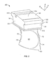
- FIG 2 is an enlarged perspective view of an exemplary stator vane 40 that may be used with gas turbine engine 10 (shown in Figure 1). More specifically, in the exemplary embodiment, stator vane 40 is coupled within a compressor, such as compressor 12 (shown in Figure 1).
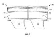
- Figure 3 is a front view of a pair of stator vanes 40 and illustrates a relative circumferential orientation of adjacent stator vanes 40 when assembled within a rotor assembly, such as gas turbine engine 10 (shown in Figure 1).
- stator vane 40 forms a portion of a ninth stage of a compressor, such as compressor 12 (shown in Figure 1).
- stator vane described herein may be advantageous with other rotary member applications known in the art.
- the description herein is therefore set forth for illustrative purposes only and is not intended to limit application of the invention to a particular stator vane, compressor, or turbine.
- the airfoil profile of the present invention is believed to be optimal in the ninth stage of compressor 12 to achieve desired interaction between other stages in compressor 12, improve aerodynamic efficiency of compressor 12; and optimize aerodynamic and mechanical loading of each stator vane during compressor operation.
- each stator vane 40 When assembled within the rotor assembly, each stator vane 40 is coupled to an engine casing (not shown) that extends circumferentially around a rotor shaft, such as shaft 18 (shown in Figure 1). As is known in the art, when fully assembled, each circumferential row of stator vanes 40 is located axially between adjacent rows of rotor blades (not shown). More specifically, stator vanes 40 are oriented to channel a fluid flow through the rotor assembly in such a manner as to facilitate enhancing engine performance. In the exemplary embodiment, circumferentially adjacent stator vanes 40 are identical and each extends radially across a flow path defined within the rotor assembly. Moreover, each stator vane 40 includes an airfoil 60 that extends radially outward from, and in the exemplary embodiment, is formed integrally with, a base or platform 62.
- Each airfoil 60 includes a first sidewall 70 and a second sidewall 72.
- First sidewall 70 is convex and defines a suction side of airfoil 60
- second sidewall 72 is concave and defines a pressure side of airfoil 60.
- Sidewalls 70 and 72 are joined together at a leading edge 74 and at an axially-spaced trailing edge 76 of airfoil 60. More specifically, airfoil trailing edge 76 is spaced chord-wise and downstream from airfoil leading edge 74.
- First and second sidewalls 70 and 72 respectively, extend longitudinally or radially outward in span from a root 78 positioned adjacent base 62 to an airfoil tip 80.
- Base 62 facilitates securing stator vanes 40 to the casing.
- base 62 is known as a "square-faced" base and includes a pair of circumferentially-spaced sides 90 and 91 that are connected together by an upstream face 92 and a downstream face 94.
- sides 90 and 91 are identical and are substantially parallel to each other.
- upstream face 92 and downstream face 94 are substantially parallel to each other.
- a pair of integrally-formed hangers 100 and 102 extend from each respective face 92 and 94.
- Hangers 100 and 102 engage the casing to facilitate securing stator vane 40 within the rotor assembly.
- each hanger 100 and 102 extends outwardly from each respective face 92 and 94 adjacent a radially outer surface 104 of base 62.
- the airfoils 60 are integrally cast with each base 62 from a directionally solidified alloy which is strengthened through solution and precipitation hardening heat treatments.
- the directional solidification affords the advantage of avoiding transverse grain boundaries, thereby increasing creep life.
- a loci of 1456 points in space that meet the unique demands of the ninth stage requirements of compressor 12 has been determined in an iterative process considering aerodynamic loading and mechanical loading of the blades under applicable operating parameters.
- the loci of points is believed to achieve a desired interaction between other stages in the compressor, aerodynamic efficiency of the compressor; and optimal aerodynamic and mechanical loading of the stator vanes during compressor operation. Additionally, the loci of points provide a manufacturable airfoil profile for fabrication of the stator vanes, and allows the compressor to run in an efficient, safe and smooth manner.
- FIG. 2 there is shown a Cartesian coordinate system for X, Y and Z values set forth in Table I which follows.
- the Cartesian coordinate system has orthogonally related X, Y and Z axes with the Z axis or datum lying substantially perpendicular to platform 62 and extending generally in a radial direction through the airfoil.
- the Y axis lies parallel to the machine centerline, i.e., the rotary axis.
- the profile of airfoil 60 can be ascertained.
- each profile section at each radial distance Z is fixed.
- the surface profiles at the various surface locations between the radial distances Z can be ascertained by connecting adjacent profiles.
- the X and Y coordinates for determining the airfoil section profile at each radial location or airfoil height Z are tabulated in the following Table I, where Z is a non-dimensionalized value equal to 0 at the upper surface of the platform 62 and equal to 1.593 at airfoil tip portion 80.
- Tabular values for X, Y, and Z coordinates are provided in inches, and represent actual airfoil profiles at ambient, non-operating or non-hot conditions for an uncoated airfoil, the coatings for which are described below. Additionally, the sign convention assigns a positive value to the value Z and positive and negative values for the coordinates X and Y, as typically used in a Cartesian coordinate system.
- the Table I values are computer-generated and shown to three decimal places. However, in view of manufacturing constraints, actual values useful for forming the airfoil are considered valid to only three decimal places for determining the profile of the airfoil. Further, there are typical manufacturing tolerances which must be accounted for in the profile of the airfoil. Accordingly, the values for the profile given in Table I are for a nominal airfoil. It will therefore be appreciated that plus or minus typical manufacturing tolerances are applicable to these X, Y and Z values and that an airfoil having a profile substantially in accordance with those values includes such tolerances. For example, a manufacturing tolerance of about ⁇ 0.160 inches is within design limits for the airfoil.
- the mechanical and aerodynamic function of the airfoils is not impaired by manufacturing imperfections and tolerances, which in different embodiments may be greater or lesser than the values set forth above.
- manufacturing tolerances may be determined to achieve a desired mean and standard deviation of manufactured airfoils in relation to the ideal airfoil profile points set forth in Table 1.
- the airfoil may also be coated for protection against corrosion and oxidation after the airfoil is manufactured, according to the values of Table I and within the tolerances explained above.
- an anti-corrosion coating or coatings is provided with a total average thickness of about 0.100 inches. Consequently, in addition to the manufacturing tolerances for the X and Y values set forth in Table I, there is also an addition to those values to account for the coating thicknesses. It is contemplated that greater or lesser coating thickness values may be employed in alternative embodiments of the invention.
- the airfoil profile set forth in Table 1 may be scaled up or down geometrically in order to be introduced into other similar machine designs. It is therefore contemplated that a scaled version of the airfoil profile set fort in Table 1 may be obtained by multiplying or dividing each of the X and Y coordinate values by a predetermined constant n. It is recognized that Table 1 could be considered a scaled profile with n set equal to 1, and greater or lesser dimensioned airfoils could be obtained by adjusting n to values greater and lesser than 1, respectively.
- each stator vane airfoil has an airfoil shape that facilitates achieving a desired interaction between other stages in the compressor, aerodynamic efficiency of the compressor; and optimal aerodynamic and mechanical loading of the stator vanes during compressor operation.
- the redefined airfoil geometry facilitates extending a useful life of the stator assembly and improving the operating efficiency of the compressor in a cost-effective and reliable manner.
- stator vanes and stator assemblies are described above in detail.
- the stator vanes are not limited to the specific embodiments described herein, but rather, components of each stator vane may be utilized independently and separately from other components described herein.
- each stator vane recessed portion can also be defined in, or used in combination with, other stator vanes or with other rotor assemblies, and is not limited to practice with only stator vane 40 as described herein. Rather, the present invention can be implemented and utilized in connection with many other vane and rotor configurations.
Landscapes
- Engineering & Computer Science (AREA)
- Mechanical Engineering (AREA)
- General Engineering & Computer Science (AREA)
- Physics & Mathematics (AREA)
- Fluid Mechanics (AREA)
- Structures Of Non-Positive Displacement Pumps (AREA)
- Turbine Rotor Nozzle Sealing (AREA)
Abstract
Description
- The present invention relates generally to stator vanes for gas turbines and, more particularly, to a novel and improved profile for a ninth stage compressor stator vane.
- In the design, fabrication and use of turbine engines, there has been an increasing tendency toward operating with higher temperatures and higher operating pressures to optimize turbine performance. Also, as existing turbine airfoils and stator vanes reach the end of their life cycle, it is desirable to replace the airfoils, while simultaneously enhancing performance of the gas turbine through redesign of the airfoils to accommodate the increased operating temperatures and pressures.
- Airfoil profiles for gas turbines have been proposed to provide improved performance, lower operating temperatures, increased creep margin and extended life in relation to conventional airfoils. See, for example,
U.S. Patent No. 5,980,209 describing an enhanced turbine blade airfoil profile. Advanced materials and new steam cooling systems now permit gas turbines to operate at, and accommodate, much higher operating temperatures, mechanical loading, and pressures than is capable in at least some known turbine engines. As a result, many system requirements must be met for each stage of each compressor used with the turbine engines in order to meet design goals including overall improved efficiency and airfoil loading. Particularly, the airfoils of the stator vanes positioned within the compressors must meet the thermal and mechanical operating requirements for each particular stage. - In one aspect of the invention, an airfoil for a stator vane is provided. The airfoil has an uncoated profile substantially in accordance with Cartesian coordinate values of X, Y and Z set forth in Table I carried only to four decimal places wherein Z is a distance from a platform on which the airfoil is mounted and X and Y are coordinates defining the profile at each distance Z from the platform.
- In another aspect of the invention, a compressor comprising at least one row of stator vanes is provided. Each of the stator vanes comprises a base and an airfoil extending therefrom. At least one of the airfoils has an airfoil shape. The airfoil shape has a nominal profile substantially in accordance with Cartesian coordinate values of X, Y and Z set forth in Table I carried only to three decimal places wherein Z is a distance from a platform on which the airfoil is mounted and X and Y ace coordinates defining the profile at each distance Z from the platform.
- In a further aspect of the invention, a stator assembly is provided. The stator assembly includes at least one stator vane including a base and an airfoil extending from the base. The airfoil has an uncoated profile substantially in accordance with Cartesian coordinate values of X, Y and Z set forth in Table I carried only to three decimal places wherein Z is a distance from a platform on which the airfoil is mounted and X and Y are coordinates defining the profile at each distance Z from the base. The profile is scalable by a predetermined constant n and manufacturable to a predetermined manufacturing tolerance.
- The invention will now be described in greater detail, by way of example, with reference to the drawings, in which:-
- Figure 1 is schematic illustration of an exemplary gas turbine engine;
- Figure 2 is an enlarged perspective view of an exemplary stator vane that may be used with the gas turbine engine shown in Figure 1; and
- Figure 3 is a front view of a pair of the stator vanes shown in Figure 2 and illustrates a relative circumferential orientation of adjacent stator vanes as positioned when assembled within an engine, such as the gas turbine engine shown in Figure 1.
- Figure 1 is a schematic illustration of an exemplary
gas turbine engine 10 coupled to anelectric generator 16. In the exemplary embodiment,gas turbine system 10 includes acompressor 12, aturbine 14, andgenerator 16 arranged in a single monolithic rotor orshaft 18. In an alternative embodiment,shaft 18 is segmented into a plurality of shaft segments, wherein each shaft segment is coupled to an adjacent shaft segment to formshaft 18.Compressor 12 supplies compressed air to acombustor 20 wherein the air is mixed withfuel 22 supplied thereto. In one embodiment,engine 10 is a 6C gas turbine engine commercially available from General Electric Company, Greenville, South Carolina - In operation, air flows through
compressor 12 and compressed air is supplied tocombustor 20.Combustion gases 28 fromcombustor 20propels turbines 14.Turbine 14 rotatesshaft 18,compressor 12, andelectric generator 16 about alongitudinal axis 30. - Figure 2 is an enlarged perspective view of an
exemplary stator vane 40 that may be used with gas turbine engine 10 (shown in Figure 1). More specifically, in the exemplary embodiment,stator vane 40 is coupled within a compressor, such as compressor 12 (shown in Figure 1). Figure 3 is a front view of a pair ofstator vanes 40 and illustrates a relative circumferential orientation ofadjacent stator vanes 40 when assembled within a rotor assembly, such as gas turbine engine 10 (shown in Figure 1). In the exemplary embodiment,stator vane 40 forms a portion of a ninth stage of a compressor, such as compressor 12 (shown in Figure 1). As will be appreciated by one of ordinary skill in the art, the stator vane described herein may be advantageous with other rotary member applications known in the art. The description herein is therefore set forth for illustrative purposes only and is not intended to limit application of the invention to a particular stator vane, compressor, or turbine. - The airfoil profile of the present invention, as described below, is believed to be optimal in the ninth stage of
compressor 12 to achieve desired interaction between other stages incompressor 12, improve aerodynamic efficiency ofcompressor 12; and optimize aerodynamic and mechanical loading of each stator vane during compressor operation. - When assembled within the rotor assembly, each
stator vane 40 is coupled to an engine casing (not shown) that extends circumferentially around a rotor shaft, such as shaft 18 (shown in Figure 1). As is known in the art, when fully assembled, each circumferential row ofstator vanes 40 is located axially between adjacent rows of rotor blades (not shown). More specifically,stator vanes 40 are oriented to channel a fluid flow through the rotor assembly in such a manner as to facilitate enhancing engine performance. In the exemplary embodiment, circumferentiallyadjacent stator vanes 40 are identical and each extends radially across a flow path defined within the rotor assembly. Moreover, eachstator vane 40 includes anairfoil 60 that extends radially outward from, and in the exemplary embodiment, is formed integrally with, a base orplatform 62. - Each
airfoil 60 includes afirst sidewall 70 and asecond sidewall 72.First sidewall 70 is convex and defines a suction side ofairfoil 60, andsecond sidewall 72 is concave and defines a pressure side ofairfoil 60.Sidewalls edge 74 and at an axially-spacedtrailing edge 76 ofairfoil 60. More specifically, airfoiltrailing edge 76 is spaced chord-wise and downstream fromairfoil leading edge 74. First andsecond sidewalls adjacent base 62 to anairfoil tip 80. -
Base 62 facilitates securingstator vanes 40 to the casing. In the exemplary embodiment,base 62 is known as a "square-faced" base and includes a pair of circumferentially-spacedsides upstream face 92 and adownstream face 94. In the exemplary embodiment,sides face 92 anddownstream face 94 are substantially parallel to each other. - A pair of integrally-formed
hangers respective face Hangers stator vane 40 within the rotor assembly. In the exemplary embodiment, eachhanger respective face outer surface 104 ofbase 62. - In the exemplary embodiment, the
airfoils 60 are integrally cast with eachbase 62 from a directionally solidified alloy which is strengthened through solution and precipitation hardening heat treatments. The directional solidification affords the advantage of avoiding transverse grain boundaries, thereby increasing creep life. - Via development of source codes, models and design practices, a loci of 1456 points in space that meet the unique demands of the ninth stage requirements of
compressor 12 has been determined in an iterative process considering aerodynamic loading and mechanical loading of the blades under applicable operating parameters. The loci of points is believed to achieve a desired interaction between other stages in the compressor, aerodynamic efficiency of the compressor; and optimal aerodynamic and mechanical loading of the stator vanes during compressor operation. Additionally, the loci of points provide a manufacturable airfoil profile for fabrication of the stator vanes, and allows the compressor to run in an efficient, safe and smooth manner. - Referring to Figure 2, there is shown a Cartesian coordinate system for X, Y and Z values set forth in Table I which follows. The Cartesian coordinate system has orthogonally related X, Y and Z axes with the Z axis or datum lying substantially perpendicular to
platform 62 and extending generally in a radial direction through the airfoil. The Y axis lies parallel to the machine centerline, i.e., the rotary axis. By defining X and Y coordinate values at selected locations in the radial direction, i.e., in a Z direction, the profile ofairfoil 60 can be ascertained. By connecting the X and Y values with smooth continuing arcs, each profile section at each radial distance Z is fixed. The surface profiles at the various surface locations between the radial distances Z can be ascertained by connecting adjacent profiles. - The X and Y coordinates for determining the airfoil section profile at each radial location or airfoil height Z are tabulated in the following Table I, where Z is a non-dimensionalized value equal to 0 at the upper surface of the
platform 62 and equal to 1.593 atairfoil tip portion 80. Tabular values for X, Y, and Z coordinates are provided in inches, and represent actual airfoil profiles at ambient, non-operating or non-hot conditions for an uncoated airfoil, the coatings for which are described below. Additionally, the sign convention assigns a positive value to the value Z and positive and negative values for the coordinates X and Y, as typically used in a Cartesian coordinate system. - The Table I values are computer-generated and shown to three decimal places. However, in view of manufacturing constraints, actual values useful for forming the airfoil are considered valid to only three decimal places for determining the profile of the airfoil. Further, there are typical manufacturing tolerances which must be accounted for in the profile of the airfoil. Accordingly, the values for the profile given in Table I are for a nominal airfoil. It will therefore be appreciated that plus or minus typical manufacturing tolerances are applicable to these X, Y and Z values and that an airfoil having a profile substantially in accordance with those values includes such tolerances. For example, a manufacturing tolerance of about ±0.160 inches is within design limits for the airfoil. Thus, the mechanical and aerodynamic function of the airfoils is not impaired by manufacturing imperfections and tolerances, which in different embodiments may be greater or lesser than the values set forth above. As appreciated by those in the art, manufacturing tolerances may be determined to achieve a desired mean and standard deviation of manufactured airfoils in relation to the ideal airfoil profile points set forth in Table 1.
- In addition, and as noted previously, the airfoil may also be coated for protection against corrosion and oxidation after the airfoil is manufactured, according to the values of Table I and within the tolerances explained above. In an exemplary embodiment, an anti-corrosion coating or coatings is provided with a total average thickness of about 0.100 inches. Consequently, in addition to the manufacturing tolerances for the X and Y values set forth in Table I, there is also an addition to those values to account for the coating thicknesses. It is contemplated that greater or lesser coating thickness values may be employed in alternative embodiments of the invention.
- As the ninth stage stator vane assembly, including the aforementioned airfoils, heats up during operation, applied stress and temperature on the turbine blades inevitably leads to some deformation of the airfoil shape, and hence there is some change or displacement in the X, Y and Z coordinates set forth in Table 1 as the engine is operated. While it is not possible to measure the changes in the airfoil coordinates in operation, it has been determined that the loci of points set forth in Table 1 plus the deformation in use, allows the compressor to run in an efficient, safe and smooth manner.
- It is appreciated that the airfoil profile set forth in Table 1 may be scaled up or down geometrically in order to be introduced into other similar machine designs. It is therefore contemplated that a scaled version of the airfoil profile set fort in Table 1 may be obtained by multiplying or dividing each of the X and Y coordinate values by a predetermined constant n. It is recognized that Table 1 could be considered a scaled profile with n set equal to 1, and greater or lesser dimensioned airfoils could be obtained by adjusting n to values greater and lesser than 1, respectively.
- The above-described stator vanes provide a cost-effective and reliable method for optimizing performance of a rotor assembly. More specifically, each stator vane airfoil has an airfoil shape that facilitates achieving a desired interaction between other stages in the compressor, aerodynamic efficiency of the compressor; and optimal aerodynamic and mechanical loading of the stator vanes during compressor operation. As a result, the redefined airfoil geometry facilitates extending a useful life of the stator assembly and improving the operating efficiency of the compressor in a cost-effective and reliable manner.
- Exemplary embodiments of stator vanes and stator assemblies are described above in detail. The stator vanes are not limited to the specific embodiments described herein, but rather, components of each stator vane may be utilized independently and separately from other components described herein. For example, each stator vane recessed portion can also be defined in, or used in combination with, other stator vanes or with other rotor assemblies, and is not limited to practice with
only stator vane 40 as described herein. Rather, the present invention can be implemented and utilized in connection with many other vane and rotor configurations.TABLE 1 X-LOC Y-LOC Z-LOC X-LOC Y-LOC Z-LOC X-LOC Y-LOC Z-LOC 0.61 -0.717 0 -0.684 0.03 0 -0.46 -0.039 0 0.61 -0.718 0 -0.708 0.068 0 -0.42 -0.072 0 0.609 -0.719 0 -0.73 0.106 0 -0.377 -0.106 0 0.607 -0.722 0 -0.748 0.141 0 -0.335 -0.139 0 0.603 -0.724 0 -0.764 0.173 0 -0.292 -0.171 0 0.595 -0.726 0 -0.776 0.203 0 -0.248 -0.202 0 0.584 -0.722 0 -0.786 0.229 0 -0.204 -0.233 0 0.57 -0.717 0 -0.794 0.252 0 -0.159 -0.264 0 0.553 -0.711 0 -0.8 0.272 0 -0.114 -0.294 0 0.529 -0.703 0 -0.805 0.289 0 -0.069 -0.323 0 0.503 -0.693 0 -0.808 0.303 0 -0.023 -0.352 0 0.474 -0.684 0 -0.811 0.316 0 0.022 -0.381 0 0.442 -0.673 0 -0.812 0.325 0 0.068 -0.409 0 0.407 -0.66 0 -0.813 0.333 0 0.114 -0.437 0 0.368 -0.647 0 -0.813 0.339 0 0.159 -0.464 0 0.327 -0.632 0 -0.812 0.343 0 0.203 -0.489 0 0.284 -0.617 0 -0.81 0.346 0 0.245 -0.513 0 0.24 -0.6 0 -0.807 0.348 0 0.286 -0.536 0 0.195 -0.583 0 -0.805 0.349 0 0.325 -0.558 0 0.148 -0.564 0 -0.801 0.348 0 0.363 -0.579 0 0.099 -0.543 0 -0.797 0.346 0 0.399 -0.598 0 0.049 -0.522 0 -0.793 0.342 0 0.435 -0.617 0 -0.002 -0.498 0 -0.788 0.336 0 0.467 -0.633 0 -0.053 -0.474 0 -0.783 0.329 0 0.495 -0.648 0 -0.104 -0.449 0 -0.776 0.32 0 0.521 -0.661 0 -0.154 -0.422 0 -0.768 0.308 0 0.546 -0.672 0 -0.203 -0.394 0 -0.759 0.294 0 0.567 -0.682 0 -0.251 -0.366 0 -0.748 0.277 0 0.583 -0.69 0 -0.299 -0.335 0 -0.735 0.257 0 0.596 -0.695 0 -0.346 -0.304 0 -0.719 0.235 0 0.606 -0.7 0 -0.392 -0.271 0 -0.701 0.21 0 0.61 -0.707 0 -0.436 -0.237 0 -0.68 0.183 0 0.611 -0.711 0 -0.479 -0.201 0 -0.656 0.154 0 0.611 -0.714 0 -0.521 -0.163 0 -0.629 0.123 0 0.61 -0.716 0 -0.559 -0.125 0 -0.599 0.092 0 0.61 -0.716 0 -0.594 -0.086 0 -0.568 0.06 0 0.61 -0.717 0 -0.627 -0.047 0 -0.534 0.027 0 -0.657 -0.008 0 -0.498 -0.006 0 0.628 -0.707 0.037 -0.674 0.038 0.037 -0.447 -0.027 0.037 0.627 -0.707 0.037 -0.699 0.076 0.037 -0.406 -0.06 0.037 0.627 -0.709 0.037 -0.722 0.113 0.037 -0.364 -0.093 0.037 0.625 -0.711 0.037 -0.741 0.147 0.037 -0.321 -0.126 0.037 0.621 -0.714 0.037 -0.758 0.179 0.037 -0.277 -0.158 0.037 0.613 -0.715 0.037 -0.771 0.207 0.037 -0.233 -0.189 0.037 0.602 -0.712 0.037 -0.782 0.233 0.037 -0.188 -0.22 0.037 0.588 -0.707 0.037 -0.791 0.256 0.037 -0.143 -0.25 0.037 0.571 -0.7 0.037 -0.797 0.276 0.037 -0.098 -0.28 0.037 0.548 -0.692 0.037 -0.803 0.293 0.037 -0.053 -0.31 0.037 0.521 -0.682 0.037 -0.807 0.307 0.037 -0.007 -0.339 0.037 0.493 -0.672 0.037 -0.81 0.319 0.037 0.039 -0.367 0.037 0.461 -0.661 0.037 -0.811 0.329 0.037 0.085 -0.395 0.037 0.425 -0.648 0.037 -0.812 0.336 0.037 0.132 -0.423 0.037 0.386 -0.634 0.037 -0.812 0.342 0.037 0.177 -0.45 0.037 0.346 -0.619 0.037 -0.811 0.347 0.037 0.221 -0.475 0.037 0.303 -0.603 0.037 -0.809 0.35 0.037 0.263 -0.5 0.037 0.259 -0.586 0.037 -0.807 0.351 0.037 0.304 -0.523 0.037 0.214 -0.568 0.037 -0.804 0.352 0.037 0.343 -0.545 0.037 0.167 -0.549 0.037 -0.801 0.351 0.037 0.381 -0.566 0.037 0.118 -0.529 0.037 -0.797 0.349 0.037 0.417 -0.586 0.037 0.068 -0.507 0.037 -0.793 0.346 0.037 0.452 -0.605 0.037 0.017 -0.483 0.037 -0.788 0.341 0.037 0.484 -0.621 0.037 -0.034 -0.459 0.037 -0.782 0.333 0.037 0.513 -0.636 0.037 -0.085 -0.434 0.037 -0.774 0.324 0.037 0.539 -0.649 0.037 -0.135 -0.407 0.037 -0.766 0.312 0.037 0.564 -0.661 0.037 -0.184 -0.38 0.037 -0.756 0.299 0.037 0.585 -0.671 0.037 -0.233 -0.351 0.037 -0.745 0.282 0.037 0.601 -0.679 0.037 -0.281 -0.322 0.037 -0.731 0.263 0.037 0.614 -0.685 0.037 -0.328 -0.29 0.037 -0.714 0.242 0.037 0.624 -0.69 0.037 -0.374 -0.258 0.037 -0.695 0.217 0.037 0.628 -0.697 0.037 -0.419 -0.224 0.037 -0.673 0.191 0.037 0.629 -0.701 0.037 -0.463 -0.189 0.037 -0.648 0.163 0.037 0.629 -0.704 0.037 -0.505 -0.151 0.037 -0.62 0.132 0.037 0.628 -0.705 0.037 -0.545 -0.113 0.037 -0.589 0.101 0.037 0.628 -0.706 0.037 -0.581 -0.075 0.037 -0.557 0.07 0.037 0.628 -0.706 0.037 -0.615 -0.037 0.037 -0.522 0.038 0.037 -0.645 0.001 0.037 -0.486 0.006 0.037 0.651 -0.693 0.073 -0.663 0.046 0.073 -0.435 -0.015 0.073 0.651 -0.693 0.073 -0.689 0.083 0.073 -0.393 -0.048 0.073 0.65 -0.695 0.073 -0.713 0.119 0.073 -0.35 -0.081 0.073 0.648 -0.697 0.073 -0.734 0.153 0.073 -0.306 -0.114 0.073 0.645 -0.7 0.073 -0.751 0.184 0.073 -0.262 -0.146 0.073 0.636 -0.702 0.073 -0.766 0.213 0.073 -0.218 -0.177 0.073 0.626 -0.698 0.073 -0.778 0.238 0.073 -0.173 -0.208 0.073 0.611 -0.692 0.073 -0.787 0.261 0.073 -0.127 -0.238 0.073 0.594 -0.686 0.073 -0.795 0.28 0.073 -0.081 -0.268 0.073 0.571 -0.677 0.073 -0.801 0.297 0.073 -0.036 -0.297 0.073 0.544 -0.668 0.073 -0.805 0.311 0.073 0.011 -0.326 0.073 0.516 -0.658 0.073 -0.808 0.323 0.073 0.057 -0.354 0.073 0.483 -0.646 0.073 -0.81 0.333 0.073 0.104 -0.382 0.073 0.448 -0.633 0.073 -0.811 0.34 0.073 0.151 -0.41 0.073 0.409 -0.619 0.073 -0.812 0.346 0.073 0.196 -0.437 0.073 0.368 -0.605 0.073 -0.811 0.351 0.073 0.24 -0.462 0.073 0.325 -0.589 0.073 -0.809 0.354 0.073 0.283 -0.486 0.073 0.281 -0.572 0.073 -0.807 0.356 0.073 0.324 -0.509 0.073 0.235 -0.554 0.073 -0.804 0.357 0.073 0.364 -0.531 0.073 0.188 -0.535 0.073 -0.8 0.356 0.073 0.402 -0.552 0.073 0.139 -0.514 0.073 -0.796 0.354 0.073 0.439 -0.572 0.073 0.089 -0.493 0.073 -0.792 0.351 0.073 0.475 -0.591 0.073 0.037 -0.469 0.073 -0.787 0.346 0.073 0.507 -0.607 0.073 -0.014 -0.445 0.073 -0.78 0.339 0.073 0.536 -0.622 0.073 -0.065 -0.42 0.073 -0.773 0.33 0.073 0.562 -0.635 0.073 -0.115 -0.394 0.073 -0.764 0.318 0.073 0.587 -0.647 0.073 -0.165 -0.366 0.073 -0.754 0.305 0.073 0.608 -0.657 0.073 -0.214 -0.338 0.073 -0.741 0.289 0.073 0.624 -0.665 0.073 -0.262 -0.308 0.073 -0.727 0.27 0.073 0.638 -0.671 0.073 -0.309 -0.277 0.073 -0.71 0.249 0.073 0.647 -0.676 0.073 -0.356 -0.245 0.073 -0.69 0.225 0.073 0.652 -0.683 0.073 -0.402 -0.212 0.073 -0.667 0.199 0.073 0.652 -0.687 0.073 -0.447 -0.177 0.073 -0.641 0.171 0.073 0.652 -0.69 0.073 -0.49 -0.14 0.073 -0.611 0.142 0.073 0.652 -0.691 0.073 -0.53 -0.103 0.073 -0.58 0.111 0.073 0.651 -0.692 0.073 -0.567 -0.066 0.073 -0.547 0.08 0.073 0.651 -0.692 0.073 -0.602 -0.028 0.073 -0.511 0.049 0.073 -0.634 0.009 0.073 -0.474 0.017 0.073 0.698 -0.663 0.145 -0.643 0.065 0.145 -0.413 0.009 0.145 0.698 -0.664 0.145 -0.672 0.101 0.145 -0.37 -0.023 0.145 0.697 -0.665 0.145 -0.698 0.136 0.145 -0.326 -0.056 0.145 0.695 -0.668 0.145 -0.72 0.169 0.145 -0.281 -0.088 0.145 0.692 -0.671 0.145 -0.74 0.2 0.145 -0.236 -0.12 0.145 0.683 -0.672 0.145 -0.756 0.228 0.145 -0.19 -0.151 0.145 0.672 -0.668 0.145 -0.769 0.253 0.145 -0.144 -0.182 0.145 0.658 -0.663 0.145 -0.78 0.275 0.145 -0.097 -0.212 0.145 0.64 -0.656 0.145 -0.789 0.294 0.145 -0.051 -0.241 0.145 0.617 -0.648 0.145 -0.796 0.311 0.145 -0.004 -0.271 0.145 0.59 -0.638 0.145 -0.801 0.325 0.145 0.043 -0.299 0.145 0.561 -0.628 0.145 -0.806 0.337 0.145 0.091 -0.328 0.145 0.528 -0.617 0.145 -0.808 0.346 0.145 0.139 -0.356 0.145 0.492 -0.604 0.145 -0.81 0.354 0.145 0.186 -0.384 0.145 0.453 -0.59 0.145 -0.81 0.359 0.145 0.233 -0.41 0.145 0.411 -0.576 0.145 -0.81 0.364 0.145 0.278 -0.435 0.145 0.368 -0.56 0.145 -0.808 0.368 0.145 0.322 -0.459 0.145 0.324 -0.543 0.145 -0.806 0.37 0.145 0.364 -0.482 0.145 0.277 -0.525 0.145 -0.803 0.371 0.145 0.404 -0.504. 0.145 0.229 -0.506 0.145 -0.8 0.37 0.145 0.444 -0.524 0.145 0.18 -0.486 0.145 -0.795 0.368 0.145 0.481 -0.544 0.145 0.129 -0.464 0.145 -0.791 0.365 0.145 0.517 -0.562 0.145 0.077 -0.441 0.145 -0.785 0.36 0.145 0.55 -0.579 0.145 0.025 -0.417 0.145 -0.778 0.354 0.145 0.58 -0.593 0.145 -0.027 -0.392 0.145 -0.77 0.345 0.145 0.607 -0.606 0.145 -0.078 -0.366 0.145 -0.761 0.334 0.145 0.632 -0.618 0.145 -0.128 -0.339 0.145 -0.749 0.321 0.145 0.654 -0.628 0.145 -0.178 -0.311 0.145 -0.736 0.306 0.145 0.671 -0.635 0.145 -0.227 -0.281 0.145 -0.72 0.288 0.145 0.684 -0.641 0.145 -0.276 -0.251 0.145 -0.701 0.267 0.145 0.694 -0.646 0.145 -0.324 -0.22 0.145 -0.68 0.244 0.145 0.699 -0.653 0.145 -0.371 -0.187 0.145 -0.655 0.219 0.145 0.699 -0.658 0.145 -0.417 -0.153 0.145 -0.628 0.192 0.145 0.699 -0.66 0.145 -0.461 -0.117 0.145 -0.597 0.163 0.145 0.699 -0.662 0.145 -0.503 -0.081 0.145 -0.564 0.133 0.145 0.698 -0.663 0.145 -0.542 -0.044 0.145 -0.529 0.103 0.145 0.698 -0.663 0.145 -0.579 -0.008 0.145 -0.492 0.072 0.145 -0.612 0.029 0.145 -0.454 0.041 0.145 0.794 -0.578 0.338 -0.607 0.122 0.338 -0.376 0.072 0.338 0.793 -0.579 0.338 -0.639 0.157 0.338 -0.331 0.041 0.338 0.793 -0.58 0.338 -0.668 0.191 0.338 -0.284 0.009 0.338 0.791 -0.583 0.338 -0.694 0.222 0.338 -0.236 -0.023 0.338 0.787 -0.586 0.338 -0.717 0.252 0.338 -0.189 -0.054 0.338 0.779 -0.587 0.338 -0.736 0.279 0.338 -0.14 -0.085 0.338 0.767 -0.584 0.338 -0.753 0.303 0.338 -0.092 -0.114 0.338 0.752 -0.579 0.338 -0.766 0.324 0.338 -0.043 -0.144 0.338 0.734 -0.573 0.338 -0.777 0.343 0.338 0.006 -0.173 0.338 0.71 -0.565 0.338 -0.786 0.359 0.338 0.055 -0.201 0.338 0.682 -0.556 0.338 -0.793 0.373 0.338 0.105 -0.229 0.338 0.652 -0.546 0.338 -0.799 0.384 0.338 0.155 -0.257 0.338 0.618 -0.536 0.338 -0.803 0.393 0.338 0.205 -0.284 0.338 0.581 -0.524 0.338 -0.805 0.401 0.338 0.255 -0.311 0.338 0.54 -0.51 0.338 -0.807 0.407 0.338 0.304 -0.337 0.338 0.498 -0.496 0.338 -0.807 0.412 0.338 0.351 -0.361 0.338 0.453 -0.481 0.338 -0.806 0.415 0.338 0.397 -0.384 0.338 0.407 -0.465 0.338 -0.804 0.418 0.338 0.441 -0.406 0.338 0.359 -0.447 0.338 -0.802 0.419 0.338 0.484 -0.427 0.338 0.31 -0.429 0.338 -0.798 0.419 0.338 0.525 -0.447 0.338 0.259 -0.409 0.338 -0.793 0.417 0.338 0.565 -0.465 0.338 0.206 -0.388 0.338 -0.788 0.414 0.338 0.603 -0.482 0.338 0.152 -0.365 0.338 -0.782 0.41 0.338 0.638 -0.498 0.338 0.099 -0.342 0.338 -0.775 0.403 0.338 0.669 -0.512 0.338 0.045 -0.317 0.338 -0.765 0.395 0.338 0.697 -0.524 0.338 -0.008 -0.292 0.338 -0.754 0.385 0.338 0.723 -0.534 0.338 -0.06 -0.266 0.338 -0.741 0.372 0.338 0.746 -0.544 0.338 -0.112 -0.239 0.338 -0.726 0.358 0.338 0.764 -0.551 0.338 -0.163 -0.211 0.338 -0.708 0.341 0.338 0.778 -0.556 0.338 -0.214 -0.181 0.338 -0.687 0.322 0.338 0.789 -0.561 0.338 -0.264 -0.151 0.338 -0.663 0.3 0.338 0.794 -0.567 0.338 -0.314 -0.119 0.338 -0.636 0.276 0.338 0.795 -0.572 0.338 -0.362 -0.086 0.338 -0.606 0.25 0.338 0.795 -0.575 0.338 -0.409 -0.052 0.338 -0.572 0.222 0.338 0.794 -0.576 0.338 -0.454 -0.017 0.338 -0.537 0.193 0.338 0.794 -0.577 0.338 -0.496 0.018 0.338 -0.5 0.164 0.338 0.794 -0.577 0.338 -0.536 0.053 0.338 -0.46 0.134 0.338 -0.573 0.088 0.338 -0.419 0.103 0.338 0.698 -0.629 1.593 -0.647 0.146 1.593 -0.399 0.104 1.593 0.698 -0.63 1.593 -0.674 0.186 1.593 -0.359 0.067 1.593 0.697 -0.632 1.593 -0.698 0.224 1.593 -0.317 0.029 1.593 0.695 -0.634 1.593 -0.72 0.259 1.593 -0.275 -0.009 1.593 0.692 -0.637 1.593 -0.738 0.292 1.593 -0.233 -0.046 1.593 0.683 -0.64 1.593 -0.754 0.321 1.593 -0.19 -0.083 1.593 0.671 -0.637 1.593 -0.768 0.347 1.593 -0.147 -0.119 1.593 0.656 -0.633 1.593 -0.779 0.371 1.593 -0.103 -0.155 1.593 0.637 -0.629 1.593 -0.787 0.39 1.593 -0.058 -0.19 1.593 0.612 -0.623 1.593 -0.794 0.408 1.593 -0.014 -0.224 1.593 0.583 -0.617 1.593 -0.8 0.422 1.593 0.031 -0.258 1.593 0.552 -0.61 1.593 -0.804 0.434 1.593 0.077 -0.291 1.593 0.518 -0.602 1.593 -0.806 0.444 1.593 0.123 -0.323 1.593 0.479 -0.593 1.593 -0.807 0.452 1.593 0.17 -0.354 1.593 0.437 -0.582 1.593 -0.807 0.458 1.593 0.216 -0.384 1.593 0.394 -0.57 1.593 -0.806 0.463 1.593 0.261 -0.411 1.593 0.348 -0.556 1.593 -0.804 0.467 1.593 0.305 -0.437 1.593 0.301 -0.541 1.593 -0.801 0.469 1.593 0.347 -0.462 1.593 0.253 -0.524 1.593 -0.799 0.47 1.593 0.389 -0.484 1.593 0.203 -0.505 1.593 -0.795 0.47 1.593 0.429 -0.505 1.593 0.152 -0.485 1.593 -0.791 0.469 1.593 0.467 -0.524 1.593 0.1 -0.462 1.593 -0.785 0.467 1.593 0.505 -0.541 1.593 0.046 -0.437 1.593 -0.779 0.464 1.593 0.539 -0.556 1.593 -0.007 -0.41 1.593 -0.771 0.458 1.593 0.571 -0.569 1.593 -0.058 -0.382 1.593 -0.761 0.45 1.593 0.599 -0.58 1.593 -0.109 -0.352 1.593 -0.75 0.441 1.593 0.625 -0.59 1.593 -0.16 -0.321 1.593 -0.737 0.429 1.593 0.648 -0.598 1.593 -0.209 -0.288 1.593 -0.722 0.415 1.593 0.666 -0.604 1.593 -0.257 -0.254 1.593 -0.704 0.398 1.593 0.681 -0.609 1.593 -0.304 -0.218 1.593 -0.684 0.378 1.593 0.691 -0.613 1.593 -0.349 -0.18 1.593 -0.661 0.356 1.593 0.697 -0.619 1.593 -0.394 -0.141 1.593 -0.635 0.331 1.593 0.699 -0.623 1.593 -0.437 -0.101 1.593 -0.607 0.303 1.593 0.699 -0.626 1.593 -0.479 -0.059 1.593 -0.576 0.273 1.593 0.698 -0.628 1.593 -0.518 -0.017 1.593 -0.544 0.241 1.593 0.698 -0.629 1.593 -0.554 0.024 1.593 -0.51 0.208 1.593 0.698 -0.629 1.593 -0.587 0.066 1.593 -0.475 0.174 1.593 -0.619 0.106 1.593 -0.438 0.14 1.593
Claims (10)
- An airfoil (60) for a stator vane (40) having an uncoated profile substantially in accordance with Cartesian coordinate values of X, Y and Z set forth in Table I carried only to four decimal places wherein Z is a distance from a platform (62) on which the airfoil is mounted and X and Y are coordinates defining the profile at each distance Z from the platform.
- An airfoil (60) in accordance with Claim 1 wherein said airfoil comprises a ninth stage of a compressor (12).
- An airfoil (60) in accordance with Claim 1 wherein said airfoil profile lies in an envelope within +/- 0.160 inches in a direction normal to any airfoil surface location.
- An airfoil (60) in accordance with Claim 1 wherein said airfoil profile facilitates optimizing an aerodynamic efficiency of said airfoil.
- An airfoil (60) in accordance with Claim 1 in combination with a base (62) extending integrally from said platform, said airfoil being formed via a casting process.
- A compressor (12) comprising at least one row of stator vanes (40) wherein each of said stator vanes comprises a base (62) and an airfoil (60) extending therefrom, at least one of said airfoils having an airfoil shape, said airfoil shape having a nominal profile substantially in accordance with Cartesian coordinate values of X, Y and Z set forth in Table I carried only to three decimal places wherein Z is a distance from an upper surface of said base from which said airfoil extends and X and Y are coordinates defining the profile at each distance Z from said base.
- A compressor (12) in accordance with Claim 6 wherein each said airfoil shape is defined by the profile sections at the Z distances being joined smoothly with one another to form a complete airfoil shape.
- A compressor (12) in accordance with Claim 6 wherein said at least one airfoil (60) further comprises a coating extending upon said at least one airfoil, said coating having a thickness of about 0.100 inches or less.
- A compressor (12) in accordance with Claim 6 wherein said at least one row of stator vanes (40) comprises a ninth stage of said compressor.
- A stator assembly comprising at least one stator vane (40) comprising a base (62) and an airfoil (60) extending from said base, wherein said airfoil comprises an uncoated profile substantially in accordance with Cartesian coordinate values of X, Y and Z set forth in Table I carried only to three decimal places wherein Z is a distance from an upper surface of from which said airfoil extends and X and Y are coordinates defining the profile at each distance Z from said base, said profile scalable by a predetermined constant n and manufacturable to a predetermined manufacturing tolerance.
Applications Claiming Priority (1)
| Application Number | Priority Date | Filing Date | Title |
|---|---|---|---|
| US11/214,499 US7384243B2 (en) | 2005-08-30 | 2005-08-30 | Stator vane profile optimization |
Publications (2)
| Publication Number | Publication Date |
|---|---|
| EP1760263A2 true EP1760263A2 (en) | 2007-03-07 |
| EP1760263A3 EP1760263A3 (en) | 2010-03-10 |
Family
ID=37489861
Family Applications (1)
| Application Number | Title | Priority Date | Filing Date |
|---|---|---|---|
| EP06254333A Withdrawn EP1760263A3 (en) | 2005-08-30 | 2006-08-17 | Stator vane profile optimization |
Country Status (5)
| Country | Link |
|---|---|
| US (1) | US7384243B2 (en) |
| EP (1) | EP1760263A3 (en) |
| JP (1) | JP2007064221A (en) |
| KR (1) | KR101338585B1 (en) |
| CN (1) | CN1924299B (en) |
Cited By (1)
| Publication number | Priority date | Publication date | Assignee | Title |
|---|---|---|---|---|
| US8734113B2 (en) | 2010-07-26 | 2014-05-27 | Snecma | Optimized aerodynamic profile for a turbine vane, in particular for a nozzle of the fourth stage of a turbine |
Families Citing this family (54)
| Publication number | Priority date | Publication date | Assignee | Title |
|---|---|---|---|---|
| US7329092B2 (en) * | 2006-01-27 | 2008-02-12 | General Electric Company | Stator blade airfoil profile for a compressor |
| US7329093B2 (en) * | 2006-01-27 | 2008-02-12 | General Electric Company | Nozzle blade airfoil profile for a turbine |
| US7306436B2 (en) * | 2006-03-02 | 2007-12-11 | Pratt & Whitney Canada Corp. | HP turbine blade airfoil profile |
| US7467926B2 (en) * | 2006-06-09 | 2008-12-23 | General Electric Company | Stator blade airfoil profile for a compressor |
| US7581930B2 (en) * | 2006-08-16 | 2009-09-01 | United Technologies Corporation | High lift transonic turbine blade |
| US7611326B2 (en) * | 2006-09-06 | 2009-11-03 | Pratt & Whitney Canada Corp. | HP turbine vane airfoil profile |
| US7572105B2 (en) * | 2006-10-25 | 2009-08-11 | General Electric Company | Airfoil shape for a compressor |
| US7520729B2 (en) * | 2006-10-25 | 2009-04-21 | General Electric Company | Airfoil shape for a compressor |
| US7572104B2 (en) * | 2006-10-25 | 2009-08-11 | General Electric Company | Airfoil shape for a compressor |
| US7517196B2 (en) * | 2006-10-25 | 2009-04-14 | General Electric Company | Airfoil shape for a compressor |
| US7566202B2 (en) * | 2006-10-25 | 2009-07-28 | General Electric Company | Airfoil shape for a compressor |
| US7517188B2 (en) * | 2006-10-25 | 2009-04-14 | General Electric Company | Airfoil shape for a compressor |
| US7530793B2 (en) * | 2006-10-25 | 2009-05-12 | General Electric Company | Airfoil shape for a compressor |
| US7517197B2 (en) * | 2006-10-25 | 2009-04-14 | General Electric Company | Airfoil shape for a compressor |
| US7513748B2 (en) * | 2006-10-25 | 2009-04-07 | General Electric Company | Airfoil shape for a compressor |
| US7517190B2 (en) * | 2006-10-25 | 2009-04-14 | General Electric Company | Airfoil shape for a compressor |
| US7513749B2 (en) * | 2006-10-25 | 2009-04-07 | General Electric Company | Airfoil shape for a compressor |
| US7510378B2 (en) * | 2006-10-25 | 2009-03-31 | General Electric Company | Airfoil shape for a compressor |
| US7534092B2 (en) * | 2006-10-25 | 2009-05-19 | General Electric Company | Airfoil shape for a compressor |
| US7497665B2 (en) * | 2006-11-02 | 2009-03-03 | General Electric Company | Airfoil shape for a compressor |
| US7524170B2 (en) * | 2006-11-02 | 2009-04-28 | General Electric Company | Airfoil shape for a compressor |
| US7537434B2 (en) * | 2006-11-02 | 2009-05-26 | General Electric Company | Airfoil shape for a compressor |
| US7568892B2 (en) * | 2006-11-02 | 2009-08-04 | General Electric Company | Airfoil shape for a compressor |
| US7559746B2 (en) * | 2006-11-22 | 2009-07-14 | Pratt & Whitney Canada Corp. | LP turbine blade airfoil profile |
| US7559747B2 (en) * | 2006-11-22 | 2009-07-14 | Pratt & Whitney Canada Corp. | Turbine exhaust strut airfoil profile |
| US7559748B2 (en) * | 2006-11-28 | 2009-07-14 | Pratt & Whitney Canada Corp. | LP turbine blade airfoil profile |
| US8113786B2 (en) * | 2008-09-12 | 2012-02-14 | General Electric Company | Stator vane profile optimization |
| EP2379276A4 (en) * | 2008-12-19 | 2012-06-27 | Volvo Aero Corp | Spoke for a stator component, stator component and method for manufacturing a stator component |
| US7988424B2 (en) * | 2009-03-25 | 2011-08-02 | General Electric Company | Bucket for the last stage of a steam turbine |
| US8356975B2 (en) * | 2010-03-23 | 2013-01-22 | United Technologies Corporation | Gas turbine engine with non-axisymmetric surface contoured vane platform |
| US9976433B2 (en) | 2010-04-02 | 2018-05-22 | United Technologies Corporation | Gas turbine engine with non-axisymmetric surface contoured rotor blade platform |
| US8105044B2 (en) * | 2010-04-23 | 2012-01-31 | Pratt & Whitney Canada Corp. | Compressor turbine blade airfoil profile |
| US8529210B2 (en) | 2010-12-21 | 2013-09-10 | Hamilton Sundstrand Corporation | Air cycle machine compressor rotor |
| US8714930B2 (en) | 2011-09-12 | 2014-05-06 | General Electric Company | Airfoil shape for turbine bucket and turbine incorporating same |
| US8845296B2 (en) | 2011-09-19 | 2014-09-30 | General Electric Company | Airfoil shape for turbine bucket and turbine incorporating same |
| US8979499B2 (en) | 2012-08-17 | 2015-03-17 | United Technologies Corporation | Gas turbine engine airfoil profile |
| US10151321B2 (en) | 2013-10-16 | 2018-12-11 | United Technologies Corporation | Auxiliary power unit impeller blade |
| WO2015112222A2 (en) | 2013-11-04 | 2015-07-30 | United Technologies Corporation | Gas turbine engine airfoil profile |
| US9523284B2 (en) * | 2013-11-22 | 2016-12-20 | General Electric Technology Gmbh | Adjusted stationary airfoil |
| GB201406822D0 (en) * | 2014-04-16 | 2014-05-28 | Rolls Royce Plc | Method of designing guide vane formations |
| US9732761B2 (en) | 2015-09-04 | 2017-08-15 | General Electric Company | Airfoil shape for a compressor |
| US9759227B2 (en) | 2015-09-04 | 2017-09-12 | General Electric Company | Airfoil shape for a compressor |
| US9745994B2 (en) | 2015-09-04 | 2017-08-29 | General Electric Company | Airfoil shape for a compressor |
| US9951790B2 (en) | 2015-09-04 | 2018-04-24 | General Electric Company | Airfoil shape for a compressor |
| US9957964B2 (en) | 2015-09-04 | 2018-05-01 | General Electric Company | Airfoil shape for a compressor |
| US9771948B2 (en) | 2015-09-04 | 2017-09-26 | General Electric Company | Airfoil shape for a compressor |
| US9759076B2 (en) | 2015-09-04 | 2017-09-12 | General Electric Company | Airfoil shape for a compressor |
| US9938985B2 (en) | 2015-09-04 | 2018-04-10 | General Electric Company | Airfoil shape for a compressor |
| US10041370B2 (en) | 2015-09-04 | 2018-08-07 | General Electric Company | Airfoil shape for a compressor |
| US9777744B2 (en) | 2015-09-04 | 2017-10-03 | General Electric Company | Airfoil shape for a compressor |
| US9746000B2 (en) | 2015-09-04 | 2017-08-29 | General Electric Company | Airfoil shape for a compressor |
| CN105626163B (en) * | 2015-12-28 | 2017-09-26 | 无锡透平叶片有限公司 | A kind of diaphragm nozzle forges the determination method of corner |
| US10443393B2 (en) * | 2016-07-13 | 2019-10-15 | Safran Aircraft Engines | Optimized aerodynamic profile for a turbine vane, in particular for a nozzle of the seventh stage of a turbine |
| US10443392B2 (en) * | 2016-07-13 | 2019-10-15 | Safran Aircraft Engines | Optimized aerodynamic profile for a turbine vane, in particular for a nozzle of the second stage of a turbine |
Citations (1)
| Publication number | Priority date | Publication date | Assignee | Title |
|---|---|---|---|---|
| US5980209A (en) | 1997-06-27 | 1999-11-09 | General Electric Co. | Turbine blade with enhanced cooling and profile optimization |
Family Cites Families (17)
| Publication number | Priority date | Publication date | Assignee | Title |
|---|---|---|---|---|
| US5088892A (en) * | 1990-02-07 | 1992-02-18 | United Technologies Corporation | Bowed airfoil for the compression section of a rotary machine |
| US5117626A (en) * | 1990-09-04 | 1992-06-02 | Westinghouse Electric Corp. | Apparatus for cooling rotating blades in a gas turbine |
| US5445498A (en) * | 1994-06-10 | 1995-08-29 | General Electric Company | Bucket for next-to-the-last stage of a turbine |
| US5472316A (en) * | 1994-09-19 | 1995-12-05 | General Electric Company | Enhanced cooling apparatus for gas turbine engine airfoils |
| US6461110B1 (en) * | 2001-07-11 | 2002-10-08 | General Electric Company | First-stage high pressure turbine bucket airfoil |
| US6503059B1 (en) * | 2001-07-06 | 2003-01-07 | General Electric Company | Fourth-stage turbine bucket airfoil |
| US6715990B1 (en) * | 2002-09-19 | 2004-04-06 | General Electric Company | First stage turbine bucket airfoil |
| US6779977B2 (en) * | 2002-12-17 | 2004-08-24 | General Electric Company | Airfoil shape for a turbine bucket |
| US6887041B2 (en) * | 2003-03-03 | 2005-05-03 | General Electric Company | Airfoil shape for a turbine nozzle |
| US6739838B1 (en) * | 2003-03-17 | 2004-05-25 | General Electric Company | Airfoil shape for a turbine bucket |
| US6854961B2 (en) * | 2003-05-29 | 2005-02-15 | General Electric Company | Airfoil shape for a turbine bucket |
| US6857855B1 (en) * | 2003-08-04 | 2005-02-22 | General Electric Company | Airfoil shape for a turbine bucket |
| US6881038B1 (en) * | 2003-10-09 | 2005-04-19 | General Electric Company | Airfoil shape for a turbine bucket |
| US6932577B2 (en) * | 2003-11-21 | 2005-08-23 | Power Systems Mfg., Llc | Turbine blade airfoil having improved creep capability |
| US6994520B2 (en) * | 2004-05-26 | 2006-02-07 | General Electric Company | Internal core profile for a turbine nozzle airfoil |
| US7094034B2 (en) * | 2004-07-30 | 2006-08-22 | United Technologies Corporation | Airfoil profile with optimized aerodynamic shape |
| US7186090B2 (en) * | 2004-08-05 | 2007-03-06 | General Electric Company | Air foil shape for a compressor blade |
-
2005
- 2005-08-30 US US11/214,499 patent/US7384243B2/en active Active
-
2006
- 2006-08-17 EP EP06254333A patent/EP1760263A3/en not_active Withdrawn
- 2006-08-29 JP JP2006231841A patent/JP2007064221A/en not_active Withdrawn
- 2006-08-29 KR KR1020060082412A patent/KR101338585B1/en active Active
- 2006-08-30 CN CN200610126621XA patent/CN1924299B/en active Active
Patent Citations (1)
| Publication number | Priority date | Publication date | Assignee | Title |
|---|---|---|---|---|
| US5980209A (en) | 1997-06-27 | 1999-11-09 | General Electric Co. | Turbine blade with enhanced cooling and profile optimization |
Cited By (1)
| Publication number | Priority date | Publication date | Assignee | Title |
|---|---|---|---|---|
| US8734113B2 (en) | 2010-07-26 | 2014-05-27 | Snecma | Optimized aerodynamic profile for a turbine vane, in particular for a nozzle of the fourth stage of a turbine |
Also Published As
| Publication number | Publication date |
|---|---|
| CN1924299B (en) | 2013-12-25 |
| CN1924299A (en) | 2007-03-07 |
| JP2007064221A (en) | 2007-03-15 |
| KR20070026111A (en) | 2007-03-08 |
| US20070048143A1 (en) | 2007-03-01 |
| KR101338585B1 (en) | 2013-12-06 |
| US7384243B2 (en) | 2008-06-10 |
| EP1760263A3 (en) | 2010-03-10 |
Similar Documents
| Publication | Publication Date | Title |
|---|---|---|
| US7384243B2 (en) | Stator vane profile optimization | |
| US8113786B2 (en) | Stator vane profile optimization | |
| US7497663B2 (en) | Rotor blade profile optimization | |
| US6736599B1 (en) | First stage turbine nozzle airfoil | |
| US6450770B1 (en) | Second-stage turbine bucket airfoil | |
| US6558122B1 (en) | Second-stage turbine bucket airfoil | |
| US6832897B2 (en) | Second stage turbine bucket airfoil | |
| US6461110B1 (en) | First-stage high pressure turbine bucket airfoil | |
| CN100379941C (en) | Airfoil shapes for turbine blades | |
| US6503059B1 (en) | Fourth-stage turbine bucket airfoil | |
| US8105043B2 (en) | HP turbine blade airfoil profile | |
| US6808368B1 (en) | Airfoil shape for a turbine bucket | |
| US8133030B2 (en) | Airfoil shape | |
| US7632075B2 (en) | External profile for turbine blade airfoil | |
| EP1400657A2 (en) | First stage turbine bucket airfoil | |
| EP1916386A2 (en) | Airfoil shape for a compressor | |
| EP1918519A2 (en) | Airfoil shape for a compressor | |
| EP1522676A2 (en) | Airfoil shape for a turbine bucket | |
| US6722851B1 (en) | Internal core profile for a turbine bucket | |
| EP1970534A2 (en) | Airfoil shape for a compressor | |
| EP1921258A2 (en) | Airfoil shape for a compressor | |
| CN100406681C (en) | Turbine blade top shroud edge profile | |
| US6893210B2 (en) | Internal core profile for the airfoil of a turbine bucket | |
| US11384640B2 (en) | Airfoil shape and platform contour for turbine rotor blades | |
| US9234428B2 (en) | Turbine bucket internal core profile |
Legal Events
| Date | Code | Title | Description |
|---|---|---|---|
| PUAI | Public reference made under article 153(3) epc to a published international application that has entered the european phase |
Free format text: ORIGINAL CODE: 0009012 |
|
| AK | Designated contracting states |
Kind code of ref document: A2 Designated state(s): AT BE BG CH CY CZ DE DK EE ES FI FR GB GR HU IE IS IT LI LT LU LV MC NL PL PT RO SE SI SK TR |
|
| AX | Request for extension of the european patent |
Extension state: AL BA HR MK YU |
|
| PUAL | Search report despatched |
Free format text: ORIGINAL CODE: 0009013 |
|
| AK | Designated contracting states |
Kind code of ref document: A3 Designated state(s): AT BE BG CH CY CZ DE DK EE ES FI FR GB GR HU IE IS IT LI LT LU LV MC NL PL PT RO SE SI SK TR |
|
| AX | Request for extension of the european patent |
Extension state: AL BA HR MK RS |
|
| 17P | Request for examination filed |
Effective date: 20100910 |
|
| AKX | Designation fees paid |
Designated state(s): CH DE FR GB IT LI |
|
| 17Q | First examination report despatched |
Effective date: 20110909 |
|
| STAA | Information on the status of an ep patent application or granted ep patent |
Free format text: STATUS: THE APPLICATION IS DEEMED TO BE WITHDRAWN |
|
| 18D | Application deemed to be withdrawn |
Effective date: 20120320 |