EP1760259A2 - Locking apparatus for an axial retention ring of a blade - Google Patents
Locking apparatus for an axial retention ring of a blade Download PDFInfo
- Publication number
- EP1760259A2 EP1760259A2 EP06119582A EP06119582A EP1760259A2 EP 1760259 A2 EP1760259 A2 EP 1760259A2 EP 06119582 A EP06119582 A EP 06119582A EP 06119582 A EP06119582 A EP 06119582A EP 1760259 A2 EP1760259 A2 EP 1760259A2
- Authority
- EP
- European Patent Office
- Prior art keywords
- hook
- immobilization
- ring
- slot
- hooks
- Prior art date
- Legal status (The legal status is an assumption and is not a legal conclusion. Google has not performed a legal analysis and makes no representation as to the accuracy of the status listed.)
- Granted
Links
- 230000014759 maintenance of location Effects 0.000 title claims abstract description 28
- 230000003100 immobilizing effect Effects 0.000 claims description 21
- 230000000903 blocking effect Effects 0.000 claims 1
- 238000003754 machining Methods 0.000 description 5
- 238000006073 displacement reaction Methods 0.000 description 3
- 238000000034 method Methods 0.000 description 3
- 238000009434 installation Methods 0.000 description 2
- 238000011144 upstream manufacturing Methods 0.000 description 2
- 238000004519 manufacturing process Methods 0.000 description 1
- 238000011084 recovery Methods 0.000 description 1
- 238000003466 welding Methods 0.000 description 1
Images
Classifications
-
- F—MECHANICAL ENGINEERING; LIGHTING; HEATING; WEAPONS; BLASTING
- F01—MACHINES OR ENGINES IN GENERAL; ENGINE PLANTS IN GENERAL; STEAM ENGINES
- F01D—NON-POSITIVE DISPLACEMENT MACHINES OR ENGINES, e.g. STEAM TURBINES
- F01D5/00—Blades; Blade-carrying members; Heating, heat-insulating, cooling or antivibration means on the blades or the members
- F01D5/30—Fixing blades to rotors; Blade roots ; Blade spacers
- F01D5/3007—Fixing blades to rotors; Blade roots ; Blade spacers of axial insertion type
- F01D5/3015—Fixing blades to rotors; Blade roots ; Blade spacers of axial insertion type with side plates
Definitions
- the present invention relates to the technical field of rings for axial retention of the blades of a rotor of a turbomachine, in particular an aircraft engine.
- turbomachine for example an aircraft engine, equipped with such a device for immobilizing rotation.
- axial refers to the axial direction of the turbomachine.
- a turbomachine rotor is equipped with a disk and vanes carried by the disk, as well as with a retention ring to prevent movement of the vanes in the axial direction, as described in the document FR 2 729 709-A1 .
- Figure 1 illustrates such a blade retention ring of a rotor, known from the prior art.
- a disk 10 of a rotor has a disk body 11 and teeth 12 which extend radially from the disk body 11 and are distributed over the circumference thereof.
- the space between two successive teeth 12 forms a cell 13 oriented axially.
- Each tooth 12 is provided with at least one hook 6 projecting in an axial direction, which defines on this tooth an elementary groove opening radially inwards.
- the teeth 12 are provided with an upstream hook 6 and a downstream hook 6.
- FIG. 2 illustrates a root 14 of a blade 16 inserted into such a cell 13.
- the two teeth 12 make it possible to contain this blade 16 circumferentially and radially.
- a retention ring 20 is placed in a groove 22, discontinuous, which corresponds to the succession of elementary grooves.
- the presence of the retaining ring 20 in the groove 22 makes it possible to prevent axial displacement of the blades 16.
- the retaining ring 20 is opened by a slot 24 which separates the two ends or strands 26 thereof.
- the slot 24 of the retaining ring 20 is located at one of the teeth 12 and not between two adjacent teeth 12, in order to prevent the ends of the retention ring 20 from coming out. of the groove 22.
- the retaining ring 20 it is known to provide the retaining ring 20 with a device for immobilizing rotation, which ensures that the slot 24 remains positioned at the level of one tooth 12 once the retention ring 20 has been installed in the groove 22.
- each contact face 32 of the respective cleats 30 is in abutment against one of the lateral faces 44 of the abutment hook 60.
- the slot 24 becomes is located under the stopper hook 60 and the retaining ring 20 is prevented from rotating in the groove 22, so that the retaining ring 20 can not spontaneously exit the groove 22 during operation of the turbomachine. It follows that the vanes 16 can not escape from the cells 13 into which their feet 14 are inserted.
- the width D of the stopper hook 60 is reduced, because of the machining of this stopper hook 60 on its two lateral sides.
- the overlap of the slot 24 of the retaining ring 20 by the stopper hook 60 is a distance which is equal to the width D of the hook stop 60, and there is a risk that one of the two ends 26, or both ends 26, of the retaining ring 20 escapes from the elementary groove of the tooth 12 having the stopper hook 60.
- This risk is increased when the slot 24 of the retaining ring 20 is oriented obliquely to the circumferential direction of the retaining ring 20, and not perpendicular to this direction. As a result, there could be an axial displacement of a blade 14, and consequently the loss of this blade 14.
- the present invention provides a device for immobilizing in rotation a retaining ring of the blades of a rotor of a turbomachine, which overcomes the disadvantage mentioned above inherent to the rotation immobilization device of the prior art.
- the invention relates to an immobilization device in rotation of a blade retention ring on a rotor disk of a turbomachine in a substantially axial direction of said turbomachine, said rotor disk being provided with hooks distributed over its circumference and defining a groove for receiving said retention ring, including a first immobilizing hook, a second immobilizing hook and a third hook; successive immobilization means, said second immobilization hook being located between said first and third immobilizing hooks, and said retaining ring being provided with a slot, and two cleats disposed on one side thereof on each side of said slot.
- the position of said catches on said retaining ring is such that, when said retention ring is in place in said groove, said two catches abut respectively against said first immobilization hook and against said third catcher hook. immobilization, and said slot is covered by said second immobilization hook.
- immobilization hook covers two functions that are fulfilled by one and / or more of these three hooks: a stop function for a stop and a recovery function of the slot.
- said first and said third immobilization hooks each have a locking face on their side which is opposite to the opposite side of said second immobilizing hook
- said stops of said retention ring are each provided with a contact face oriented towards said slot, and said locking faces cooperate with said contact faces for an abutment of said tabs against said first and third locking hooks.
- said groove has two walls, an inner wall closest to the disc of rotor and an outer wall farthest from the rotor disc, and each locking face is located on the corresponding immobilizing hook, and extends in the axial direction from the free surface of said immobilizing hook to the inner wall of said groove.
- said locking faces are oriented in a radial plane of said rotor disk.
- said locking faces are oriented in an oblique plane with respect to a radial plane of said rotor disk.
- the invention relates to a disk / ring assembly, having a retaining ring provided with a slot, and having a rotor disk provided with hooks distributed over its circumference and defining a groove for receiving said retaining ring, characterized in that said rotor disk includes a first immobilization hook, a second immobilization hook and a third successive immobilization hook, in that said retention ring has two tabs disposed on one side thereof on each side of said slot, and in that the position of said catches on said retention ring is such that, when said retention ring is in place in said groove, said two catches abut against said first hook respectively. immobilization and against said third immobilization hook, and said slot is covered by said second immobilization hook.
- said first and said third immobilization hooks each have a locking face on their side which is opposite to the opposite side of said second immobilizing hook
- said stops of said retention ring are each provided with a contact face oriented towards said slot, and said locking faces cooperate with said contact faces for an abutment of said tabs against said first and third locking hooks.
- the invention relates to a turbomachine rotor comprising an immobilizer according to the first aspect of the invention and / or a disk / ring assembly according to the second aspect of the invention.
- the invention relates to a turbomachine, for example an aircraft engine, comprising an immobilizer according to the first aspect of the invention and / or a disk / ring assembly according to the second aspect of the invention. 'invention.
- the immobilization device in rotation according to the invention illustrated in FIGS. 3 and 4, will only be described for its differences with the immobilization device in rotation according to the prior art, illustrated in FIGS. 1 and 2.
- identical markers designate identical characteristics.
- the retention ring will simply be called “ring” and the first, second and third immobilization hooks will simply be called “First hook”, “second hook”, and “third hook” respectively.
- a disc 10 of a rotor has teeth 12 which extend radially from its circumference and are distributed over this circumference.
- the space between two successive teeth 12 forms an axially oriented cell 13 in which is inserted a foot 14 of a blade 16.
- These two successive teeth 12 have shapes and dimensions that can contain circumferentially and radially the blade 16 installed between them in cell 13.
- the teeth 12 have a protruding portion 4 protruding from the disc 10 in the upstream axial direction, and / or a protruding portion 4 protruding from the disc 10 in the axial downstream direction.
- each projecting portion 4 is formed an elementary groove opening radially inwards, the free end of each projecting portion 4 beyond the elementary groove with respect to the disk body 11 forming a hook 6 oriented radially. towards the inside.
- Each elementary groove has two walls, an inner wall closest to the rotor disk 10 and an outer wall furthest from the rotor disk 10.
- the succession of elementary grooves forms a groove 22, discontinuous, in which is disposed a ring 20.
- the ring 20 in the groove 22 constitutes an axial abutment which makes it possible to prevent axial displacement of the blades 16.
- this ring 20 is open by a slot 24 which separates its two ends 26 from one another.
- the ring 20 comprises two cleats 30 positioned on the same face thereof, on the face opposite its face facing the rotor disk 10, in the example illustrated in FIG. 2.
- each cleat 302, 304 is made in the following manner. Two cuts are made on the ring 20, so as to remove a ring sector having a given dimension in the circumferential direction of said ring 20 and the same dimension as the rest of the ring 20 in the axial direction thereof . The removed sector is replaced by a part having the same dimension in the axial direction and the same dimension in the circumferential direction, but having a greater thickness. This piece is fixed to the rest of the ring 20 by welding so as to reconstitute a closed ring 20. Then the cleat 302, 304 is machined in said piece of greater thickness than the remainder of the ring 20. Such a procedure allows precise machining of the cleats 302, 304, ensuring their dimensions and their position on the ring 20.
- the slot 24 is made on the ring 20 after the two tabs 30 are made. It is positioned in such a way that the two catches 30 are arranged towards one of the ends 26 of the ring 20, on either side of the slot 24 at a determined distance therefrom.
- the two tabs 30 are spaced apart from one another angular at least equal to three times the angular pitch of the blades 16. This angular pitch is defined as the angular difference between the median planes of two successive cells 13.
- Each tab 30 has a contact face 32 oriented towards the slot 24 of the ring 20.
- the hooks 6 are successively a first hook 62, a second hook 64 and a third hook 66.
- the second hook 64 has a geometry similar to the geometry of the hooks 6 of the prior art.
- the first hook 62 and the third hook 66 have a modified geometry with respect to the hooks 6.
- Each of the first and third hooks 62, 66 has a front face 142 which is the face of its free surface, and a side face 144 which is substantially perpendicular to the end face 142.
- the lateral face 144 of the first hook 62, respectively of the third hook 66 extends from the front face 142 of said hook 62, 66, to the inner wall of the elementary groove of said hook 62. , 66.
- the lateral face 144 of the first hook 62 is obtained by machining, on its lateral side which is opposed to its lateral side which is opposite the third hook 66.
- the lateral face 144 of the third hook 66 is obtained by machining on its lateral side which is opposed to its lateral side which is opposite the first hook 62.
- each of the corresponding teeth 12 terminates in a hook 62, 66 which has a lateral face 144 on its side opposite its opposite side of the other hook 66, 62, said lateral face 144 being circumferentially withdrawal.
- the lateral faces 144 are oriented in a radial plane of the rotor disc 10.
- the position of the two catches 30 on the ring 20 is suitably set, preferably according to the dimensions and distances of the hooks 62, 64, 66 of the rotor disk 10. This position can be defined by their respective distances from the respective ends of the ring 20 or the angular gap between them. For reasons of ease of manufacture, it is preferred, but not necessary, that the two tabs 30 are arranged symmetrically on either side of the slot 24.
- the contact face 32 of one of the catches 30 is in abutment against the lateral face 144. of the first hook 62, and the contact face 32 of the other dog 30 is in abutment against the lateral face 144 of the third hook 66.
- the lateral faces 144 are respective locking faces of the first hook 62 and the third hook 66 , which cooperate with the respective contact faces 32 of the two cleats 30 of the ring 20.
- two ends 26 of the ring 20 and the slot 24 are then under the second hook 64.
- the ring 20 is thus prevented from rotating in the groove 22. As a result, the ring 20 can not escape from the groove 22 during operation of the turbomachine. It follows that the vanes 16 can not escape in the axial direction of the cell 13 in which they are inserted.
- the invention which has just been described thus makes it possible to prevent the ring 20 from rotating in the groove 22. It has the advantage that the slot 24 of the ring 20 is positioned under a hook and not between two hooks. In addition, the slot 24 is positioned under the second hook 64, which has no recessed side face, and therefore has a width DD which is not reduced as could be the width D of the hook 60 of the device immobilization of the prior art. As a result, the risks of exit of the ends of the ring 20 out of the groove 22 are reduced.
- the actual immobilization function (by abutting the contact faces 32 of the catches against the locking faces 144 of the first and third hooks 62, 66 ) and the overlap function of the slot 24 is not provided by a single disk hook as was the case with the immobilizer of the prior art.
- the slot 24 is perpendicular to the circumferential direction of the ring 20, but it could be oblique, without departing from the scope of the invention.
- the locking faces are oriented in a radial direction of the rotor disc 10, but they could be oriented in an oblique direction with respect to a radial direction of the rotor disc 10, without leaving of the scope of the invention.
- the cells 13 into which the feet 14 of the vanes 16 are inserted are oriented axially, but the invention also applies to configurations in which the direction of the cells forms an angle with the direction axial axis of the turbomachine.
Abstract
Description
La présente invention se rapporte au domaine technique des anneaux de rétention axiale des aubes d'un rotor d'une turbomachine, notamment d'un moteur d'aéronef.The present invention relates to the technical field of rings for axial retention of the blades of a rotor of a turbomachine, in particular an aircraft engine.
Elle vise un dispositif d'immobilisation en rotation d'un tel anneau de rétention.It is a device for immobilizing in rotation of such a retention ring.
Elle vise également un rotor comportant un tel dispositif d'immobilisation en rotation.It also relates to a rotor comprising such a device for immobilizing rotation.
Elle vise enfin une turbomachine, par exemple un moteur d'aéronef, équipé d'un tel dispositif d'immobilisation en rotation.Finally, it relates to a turbomachine, for example an aircraft engine, equipped with such a device for immobilizing rotation.
Dans tout le texte, le terme « axial » se rapporte à la direction axiale de la turbomachine.Throughout the text, the term "axial" refers to the axial direction of the turbomachine.
Il est connu qu'un rotor de turbomachine soit équipé d'un disque et d'aubes portées par le disque, ainsi que d'un anneau de rétention pour empêcher un déplacement des aubes dans la direction axiale, comme décrit dans le document
La figure 1 illustre un tel anneau de rétention des aubes d'un rotor, connu par la technique antérieure.Figure 1 illustrates such a blade retention ring of a rotor, known from the prior art.
En se reportant à la figure 1, un disque 10 d'un rotor comporte un corps de disque 11 et des dents 12 qui s'étendent radialement à partir du corps de disque 11 et sont réparties sur la circonférence de celui-ci. L'espace entre deux dents 12 successives forme une alvéole 13 orientée axialement. Chaque dent 12 est dotée d'au moins un crochet 6 en saillie suivant une direction axiale, qui définit sur cette dent une gorge élémentaire s'ouvrant radialement vers l'intérieur. Sur l'exemple illustré, les dents 12 sont dotées d'un crochet 6 amont et d'un crochet 6 aval.Referring to FIG. 1, a
La figure 2 illustre un pied 14 d'une aube 16 inséré dans une telle alvéole 13. Les deux dents 12 permettent de contenir circonférentiellement et radialement cette aube 16.FIG. 2 illustrates a
Comme illustré sur la figure 2, et de manière connue, un anneau de rétention 20 est placé dans une gorge 22, discontinue, qui correspond à la succession des gorges élémentaires. La présence de l'anneau de rétention 20 dans la gorge 22 permet d'empêcher un déplacement axial des aubes 16. Pour faciliter son installation dans la gorge 22, l'anneau de rétention 20 est ouvert par une fente 24 qui sépare les deux extrémités ou brins 26 de celui-ci.As illustrated in Figure 2, and in a known manner, a
Il est généralement préféré que la fente 24 de l'anneau de rétention 20 soit située au niveau de l'une des dents 12 et non entre deux dents 12 voisines, afin d'éviter que les extrémités de l'anneau de rétention 20 ne sortent de la gorge 22. A cette fin, il est connu de doter l'anneau de rétention 20 d'un dispositif d'immobilisation en rotation, qui assure que la fente 24 reste positionnée au niveau de l'une dent 12 une fois que l'anneau de rétention 20 a été installé dans la gorge 22.It is generally preferred that the
Le dispositif d'immobilisation en rotation de l'anneau de rétention 20 selon la technique antérieure, illustré sur la figure 1, comporte :
- deux
taquets 30 de l'anneau derétention 20, qui sont disposés respectivement aux deuxextrémités 26 de celui-ci, de chaque côté de lafente 24, et qui ont chacun une face decontact 32 du côté de lafente 24, et - un crochet formant
butée 60 de l'une desdents 12, ce crochet formantbutée 60 ayant une face frontale 42 et deux faces latérales 44 sensiblement opposées l'une à l'autre, les faces latérales 44 étant obtenues par usinage des côtés latéraux du crochet formantbutée 60.
- two
tabs 30 of theretaining ring 20, which are respectively disposed at bothends 26 thereof, on each side of theslot 24, and which each have acontact face 32 on the side of theslot 24, and - a hook forming a
stop 60 of one of theteeth 12, this stop-forminghook 60 having afront face 42 and two lateral faces 44 substantially opposite to each other, the lateral faces 44 being obtained by machining the lateral sides of the hook forming astop 60.
Lorsque l'anneau de rétention 20 est mis en place dans la gorge 22, chaque face de contact 32 des taquets respectifs 30 se trouve en butée contre l'une des faces latérales 44 du crochet formant butée 60. Par suite, la fente 24 se trouve sous le crochet formant butée 60 et l'anneau de rétention 20 est empêché de tourner dans la gorge 22, de sorte que l'anneau de rétention 20 ne peut pas sortir spontanément de la gorge 22 lors du fonctionnement de la turbomachine. Il s'ensuit que les aubes 16 ne peuvent s'échapper des alvéoles 13 dans lesquelles sont insérés leurs pieds 14.When the
Cependant, la largeur D du crochet formant butée 60 est réduite, du fait de l'usinage de ce crochet formant butée 60 sur ses deux côtés latéraux. Par suite le recouvrement de la fente 24 de l'anneau de rétention 20 par le crochet formant butée 60 se fait sur une distance qui est égale à la largeur D du crochet formant butée 60, et il existe un risque que l'une des deux extrémités 26, ou les deux extrémités 26, de l'anneau de rétention 20 s'échappe de la gorge élémentaire de la dent 12 ayant le crochet formant butée 60. Ce risque est accru lorsque la fente 24 de l'anneau de rétention 20 est orientée obliquement par rapport à la direction circonférentielle de l'anneau de rétention 20, et non perpendiculairement à cette direction. Par suite, il pourrait se produire un déplacement axial d'une aube 14, et par suite la perte de cette aube 14.However, the width D of the
La présente invention propose un dispositif d'immobilisation en rotation d'un anneau de rétention des aubes d'un rotor d'une turbomachine, qui surmonte l'inconvénient ci-dessus mentionné inhérent au dispositif d'immobilisation en rotation de la technique antérieure.The present invention provides a device for immobilizing in rotation a retaining ring of the blades of a rotor of a turbomachine, which overcomes the disadvantage mentioned above inherent to the rotation immobilization device of the prior art.
Selon un premier aspect, l'invention se rapporte à un dispositif d'immobilisation en rotation d'un anneau de rétention d'aubes sur un disque de rotor d'une turbomachine suivant une direction sensiblement axiale de ladite turbomachine,
ledit disque de rotor étant muni de crochets répartis sur sa circonférence et définissant une gorge pour recevoir ledit anneau de rétention, dont un premier crochet d'immobilisation, un deuxième crochet d'immobilisation et un troisième crochet d'immobilisation successifs, ledit deuxième crochet d'immobilisation étant situé entre lesdits premier et troisième crochets d'immobilisation, et ledit anneau de rétention étant muni d'une fente, et de deux taquets disposés sur une face de celui-ci de chaque côté de ladite fente. Selon l'invention, la position desdits taquets sur ledit anneau de rétention est telle que, lorsque ledit anneau de rétention est en place dans ladite gorge, lesdits deux taquets sont en butée respectivement contre ledit premier crochet d'immobilisation et contre ledit troisième crochet d'immobilisation, et ladite fente est recouverte par ledit deuxième crochet d'immobilisation.According to a first aspect, the invention relates to an immobilization device in rotation of a blade retention ring on a rotor disk of a turbomachine in a substantially axial direction of said turbomachine,
said rotor disk being provided with hooks distributed over its circumference and defining a groove for receiving said retention ring, including a first immobilizing hook, a second immobilizing hook and a third hook; successive immobilization means, said second immobilization hook being located between said first and third immobilizing hooks, and said retaining ring being provided with a slot, and two cleats disposed on one side thereof on each side of said slot. According to the invention, the position of said catches on said retaining ring is such that, when said retention ring is in place in said groove, said two catches abut respectively against said first immobilization hook and against said third catcher hook. immobilization, and said slot is covered by said second immobilization hook.
Comme cela apparaîtra dans la suite de la description, l'expression « crochet d'immobilisation » couvre deux fonctions que remplissent l'un et/ou plusieurs de ces trois crochets : une fonction de butée pour un taquet et une fonction de recouvrement de la fente.As will become apparent in the remainder of the description, the expression "immobilization hook" covers two functions that are fulfilled by one and / or more of these three hooks: a stop function for a stop and a recovery function of the slot.
De préférence, ledit premier et ledit troisième crochets d'immobilisation sont dotés chacun d'une face de blocage sur leur côté qui est opposé au côté en regard dudit deuxième crochet d'immobilisation, lesdits taquets dudit anneau de rétention sont dotés chacun d'une face de contact orientée vers ladite fente, et lesdites faces de blocage coopèrent avec lesdites faces de contact pour une mise en butée desdits taquets contre lesdits premier et troisième crochets d'immobilisation.Preferably, said first and said third immobilization hooks each have a locking face on their side which is opposite to the opposite side of said second immobilizing hook, said stops of said retention ring are each provided with a contact face oriented towards said slot, and said locking faces cooperate with said contact faces for an abutment of said tabs against said first and third locking hooks.
En particulier, ladite gorge a deux parois dont une paroi interne la plus proche du disque de rotor et une paroi externe la plus éloignée du disque de rotor, et chaque face de blocage est située sur le crochet d'immobilisation correspondant, et s'étend suivant la direction axiale à partir de la surface libre dudit crochet d'immobilisation jusqu'à la paroi interne de ladite gorge.In particular, said groove has two walls, an inner wall closest to the disc of rotor and an outer wall farthest from the rotor disc, and each locking face is located on the corresponding immobilizing hook, and extends in the axial direction from the free surface of said immobilizing hook to the inner wall of said groove.
Selon une variante de réalisation, lesdites faces de blocage sont orientées selon un plan radial dudit disque de rotor.According to an alternative embodiment, said locking faces are oriented in a radial plane of said rotor disk.
Selon une autre variante de réalisation, lesdites faces de blocage sont orientées selon un plan oblique par rapport à un plan radial dudit disque de rotor.According to another variant embodiment, said locking faces are oriented in an oblique plane with respect to a radial plane of said rotor disk.
Selon un deuxième aspect, l'invention se rapporte à un ensemble disque/anneau,
comportant un anneau de rétention muni d'une fente, et comportant un disque de rotor muni de crochets répartis sur sa circonférence et définissant une gorge pour la réception dudit anneau de rétention,
caractérisé en ce que ledit disque de rotor comporte un premier crochet d'immobilisation, un deuxième crochet d'immobilisation et un troisième crochet d'immobilisation successifs,
en ce que ledit anneau de rétention comporte deux taquets disposés sur une face de celui-ci de chaque côté de ladite fente,
et en ce que la position desdits taquets sur ledit anneau de rétention est telle que, lorsque ledit anneau de rétention est en place dans ladite gorge, lesdits deux taquets sont en butée respectivement contre ledit premier crochet d'immobilisation et contre ledit troisième crochet d'immobilisation, et ladite fente est recouverte par ledit deuxième crochet d'immobilisation.According to a second aspect, the invention relates to a disk / ring assembly,
having a retaining ring provided with a slot, and having a rotor disk provided with hooks distributed over its circumference and defining a groove for receiving said retaining ring,
characterized in that said rotor disk includes a first immobilization hook, a second immobilization hook and a third successive immobilization hook,
in that said retention ring has two tabs disposed on one side thereof on each side of said slot,
and in that the position of said catches on said retention ring is such that, when said retention ring is in place in said groove, said two catches abut against said first hook respectively. immobilization and against said third immobilization hook, and said slot is covered by said second immobilization hook.
De préférence, ledit premier et ledit troisième crochets d'immobilisation sont dotés chacun d'une face de blocage sur leur côté qui est opposé au côté en regard dudit deuxième crochet d'immobilisation, lesdits taquets dudit anneau de rétention sont dotés chacun d'une face de contact orientée vers ladite fente, et lesdites faces de blocage coopèrent avec lesdites faces de contact pour une mise en butée desdits taquets contre lesdits premier et troisième crochets d'immobilisation.Preferably, said first and said third immobilization hooks each have a locking face on their side which is opposite to the opposite side of said second immobilizing hook, said stops of said retention ring are each provided with a contact face oriented towards said slot, and said locking faces cooperate with said contact faces for an abutment of said tabs against said first and third locking hooks.
Selon un troisième aspect, l'invention se rapporte à un rotor de turbomachine comportant un dispositif d'immobilisation selon le premier aspect de l'invention et/ou un ensemble disque/anneau selon le second aspect de l'invention.According to a third aspect, the invention relates to a turbomachine rotor comprising an immobilizer according to the first aspect of the invention and / or a disk / ring assembly according to the second aspect of the invention.
Selon un quatrième aspect, l'invention se rapporte à une turbomachine, par exemple un moteur d'aéronef, comportant un dispositif d'immobilisation selon le premier aspect de l'invention et/ou un ensemble disque/anneau selon le second aspect de l'invention.According to a fourth aspect, the invention relates to a turbomachine, for example an aircraft engine, comprising an immobilizer according to the first aspect of the invention and / or a disk / ring assembly according to the second aspect of the invention. 'invention.
L'invention sera mieux comprise à la lecture de la description détaillée qui va suivre de modes de réalisation de l'invention, donnés à titre illustratif et nullement limitatif, en référence aux dessins annexés, dans lesquels :
- la figure 1, déjà décrite, représente une vue en perspective d'une portion de disque de rotor, adapté pour un dispositif d'immobilisation en rotation d'un anneau de rétention d'aubes, conformément à la technique antérieure ;
- la figure 2, déjà décrite, représente une vue en perspective d'un dispositif d'immobilisation en rotation d'un anneau de rétention d'aubes d'un rotor de turbomachine, conformément à la technique antérieure ;
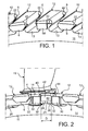
- la figure 3 représente une vue en perspective d'une portion de disque de rotor, adapté pour un dispositif d'immobilisation en rotation d'un anneau de rétention d'aubes mobiles, conformément à l'invention ;
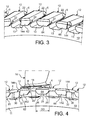
- la figure 4 représente une vue en perspective d'un dispositif d'immobilisation en rotation d'un anneau de rétention d'aubes d'un rotor de turbomachine, conformément à l'invention.
- Figure 1, already described, shows a perspective view of a rotor disc portion, adapted for a device for immobilization in rotation of a blade retention ring, according to the prior art;
- FIG. 2, already described, represents a perspective view of an immobilization device in rotation of a blade retention ring of a turbomachine rotor, according to the prior art;
- FIG. 3 represents a perspective view of a rotor disk portion, adapted for a device for immobilizing in rotation a mobile blade retention ring, according to the invention;
- FIG. 4 represents a perspective view of an immobilization device in rotation of a blade retention ring of a turbomachine rotor, according to the invention.
Le dispositif d'immobilisation en rotation selon l'invention, illustré aux figures 3 et 4, ne sera décrit que pour ses différences avec le dispositif d'immobilisation en rotation selon la technique antérieure, illustré aux figures 1 et 2. Sur les figures, des repères identiques désignent des caractéristiques identiques.The immobilization device in rotation according to the invention, illustrated in FIGS. 3 and 4, will only be described for its differences with the immobilization device in rotation according to the prior art, illustrated in FIGS. 1 and 2. identical markers designate identical characteristics.
Pour simplifier la description détaillée qui suit, l'anneau de rétention sera simplement appelé « anneau » et les premier, deuxième et troisième crochets d'immobilisation seront simplement appelés « premier crochet », « deuxième crochet », et « troisième crochet » respectivement.To simplify the detailed description that follows, the retention ring will simply be called "ring" and the first, second and third immobilization hooks will simply be called "First hook", "second hook", and "third hook" respectively.
En se reportant aux figures 3 et 4, un disque 10 d'un rotor comporte des dents 12 qui s'étendent radialement à partir de sa circonférence et sont réparties sur cette circonférence. L'espace entre deux dents 12 successives forme une alvéole 13 orientée axialement dans laquelle est inséré un pied 14 d'une aube 16. Ces deux dents 12 successives ont des formes et des dimensions qui permettent de contenir circonférentiellement et radialement l'aube 16 installée entre elles dans l'alvéole 13.Referring to Figures 3 and 4, a
Les dents 12 ont une partie en saillie 4 qui dépasse du disque 10 suivant la direction axiale vers l'amont, et/ou une partie en saillie 4 qui dépasse du disque 10 suivant la direction axiale vers l'aval. Dans chaque partie en saillie 4 est ménagée une gorge élémentaire s'ouvrant radialement vers l'intérieur, l'extrémité libre de chaque partie en saillie 4 au-delà de la gorge élémentaire par rapport au corps de disque 11 formant un crochet 6 orienté radialement vers l'intérieur. Chaque gorge élémentaire possède deux parois dont une paroi interne la plus proche du disque de rotor 10 et une paroi externe la plus éloignée du disque de rotor 10.The
La succession des gorges élémentaires forme une gorge 22, discontinue, dans laquelle est disposé un anneau 20. L'anneau 20 dans la gorge 22 constitue une butée axiale qui permet d'empêcher un déplacement axial des aubes 16. Pour faciliter son installation dans la gorge 22, cet anneau 20 est ouvert par une fente 24 qui sépare ses deux extrémités 26 l'une de l'autre.The succession of elementary grooves forms a
L'anneau 20 comporte deux taquets 30 positionnés sur une même face de celui-ci, sur la face opposée à sa face en regard du disque de rotor 10, dans l'exemple illustré à la figure 2.The
De préférence, chaque taquet 302, 304 est réalisé de la manière suivante. On réalise deux découpes sur l'anneau 20, de manière à retirer un secteur d'anneau ayant une dimension donnée suivant la direction circonférentielle dudit anneau 20 et la même dimension que le reste de l'anneau 20 suivant la direction axiale de celui-ci. On remplace le secteur retiré par une pièce ayant la même dimension suivant la direction axiale et la même dimension suivant la direction circonférentielle, mais ayant une épaisseur plus importante. Cette pièce est fixée au reste de l'anneau 20 par soudage de manière à reconstituer un anneau 20 fermé. Puis on usine le taquet 302, 304 dans ladite pièce d'épaisseur plus importante que le reste de l'anneau 20. Un tel mode opératoire permet d'effectuer un usinage précis des taquets 302, 304, en assurant leurs dimensions et leur position sur l'anneau 20.Preferably, each cleat 302, 304 is made in the following manner. Two cuts are made on the
La fente 24 est réalisée sur l'anneau 20 après la réalisation des deux taquets 30. Elle est positionnée de telle manière que les deux taquets 30 soient disposés vers l'une des extrémités 26 de l'anneau 20, de part et d'autre de la fente 24, à une distance déterminée de celle-ci. De préférence, les deux taquets 30 sont espacés l'un de l'autre d'un écart angulaire au moins égal à trois fois le pas angulaire des aubes 16. Ce pas angulaire est défini comme l'écart angulaire entre les plans médians de deux alvéoles 13 successives.The
Chaque taquet 30 comporte une face de contact 32 orientée du côté de la fente 24 de l'anneau 20.Each
Parmi les crochets 6 se trouvent successivement un premier crochet 62, un deuxième crochet 64 et un troisième crochet 66.Among the
Le deuxième crochet 64 a une géométrie similaire à la géométrie des crochets 6 de la technique antérieure.The
Le premier crochet 62 et le troisième crochet 66 ont une géométrie modifiée par rapport celle des crochets 6. Chacun des premier et troisième crochets 62, 66 présente une face frontale 142 qui est la face de sa surface libre, et une face latérale 144 qui est sensiblement perpendiculaire à la face frontale 142. La face latérale 144 du premier crochet 62, respectivement du troisième crochet 66, s'étend depuis la face frontale 142 dudit crochet 62, 66, jusqu'à la paroi interne de la gorge élémentaire dudit crochet 62, 66. De préférence, la face latérale 144 du premier crochet 62 est obtenue par usinage, sur son côté latéral qui est opposé à son côté latéral qui est en regard du troisième crochet 66. De manière analogue, la face latérale 144 du troisième crochet 66 est obtenue par usinage sur son côté latéral qui est opposé à son côté latéral qui est en regard du premier crochet 62.The
En d'autres termes, chacune des dents 12 correspondantes se termine par un crochet 62, 66 qui présente une face latérale 144 sur son côté opposé à son côté en regard de l'autre crochet 66, 62, ladite face latérale 144 étant circonférentiellement en retrait.In other words, each of the corresponding
Sur l'exemple illustré à la figure 2, les faces latérales 144 sont orientées selon un plan radial du disque de rotor 10.In the example illustrated in FIG. 2, the lateral faces 144 are oriented in a radial plane of the
La position des deux taquets 30 sur l'anneau 20 est établie de manière appropriée, de préférence en fonction des dimensions et distances des crochets 62, 64, 66 du disque de rotor 10. Cette position peut être définie par leurs distances respectives par rapport aux extrémités 26 respectives de l'anneau 20 ou par l'écart angulaire qui les sépare. Pour des raisons de facilité de fabrication, il est préféré, mais non nécessaire, que les deux taquets 30 soient disposés de manière symétrique de part et d'autre de la fente 24.The position of the two
Avec une position relative appropriée des deux taquets 30 sur l'anneau 20, lorsque l'anneau 20 est mis en place dans la gorge 22, la face de contact 32 de l'un des taquets 30 se trouve en butée contre la face latérale 144 du premier crochet 62, et la face de contact 32 de l'autre taquet 30 se trouve en butée contre la face latérale 144 du troisième crochet 66. Les faces latérales 144 sont des faces de blocage respectives du premier crochet 62 et du troisième crochet 66, qui coopèrent avec les faces de contact 32 respectives des deux taquets 30 de l'anneau 20. Les deux extrémités 26 de l'anneau 20 et la fente 24 se trouvent alors sous le deuxième crochet 64.With an appropriate relative position of the two
L'anneau 20 est ainsi empêché de tourner dans la gorge 22. Par suite, l'anneau 20 ne peut pas s'échapper de la gorge 22 lors du fonctionnement de la turbomachine. Il s'ensuit que les aubes 16 ne peuvent s'échapper suivant la direction axiale de l'alvéole 13 dans laquelle elles sont insérées.The
L'invention qui vient d'être décrite permet donc d'empêcher l'anneau 20 de tourner dans la gorge 22. Elle présente l'avantage que la fente 24 de l'anneau 20 se trouve positionnée sous un crochet et non pas entre deux crochets. De plus, la fente 24 se trouve positionnée sous le deuxième crochet 64, qui ne présente pas de face latérale en retrait, et possède donc une largeur DD qui n'est pas réduite comme pouvait l'être la largeur D du crochet 60 du dispositif d'immobilisation de la technique antérieure. Par suite, les risques de sortie des extrémités de l'anneau 20 hors de la gorge 22 sont réduits.The invention which has just been described thus makes it possible to prevent the
Avec le dispositif d'immobilisation en rotation de l'anneau selon l'invention, la fonction d'immobilisation proprement dite (par mise en butée des faces de contact 32 des taquets contre les faces de blocage 144 des premier et troisième crochets 62, 66) et la fonction de recouvrement de la fente 24 ne sont pas assurées par un seul crochet de disque comme c'était le cas avec le dispositif d'immobilisation de la technique antérieure.With the immobilization device in rotation of the ring according to the invention, the actual immobilization function (by abutting the contact faces 32 of the catches against the locking faces 144 of the first and
L'invention n'est pas limitée au mode de réalisation qui vient d'être décrit. Sur l'exemple illustré à la figure 4, la fente 24 est perpendiculaire à la direction circonférentielle de l'anneau 20, mais elle pourrait être oblique, sans sortir du cadre de l'invention.The invention is not limited to the embodiment which has just been described. On the example illustrated in Figure 4, the
Sur l'exemple illustré aux figures 3 et 4, les faces de blocage sont orientées selon une direction radiale du disque de rotor 10, mais elles pourraient être orientées selon une direction oblique par rapport à une direction radiale du disque de rotor 10, sans sortir du cadre de l'invention.In the example illustrated in FIGS. 3 and 4, the locking faces are oriented in a radial direction of the
Sur l'exemple illustré aux figures 3 et 4, les alvéoles 13 dans lesquelles sont insérés les pieds 14 des aubes 16 sont orientées axialement, mais l'invention s'applique également aux configurations dans lesquelles la direction des alvéoles forme un angle avec la direction axiale de la turbomachine.In the example illustrated in FIGS. 3 and 4, the
Claims (10)
ledit disque de rotor (10) étant muni de crochets (6, 62, 64, 66) répartis sur sa circonférence et définissant une gorge (22) pour recevoir ledit anneau de rétention (20), dont un premier crochet d'immobilisation (62), un deuxième crochet d'immobilisation (64) et un troisième crochet d'immobilisation (66) successifs, ledit deuxième crochet d'immobilisation (64) étant situé entre lesdits premier et troisième crochets d'immobilisation (62, 66), et ledit anneau de rétention (20) étant muni d'une fente (24), et de deux taquets (30) disposés sur une face de celui-ci de chaque côté de ladite fente (24),
caractérisé en ce que la position desdits taquets (30) sur ledit anneau de rétention (20) est telle que, lorsque ledit anneau de rétention (20) est en place dans ladite gorge (22), lesdits deux taquets (30) sont en butée respectivement contre ledit premier crochet d'immobilisation (62) et contre ledit troisième crochet d'immobilisation (66), et ladite fente (24) est recouverte par ledit deuxième crochet d'immobilisation (64).Device for immobilization in rotation of a retaining ring (20) of vanes (16) on a rotor disc (10) of a turbomachine in a substantially axial direction of said turbomachine,
said rotor disk (10) being provided with circumferentially-spaced hooks (6, 62, 64, 66) defining a groove (22) for receiving said retaining ring (20), including a first immobilizing hook (62); a second immobilization hook (64) and a third immobilization hook (66) in succession, said second immobilization hook (64) being located between said first and third immobilizing hooks (62, 66), and said retention ring (20) being provided with a slot (24), and two catches (30) disposed on one side thereof on each side of said slot (24),
characterized in that the position of said catches (30) on said retaining ring (20) is such that, when said retaining ring (20) is in place in said groove (22), said two catches (30) abut respectively against said first immobilization hook (62) and against said third immobilization hook (66), and said slot (24) is covered by said second immobilization hook (64).
comportant un anneau de rétention (20) muni d'une fente (24), et comportant un disque de rotor (10) muni de crochets (6, 62, 64, 66) répartis sur sa circonférence et définissant une gorge (22) pour la réception dudit anneau de rétention (20),
caractérisé en ce que ledit disque de rotor (10) comporte un premier crochet d'immobilisation (62), un deuxième crochet d'immobilisation (64) et un troisième crochet d'immobilisation (66) successifs,
en ce que ledit anneau de rétention (20) comporte deux taquets (30) disposés sur une face de celui-ci de chaque côté de ladite fente (24),
et en ce que la position desdits taquets (30) sur ledit anneau de rétention (20) est telle que, lorsque ledit anneau de rétention (20) est en place dans ladite gorge (22), lesdits deux taquets (30) sont en butée respectivement contre ledit premier crochet d'immobilisation (62) et contre ledit troisième crochet d'immobilisation (66), et ladite fente (24) est recouverte par ledit deuxième crochet d'immobilisation (64).Disk / ring assembly (10, 20) of a turbomachine,
having a retention ring (20) provided with a slot (24), and having a rotor disk (10) provided with hooks (6, 62, 64, 66) distributed around its circumference and defining a groove (22) for receiving said retention ring (20),
characterized in that said rotor disk (10) has a first immobilization hook (62), a second immobilization hook (64) and a third immobilization hook (66) in succession,
in that said retaining ring (20) has two tabs (30) disposed on one side thereof on each side of said slot (24),
and in that the position of said catches (30) on said retaining ring (20) is such that, when said retaining ring (20) is in place in said groove (22), said two catches (30) abut respectively against said first immobilization hook (62) and against said third immobilization hook (66), and said slot (24) is covered by said second immobilization hook (64).
Applications Claiming Priority (1)
| Application Number | Priority Date | Filing Date | Title |
|---|---|---|---|
| FR0552636A FR2890105A1 (en) | 2005-08-31 | 2005-08-31 | Retention ring immobilization device for e.g. engine of aircraft, has stops positioned such that stops are stopped respectively against immobilization hooks, and slot covered by other hook when retention ring is placed in groove |
Publications (3)
| Publication Number | Publication Date |
|---|---|
| EP1760259A2 true EP1760259A2 (en) | 2007-03-07 |
| EP1760259A3 EP1760259A3 (en) | 2007-08-01 |
| EP1760259B1 EP1760259B1 (en) | 2008-10-15 |
Family
ID=36390217
Family Applications (1)
| Application Number | Title | Priority Date | Filing Date |
|---|---|---|---|
| EP06119582A Active EP1760259B1 (en) | 2005-08-31 | 2006-08-25 | Locking apparatus for an axial retention ring of a blade |
Country Status (6)
| Country | Link |
|---|---|
| US (1) | US7540714B1 (en) |
| EP (1) | EP1760259B1 (en) |
| CA (1) | CA2558028C (en) |
| DE (1) | DE602006003156D1 (en) |
| FR (1) | FR2890105A1 (en) |
| RU (1) | RU2413847C2 (en) |
Cited By (6)
| Publication number | Priority date | Publication date | Assignee | Title |
|---|---|---|---|---|
| CN101457657B (en) * | 2008-12-30 | 2010-12-29 | 东方电气集团东方汽轮机有限公司 | Axial positioning structure for firtree type blade root and blade |
| FR2974142A1 (en) * | 2011-04-14 | 2012-10-19 | Snecma | Immobilization device for ring used for retaining radial blade on disc of rotor of turboshaft engine, has stop including support face that is tilted relative to axial median plane of stop such that face is directed radially toward outside |
| FR2989992A1 (en) * | 2012-04-27 | 2013-11-01 | Snecma | Device for immobilizing rotation of retention ring of blade on rotor disk of aircraft's engine, has ring whose portion is arranged such that edge is formed at bottom of groove of hook to avoid contact between upper edge of ring and bottom |
| FR3000763A1 (en) * | 2013-01-04 | 2014-07-11 | Snecma | ROTOR DISC WITH A PLURALITY OF HOOKS |
| US9129390B2 (en) | 2007-06-19 | 2015-09-08 | Agfa Healthcare Nv | Method of segmenting anatomic entities in 3D digital medical images |
| EP2918785A1 (en) * | 2014-03-12 | 2015-09-16 | Rolls-Royce plc | A bladed rotor |
Families Citing this family (4)
| Publication number | Priority date | Publication date | Assignee | Title |
|---|---|---|---|---|
| FR2955904B1 (en) * | 2010-02-04 | 2012-07-20 | Snecma | TURBOMACHINE BLOWER |
| US8753090B2 (en) * | 2010-11-24 | 2014-06-17 | Rolls-Royce Corporation | Bladed disk assembly |
| US8864471B2 (en) | 2011-08-12 | 2014-10-21 | Hamilton Sundstrand Corporation | Gas turbine rotor with purge blades |
| EP4230843A1 (en) * | 2022-02-17 | 2023-08-23 | Siemens Energy Global GmbH & Co. KG | A rotor arrangement for a rotor of a gas turbine |
Citations (5)
| Publication number | Priority date | Publication date | Assignee | Title |
|---|---|---|---|---|
| US4221542A (en) * | 1977-12-27 | 1980-09-09 | General Electric Company | Segmented blade retainer |
| US5320492A (en) * | 1992-07-22 | 1994-06-14 | Societe Nationale D'etude Et De Construction De Moteurs D'aviation "Snecma" | Sealing and retaining device for a rotor notched with pin settings receiving blade roots |
| FR2729709A1 (en) * | 1995-01-25 | 1996-07-26 | Snecma | Turbine rotor seal and retainer |
| US6234756B1 (en) * | 1998-10-26 | 2001-05-22 | Allison Advanced Development Company | Segmented ring blade retainer |
| EP1443179A2 (en) * | 2003-01-30 | 2004-08-04 | ROLLS-ROYCE plc | A rotor and a retaining plate for the same |
Family Cites Families (3)
| Publication number | Priority date | Publication date | Assignee | Title |
|---|---|---|---|---|
| US4033705A (en) * | 1976-04-26 | 1977-07-05 | The United States Of America As Represented By The Administrator Of The National Aeronautics And Space Administration | Blade retainer assembly |
| FR2603333B1 (en) * | 1986-09-03 | 1990-07-20 | Snecma | TURBOMACHINE ROTOR COMPRISING A MEANS OF AXIAL LOCKING AND SEALING OF BLADES MOUNTED IN AXIAL PINS OF THE DISC AND MOUNTING METHOD |
| FR2890104A1 (en) * | 2005-08-31 | 2007-03-02 | Snecma | Rotation blocking device for use in turbomachine rotor of aircraft engine, has ring with split and set of cleat, which is arranged on ring and placed in groove of rotor disk that includes blocking hook with check face |
-
2005
- 2005-08-31 FR FR0552636A patent/FR2890105A1/en not_active Withdrawn
-
2006
- 2006-08-24 US US11/466,994 patent/US7540714B1/en active Active
- 2006-08-25 EP EP06119582A patent/EP1760259B1/en active Active
- 2006-08-25 DE DE602006003156T patent/DE602006003156D1/en active Active
- 2006-08-28 CA CA2558028A patent/CA2558028C/en active Active
- 2006-08-30 RU RU2006131299/06A patent/RU2413847C2/en active
Patent Citations (5)
| Publication number | Priority date | Publication date | Assignee | Title |
|---|---|---|---|---|
| US4221542A (en) * | 1977-12-27 | 1980-09-09 | General Electric Company | Segmented blade retainer |
| US5320492A (en) * | 1992-07-22 | 1994-06-14 | Societe Nationale D'etude Et De Construction De Moteurs D'aviation "Snecma" | Sealing and retaining device for a rotor notched with pin settings receiving blade roots |
| FR2729709A1 (en) * | 1995-01-25 | 1996-07-26 | Snecma | Turbine rotor seal and retainer |
| US6234756B1 (en) * | 1998-10-26 | 2001-05-22 | Allison Advanced Development Company | Segmented ring blade retainer |
| EP1443179A2 (en) * | 2003-01-30 | 2004-08-04 | ROLLS-ROYCE plc | A rotor and a retaining plate for the same |
Cited By (8)
| Publication number | Priority date | Publication date | Assignee | Title |
|---|---|---|---|---|
| US9129390B2 (en) | 2007-06-19 | 2015-09-08 | Agfa Healthcare Nv | Method of segmenting anatomic entities in 3D digital medical images |
| CN101457657B (en) * | 2008-12-30 | 2010-12-29 | 东方电气集团东方汽轮机有限公司 | Axial positioning structure for firtree type blade root and blade |
| FR2974142A1 (en) * | 2011-04-14 | 2012-10-19 | Snecma | Immobilization device for ring used for retaining radial blade on disc of rotor of turboshaft engine, has stop including support face that is tilted relative to axial median plane of stop such that face is directed radially toward outside |
| FR2989992A1 (en) * | 2012-04-27 | 2013-11-01 | Snecma | Device for immobilizing rotation of retention ring of blade on rotor disk of aircraft's engine, has ring whose portion is arranged such that edge is formed at bottom of groove of hook to avoid contact between upper edge of ring and bottom |
| FR3000763A1 (en) * | 2013-01-04 | 2014-07-11 | Snecma | ROTOR DISC WITH A PLURALITY OF HOOKS |
| US9689278B2 (en) | 2013-01-04 | 2017-06-27 | Snecma | Rotor disk including a plurality of hooks |
| EP2918785A1 (en) * | 2014-03-12 | 2015-09-16 | Rolls-Royce plc | A bladed rotor |
| US10138741B2 (en) | 2014-03-12 | 2018-11-27 | Rolls-Royce Plc | Bladed rotor |
Also Published As
| Publication number | Publication date |
|---|---|
| US20090136349A1 (en) | 2009-05-28 |
| EP1760259B1 (en) | 2008-10-15 |
| FR2890105A1 (en) | 2007-03-02 |
| DE602006003156D1 (en) | 2008-11-27 |
| RU2006131299A (en) | 2008-03-10 |
| CA2558028A1 (en) | 2007-02-28 |
| US7540714B1 (en) | 2009-06-02 |
| RU2413847C2 (en) | 2011-03-10 |
| CA2558028C (en) | 2013-08-13 |
| EP1760259A3 (en) | 2007-08-01 |
Similar Documents
| Publication | Publication Date | Title |
|---|---|---|
| EP1760259B1 (en) | Locking apparatus for an axial retention ring of a blade | |
| EP1760258B1 (en) | Locking appartus for an axial retention ring of a blade | |
| CA2456014C (en) | Assembly to retain an annular flange against a radial surface of a disk | |
| EP1584794B1 (en) | Disk of a turbomachine rotor with an axial retention device for the blades | |
| CA2644335C (en) | Turbine or compressor stage, in particular of a turbine engine | |
| EP2839117B1 (en) | Turbine stage for a turbomachine | |
| EP1507960B1 (en) | Bladed rotor wheel of a turbomachine | |
| CA2598532C (en) | Turbomachine rotor blade | |
| EP0017534A1 (en) | Exchangeable sealing for the stator segment of a turbomachine | |
| FR2911632A1 (en) | Fan rotor disc for jet engine of aircraft, has axial grooves mounting and retaining vane roots, and deformable zones radially located outside grooves, where zones are placed at rear end of grooves | |
| FR2918409A1 (en) | Rotating part i.e. fan, for turbine engine of aircraft, has blade with circumferential projection detected in continuity of adjacent platform forming sector, where projection participates in definition of inter-blade surface | |
| CA2644326C (en) | Turbojet turbine or compressor stage | |
| FR2729709A1 (en) | Turbine rotor seal and retainer | |
| EP2060744B1 (en) | Stage of a turbine or turbomachine compressor | |
| EP3433469B1 (en) | Platform, fan assembly and fan | |
| EP3444439A1 (en) | Turbine for turbine engine comprising blades with a root having an exapnding form in axial direction | |
| FR2995036A1 (en) | BLOWER ROTOR, ESPECIALLY FOR A TURBOMACHINE | |
| FR3001505A1 (en) | AXIAL BLOCKING DEVICE OF A MOBILE PART WITH RESPECT TO A REFERENCE PART | |
| WO2012110735A1 (en) | Device for blocking vanes around a periphery, for a turbomachine, to be deployed radially by a rotational movement of a member of the device | |
| FR3053384A1 (en) | FIXING ASSEMBLY OF A DISTRIBUTOR TO A STRUCTURAL ELEMENT OF A TURBOMACHINE | |
| FR3081520A1 (en) | IMPROVED TURBOMACHINE BLOWER DISK | |
| FR2974142A1 (en) | Immobilization device for ring used for retaining radial blade on disc of rotor of turboshaft engine, has stop including support face that is tilted relative to axial median plane of stop such that face is directed radially toward outside | |
| FR3041381A1 (en) | EXHAUST CASE ASSEMBLY AND ANCHORED ELEMENT MOUNTED BY BAIONNETTE | |
| FR3121706A1 (en) | FLASHING TABS FOR TURBOMACHINE ROTOR BLADE FOOT | |
| FR2989992A1 (en) | Device for immobilizing rotation of retention ring of blade on rotor disk of aircraft's engine, has ring whose portion is arranged such that edge is formed at bottom of groove of hook to avoid contact between upper edge of ring and bottom |
Legal Events
| Date | Code | Title | Description |
|---|---|---|---|
| PUAI | Public reference made under article 153(3) epc to a published international application that has entered the european phase |
Free format text: ORIGINAL CODE: 0009012 |
|
| AK | Designated contracting states |
Kind code of ref document: A2 Designated state(s): AT BE BG CH CY CZ DE DK EE ES FI FR GB GR HU IE IS IT LI LT LU LV MC NL PL PT RO SE SI SK TR |
|
| AX | Request for extension of the european patent |
Extension state: AL BA HR MK YU |
|
| PUAL | Search report despatched |
Free format text: ORIGINAL CODE: 0009013 |
|
| AK | Designated contracting states |
Kind code of ref document: A3 Designated state(s): AT BE BG CH CY CZ DE DK EE ES FI FR GB GR HU IE IS IT LI LT LU LV MC NL PL PT RO SE SI SK TR |
|
| AX | Request for extension of the european patent |
Extension state: AL BA HR MK YU |
|
| RIC1 | Information provided on ipc code assigned before grant |
Ipc: F01D 5/32 20060101AFI20070627BHEP Ipc: F01D 5/30 20060101ALI20070627BHEP Ipc: F01D 5/02 20060101ALI20070627BHEP |
|
| 17P | Request for examination filed |
Effective date: 20070906 |
|
| GRAP | Despatch of communication of intention to grant a patent |
Free format text: ORIGINAL CODE: EPIDOSNIGR1 |
|
| AKX | Designation fees paid |
Designated state(s): DE FR GB |
|
| GRAS | Grant fee paid |
Free format text: ORIGINAL CODE: EPIDOSNIGR3 |
|
| GRAA | (expected) grant |
Free format text: ORIGINAL CODE: 0009210 |
|
| AK | Designated contracting states |
Kind code of ref document: B1 Designated state(s): DE FR GB |
|
| REG | Reference to a national code |
Ref country code: GB Ref legal event code: FG4D Free format text: NOT ENGLISH |
|
| REF | Corresponds to: |
Ref document number: 602006003156 Country of ref document: DE Date of ref document: 20081127 Kind code of ref document: P |
|
| PLBE | No opposition filed within time limit |
Free format text: ORIGINAL CODE: 0009261 |
|
| STAA | Information on the status of an ep patent application or granted ep patent |
Free format text: STATUS: NO OPPOSITION FILED WITHIN TIME LIMIT |
|
| 26N | No opposition filed |
Effective date: 20090716 |
|
| REG | Reference to a national code |
Ref country code: FR Ref legal event code: PLFP Year of fee payment: 11 |
|
| REG | Reference to a national code |
Ref country code: FR Ref legal event code: PLFP Year of fee payment: 12 |
|
| REG | Reference to a national code |
Ref country code: FR Ref legal event code: CD Owner name: SAFRAN AIRCRAFT ENGINES Effective date: 20170713 |
|
| REG | Reference to a national code |
Ref country code: FR Ref legal event code: PLFP Year of fee payment: 13 |
|
| PGFP | Annual fee paid to national office [announced via postgrant information from national office to epo] |
Ref country code: GB Payment date: 20230720 Year of fee payment: 18 |
|
| PGFP | Annual fee paid to national office [announced via postgrant information from national office to epo] |
Ref country code: FR Payment date: 20230720 Year of fee payment: 18 Ref country code: DE Payment date: 20230720 Year of fee payment: 18 |