EP1759576B1 - Lawnmower - Google Patents
Lawnmower Download PDFInfo
- Publication number
- EP1759576B1 EP1759576B1 EP06253021A EP06253021A EP1759576B1 EP 1759576 B1 EP1759576 B1 EP 1759576B1 EP 06253021 A EP06253021 A EP 06253021A EP 06253021 A EP06253021 A EP 06253021A EP 1759576 B1 EP1759576 B1 EP 1759576B1
- Authority
- EP
- European Patent Office
- Prior art keywords
- grass
- lawnmower
- carrier
- box
- deck
- Prior art date
- Legal status (The legal status is an assumption and is not a legal conclusion. Google has not performed a legal analysis and makes no representation as to the accuracy of the status listed.)
- Not-in-force
Links
- 241001494496 Leersia Species 0.000 claims description 8
- 230000000295 complement effect Effects 0.000 claims description 2
- 244000025254 Cannabis sativa Species 0.000 description 3
- 238000005452 bending Methods 0.000 description 1
- 238000012986 modification Methods 0.000 description 1
- 230000004048 modification Effects 0.000 description 1
Images



Classifications
-
- A—HUMAN NECESSITIES
- A01—AGRICULTURE; FORESTRY; ANIMAL HUSBANDRY; HUNTING; TRAPPING; FISHING
- A01D—HARVESTING; MOWING
- A01D43/00—Mowers combined with apparatus performing additional operations while mowing
- A01D43/06—Mowers combined with apparatus performing additional operations while mowing with means for collecting, gathering or loading mown material
- A01D43/063—Mowers combined with apparatus performing additional operations while mowing with means for collecting, gathering or loading mown material in or into a container carried by the mower; Containers therefor
-
- A—HUMAN NECESSITIES
- A01—AGRICULTURE; FORESTRY; ANIMAL HUSBANDRY; HUNTING; TRAPPING; FISHING
- A01D—HARVESTING; MOWING
- A01D43/00—Mowers combined with apparatus performing additional operations while mowing
- A01D43/06—Mowers combined with apparatus performing additional operations while mowing with means for collecting, gathering or loading mown material
- A01D43/063—Mowers combined with apparatus performing additional operations while mowing with means for collecting, gathering or loading mown material in or into a container carried by the mower; Containers therefor
- A01D43/0635—Mowers combined with apparatus performing additional operations while mowing with means for collecting, gathering or loading mown material in or into a container carried by the mower; Containers therefor with emptying means
-
- A—HUMAN NECESSITIES
- A01—AGRICULTURE; FORESTRY; ANIMAL HUSBANDRY; HUNTING; TRAPPING; FISHING
- A01D—HARVESTING; MOWING
- A01D75/00—Accessories for harvesters or mowers
- A01D75/18—Safety devices for parts of the machines
-
- A—HUMAN NECESSITIES
- A01—AGRICULTURE; FORESTRY; ANIMAL HUSBANDRY; HUNTING; TRAPPING; FISHING
- A01D—HARVESTING; MOWING
- A01D2101/00—Lawn-mowers
-
- A—HUMAN NECESSITIES
- A01—AGRICULTURE; FORESTRY; ANIMAL HUSBANDRY; HUNTING; TRAPPING; FISHING
- A01D—HARVESTING; MOWING
- A01D43/00—Mowers combined with apparatus performing additional operations while mowing
- A01D43/06—Mowers combined with apparatus performing additional operations while mowing with means for collecting, gathering or loading mown material
- A01D43/077—Mowers combined with apparatus performing additional operations while mowing with means for collecting, gathering or loading mown material with auxiliary means, e.g. fans, for transporting the mown crop
- A01D43/0775—Mowers combined with apparatus performing additional operations while mowing with means for collecting, gathering or loading mown material with auxiliary means, e.g. fans, for transporting the mown crop for airborne lawn-mowers
Definitions
- This invention relates to a lawnmower having a grass-box located behind the cutting chamber of the lawnmower (see e.g. EP 0 253 231 ).
- a known lawnmower has a deck defining a cutting chamber which houses a cutter. Grass cut by the cutter it is rejected rearwardly together with a stream of air generated by movement of the cutter. This stream of air and cut grass leaves the cutting chamber, via a chute, and is directed into the grass-box which is a positioned behind the cutting chamber.
- This type of lawnmower is known as a rear-collect lawnmower.
- a conventional rear-collect lawnmower has a lift-off grass-box which is hung by its front top edge to the deck of the lawnmower.
- a sprung safety flap is used to cover the exit chute when the grass-box is not fitted to the lawnmower.
- This flap is usually sprung from its top edge, requiring the user to hold the flap in the upper position with one hand whilst fitting the grass-box with the other hand. This is an awkward operation, and requires lots of bending and twisting by the user and two-handed operation.
- An aim of the invention is to provide a rear-collect lawnmower whose grass-box can be fitted and removed in a simple one-handed operation.
- the present invention provides a lawnmower comprising a deck defining a cutting chamber open to ground datum, an exit aperture for directing cut grass away from the cutting chamber, and a grass-box having an entry opening for admitting cut grass, wherein the grass-box is detachably mounted on, and supported by a carrier, and the carrier is pivotally mounted on the deck for movement between a first position, in which the grass-box entry opening is in alignment with the exit aperture, and a second position, in which the grass-box entry opening is out of alignment with the exit aperture and the carrier guards the exit aperture.
- the exit aperture is formed in the deck, and a chute leads from a cutting chamber exit to the exit aperture.
- the carrier has a base plate and two side plates.
- each of the side plates is provided with an inwardly-projecting flange, and the side walls of the grass-box are provided with complementary grooves, the flanges and the grooves constituting means for detachably mounting the grass-box on the carrier.
- the flanges taper along their lengths.
- the arrangement is such that the grass-box is locked to the carrier in all positions but said second position.
- the carrier is pivotally attached to the deck by two pairs of links, one pair at each side of the lawnmower, each link of each pair being pivotally attached to both the deck and the carrier at opposite ends thereof.
- one link of each pair is longer than the other link of that pair, and each said one link is positioned beneath each said other link.
- Figure 1 shows a wheeled rotary lawnmower having a deck 1 supported by wheels 2.
- the deck 1 defines a cutting chamber (not shown) which is open to ground datum.
- a cutting blade (not shown) is mounted in the cutting chamber for rotation about a substantially vertical axis.
- a grass-box 3 is mounted on a carrier 4 attached to the deck 1 by means of a respective pair of links (only one of which pair of links can be seen in the drawings) at each side of the deck.
- Each pair of links is constituted by a first, upper link 5, and a second, lower link 6.
- Each link 5 is pivotally attached to the deck 1 by a pivot point 5a, and to the carrier 4 by a pivot point 5b.
- each link 6 is pivotally attached to the deck 1 by a pivot point 6a, and to the carrier 4 by a pivot point 6b.
- the carrier 4 has a base plate 4a and a pair of side plates 4b.
- a respective tapered flange 7 is formed on the inside of each of the side plates 4b, the flanges complementing tapered grooves 3a formed in the sidewalls of the grass-box 3.
- the grass-box 3 can, therefore, be fixed to the carrier 4 by the inter-engagement of the grooves 3a and the flanges 4b.
- the cutting blade may be formed with up-turned tips, so that rotation of the cutting blade generates an air inflow which carries grass cut by the blade towards a chute (not shown) which connects the cutting chamber to the rear of the deck 1.
- the grass-box 3 has an open front end 3b (as can be seen in Figures 2 to 4 ), through which the cut grass can enter the grass-box from the cutting chamber.
- the carrier 4 When the lawnmower is not to be used, the carrier 4 is in the position shown in Figure 4 , in which the base plate 4a of the carrier 4 overlies the rear of the deck 1. The base plate 4a thus acts as a safety flap covering the exit of the chute. With the carrier 4 in this position, the grass-box 3 can be fixed to the carrier by the engagement of the grooves 3a with the flanges 7. The carrier 4 can then be pivoted through substantially 90° to the position shown in Figure 1 , in which the grass-box 3 is in the working position with its open front end 3b overlying the exit of the chute.
- the carrier 4 When the grass-box 3 is full, the carrier 4 is pivoted from the position shown in Figure 1 to the position are shown in Figure 3 , via the position shown in Figure 2 .
- the grass-box 3 can then be removed from the carrier 4, for emptying, by disengaging the grooves 3a from the flanges 7.
- the empty grass-box 3 can then be re-mounted on the carrier 4 by re-engaging the grooves 3a with the flanges 7.
- the engagement between the tapered grooves 3a and the tapered flanges 7 is a positive location, so that the grass-box 3 cannot be removed from of the carrier 4 until the carrier is in the position shown in Figure 3 .
- a four-bar link system constituted by the links, the carrier and the deck.
- the links 5, 6 are of different lengths, they provide a locus of movement such that the grass-box 3 is held, in the working position shown in Figure 1 , against the rear of the deck 1. In this configuration, the grass-box 3 is positioned for optimum grass collection.
- the open end 3b of the grass-box 3 is positioned substantially horizontally, so that cut grass is unlikely to fall out of the grass-box when the grass-box is removed for emptying.
- a spring (not shown) is provided to bias the carrier 4 towards the position shown in Figure 3 , that is to say towards the position where the base plate 4a acts as a safety flap, and the grass-box 3 is positioned for removal from the carrier 4.
- This spring biasing of the carrier 4 ensures that the base plate 4a is held firmly against the rear of the deck 1 when the lawnmower is not in use.
- a catch could be provided to hold the carrier 4 in this position.
Landscapes
- Life Sciences & Earth Sciences (AREA)
- Environmental Sciences (AREA)
- Harvester Elements (AREA)
Description
- This invention relates to a lawnmower having a grass-box located behind the cutting chamber of the lawnmower (see e.g.
EP 0 253 231 ). - A known lawnmower has a deck defining a cutting chamber which houses a cutter. Grass cut by the cutter it is rejected rearwardly together with a stream of air generated by movement of the cutter. This stream of air and cut grass leaves the cutting chamber, via a chute, and is directed into the grass-box which is a positioned behind the cutting chamber. This type of lawnmower is known as a rear-collect lawnmower.
- A conventional rear-collect lawnmower has a lift-off grass-box which is hung by its front top edge to the deck of the lawnmower. In order to meet legal requirements, a sprung safety flap is used to cover the exit chute when the grass-box is not fitted to the lawnmower. This flap is usually sprung from its top edge, requiring the user to hold the flap in the upper position with one hand whilst fitting the grass-box with the other hand. This is an awkward operation, and requires lots of bending and twisting by the user and two-handed operation.
- An aim of the invention is to provide a rear-collect lawnmower whose grass-box can be fitted and removed in a simple one-handed operation.
- The present invention provides a lawnmower comprising a deck defining a cutting chamber open to ground datum, an exit aperture for directing cut grass away from the cutting chamber, and a grass-box having an entry opening for admitting cut grass, wherein the grass-box is detachably mounted on, and supported by a carrier, and the carrier is pivotally mounted on the deck for movement between a first position, in which the grass-box entry opening is in alignment with the exit aperture, and a second position, in which the grass-box entry opening is out of alignment with the exit aperture and the carrier guards the exit aperture.
- Preferably, the exit aperture is formed in the deck, and a chute leads from a cutting chamber exit to the exit aperture.
In a preferred embodiment, the carrier has a base plate and two side plates. Preferably, each of the side plates is provided with an inwardly-projecting flange, and the side walls of the grass-box are provided with complementary grooves, the flanges and the grooves constituting means for detachably mounting the grass-box on the carrier. - Advantageously, the flanges taper along their lengths.
- Conveniently, the arrangement is such that the grass-box is locked to the carrier in all positions but said second position.
- Preferably, the carrier is pivotally attached to the deck by two pairs of links, one pair at each side of the lawnmower, each link of each pair being pivotally attached to both the deck and the carrier at opposite ends thereof.
- Advantageously, one link of each pair is longer than the other link of that pair, and each said one link is positioned beneath each said other link.
- A lawnmower constructed in accordance with the invention will now be described in greater detail, by way of example, with reference to the drawings, in which:
-
Figure 1 is a perspective view of the lawnmower with its grass-box in a first operating position; -
Figure 2 is a perspective view of the lawnmower with its grass-box in an intermediate position; -
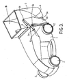
Figure 3 is a perspective view of the lawnmower with its grass-box in a second operating position; and -
Figure 4 is a perspective view of the lawnmower with its grass-box removed. - Referring to the drawings,
Figure 1 shows a wheeled rotary lawnmower having adeck 1 supported bywheels 2. Thedeck 1 defines a cutting chamber (not shown) which is open to ground datum. A cutting blade (not shown) is mounted in the cutting chamber for rotation about a substantially vertical axis. A grass-box 3 is mounted on a carrier 4 attached to thedeck 1 by means of a respective pair of links (only one of which pair of links can be seen in the drawings) at each side of the deck. Each pair of links is constituted by a first,upper link 5, and a second,lower link 6. Eachlink 5 is pivotally attached to thedeck 1 by apivot point 5a, and to the carrier 4 by apivot point 5b. Similarly, eachlink 6 is pivotally attached to thedeck 1 by apivot point 6a, and to the carrier 4 by apivot point 6b. - As best seen in
Figure 4 , the carrier 4 has a base plate 4a and a pair ofside plates 4b. A respective tapered flange 7 is formed on the inside of each of theside plates 4b, the flanges complementingtapered grooves 3a formed in the sidewalls of the grass-box 3. The grass-box 3 can, therefore, be fixed to the carrier 4 by the inter-engagement of thegrooves 3a and theflanges 4b. - The cutting blade may be formed with up-turned tips, so that rotation of the cutting blade generates an air inflow which carries grass cut by the blade towards a chute (not shown) which connects the cutting chamber to the rear of the
deck 1. The grass-box 3 has anopen front end 3b (as can be seen inFigures 2 to 4 ), through which the cut grass can enter the grass-box from the cutting chamber. - When the lawnmower is not to be used, the carrier 4 is in the position shown in
Figure 4 , in which the base plate 4a of the carrier 4 overlies the rear of thedeck 1. The base plate 4a thus acts as a safety flap covering the exit of the chute. With the carrier 4 in this position, the grass-box 3 can be fixed to the carrier by the engagement of thegrooves 3a with the flanges 7. The carrier 4 can then be pivoted through substantially 90° to the position shown inFigure 1 , in which the grass-box 3 is in the working position with itsopen front end 3b overlying the exit of the chute. - When the grass-box 3 is full, the carrier 4 is pivoted from the position shown in
Figure 1 to the position are shown inFigure 3 , via the position shown inFigure 2 . The grass-box 3 can then be removed from the carrier 4, for emptying, by disengaging thegrooves 3a from the flanges 7. The empty grass-box 3 can then be re-mounted on the carrier 4 by re-engaging thegrooves 3a with the flanges 7. The engagement between thetapered grooves 3a and the tapered flanges 7 is a positive location, so that the grass-box 3 cannot be removed from of the carrier 4 until the carrier is in the position shown inFigure 3 . - As the carrier 4 is fixed to the
deck 1 by two pairs oflinks links Figure 1 , against the rear of thedeck 1. In this configuration, the grass-box 3 is positioned for optimum grass collection. When rotated upwardly, to the position shown inFigure 3 , theopen end 3b of the grass-box 3 is positioned substantially horizontally, so that cut grass is unlikely to fall out of the grass-box when the grass-box is removed for emptying. - A spring (not shown) is provided to bias the carrier 4 towards the position shown in
Figure 3 , that is to say towards the position where the base plate 4a acts as a safety flap, and the grass-box 3 is positioned for removal from the carrier 4. This spring biasing of the carrier 4 ensures that the base plate 4a is held firmly against the rear of thedeck 1 when the lawnmower is not in use. Alternatively, or in addition, a catch could be provided to hold the carrier 4 in this position. - It will be apparent that modifications could be made to the lawnmower described above. For example, if the lawnmower is to be used in a non-collect mode, that is to say with the grass-box 3 removed, means would be provided for holding the carrier with the base plate 4a angled away from the rear of the
deck 1, to allow cut grass to exit the cutting chamber and fall to the ground at the rear of the machine. - Although the lawnmower described above is a wheeled rotary lawnmower, it will be apparent that the invention is equally applicable to a hover mower or a cylinder mower.
Claims (8)
- A lawnmower comprising a deck (1) defining a cutting chamber open to ground datum, an exit aperture for directing cut grass away from the cutting chamber , and a grass-box (3) having an entry opening (3b) for admitting cut grass, wherein the grass-box is detachably mounted on, and supported by, a carrier (4), and the carrier is pivotally mounted on the deck for movement between a first position, in which the grass-box entry opening is in alignment with the exit aperture, and second position, in which the grass-box entry opening is out of alignment with the exit aperture and the carrier guards the exit aperture.
- A lawnmower as claimed in claim 1, wherein the exit aperture is formed in the deck, and a chute leads from a cutting chamber exit to the exit aperture.
- A lawnmower as claimed in claim 1 or claim 2, wherein the carrier (4) has a base plate (4a) and two side plates (4b).
- A lawnmower as claimed in claim 3, wherein each of the side plates (4b) is provided with an inwardly-projecting flange (7), and the side walls of the grass-box (3) are provided with complementary grooves (3a), the flanges and the grooves constituting means for detachably mounting the grass-box on the carrier (4).
- A lawnmower as claimed in claim 4, wherein the flanges (7) taper along their lengths.
- A lawnmower as claimed in any one of claims 1 to 5, wherein the arrangement is such that the grass-box (3) is locked to the carrier (4) in all positions but said second position.
- A lawnmower as claimed in any one of claims 1 to 6, wherein the carrier (4) is pivotally attached to the deck (1) by two pairs of links (5, 6), one pair at each side of the lawnmower, each link of each pair being pivotally attached to both the deck and the carrier at opposite ends thereof.
- A lawnmower as claimed in claim 7, wherein one link of each pair is longer than the other link of that pair, and each said one link is positioned beneath each said other link.
Applications Claiming Priority (1)
| Application Number | Priority Date | Filing Date | Title |
|---|---|---|---|
| GB0517726A GB2429624B (en) | 2005-08-31 | 2005-08-31 | Lawnmower |
Publications (3)
| Publication Number | Publication Date |
|---|---|
| EP1759576A2 EP1759576A2 (en) | 2007-03-07 |
| EP1759576A3 EP1759576A3 (en) | 2007-10-24 |
| EP1759576B1 true EP1759576B1 (en) | 2011-06-15 |
Family
ID=35220620
Family Applications (1)
| Application Number | Title | Priority Date | Filing Date |
|---|---|---|---|
| EP06253021A Not-in-force EP1759576B1 (en) | 2005-08-31 | 2006-06-12 | Lawnmower |
Country Status (2)
| Country | Link |
|---|---|
| EP (1) | EP1759576B1 (en) |
| GB (1) | GB2429624B (en) |
Cited By (2)
| Publication number | Priority date | Publication date | Assignee | Title |
|---|---|---|---|---|
| CN103283391A (en) * | 2013-05-24 | 2013-09-11 | 赵延辉 | Mower |
| US9750186B2 (en) | 2015-01-13 | 2017-09-05 | The Toro Company | Walk-behind mower including debris container |
Families Citing this family (2)
| Publication number | Priority date | Publication date | Assignee | Title |
|---|---|---|---|---|
| CN104871719B (en) * | 2014-02-28 | 2017-08-22 | 苏州宝时得电动工具有限公司 | Hay mover |
| US12022773B2 (en) * | 2021-07-21 | 2024-07-02 | Techtronic Cordless Gp | Lawn mower and associated attachment |
Family Cites Families (5)
| Publication number | Priority date | Publication date | Assignee | Title |
|---|---|---|---|---|
| FR2247152A1 (en) * | 1973-10-16 | 1975-05-09 | Bernard Moteurs | Rotary lawn mower with removable grass box - cover for the box pivots down to enclose blades when box is removed |
| JPS62190420U (en) * | 1986-05-24 | 1987-12-03 | ||
| DE8618664U1 (en) * | 1986-07-11 | 1986-11-13 | AL-KO Kober AG, 89359 Kötz | Motorized lawn mower |
| SE458979B (en) * | 1987-12-14 | 1989-05-29 | Dahlmans Klippo Ab | ROTOR GRAY CUTTER WITH GRAAS COLLECTOR |
| JP3703699B2 (en) * | 2000-08-31 | 2005-10-05 | 本田技研工業株式会社 | Lawn mower housing structure |
-
2005
- 2005-08-31 GB GB0517726A patent/GB2429624B/en not_active Expired - Fee Related
-
2006
- 2006-06-12 EP EP06253021A patent/EP1759576B1/en not_active Not-in-force
Cited By (3)
| Publication number | Priority date | Publication date | Assignee | Title |
|---|---|---|---|---|
| CN103283391A (en) * | 2013-05-24 | 2013-09-11 | 赵延辉 | Mower |
| CN103283391B (en) * | 2013-05-24 | 2016-01-13 | 赵延辉 | Mower |
| US9750186B2 (en) | 2015-01-13 | 2017-09-05 | The Toro Company | Walk-behind mower including debris container |
Also Published As
| Publication number | Publication date |
|---|---|
| EP1759576A2 (en) | 2007-03-07 |
| EP1759576A3 (en) | 2007-10-24 |
| GB2429624A (en) | 2007-03-07 |
| GB2429624B (en) | 2008-02-06 |
| GB0517726D0 (en) | 2005-10-12 |
Similar Documents
| Publication | Publication Date | Title |
|---|---|---|
| US5231827A (en) | Lawn and garden chipper shredder vacuum apparatus | |
| US7093415B2 (en) | Lawn mower having adjustable flow control baffle | |
| JP2014060940A (en) | Riding-type lawn mower | |
| EP2039453B1 (en) | Jigsaw | |
| EP1785027B1 (en) | Lawn mower | |
| JP2014060936A (en) | Riding-type lawn mower | |
| EP2499894B1 (en) | Lawnmowers | |
| NO178011B (en) | Grass Cutting Machine | |
| EP1512319A2 (en) | Grass mower | |
| US4478031A (en) | Lawnmowers with rotatable cutting blades | |
| US6694716B1 (en) | Mowing machine chute cleaner apparatus and method | |
| EP1759576A2 (en) | Lawnmower | |
| EP1435194A1 (en) | Trimmer | |
| JP6221898B2 (en) | Riding mower | |
| US20210029875A1 (en) | Lawn mower | |
| CN209749199U (en) | Discharged straw breaking device | |
| US20080307762A1 (en) | Bagging Lawn Mower with Selective Mulch or Discharge Options | |
| JP7077160B2 (en) | Lawn mower | |
| US20030070820A1 (en) | Hinged edger housing having improved internal debris guard and labyrinth perimeter seal | |
| JP5338457B2 (en) | Lawn mower mower deck | |
| JP4838624B2 (en) | lawn mower | |
| US6675566B2 (en) | Tool, such as a lawnmower or the like, particularly for gardening vehicles | |
| JP4951098B2 (en) | Traveling lawn mower | |
| GB2333435A (en) | Rotary lawnmowers | |
| ITVI20090294A1 (en) | PROTECTIVE DEVICE FOR BRUSHCUTTERS AND ITS BRUSH CUTTER |
Legal Events
| Date | Code | Title | Description |
|---|---|---|---|
| PUAI | Public reference made under article 153(3) epc to a published international application that has entered the european phase |
Free format text: ORIGINAL CODE: 0009012 |
|
| AK | Designated contracting states |
Kind code of ref document: A2 Designated state(s): AT BE BG CH CY CZ DE DK EE ES FI FR GB GR HU IE IS IT LI LT LU LV MC NL PL PT RO SE SI SK TR |
|
| AX | Request for extension of the european patent |
Extension state: AL BA HR MK YU |
|
| PUAL | Search report despatched |
Free format text: ORIGINAL CODE: 0009013 |
|
| AK | Designated contracting states |
Kind code of ref document: A3 Designated state(s): AT BE BG CH CY CZ DE DK EE ES FI FR GB GR HU IE IS IT LI LT LU LV MC NL PL PT RO SE SI SK TR |
|
| AX | Request for extension of the european patent |
Extension state: AL BA HR MK YU |
|
| 17P | Request for examination filed |
Effective date: 20080408 |
|
| 17Q | First examination report despatched |
Effective date: 20080514 |
|
| AKX | Designation fees paid |
Designated state(s): DE FR GB |
|
| GRAP | Despatch of communication of intention to grant a patent |
Free format text: ORIGINAL CODE: EPIDOSNIGR1 |
|
| GRAS | Grant fee paid |
Free format text: ORIGINAL CODE: EPIDOSNIGR3 |
|
| GRAA | (expected) grant |
Free format text: ORIGINAL CODE: 0009210 |
|
| AK | Designated contracting states |
Kind code of ref document: B1 Designated state(s): DE FR GB |
|
| REG | Reference to a national code |
Ref country code: GB Ref legal event code: FG4D |
|
| REG | Reference to a national code |
Ref country code: DE Ref legal event code: R096 Ref document number: 602006022501 Country of ref document: DE Effective date: 20110728 |
|
| PLBE | No opposition filed within time limit |
Free format text: ORIGINAL CODE: 0009261 |
|
| STAA | Information on the status of an ep patent application or granted ep patent |
Free format text: STATUS: NO OPPOSITION FILED WITHIN TIME LIMIT |
|
| 26N | No opposition filed |
Effective date: 20120316 |
|
| REG | Reference to a national code |
Ref country code: DE Ref legal event code: R097 Ref document number: 602006022501 Country of ref document: DE Effective date: 20120316 |
|
| REG | Reference to a national code |
Ref country code: DE Ref legal event code: R082 Ref document number: 602006022501 Country of ref document: DE Representative=s name: ISARPATENT PATENTANWAELTE BEHNISCH, BARTH, CHA, DE |
|
| REG | Reference to a national code |
Ref country code: GB Ref legal event code: 732E Free format text: REGISTERED BETWEEN 20140904 AND 20140910 |
|
| REG | Reference to a national code |
Ref country code: DE Ref legal event code: R082 Ref document number: 602006022501 Country of ref document: DE Representative=s name: ISARPATENT - PATENTANWAELTE- UND RECHTSANWAELT, DE Effective date: 20140904 Ref country code: DE Ref legal event code: R082 Ref document number: 602006022501 Country of ref document: DE Representative=s name: ISARPATENT PATENTANWAELTE BEHNISCH, BARTH, CHA, DE Effective date: 20140904 Ref country code: DE Ref legal event code: R081 Ref document number: 602006022501 Country of ref document: DE Owner name: HUSQVARNA AB, SE Free format text: FORMER OWNER: HUSQVARNA UK LTD., NEWTON AYCLIFFE, DURHAM, GB Effective date: 20110608 Ref country code: DE Ref legal event code: R081 Ref document number: 602006022501 Country of ref document: DE Owner name: HUSQVARNA AB, SE Free format text: FORMER OWNER: HUSQVARNA UK LTD., NEWTON AYCLIFFE, DURHAM, GB Effective date: 20140904 |
|
| REG | Reference to a national code |
Ref country code: FR Ref legal event code: TP Owner name: HUSQVARNA AB, SE Effective date: 20140930 |
|
| REG | Reference to a national code |
Ref country code: FR Ref legal event code: PLFP Year of fee payment: 10 |
|
| REG | Reference to a national code |
Ref country code: FR Ref legal event code: PLFP Year of fee payment: 11 |
|
| PGFP | Annual fee paid to national office [announced via postgrant information from national office to epo] |
Ref country code: GB Payment date: 20160411 Year of fee payment: 11 Ref country code: DE Payment date: 20160413 Year of fee payment: 11 |
|
| PGFP | Annual fee paid to national office [announced via postgrant information from national office to epo] |
Ref country code: FR Payment date: 20160331 Year of fee payment: 11 |
|
| REG | Reference to a national code |
Ref country code: DE Ref legal event code: R119 Ref document number: 602006022501 Country of ref document: DE |
|
| GBPC | Gb: european patent ceased through non-payment of renewal fee |
Effective date: 20170612 |
|
| REG | Reference to a national code |
Ref country code: FR Ref legal event code: ST Effective date: 20180228 |
|
| PG25 | Lapsed in a contracting state [announced via postgrant information from national office to epo] |
Ref country code: GB Free format text: LAPSE BECAUSE OF NON-PAYMENT OF DUE FEES Effective date: 20170612 Ref country code: DE Free format text: LAPSE BECAUSE OF NON-PAYMENT OF DUE FEES Effective date: 20180103 |
|
| PG25 | Lapsed in a contracting state [announced via postgrant information from national office to epo] |
Ref country code: FR Free format text: LAPSE BECAUSE OF NON-PAYMENT OF DUE FEES Effective date: 20170630 |