EP1758388A1 - Peripheral skirt intended to be attached underneath the bottom panel of a device, and corresponding device - Google Patents
Peripheral skirt intended to be attached underneath the bottom panel of a device, and corresponding device Download PDFInfo
- Publication number
- EP1758388A1 EP1758388A1 EP06118295A EP06118295A EP1758388A1 EP 1758388 A1 EP1758388 A1 EP 1758388A1 EP 06118295 A EP06118295 A EP 06118295A EP 06118295 A EP06118295 A EP 06118295A EP 1758388 A1 EP1758388 A1 EP 1758388A1
- Authority
- EP
- European Patent Office
- Prior art keywords
- bottom panel
- intended
- skirt
- peripheral skirt
- molded part
- Prior art date
- Legal status (The legal status is an assumption and is not a legal conclusion. Google has not performed a legal analysis and makes no representation as to the accuracy of the status listed.)
- Granted
Links
- 230000002093 peripheral effect Effects 0.000 title claims abstract description 31
- 238000009423 ventilation Methods 0.000 claims abstract description 14
- 238000001816 cooling Methods 0.000 claims description 4
- 239000000463 material Substances 0.000 description 5
- 229920005669 high impact polystyrene Polymers 0.000 description 3
- 239000004797 high-impact polystyrene Substances 0.000 description 3
- 239000003292 glue Substances 0.000 description 2
- 239000002184 metal Substances 0.000 description 2
- 239000004033 plastic Substances 0.000 description 2
- 230000035939 shock Effects 0.000 description 2
- JOYRKODLDBILNP-UHFFFAOYSA-N Ethyl urethane Chemical compound CCOC(N)=O JOYRKODLDBILNP-UHFFFAOYSA-N 0.000 description 1
- 230000002745 absorbent Effects 0.000 description 1
- 239000002250 absorbent Substances 0.000 description 1
- 239000011358 absorbing material Substances 0.000 description 1
- 238000010521 absorption reaction Methods 0.000 description 1
- 230000000694 effects Effects 0.000 description 1
- 238000002955 isolation Methods 0.000 description 1
Images


Classifications
-
- H—ELECTRICITY
- H05—ELECTRIC TECHNIQUES NOT OTHERWISE PROVIDED FOR
- H05K—PRINTED CIRCUITS; CASINGS OR CONSTRUCTIONAL DETAILS OF ELECTRIC APPARATUS; MANUFACTURE OF ASSEMBLAGES OF ELECTRICAL COMPONENTS
- H05K7/00—Constructional details common to different types of electric apparatus
- H05K7/20—Modifications to facilitate cooling, ventilating, or heating
-
- G—PHYSICS
- G11—INFORMATION STORAGE
- G11B—INFORMATION STORAGE BASED ON RELATIVE MOVEMENT BETWEEN RECORD CARRIER AND TRANSDUCER
- G11B33/00—Constructional parts, details or accessories not provided for in the other groups of this subclass
- G11B33/02—Cabinets; Cases; Stands; Disposition of apparatus therein or thereon
- G11B33/08—Insulation or absorption of undesired vibrations or sounds
-
- G—PHYSICS
- G11—INFORMATION STORAGE
- G11B—INFORMATION STORAGE BASED ON RELATIVE MOVEMENT BETWEEN RECORD CARRIER AND TRANSDUCER
- G11B33/00—Constructional parts, details or accessories not provided for in the other groups of this subclass
- G11B33/14—Reducing influence of physical parameters, e.g. temperature change, moisture, dust
- G11B33/1406—Reducing the influence of the temperature
- G11B33/1413—Reducing the influence of the temperature by fluid cooling
- G11B33/142—Reducing the influence of the temperature by fluid cooling by air cooling
-
- H—ELECTRICITY
- H05—ELECTRIC TECHNIQUES NOT OTHERWISE PROVIDED FOR
- H05K—PRINTED CIRCUITS; CASINGS OR CONSTRUCTIONAL DETAILS OF ELECTRIC APPARATUS; MANUFACTURE OF ASSEMBLAGES OF ELECTRICAL COMPONENTS
- H05K5/00—Casings, cabinets or drawers for electric apparatus
- H05K5/02—Details
- H05K5/0217—Mechanical details of casings
- H05K5/0234—Feet; Stands; Pedestals, e.g. wheels for moving casing on floor
-
- H—ELECTRICITY
- H05—ELECTRIC TECHNIQUES NOT OTHERWISE PROVIDED FOR
- H05K—PRINTED CIRCUITS; CASINGS OR CONSTRUCTIONAL DETAILS OF ELECTRIC APPARATUS; MANUFACTURE OF ASSEMBLAGES OF ELECTRICAL COMPONENTS
- H05K7/00—Constructional details common to different types of electric apparatus
- H05K7/20—Modifications to facilitate cooling, ventilating, or heating
- H05K7/20009—Modifications to facilitate cooling, ventilating, or heating using a gaseous coolant in electronic enclosures
- H05K7/20136—Forced ventilation, e.g. by fans
Definitions
- the present invention relates to a peripheral skirt intended to be attached underneath the bottom panel of a device, as well as a device comprising such a skirt.
- An electronic device such as for example a set-top box, is a metal or plastic box intended to be placed on a surface such as a rack or a television receiver.
- the bottom of the metal box is usually not directly in contact with the supporting surface.
- a number of pads, typically made of a vibration-absorbing material such as rubber or felt, are attached to the bottom panel. This permits to isolate the device from the surface on which it is placed and to stabilize the device.
- Certain devices require internal fans in order to cool the numerous electronic components.
- the fans suck air from the box and expel it through a ventilation grate in order to create appropriate paths for the air flowing through the device. While the noise created by such fans may be acceptable in certain environments, it is less acceptable in a home cinema environment.
- Other components, such as a hard disk drive also generate noise which may be heard through the ventilation grate.
- the invention EP1 052884A from Matsushita Electric Industrial Co, LTD, 15 November 2000, relates to a cooling structure of an electronic appliance, where the heat generated in an heat generating part is exhausted outside of the housing of the electronic appliance by the air passing through a wind tunnel.
- the present invention concerns an electronic device comprising a bottom panel, and a ventilation hole on the bottom panel, characterized in that it comprises a peripheral skirt attached to the bottom panel, the skirt surrounding the hole, and the skirt comprising an opening on one side of the bottom panel for permitting privileged evacuation of noise from the ventilation hole towards the opening.
- the bottom panel comprises a back side directed away from a user when the device is in functioning conditions, and that the opening is oriented towards the back side.
- the peripheral skirt tends to conform to the borders of the bottom panel.
- the skirt comprises a molded part and a strip, the molded part comprising a back side and a front side, the back side being fixed to the bottom panel of the device, the strip being fixed to the front side, the molded part being intended to ensure a minimum air flow rate for the device cooling, and the strip being intended to absorb vibrations from the device.
- a fan is placed against the ventilation hole within the device for creating an air flow through the opening.
- Another object of the invention is a peripheral skirt intended to be attached to a bottom panel of an electronic device comprising a ventilation hole on the bottom panel, characterized in that, when fixed to the device, the skirt surrounds the hole and comprises an opening to one side of the bottom panel for privileged evacuation of noise towards the opening.
- the peripheral skirt comprises a molded part intended to be fixed to the device and a strip fixed to the molded part, the molded part being intended to create a space of a minimum section when the device is placed on a surface, and the strip being intended to absorb vibrations.
- the molded part comprises a groove intended to allow the fastening of the strip.
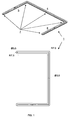
- Figure 1 is a view of the rear side of a peripheral skirt 1 that forms a U, or more generally a shape open on one side. It comprises a front branch 4, a right branch 5 and a left branch 6. In the present embodiment, the right branch 5 and the left branch 6 each make a right angle with the front branch 4.
- each branch There is a hole 7 at the end of each branch.
- the end of each side branch is rounded, with a 15 mm diameter circle.
- the square angle between side branches and front branch is similarly rounded.
- the center of the circle at the end of each side branch and at each square angle corresponds to the centre of the hole 7.
- the diameter of each hole 7 is 3.5 mm.
- Figure 2 is a front view and a view of each of the sides of the peripheral skirt 1.
- the peripheral skirt 1 comprises a molded part 2 and four strips 3. It comprises five holes 8 intended to receive fixation screws.
- the strips 3 are fixed on the molded part 2 between each pair of holes 8, for example using appropriate glue.
- Means other than screws for fixing the skirt to the device may also be envisaged by the Man Skilled in the Art: e.g. using glue, resilient plugs added to the skirt and destined to cooperate with appropriate holes of the device, etc...
- the front branch 4, the right branch 5 and the left branch 6 are 15 mm wide and 5 mm thick.
- the front branch length L1 is 340mm.
- Left and right branches' length L2 is 207 mm.
- Figure 3 is a view of the section BB of the peripheral skirt represented in figure 2.
- each branch is rounded with a lengthwise groove in the middle.
- the back side 11 of each branch is flat; when the peripheral skirt is fixed to a device, this allows the back side 11 of the peripheral skirt to be entirely in contact with the device.
- the section BB is designed as follows.
- B1 B2 O2 O1 It is comprised of a rectangle B1 B2 O2 O1.
- B1 B2 and O2 O1 are 7 mm.
- B1 O1 and O2 B2 are 4 mm.
- the section BB is also comprised of two quarter circles
- the section BB also comprises an open area that represents a rectangle CDEF, CD being 8 mm long and DE being 2 mm large.
- the middle of CD is also the middle of B1-B2.
- DE is the same direction as B1-O1.
- section BB comprises an open area that is 3.5mm large and crosses the middle of the section.
- Figure 4 is a view of the section DD of the peripheral skirt represented in figure 2. It comprises an open section that corresponds to the groove 30.
- the groove 9 is 1 mm deep and 5 mm wide.
- the groove 9 of the molded part 2 is intended to receive a strip 3.
- the strip 3 is glued on the molded part 2 between each screw hole 8 so that it does not cover the screw hole.
- the strip 3 is 5 mm wide and 2.36 to 3.18 mm thick.
- the screw head is low enough compared to the grove as to allow the strip to cover the screw head.
- the section BB is designed like the section DD with A1', B1', 01', A2', B2', 02' corresponding to A1, B1, 01, A2, B2, 02 indicated in figure 3.
- section BB The difference with the section BB is the absence of a hole 7 in that section, and the absence of the screw head cavity.
- the open area represented by the rectangle C'D'E'F' has different length than CDEF of figure 3.
- C'D' is 5 mm long and D'E' is 1 mm large. This corresponds to the groove.
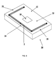
- Figures 5 represents a parallelepiped device 10 with a bottom panel 13 comprising a front edge 14, a left side edge 16, a right side edge 15 and a back edge 17.
- the device 10 is a set-top box television receiver and comprises a fan hole 18 on the bottom panel 13. It also comprises a peripheral skirt 1, such as previously described, and that is screwed to the bottom panel 13.
- the peripheral skirt 1 surrounds the fan hole 18.
- the front branch 4 of the peripheral skirt is fixed to the border front edge 14 of the bottom panel 13.
- the right 5 and left 6 side branches of the peripheral skirt are respectively fixed to the right 15 and left 16 side edges of the bottom panel 13.
- Air and noise are then routed to the open side, which is preferably oriented towards the back panel, away from the user when the device is placed in its working environment. Therefore, as the opening side is the back side 17, the peripheral skirt 1 contributes to the isolation of the front side 14 and the lateral sides 16 and 17 of the device 10 with regard to air flow and noise.
- the peripheral skirt is sensibly U shaped. However, it may also have a V shape, horseshoe shape, an arched shaped or a polygonal shape etc..., as long as its shape tends to direct air and/or noise from the ventilation opening into a predetermined direction. Moreover, the peripheral skirt tends to conform to the borders of the bottom panel of the device.
- the molded part is preferably manufactured using high impact polystyrene material, noted HIPS.
- HIPS high impact polystyrene material
- the density value of the HIPS is around 1040 kg/m3.
- the material is sufficiently rigid and absorbent to reduce vibrations of the device and shocks effects.
- the molded part material also ensures a minimum thickness between the bottom panel of the device and the place where it is put, even if a supplementary weight is added on the top of the device.
- the peripheral skirt is not flattened out under the weight of the device. This ensures then a minimum air flow rate for the device cooling.
- the strips 3 are manufactured using high density urethane plastic material.
- the density value is comprised between 240 and 480 kg/m3.
- the strip material enhances shock absorption and dampens vibrations.
- the described device is a set-top box. It could be any type of device that comprises a bottom panel and requires a peripheral skirt for enhanced stability. It could be any type of device that comprises a bottom panel with a ventilation hole.
Landscapes
- Engineering & Computer Science (AREA)
- Microelectronics & Electronic Packaging (AREA)
- Physics & Mathematics (AREA)
- Thermal Sciences (AREA)
- Cooling Or The Like Of Electrical Apparatus (AREA)
- Casings For Electric Apparatus (AREA)
Abstract
Description
- The present invention relates to a peripheral skirt intended to be attached underneath the bottom panel of a device, as well as a device comprising such a skirt.
- An electronic device, such as for example a set-top box, is a metal or plastic box intended to be placed on a surface such as a rack or a television receiver. The bottom of the metal box is usually not directly in contact with the supporting surface. A number of pads, typically made of a vibration-absorbing material such as rubber or felt, are attached to the bottom panel. This permits to isolate the device from the surface on which it is placed and to stabilize the device.
- Certain devices require internal fans in order to cool the numerous electronic components. The fans suck air from the box and expel it through a ventilation grate in order to create appropriate paths for the air flowing through the device. While the noise created by such fans may be acceptable in certain environments, it is less acceptable in a home cinema environment. Other components, such as a hard disk drive also generate noise which may be heard through the ventilation grate.
- The invention
EP1 052884A from Matsushita Electric Industrial Co, LTD, 15 November 2000, relates to a cooling structure of an electronic appliance, where the heat generated in an heat generating part is exhausted outside of the housing of the electronic appliance by the air passing through a wind tunnel. - It is therefore desirable to reduce the noise perceived by the users of the device.
- The present invention concerns an electronic device comprising a bottom panel, and a ventilation hole on the bottom panel, characterized in that it comprises a peripheral skirt attached to the bottom panel, the skirt surrounding the hole, and the skirt comprising an opening on one side of the bottom panel for permitting privileged evacuation of noise from the ventilation hole towards the opening.
- According to an embodiment of the invention, the bottom panel comprises a back side directed away from a user when the device is in functioning conditions, and that the opening is oriented towards the back side.
- According to an embodiment of the invention, the peripheral skirt tends to conform to the borders of the bottom panel.
- According to an embodiment of the invention, the skirt comprises a molded part and a strip, the molded part comprising a back side and a front side, the back side being fixed to the bottom panel of the device, the strip being fixed to the front side, the molded part being intended to ensure a minimum air flow rate for the device cooling, and the strip being intended to absorb vibrations from the device.
- According to an embodiment of the invention, a fan is placed against the ventilation hole within the device for creating an air flow through the opening.
- Another object of the invention is a peripheral skirt intended to be attached to a bottom panel of an electronic device comprising a ventilation hole on the bottom panel, characterized in that, when fixed to the device, the skirt surrounds the hole and comprises an opening to one side of the bottom panel for privileged evacuation of noise towards the opening.
- According to an embodiment of the invention, the peripheral skirt comprises a molded part intended to be fixed to the device and a strip fixed to the molded part, the molded part being intended to create a space of a minimum section when the device is placed on a surface, and the strip being intended to absorb vibrations.
- According to an embodiment of the invention, the molded part comprises a groove intended to allow the fastening of the strip.
- The invention will be better understood and illustrated by means of the following embodiment, in no way restrictive, and which will be described with reference to the appended figures among which:
- Figure 1 represents a rear view of the peripheral skirt according to one embodiment of the invention;
- Figure 2 represents a front view and a view of each side of the molded part of the peripheral skirt of figure 1;
- Figure 3 represents the section BB indicated in figure 2;
- Figure 4 represents the section DD indicated in figure 2;
- Figure 5 represents a device comprising a peripheral skirt.
- Figure 1 is a view of the rear side of a
peripheral skirt 1 that forms a U, or more generally a shape open on one side. It comprises afront branch 4, aright branch 5 and aleft branch 6. In the present embodiment, theright branch 5 and theleft branch 6 each make a right angle with thefront branch 4. - There is a
hole 7 at the end of each branch. The end of each side branch is rounded, with a 15 mm diameter circle. The square angle between side branches and front branch is similarly rounded. The center of the circle at the end of each side branch and at each square angle corresponds to the centre of thehole 7. The diameter of eachhole 7 is 3.5 mm. There is also ahole 7 in the middle of thefront branch 4. The holes are destined to facilitate fixing the skirt to electronic device with the help of screws. - Note that the dimensions are given as an example only: other dimensions may be used.
- Figure 2 is a front view and a view of each of the sides of the
peripheral skirt 1. Theperipheral skirt 1 comprises a moldedpart 2 and fourstrips 3. It comprises fiveholes 8 intended to receive fixation screws. Thestrips 3 are fixed on themolded part 2 between each pair ofholes 8, for example using appropriate glue. - Means other than screws for fixing the skirt to the device may also be envisaged by the Man Skilled in the Art: e.g. using glue, resilient plugs added to the skirt and destined to cooperate with appropriate holes of the device, etc...
- According to the present embodiment, the
front branch 4, theright branch 5 and theleft branch 6 are 15 mm wide and 5 mm thick. The front branch length L1 is 340mm. Left and right branches' length L2 is 207 mm. - Figure 3 is a view of the section BB of the peripheral skirt represented in figure 2.
- The front side 12 of each branch is rounded with a lengthwise groove in the middle. The
back side 11 of each branch is flat; when the peripheral skirt is fixed to a device, this allows theback side 11 of the peripheral skirt to be entirely in contact with the device. - It comprises an open section that corresponds to
hole 7 and the cavity intended to receive thescrew head 8. - The section BB is designed as follows.
- It is comprised of a rectangle B1 B2 O2 O1. B1 B2 and O2 O1 are 7 mm. B1 O1 and O2 B2 are 4 mm.
- The section BB is also comprised of two quarter circles
- A1O1B1 forms a right angle, and A1, B1 are in the perimeter of the quarter circle centered in O1.
- A2O2B2 forms a right angle, and A2, B2 are in the perimeter of a quarter circle centered in O2.
- The section BB also comprises an open area that represents a rectangle CDEF, CD being 8 mm long and DE being 2 mm large. The middle of CD is also the middle of B1-B2. DE is the same direction as B1-O1.
- Finally the section BB comprises an open area that is 3.5mm large and crosses the middle of the section.
- Figure 4 is a view of the section DD of the peripheral skirt represented in figure 2. It comprises an open section that corresponds to the groove 30.
- The
groove 9 is 1 mm deep and 5 mm wide. Thegroove 9 of the moldedpart 2 is intended to receive astrip 3. Thestrip 3 is glued on themolded part 2 between eachscrew hole 8 so that it does not cover the screw hole. Thestrip 3 is 5 mm wide and 2.36 to 3.18 mm thick. - In a variant embodiment, the screw head is low enough compared to the grove as to allow the strip to cover the screw head.
- The section BB is designed like the section DD with A1', B1', 01', A2', B2', 02' corresponding to A1, B1, 01, A2, B2, 02 indicated in figure 3.
- The difference with the section BB is the absence of a
hole 7 in that section, and the absence of the screw head cavity. The open area represented by the rectangle C'D'E'F' has different length than CDEF of figure 3. C'D' is 5 mm long and D'E' is 1 mm large. This corresponds to the groove. - Figures 5 represents a
parallelepiped device 10 with abottom panel 13 comprising afront edge 14, aleft side edge 16, aright side edge 15 and aback edge 17. - According to the present embodiment, the
device 10 is a set-top box television receiver and comprises afan hole 18 on thebottom panel 13. It also comprises aperipheral skirt 1, such as previously described, and that is screwed to thebottom panel 13. Theperipheral skirt 1 surrounds thefan hole 18. Thefront branch 4 of the peripheral skirt is fixed to theborder front edge 14 of thebottom panel 13. The right 5 and left 6 side branches of the peripheral skirt are respectively fixed to the right 15 and left 16 side edges of thebottom panel 13. - Air and noise are then routed to the open side, which is preferably oriented towards the back panel, away from the user when the device is placed in its working environment. Therefore, as the opening side is the
back side 17, theperipheral skirt 1 contributes to the isolation of thefront side 14 and the lateral sides 16 and 17 of thedevice 10 with regard to air flow and noise. - According to the present embodiment, the peripheral skirt is sensibly U shaped. However, it may also have a V shape, horseshoe shape, an arched shaped or a polygonal shape etc..., as long as its shape tends to direct air and/or noise from the ventilation opening into a predetermined direction. Moreover, the peripheral skirt tends to conform to the borders of the bottom panel of the device.
- According to the present embodiment, the molded part is preferably manufactured using high impact polystyrene material, noted HIPS. The density value of the HIPS is around 1040 kg/m3. The material is sufficiently rigid and absorbent to reduce vibrations of the device and shocks effects.
- The molded part material also ensures a minimum thickness between the bottom panel of the device and the place where it is put, even if a supplementary weight is added on the top of the device. The peripheral skirt is not flattened out under the weight of the device. This ensures then a minimum air flow rate for the device cooling.
- According to the present embodiment, the
strips 3 are manufactured using high density urethane plastic material. The density value is comprised between 240 and 480 kg/m3. The strip material enhances shock absorption and dampens vibrations. - The described device is a set-top box. It could be any type of device that comprises a bottom panel and requires a peripheral skirt for enhanced stability. It could be any type of device that comprises a bottom panel with a ventilation hole.
Claims (8)
- Electronic device (10) comprising a bottom panel (13), and a ventilation hole (19) on said bottom panel (13), characterized in that it comprises a peripheral skirt (1) attached to said bottom panel (13), said skirt (1) surrounding said hole (19), said skirt comprising an opening on one side of said bottom panel (13) for permitting privileged evacuation of noise from the ventilation hole towards said opening, said side being the side furthest away from the user when the device is in its working environment.
- Device (10) according to the preceding claim, characterized in that said bottom panel (13) comprises a back side (17) directed away from a user when said device is in functioning conditions, and that said opening is oriented towards said back side (17).
- Device (10) according to the preceding claims, characterized in that said peripheral skirt (1) tends to conform to the borders of said bottom panel (13).
- Device (10) according to the preceding claims, characterized in that said skirt (1) comprises a molded part (2) and a strip (3),- said molded part (2) comprising a back side (11) and a front side (12),- said back side (11) being fixed to the bottom panel of said device,- said strip (3) being fixed to said front side (12),- said molded part (2) being intended to ensure a minimum air flow rate for the device cooling, and- said strip (3) being intended to absorb vibrations from said device.
- Device (10) according to the preceding claims, characterized in that a fan is placed against said ventilation hole within the device for creating an air flow through the opening.
- Peripheral skirt (1) intended to be attached to a bottom panel (13) of an electronic device (10) comprising a ventilation hole (19) on said bottom panel (13), characterized in that when fixed to said device (10) said skirt (1) surrounds said hole and comprises an opening to one side of said bottom panel (13) for privileged evacuation of noise towards said opening, said side being the side furthest away from the user when the device is in its working environment.
- Peripheral skirt (1) according to claim 6, characterized in that it comprises a molded part (2) intended to be fixed to said device (1) and a strip (3) fixed to said molded part (2), said molded part (2) being intended to create a space of a minimum section when the device is placed on a surface, and said strip (3) being intended to absorb vibrations.
- Peripheral skirt (1) according to the preceding claim, characterized in that said molded part (2) comprises a groove (9) intended to allow the fastening of said strip (3).
Priority Applications (1)
| Application Number | Priority Date | Filing Date | Title |
|---|---|---|---|
| EP06118295A EP1758388B1 (en) | 2005-08-23 | 2006-08-02 | Peripheral skirt intended to be attached underneath the bottom panel of a device, and corresponding device |
Applications Claiming Priority (2)
| Application Number | Priority Date | Filing Date | Title |
|---|---|---|---|
| EP05107720A EP1758439A1 (en) | 2005-08-23 | 2005-08-23 | Peripheral skirt intended to be attached underneath the bottom panel of a device, and corresponding device |
| EP06118295A EP1758388B1 (en) | 2005-08-23 | 2006-08-02 | Peripheral skirt intended to be attached underneath the bottom panel of a device, and corresponding device |
Publications (2)
| Publication Number | Publication Date |
|---|---|
| EP1758388A1 true EP1758388A1 (en) | 2007-02-28 |
| EP1758388B1 EP1758388B1 (en) | 2010-07-07 |
Family
ID=35486584
Family Applications (2)
| Application Number | Title | Priority Date | Filing Date |
|---|---|---|---|
| EP05107720A Withdrawn EP1758439A1 (en) | 2005-08-23 | 2005-08-23 | Peripheral skirt intended to be attached underneath the bottom panel of a device, and corresponding device |
| EP06118295A Ceased EP1758388B1 (en) | 2005-08-23 | 2006-08-02 | Peripheral skirt intended to be attached underneath the bottom panel of a device, and corresponding device |
Family Applications Before (1)
| Application Number | Title | Priority Date | Filing Date |
|---|---|---|---|
| EP05107720A Withdrawn EP1758439A1 (en) | 2005-08-23 | 2005-08-23 | Peripheral skirt intended to be attached underneath the bottom panel of a device, and corresponding device |
Country Status (6)
| Country | Link |
|---|---|
| US (1) | US20070082599A1 (en) |
| EP (2) | EP1758439A1 (en) |
| JP (1) | JP5139653B2 (en) |
| KR (1) | KR101239302B1 (en) |
| CN (1) | CN1921747B (en) |
| DE (1) | DE602006015264D1 (en) |
Families Citing this family (3)
| Publication number | Priority date | Publication date | Assignee | Title |
|---|---|---|---|---|
| EP2019425A1 (en) | 2007-07-27 | 2009-01-28 | Semiconductor Energy Laboratory Co., Ltd. | Semiconductor device and method for manufacturing the same |
| JP2010212681A (en) * | 2009-03-09 | 2010-09-24 | Koshoku Kin | Carrier tape automatic feed apparatus for components mounting machine |
| CN102972103B (en) * | 2010-06-09 | 2016-08-03 | 汤姆森特许公司 | Set-top boxes with rubber feet |
Citations (3)
| Publication number | Priority date | Publication date | Assignee | Title |
|---|---|---|---|---|
| EP1052884A2 (en) | 1999-05-12 | 2000-11-15 | Matsushita Electric Industrial Co., Ltd. | Cooling structure of electronic appliance |
| WO2002071820A1 (en) * | 2001-03-05 | 2002-09-12 | Heeseob Park | Soundproofing cabinet with muffler for the noise reduction |
| EP1538629A1 (en) * | 2003-11-28 | 2005-06-08 | Thomson Licensing S.A. | Electronic apparatus with a data storage device |
Family Cites Families (23)
| Publication number | Priority date | Publication date | Assignee | Title |
|---|---|---|---|---|
| US2444887A (en) * | 1945-02-17 | 1948-07-06 | Ralph S Wyeth | Supplemental food-storage cabinet for use in conjunction with refrigerators |
| US3210456A (en) * | 1963-02-26 | 1965-10-05 | Mc Graw Edison Co | Ground level housing for electrical apparatus |
| GB1460759A (en) * | 1974-05-06 | 1977-01-06 | Quantel Ltd | Component cabinet for electronic circuitry |
| US4713099A (en) * | 1986-06-05 | 1987-12-15 | Schroeder Clifford A | Molded fiberglass air return filter grille |
| JPS635693U (en) * | 1986-06-27 | 1988-01-14 | ||
| US4753496A (en) * | 1987-08-31 | 1988-06-28 | Bussard Janice W | Cabinet with built-in fan |
| JPH0373483U (en) * | 1989-11-20 | 1991-07-24 | ||
| US5211460A (en) * | 1991-07-29 | 1993-05-18 | Liu Shih Ying | Shoe closets |
| US5428503A (en) * | 1992-03-24 | 1995-06-27 | Hitachi, Ltd. | Jet cooling apparatus for cooling electronic equipment and computer having the same mounted thereon |
| US5796580A (en) * | 1993-04-13 | 1998-08-18 | Hitachi, Ltd. | Air-cooled information processing apparatus having cooling air fan, sub-fan, and plural separated cooling air flow channels |
| JPH07202464A (en) * | 1993-12-28 | 1995-08-04 | Toshiba Corp | Electronic equipment device, cooling method for electronic equipment device, and fan device |
| US5467250A (en) * | 1994-03-21 | 1995-11-14 | Hubbell Incorporated | Electrical cabinet with door-mounted heat exchanger |
| US5608609A (en) * | 1995-09-11 | 1997-03-04 | Lucent Technologies Inc. | Outdoor cabinet for electronic equipment |
| CA2286331A1 (en) * | 1997-04-07 | 1998-10-15 | Calvin Blankenship | Warming system and method for heating various items utilized in surgical procedures |
| DE19810945C2 (en) * | 1998-03-13 | 2000-09-07 | Schroff Gmbh | Ventilable housing |
| US6127663A (en) * | 1998-10-09 | 2000-10-03 | Ericsson Inc. | Electronics cabinet cooling system |
| US6213866B1 (en) * | 1999-01-26 | 2001-04-10 | John S. Impellizzeri | Ventilating base |
| US6164369A (en) * | 1999-07-13 | 2000-12-26 | Lucent Technologies Inc. | Door mounted heat exchanger for outdoor equipment enclosure |
| FI108962B (en) * | 1999-08-20 | 2002-04-30 | Nokia Corp | Cooling system for plant cabinets |
| JP3073483U (en) * | 2000-05-24 | 2000-11-30 | 春夫 小嶋 | Ceramics with magnet |
| US6493224B1 (en) * | 2000-08-08 | 2002-12-10 | Lucent Technologies Inc. | Method and apparatus to increase convection heat transfer in an electrical system and a method of manufacturing the same |
| US6788535B2 (en) * | 2002-12-12 | 2004-09-07 | 3M Innovative Properties Company | Outdoor electronic equipment cabinet |
| US6847013B2 (en) * | 2003-02-10 | 2005-01-25 | Metal Masters Foodservice | Heated proofing cabinet |
-
2005
- 2005-08-23 EP EP05107720A patent/EP1758439A1/en not_active Withdrawn
-
2006
- 2006-08-02 DE DE602006015264T patent/DE602006015264D1/en active Active
- 2006-08-02 EP EP06118295A patent/EP1758388B1/en not_active Ceased
- 2006-08-09 US US11/501,592 patent/US20070082599A1/en not_active Abandoned
- 2006-08-21 JP JP2006223925A patent/JP5139653B2/en not_active Expired - Fee Related
- 2006-08-21 KR KR1020060078844A patent/KR101239302B1/en not_active Expired - Fee Related
- 2006-08-22 CN CN2006101213138A patent/CN1921747B/en not_active Expired - Fee Related
Patent Citations (3)
| Publication number | Priority date | Publication date | Assignee | Title |
|---|---|---|---|---|
| EP1052884A2 (en) | 1999-05-12 | 2000-11-15 | Matsushita Electric Industrial Co., Ltd. | Cooling structure of electronic appliance |
| WO2002071820A1 (en) * | 2001-03-05 | 2002-09-12 | Heeseob Park | Soundproofing cabinet with muffler for the noise reduction |
| EP1538629A1 (en) * | 2003-11-28 | 2005-06-08 | Thomson Licensing S.A. | Electronic apparatus with a data storage device |
Also Published As
| Publication number | Publication date |
|---|---|
| CN1921747A (en) | 2007-02-28 |
| EP1758439A1 (en) | 2007-02-28 |
| CN1921747B (en) | 2011-04-13 |
| JP5139653B2 (en) | 2013-02-06 |
| JP2007060660A (en) | 2007-03-08 |
| US20070082599A1 (en) | 2007-04-12 |
| KR20070023531A (en) | 2007-02-28 |
| KR101239302B1 (en) | 2013-03-05 |
| DE602006015264D1 (en) | 2010-08-19 |
| EP1758388B1 (en) | 2010-07-07 |
Similar Documents
| Publication | Publication Date | Title |
|---|---|---|
| US7002797B1 (en) | Noise-reducing blower structure | |
| US8089763B2 (en) | Heat-dissipating assembly for server | |
| JP5159933B1 (en) | TV, electronics | |
| EP1052884B1 (en) | Cooling structure of electronic appliance | |
| US6604799B2 (en) | Configurable air vents on a computer enclosure | |
| US20030128503A1 (en) | Display apparatus | |
| US20060002071A1 (en) | Electronic apparatus having a vibration absorber | |
| US7315445B2 (en) | Electrical apparatus | |
| EP1758388B1 (en) | Peripheral skirt intended to be attached underneath the bottom panel of a device, and corresponding device | |
| US20020054475A1 (en) | Hard disk drive mounting bracket for noise and vibration control | |
| US7965503B2 (en) | Fan and storage device mounting assembly for elecronic device | |
| KR101183240B1 (en) | Computer case | |
| CN2627262Y (en) | The shock-absorbing combination device of cooling fan and substrate | |
| KR20000004269A (en) | Apparatus for preventing a vibration of a television speaker | |
| JP2008525881A (en) | Casing and canopy | |
| JP2005100312A (en) | Electronics | |
| CN216735646U (en) | Novel electronic component storage box | |
| JP3104838U (en) | Computer case | |
| JP2005158946A (en) | Server rack | |
| CN216430004U (en) | Integrated fan module with shock absorption and noise reduction functions | |
| CN217739871U (en) | Silencing space key for computer keyboard and computer keyboard | |
| JPH0970088A (en) | Speaker device | |
| JP4873619B2 (en) | Rack structure | |
| JP2000065394A (en) | Air conditioner | |
| JP2013089897A (en) | Attachment structure of fan unit |
Legal Events
| Date | Code | Title | Description |
|---|---|---|---|
| PUAI | Public reference made under article 153(3) epc to a published international application that has entered the european phase |
Free format text: ORIGINAL CODE: 0009012 |
|
| AK | Designated contracting states |
Kind code of ref document: A1 Designated state(s): AT BE BG CH CY CZ DE DK EE ES FI FR GB GR HU IE IS IT LI LT LU LV MC NL PL PT RO SE SI SK TR |
|
| AX | Request for extension of the european patent |
Extension state: AL BA HR MK YU |
|
| 17P | Request for examination filed |
Effective date: 20070809 |
|
| AKX | Designation fees paid |
Designated state(s): DE FR GB |
|
| RAP1 | Party data changed (applicant data changed or rights of an application transferred) |
Owner name: THOMSON LICENSING |
|
| GRAP | Despatch of communication of intention to grant a patent |
Free format text: ORIGINAL CODE: EPIDOSNIGR1 |
|
| RAP1 | Party data changed (applicant data changed or rights of an application transferred) |
Owner name: THOMSON LICENSING |
|
| GRAS | Grant fee paid |
Free format text: ORIGINAL CODE: EPIDOSNIGR3 |
|
| GRAA | (expected) grant |
Free format text: ORIGINAL CODE: 0009210 |
|
| AK | Designated contracting states |
Kind code of ref document: B1 Designated state(s): DE FR GB |
|
| REG | Reference to a national code |
Ref country code: GB Ref legal event code: FG4D |
|
| REF | Corresponds to: |
Ref document number: 602006015264 Country of ref document: DE Date of ref document: 20100819 Kind code of ref document: P |
|
| PLBE | No opposition filed within time limit |
Free format text: ORIGINAL CODE: 0009261 |
|
| STAA | Information on the status of an ep patent application or granted ep patent |
Free format text: STATUS: NO OPPOSITION FILED WITHIN TIME LIMIT |
|
| 26N | No opposition filed |
Effective date: 20110408 |
|
| REG | Reference to a national code |
Ref country code: DE Ref legal event code: R097 Ref document number: 602006015264 Country of ref document: DE Effective date: 20110408 |
|
| REG | Reference to a national code |
Ref country code: FR Ref legal event code: PLFP Year of fee payment: 11 |
|
| PGFP | Annual fee paid to national office [announced via postgrant information from national office to epo] |
Ref country code: GB Payment date: 20160810 Year of fee payment: 11 |
|
| REG | Reference to a national code |
Ref country code: DE Ref legal event code: R082 Ref document number: 602006015264 Country of ref document: DE Representative=s name: DEHNS, DE Ref country code: DE Ref legal event code: R082 Ref document number: 602006015264 Country of ref document: DE Representative=s name: DEHNS PATENT AND TRADEMARK ATTORNEYS, DE Ref country code: DE Ref legal event code: R082 Ref document number: 602006015264 Country of ref document: DE Representative=s name: HOFSTETTER, SCHURACK & PARTNER PATENT- UND REC, DE |
|
| REG | Reference to a national code |
Ref country code: FR Ref legal event code: PLFP Year of fee payment: 12 |
|
| GBPC | Gb: european patent ceased through non-payment of renewal fee |
Effective date: 20170802 |
|
| PG25 | Lapsed in a contracting state [announced via postgrant information from national office to epo] |
Ref country code: GB Free format text: LAPSE BECAUSE OF NON-PAYMENT OF DUE FEES Effective date: 20170802 |
|
| REG | Reference to a national code |
Ref country code: FR Ref legal event code: PLFP Year of fee payment: 13 |
|
| REG | Reference to a national code |
Ref country code: DE Ref legal event code: R082 Ref document number: 602006015264 Country of ref document: DE Representative=s name: DEHNS, DE Ref country code: DE Ref legal event code: R081 Ref document number: 602006015264 Country of ref document: DE Owner name: INTERDIGITAL CE PATENT HOLDINGS SAS, FR Free format text: FORMER OWNER: THOMSON LICENSING, ISSY-LES-MOULINEAUX, FR Ref country code: DE Ref legal event code: R082 Ref document number: 602006015264 Country of ref document: DE Representative=s name: DEHNS PATENT AND TRADEMARK ATTORNEYS, DE |
|
| PGFP | Annual fee paid to national office [announced via postgrant information from national office to epo] |
Ref country code: DE Payment date: 20200827 Year of fee payment: 15 Ref country code: FR Payment date: 20200824 Year of fee payment: 15 |
|
| REG | Reference to a national code |
Ref country code: DE Ref legal event code: R119 Ref document number: 602006015264 Country of ref document: DE |
|
| PG25 | Lapsed in a contracting state [announced via postgrant information from national office to epo] |
Ref country code: FR Free format text: LAPSE BECAUSE OF NON-PAYMENT OF DUE FEES Effective date: 20210831 Ref country code: DE Free format text: LAPSE BECAUSE OF NON-PAYMENT OF DUE FEES Effective date: 20220301 |