EP1757951A1 - Thin metal layer vacuum vessels with composite structural support - Google Patents
Thin metal layer vacuum vessels with composite structural support Download PDFInfo
- Publication number
- EP1757951A1 EP1757951A1 EP06253557A EP06253557A EP1757951A1 EP 1757951 A1 EP1757951 A1 EP 1757951A1 EP 06253557 A EP06253557 A EP 06253557A EP 06253557 A EP06253557 A EP 06253557A EP 1757951 A1 EP1757951 A1 EP 1757951A1
- Authority
- EP
- European Patent Office
- Prior art keywords
- metallic
- composite
- sealed vessel
- containment piece
- piece
- Prior art date
- Legal status (The legal status is an assumption and is not a legal conclusion. Google has not performed a legal analysis and makes no representation as to the accuracy of the status listed.)
- Ceased
Links
- 239000002131 composite material Substances 0.000 title claims abstract description 80
- 229910052751 metal Inorganic materials 0.000 title description 7
- 239000002184 metal Substances 0.000 title description 7
- 238000000034 method Methods 0.000 claims description 15
- 239000000463 material Substances 0.000 claims description 11
- 239000011152 fibreglass Substances 0.000 claims description 6
- 238000004519 manufacturing process Methods 0.000 claims description 5
- 229910010293 ceramic material Inorganic materials 0.000 claims description 4
- 230000008878 coupling Effects 0.000 claims description 4
- 238000010168 coupling process Methods 0.000 claims description 4
- 238000005859 coupling reaction Methods 0.000 claims description 4
- 229920000049 Carbon (fiber) Polymers 0.000 claims 3
- 239000004917 carbon fiber Substances 0.000 claims 3
- VNWKTOKETHGBQD-UHFFFAOYSA-N methane Chemical compound C VNWKTOKETHGBQD-UHFFFAOYSA-N 0.000 claims 3
- 238000003384 imaging method Methods 0.000 description 8
- 238000002595 magnetic resonance imaging Methods 0.000 description 8
- 238000005481 NMR spectroscopy Methods 0.000 description 4
- 239000004033 plastic Substances 0.000 description 4
- 239000010935 stainless steel Substances 0.000 description 4
- 229910001220 stainless steel Inorganic materials 0.000 description 4
- 238000004611 spectroscopical analysis Methods 0.000 description 3
- 229910000975 Carbon steel Inorganic materials 0.000 description 2
- 239000004593 Epoxy Substances 0.000 description 2
- 229910052782 aluminium Inorganic materials 0.000 description 2
- XAGFODPZIPBFFR-UHFFFAOYSA-N aluminium Chemical compound [Al] XAGFODPZIPBFFR-UHFFFAOYSA-N 0.000 description 2
- 239000010962 carbon steel Substances 0.000 description 2
- 239000000919 ceramic Substances 0.000 description 2
- 238000001816 cooling Methods 0.000 description 2
- 238000004146 energy storage Methods 0.000 description 2
- 239000011888 foil Substances 0.000 description 2
- 238000004382 potting Methods 0.000 description 2
- RYGMFSIKBFXOCR-UHFFFAOYSA-N Copper Chemical compound [Cu] RYGMFSIKBFXOCR-UHFFFAOYSA-N 0.000 description 1
- 229910001275 Niobium-titanium Inorganic materials 0.000 description 1
- 238000007792 addition Methods 0.000 description 1
- WYTGDNHDOZPMIW-RCBQFDQVSA-N alstonine Natural products C1=CC2=C3C=CC=CC3=NC2=C2N1C[C@H]1[C@H](C)OC=C(C(=O)OC)[C@H]1C2 WYTGDNHDOZPMIW-RCBQFDQVSA-N 0.000 description 1
- 230000004888 barrier function Effects 0.000 description 1
- 239000004020 conductor Substances 0.000 description 1
- 229910052802 copper Inorganic materials 0.000 description 1
- 239000010949 copper Substances 0.000 description 1
- 238000002059 diagnostic imaging Methods 0.000 description 1
- 239000012777 electrically insulating material Substances 0.000 description 1
- 239000000835 fiber Substances 0.000 description 1
- 239000002657 fibrous material Substances 0.000 description 1
- 230000005669 field effect Effects 0.000 description 1
- 239000007789 gas Substances 0.000 description 1
- 239000001307 helium Substances 0.000 description 1
- 229910052734 helium Inorganic materials 0.000 description 1
- SWQJXJOGLNCZEY-UHFFFAOYSA-N helium atom Chemical compound [He] SWQJXJOGLNCZEY-UHFFFAOYSA-N 0.000 description 1
- 239000011810 insulating material Substances 0.000 description 1
- 239000007788 liquid Substances 0.000 description 1
- 150000002739 metals Chemical class 0.000 description 1
- 238000012986 modification Methods 0.000 description 1
- 230000004048 modification Effects 0.000 description 1
- RJSRQTFBFAJJIL-UHFFFAOYSA-N niobium titanium Chemical compound [Ti].[Nb] RJSRQTFBFAJJIL-UHFFFAOYSA-N 0.000 description 1
- 238000003466 welding Methods 0.000 description 1
Images



Classifications
-
- G—PHYSICS
- G01—MEASURING; TESTING
- G01R—MEASURING ELECTRIC VARIABLES; MEASURING MAGNETIC VARIABLES
- G01R33/00—Arrangements or instruments for measuring magnetic variables
- G01R33/20—Arrangements or instruments for measuring magnetic variables involving magnetic resonance
- G01R33/28—Details of apparatus provided for in groups G01R33/44 - G01R33/64
- G01R33/38—Systems for generation, homogenisation or stabilisation of the main or gradient magnetic field
- G01R33/381—Systems for generation, homogenisation or stabilisation of the main or gradient magnetic field using electromagnets
- G01R33/3815—Systems for generation, homogenisation or stabilisation of the main or gradient magnetic field using electromagnets with superconducting coils, e.g. power supply therefor
-
- Y—GENERAL TAGGING OF NEW TECHNOLOGICAL DEVELOPMENTS; GENERAL TAGGING OF CROSS-SECTIONAL TECHNOLOGIES SPANNING OVER SEVERAL SECTIONS OF THE IPC; TECHNICAL SUBJECTS COVERED BY FORMER USPC CROSS-REFERENCE ART COLLECTIONS [XRACs] AND DIGESTS
- Y10—TECHNICAL SUBJECTS COVERED BY FORMER USPC
- Y10T—TECHNICAL SUBJECTS COVERED BY FORMER US CLASSIFICATION
- Y10T428/00—Stock material or miscellaneous articles
- Y10T428/13—Hollow or container type article [e.g., tube, vase, etc.]
Definitions
- the invention relates generally to medical imaging systems, and more particularly to a composite structure for use in a magnetic resonance imaging system and a method of manufacturing the same.
- the vacuum vessel of an MRI magnet is generally made of components that are welded together during assembly of the magnet to form a pressure boundary. Therefore, the function of the vacuum vessel of an MRI magnet is to provide a reliable pressure boundary for maintaining proper vacuum operation. Any leakage or gas permeation over time will increase the vacuum pressure and, consequently, increase the heat load of the magnet.
- Vacuum vessels known in the art are usually made of metals such as stainless steel, carbon steel and aluminum. Although, metal vacuum vessels are strong enough to resist vacuum forces, they generate eddy currents and unwanted field distortions in the imaging volume when exposed to an AC field.
- non-metallic vacuum vessels tend to be permeable to gasses and moisture, which hampers the normal vacuum operation.
- a composite sealed vessel in accordance with one aspect of the present invention, includes a non-metallic, generally cylindrical inner containment piece, a non-metallic, generally cylindrical outer containment piece disposed around the inner containment piece.
- a pair of non-metallic flanges are disposed at ends of the inner and outer containment pieces to form a closed structure defining a cavity therein.
- the vessel also includes a metallic external lining disposed over the closed structure to form a leak-tight pressure boundary.
- a method for manufacturing the composite sealed vessel is also provided. Further, a system for reducing eddy current losses in a magnetic resonance (MR) system is also provided.
- MR magnetic resonance
- a composite sealed vessel in accordance with another aspect of the present invention, includes a non-metallic inner containment piece, and two non-metallic flanges coupled to the edges of the inner containment piece to form a composite structure having a cavity therein.
- An external lining is disposed over the composite structure to form a closed composite structure having a leak tight pressure boundary for maintaining a vacuum pressure within the cavity, wherein the external lining comprises thin metallic sheets welded over the inner containment piece and the two flanges, and a thick metallic sheet forming an outer containment piece.
- the magnet assembly 10 includes an outer shell (vessel) 12 surrounding a bore 14.
- the outer shell 12 includes an outer lining 16, an inner lining 18, and two annular end lining flanges 20 and 22.
- the outer lining 16, inner lining 18, and the two annular end lining flanges 20 and 22 together form a closed composite structure that encloses an evacuated volume as described below.
- the magnet assembly 10 includes the outer shell 12 surrounding the bore 14.
- the outer shell 12 is constructed to enclose a vacuum volume or a vacuum cavity 24.
- a superconducting magnet assembly 26 is disposed within the vacuum cavity 24.
- the outer shell 12 is constructed by disposing a composite outer cylinder 28 over a composite inner cylinder 30 in a concentric fashion.
- the composite outer cylinder 28 and the composite inner cylinder 30 are closed via two annular flanges 32 and 34, to form a closed composite structure.
- the composite outer cylinder 28, the composite inner cylinder 30, and the two flanges 32 and 34 may be made of a plastic or fiber material, such as but not limited to, a fiberglass material, a ceramic material, or a synthetic plastic material. Therefore, the two flanges 32 and 34 may be either thermally fused together or even separably joined with the composite outer cylinder 28 and the composite inner cylinder 30 at corners shown generally by reference numeral 36.
- the closed composite structure thus formed is then surrounded and sealed by thin metallic sheets that form an external lining over the closed composite structure.
- An outer metallic lining 16 is disposed proximate to the composite outer cylinder 28, while an inner metallic lining 18 is disposed proximate to the composite inner cylinder 30.
- Two annular end linings 20 and 22 are disposed proximate to the flanges 32 and 34, respectively.
- the outer metallic lining 16, the inner metallic lining 18, and the two annular end linings 20 and 22 may be made of metal, such as stainless steel, carbon steel, or aluminum. These components 16, 18, 20, and 22 may be welded together at the edges, as designated generally by reference numeral 38.
- the outer shell 12 is a sealed vacuum vessel enclosing the vacuum volume 24, which withstands vacuum forces shown generally by arrows 40.
- the magnetic field of MR magnet and gradient assembly 10, particularly important within bore 14, is less influenced to a large extent by metallic lining at the outer periphery 16. Therefore, the outer metallic lining 16 may be thicker than the inner metallic lining 18.
- the metallic lining at the outer periphery 16 is further away from the gradient coil and the imaging volume 14, and therefore is exposed to smaller gradient pulsing field, causing smaller field disturbance in the imaging volume 14.
- the thickness of the metallic lining depends upon the particular application, however, and is therefore a matter of design choice.
- the thickness of the metallic lining is determined by the eddy current skin-depth, which permits the lower frequency fields to penetrate through the sheet, while reflecting the higher frequency fields.
- the actual cut-off frequency is determined by the resistivity of the material and its thickness.
- the various metallic lining elements, for this MR magnet assembly 10 may be of a thickness of the order of a fraction of a millimeter of stainless steel for the inner metallic lining 18, and 1 to 2 millimeter of stainless steel for the outer metallic lining 16. This thickness allows lower frequency fields, of less than about 100 Hz, to pass through.
- the design frequency cut-off depends on the particular application.
- this frequency may be about 100 Hz to about 500 Hz; for a power superconducting magnetic energy storage application, from about 500 Hz to about 5 kHz; and, for a nuclear magnetic resonance spectroscopy (NMR) system, the range may be between about 2 kHz and about 10 kHz.
- the superconducting magnet assembly 26 is disposed within the outer shell 12 in the vacuum volume 24 via mechanically support structures that are not shown for clarity.
- the superconducting magnet assembly 26 includes a composite bobbin-shaped structure 42, which includes a plurality of recesses 44.
- the composite bobbin 42 may be made of thermally conductive strands, such as copper, that may be co-wound, intertwined, with fiberglass strands and reinforced with, but not limited to, epoxy to form a composite body.
- a superconducting coil 46 which may be made of a coil of metallic or ceramic wires, such as of Niobium-Titanium wires.
- the superconducting coil 46 wound in each recess 44 may be interlinked with that disposed in another proximate recess 44, via electrical couplers or jumpers.
- a cryogenic coil 48 is wound or disposed over the composite bobbin 42, such that the cryogenic coil 48 is proximate to the composite bobbin 42 in locations not including the recesses 44.
- the superconducting coil 46 is wound in the recesses 44 of the composite bobbin 42.
- Each segment of the superconducting coil 46 disposed in each recess 44 may be disposed over an insulating liner 50 that prevents the superconducting coil 46 to be electrically coupled to the composite bobbin 42.
- the insulating liner 50 may be an epoxy liner, or other electrically insulating material.
- the wires of the superconducting coil 46 may also be coated with an insulating material. The structure thus formed is coated with a potting material 52 that forms a uniform overlayer.
- Leads of the superconducting coil 46, shown generally by reference numeral 54, and conduits of the cryogenic coil 48, shown generally by reference numeral 56, may be conducted out of the potting 52 for electrical coupling with magnet operation control circuitry and cryogen feed mechanism (not shown), respectively.
- the outer shell 12 includes a composite outer cylinder 28 and a composite inner cylinder 30 that are arranged concentric to each other with respect to their central axes.
- Two annular flanges 32 and 34 are arranged axially to the composite cylinders 28 and 30, such that the annular flanges 32 and 34 and the composite cylinders 28 and 30 together form the closed composite structure enveloping an annular inner volume.
- the diameter of the composite outer cylinder 28, and the outer diameters of the annular flanges 32 and 34 are the same.
- the diameter of the composite inner cylinder 30, and the inner diameters of the annular flanges 32 and 34 are the same.
- a thin outer metallic lining 16 having diameter substantially equal to the outer diameter of the composite outer cylinder 28 is arranged radially over the composite outer cylinder 28.
- Another thin inner metallic lining 18 having diameter substantially equal to the inner diameter of the composite inner cylinder 30 is also arranged radially within the composite inner cylinder 30.
- These metallic linings 16 and 18 are then welded together with two annular end linings 20 and 22, which are also arranged axially to the metallic linings 16 and 18.
- the outer metallic lining 16 may be thicker than the inner metallic lining 18.
- welding of these metallic sheets 16, 18, 20, and 22 ensures the outer shell thus formed to be vacuum-sealed.
- the underlying composite material provides the necessary strength.
- the lining provides an airtight boundary to prevent leakage into the vessel through the composite material.
- FIG. 4 is a cross-sectional view of an alternative embodiment of an outer shell 58 for use in the magnet assembly of FIG. 1.
- the outer shell 58 includes a composite inner cylinder 30, and an outer metallic cylinder 60.
- the composite inner cylinder 30 and the outer metallic cylinder 60 are joined using annular flanges 32 and 34.
- An inner lining 18, two annular metallic linings 20 and 22 are then welded together at the joints or corners 38.
- the outer shell thus formed includes a bore 14, as shown.
- the outer cylinder 60 is made of a metal, the metal cylinder is less influenced by AC fields superimposed on the strong magnetic field generated by the superconducting magnet assembly 26 that is disposed within the vacuum cavity 24. This is because the magnetic field is directed towards the centre into the bore.
- the outer cylinder 60 is thus relatively spaced from the more important portion of the field.
- FIG. 5 an exploded view of an alternative embodiment of an outer shell 62 for use in a magnet assembly is shown.
- the outer shell 62 is constructed using a composite cylinder 64, which is joined together via two flanges, an upper composite flange 66, and a lower composite flange 68.
- the composite cylinder 64 and the composite flanges 66 and 68 may be made of a fiber or plastic material, such as fiberglass, ceramic, or plastic. These components 64, 66, and 68 may be thermally fused or joined to form a closed pancake-shaped structure.
- a thin metallic outer lining 70 having an inner diameter substantially equal to the outer diameter of the composite cylinder 64 is then welded with two metallic discs, an upper metallic lining 72 and a lower metallic lining 74.
- the outer shell 62 thus formed includes a vacuum volume or a vacuum cavity, within which is disposed a superconducting magnet assembly.
- Such a magnet assembly may be utilized for an open MR system, such as an open MRI or open magnetic resonance
- FIG. 6 is a diagrammatic view of a superconducting magnet that may be disposed horizontally within an outer shell of a magnet assembly in an MR system.
- the composite bobbin 42 of the superconducting magnet assembly 26 includes recesses 44. Although only two recesses 44 are shown, the composite bobbin 42 may include more recesses.
- the recesses 44 are wound with a superconducting coil 46.
- the superconducting coil 46 in the two recesses 44 are joined together via jumpers or electrical coupling that runs over the composite bobbin 42. Leads 54 of the superconducting coil 46 are conducted to electrical coupling with a magnet operation control circuitry.
- a cryogen coil 76 is arranged over the composite bobbin 42 in an anti-vapor-locking configuration, as shown.
- the cryogen coil 76 may be disposed in a commonly known refrigerator cooling coil configuration.
- This refrigerator cooling coil configuration in the horizontally-oriented superconducting magnet structure 26 prevents vapor-locking of the cryogen, as will be appreciated by those skilled in the art.
- the cryogen feed mechanism feeds liquid helium, or other cryogen known in the art, into the cryogen coil 76 in a direction shown generally by reference numeral 78.
- the cryogen flows down into the bottom 80 of the cryogen coil 76.
- the cryogen vaporizes and passes through the serpentine cryogen coil 76, without any cryogen vapor being locked in the cryogen coil 76.
- the vaporized cryogen escapes into the cryogen feed mechanism in the direction generally shown by reference numeral 82.
- the composite bobbin 42 made of thermally conductive material, as described previously helps in conducting heat away from the superconducting coils thus maintaining superconducting operation. The generated heat is conducted away towards the cryogenic coil 48. The thermally conductive composite bobbin 42 therefore reduces the thermal gradient between the superconducting coil 46 and the cryogenic coil 48.
- FIG. 7 is a diagrammatic view of a superconducting magnet that may be disposed vertically within an outer shell of a magnet assembly in an MR system.
- FIG. 7 shows the composite bobbin 42 of the superconducting magnet assembly 26 including the recesses 44.
- cryogen coil 84 is arranged over the composite bobbin 42 in an anti-vapor-locking configuration.
- the cryogen coil 84 is disposed in a helical configuration. Again, this helical configuration in the vertically-oriented superconducting magnet structure 26 prevents vapor-locking of the cryogen.
- the cryogen feed mechanism feeds cryogen into the cryogen coil 84 in a direction shown generally by reference numeral 86.
- the cryogen cools the superconducting magnet 26 and vaporizes through the spiral cryogen coil 84.
- the vaporized cryogen escapes into the cryogen feed mechanism in the direction generally shown by reference numeral 88.
- a magnetic resonance (MR) system 90 such as for a magnetic resonance imaging or magnetic resonance spectroscopy application, is shown in which the forgoing structures are incorporated.
- the MR system 90 shows a closed MR system, having a bore 92 for receiving a subject 94.
- Subject 94 may lie over a patient table 96 that may be introduced into the bore 92.
- a magnet assembly 10 including a superconducting magnet assembly 26 made via the techniques discussed above may be utilized to generate the magnetic field for the MR system 90.
- the superconducting operation may be controlled via an imaging control circuitry 98.
- the magnetic field for the open MR system 100 may be generated by a magnet assembly 10.
- the magnet assembly 10 may include an outer shell 62, constructed in accordance with the teachings of FIG. 5.
- a superconducting magnet assembly 26 may be disposed, which may have a thick disc shape without a bore. Again, the superconducting operation may be controlled via an imaging control circuitry 98.
- the magnet assembly 10 including the outer shell 12 that encloses the superconducting magnet assembly 26, may be constructed in a conventional patient bore configuration, an open MRI configuration, a long-U configuration, among others.
Landscapes
- Physics & Mathematics (AREA)
- Electromagnetism (AREA)
- Condensed Matter Physics & Semiconductors (AREA)
- General Physics & Mathematics (AREA)
- Magnetic Resonance Imaging Apparatus (AREA)
- Containers, Films, And Cooling For Superconductive Devices (AREA)
Abstract
Description
- The invention relates generally to medical imaging systems, and more particularly to a composite structure for use in a magnetic resonance imaging system and a method of manufacturing the same.
- The vacuum vessel of an MRI magnet is generally made of components that are welded together during assembly of the magnet to form a pressure boundary. Therefore, the function of the vacuum vessel of an MRI magnet is to provide a reliable pressure boundary for maintaining proper vacuum operation. Any leakage or gas permeation over time will increase the vacuum pressure and, consequently, increase the heat load of the magnet.
- Vacuum vessels known in the art are usually made of metals such as stainless steel, carbon steel and aluminum. Although, metal vacuum vessels are strong enough to resist vacuum forces, they generate eddy currents and unwanted field distortions in the imaging volume when exposed to an AC field.
- Attempts have been made to construct non-metallic vacuum vessels. However, non-metallic vacuum vessels tend to be permeable to gasses and moisture, which hampers the normal vacuum operation.
- Similarly, attempts have been made to use thin metallic foils over the non-metallic vacuum composite structures for providing vapor barrier. One major disadvantage with such composite structures is that the metallic foils may not seal properly at the flange joints of the vacuum composite structures.
- Thus, there is a need for an impermeable vacuum composite structure that provides reduced field effects from eddy currents.
- In accordance with one aspect of the present invention, a composite sealed vessel is provided. The vessel includes a non-metallic, generally cylindrical inner containment piece, a non-metallic, generally cylindrical outer containment piece disposed around the inner containment piece. A pair of non-metallic flanges are disposed at ends of the inner and outer containment pieces to form a closed structure defining a cavity therein. The vessel also includes a metallic external lining disposed over the closed structure to form a leak-tight pressure boundary. A method for manufacturing the composite sealed vessel is also provided. Further, a system for reducing eddy current losses in a magnetic resonance (MR) system is also provided.
- In accordance with another aspect of the present invention, a composite sealed vessel is provided. The composite sealed vessel includes a non-metallic inner containment piece, and two non-metallic flanges coupled to the edges of the inner containment piece to form a composite structure having a cavity therein. An external lining is disposed over the composite structure to form a closed composite structure having a leak tight pressure boundary for maintaining a vacuum pressure within the cavity, wherein the external lining comprises thin metallic sheets welded over the inner containment piece and the two flanges, and a thick metallic sheet forming an outer containment piece.
- The invention will now be described in greater detail, by way of example, with reference to the drawings, in which:-
- FIG. 1 is a perspective view of a magnet assembly in accordance with aspects of the present technique;
- FIG. 2 is a cross-sectional view of the magnet assembly of FIG. 1 taken along line II-II of FIG. 1;
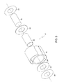
- FIG. 3 is an exploded view of an outer shell (vessel) of the magnet assembly of FIG. 1 in accordance with aspects of the present technique;
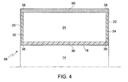
- FIG. 4 is a cross-sectional view of an alternative embodiment of the outer shell (vessel) taken along line II-II of FIG. 1 in accordance with aspects of the present technique;
- FIG. 5 is an exploded view of an alternative embodiment of an outer shell for use in a magnet assembly in accordance with aspects of the present technique;
- FIG. 6 is a diagrammatic view of a horizontally-oriented superconducting magnet in accordance with aspects of the present technique;
- FIG. 7 is a diagrammatic view of a vertically-oriented superconducting magnet in accordance with aspects of the present technique;
- FIG. 8 is a diagrammatic representation of a closed MR system illustrating a superconducting magnet assembly disposed within the MR system in accordance with aspects of the present technique; and
- FIG. 9 is a diagrammatic representation of an open MR system illustrating a superconducting magnet assembly disposed within the MR system in accordance with aspects of the present technique.
- In the subsequent paragraphs, an approach for manufacturing a superconducting magnet assembly will be explained in detail. The approach described hereinafter produces a superconducting magnet structure with reduced eddy current and eddy current induced magnetic field, such as for motors, generators, power superconducting magnetic energy storage applications, and magnetic resonance (MR) applications, including nuclear magnetic resonance spectroscopy (NMR) applications, magnetic resonance imaging (MRI) or magnetic resonance spectroscopy. The various aspects of the present technique will be explained, by way of example for an exemplary MR application, with the aid of figures hereinafter. Although the present techniques will be explained with reference to an MR application, it should be appreciated that the teachings of the present techniques may be applied to other applications where AC losses need to be contained for efficient operation.
- Referring generally to FIG. 1, manufacturing techniques will be described by reference to a magnet assembly designated generally by
numeral 10. Themagnet assembly 10 includes an outer shell (vessel) 12 surrounding abore 14. As will be appreciated by those skilled in the art, in an imaging application, a subject is placed in thebore 14 for imaging. Thus, thebore 14 provides access to the imaging volume for a subject. Theouter shell 12 includes anouter lining 16, aninner lining 18, and two annularend lining flanges outer lining 16,inner lining 18, and the two annularend lining flanges - Referring now to FIG. 2, a cross-sectional view of the
magnet assembly 10 of FIG. 1 taken along line II-II of FIG. 1, is illustrated. As illustrated, themagnet assembly 10 includes theouter shell 12 surrounding thebore 14. Theouter shell 12 is constructed to enclose a vacuum volume or avacuum cavity 24. Within thevacuum cavity 24, asuperconducting magnet assembly 26 is disposed. Theouter shell 12 is constructed by disposing a compositeouter cylinder 28 over a compositeinner cylinder 30 in a concentric fashion. The compositeouter cylinder 28 and the compositeinner cylinder 30 are closed via twoannular flanges outer cylinder 28, the compositeinner cylinder 30, and the twoflanges flanges outer cylinder 28 and the compositeinner cylinder 30 at corners shown generally byreference numeral 36. - The closed composite structure thus formed is then surrounded and sealed by thin metallic sheets that form an external lining over the closed composite structure. An outer
metallic lining 16 is disposed proximate to the compositeouter cylinder 28, while an innermetallic lining 18 is disposed proximate to the compositeinner cylinder 30. Twoannular end linings flanges metallic lining 16, the innermetallic lining 18, and the twoannular end linings components reference numeral 38. Thus, theouter shell 12 is a sealed vacuum vessel enclosing thevacuum volume 24, which withstands vacuum forces shown generally byarrows 40. - It may be noted that the magnetic field of MR magnet and
gradient assembly 10, particularly important withinbore 14, is less influenced to a large extent by metallic lining at theouter periphery 16. Therefore, the outermetallic lining 16 may be thicker than the innermetallic lining 18. The metallic lining at theouter periphery 16 is further away from the gradient coil and theimaging volume 14, and therefore is exposed to smaller gradient pulsing field, causing smaller field disturbance in theimaging volume 14. The thickness of the metallic lining depends upon the particular application, however, and is therefore a matter of design choice. The thickness of the metallic lining is determined by the eddy current skin-depth, which permits the lower frequency fields to penetrate through the sheet, while reflecting the higher frequency fields. The actual cut-off frequency is determined by the resistivity of the material and its thickness. For example, the various metallic lining elements, for thisMR magnet assembly 10, may be of a thickness of the order of a fraction of a millimeter of stainless steel for the innermetallic lining 18, and 1 to 2 millimeter of stainless steel for the outermetallic lining 16. This thickness allows lower frequency fields, of less than about 100 Hz, to pass through. - Similarly, in various other applications, the design frequency cut-off depends on the particular application. For example, in a motor or generator this frequency may be about 100 Hz to about 500 Hz; for a power superconducting magnetic energy storage application, from about 500 Hz to about 5 kHz; and, for a nuclear magnetic resonance spectroscopy (NMR) system, the range may be between about 2 kHz and about 10 kHz.
- The
superconducting magnet assembly 26 is disposed within theouter shell 12 in thevacuum volume 24 via mechanically support structures that are not shown for clarity. Thesuperconducting magnet assembly 26 includes a composite bobbin-shapedstructure 42, which includes a plurality ofrecesses 44. Thecomposite bobbin 42 may be made of thermally conductive strands, such as copper, that may be co-wound, intertwined, with fiberglass strands and reinforced with, but not limited to, epoxy to form a composite body. - In each of the
recesses 44, is disposed asuperconducting coil 46, which may be made of a coil of metallic or ceramic wires, such as of Niobium-Titanium wires. Thesuperconducting coil 46 wound in eachrecess 44 may be interlinked with that disposed in anotherproximate recess 44, via electrical couplers or jumpers. Acryogenic coil 48 is wound or disposed over thecomposite bobbin 42, such that thecryogenic coil 48 is proximate to thecomposite bobbin 42 in locations not including therecesses 44. - As previously described, the
superconducting coil 46 is wound in therecesses 44 of thecomposite bobbin 42. Each segment of thesuperconducting coil 46 disposed in eachrecess 44 may be disposed over an insulatingliner 50 that prevents thesuperconducting coil 46 to be electrically coupled to thecomposite bobbin 42. The insulatingliner 50 may be an epoxy liner, or other electrically insulating material. It may be noted that the wires of thesuperconducting coil 46 may also be coated with an insulating material. The structure thus formed is coated with apotting material 52 that forms a uniform overlayer. Leads of thesuperconducting coil 46, shown generally byreference numeral 54, and conduits of thecryogenic coil 48, shown generally byreference numeral 56, may be conducted out of the potting 52 for electrical coupling with magnet operation control circuitry and cryogen feed mechanism (not shown), respectively. - Turning now to FIG. 3, an exploded view of an
outer shell 12 of themagnet assembly 10 of FIG. 1 is shown. As illustrated, theouter shell 12 includes a compositeouter cylinder 28 and a compositeinner cylinder 30 that are arranged concentric to each other with respect to their central axes. Twoannular flanges composite cylinders annular flanges composite cylinders outer cylinder 28, and the outer diameters of theannular flanges inner cylinder 30, and the inner diameters of theannular flanges - A thin outer
metallic lining 16 having diameter substantially equal to the outer diameter of the compositeouter cylinder 28 is arranged radially over the compositeouter cylinder 28. Another thin innermetallic lining 18 having diameter substantially equal to the inner diameter of the compositeinner cylinder 30 is also arranged radially within the compositeinner cylinder 30. Thesemetallic linings annular end linings metallic linings metallic lining 16 may be thicker than the innermetallic lining 18. Moreover, welding of thesemetallic sheets - FIG. 4 is a cross-sectional view of an alternative embodiment of an
outer shell 58 for use in the magnet assembly of FIG. 1. As illustrated, theouter shell 58 includes a compositeinner cylinder 30, and an outermetallic cylinder 60. The compositeinner cylinder 30 and the outermetallic cylinder 60 are joined usingannular flanges inner lining 18, two annularmetallic linings corners 38. The outer shell thus formed includes abore 14, as shown. Although, theouter cylinder 60 is made of a metal, the metal cylinder is less influenced by AC fields superimposed on the strong magnetic field generated by thesuperconducting magnet assembly 26 that is disposed within thevacuum cavity 24. This is because the magnetic field is directed towards the centre into the bore. Theouter cylinder 60 is thus relatively spaced from the more important portion of the field. - Referring generally to FIG. 5, an exploded view of an alternative embodiment of an
outer shell 62 for use in a magnet assembly is shown. Theouter shell 62 is constructed using acomposite cylinder 64, which is joined together via two flanges, an uppercomposite flange 66, and a lowercomposite flange 68. Thecomposite cylinder 64 and thecomposite flanges components outer lining 70 having an inner diameter substantially equal to the outer diameter of thecomposite cylinder 64 is then welded with two metallic discs, an uppermetallic lining 72 and a lowermetallic lining 74. Theouter shell 62 thus formed includes a vacuum volume or a vacuum cavity, within which is disposed a superconducting magnet assembly. Such a magnet assembly may be utilized for an open MR system, such as an open MRI or open magnetic resonance spectroscopy systems. - FIG. 6 is a diagrammatic view of a superconducting magnet that may be disposed horizontally within an outer shell of a magnet assembly in an MR system. As shown, the
composite bobbin 42 of thesuperconducting magnet assembly 26 includesrecesses 44. Although only tworecesses 44 are shown, thecomposite bobbin 42 may include more recesses. Therecesses 44 are wound with asuperconducting coil 46. Thesuperconducting coil 46 in the tworecesses 44 are joined together via jumpers or electrical coupling that runs over thecomposite bobbin 42. Leads 54 of thesuperconducting coil 46 are conducted to electrical coupling with a magnet operation control circuitry. Acryogen coil 76 is arranged over thecomposite bobbin 42 in an anti-vapor-locking configuration, as shown. For example, in a horizontally-orientedsuperconducting magnet structure 26, thecryogen coil 76 may be disposed in a commonly known refrigerator cooling coil configuration. This refrigerator cooling coil configuration in the horizontally-orientedsuperconducting magnet structure 26 prevents vapor-locking of the cryogen, as will be appreciated by those skilled in the art. The cryogen feed mechanism feeds liquid helium, or other cryogen known in the art, into thecryogen coil 76 in a direction shown generally byreference numeral 78. The cryogen flows down into the bottom 80 of thecryogen coil 76. As the cryogen cools thesuperconducting magnet 26, the cryogen vaporizes and passes through theserpentine cryogen coil 76, without any cryogen vapor being locked in thecryogen coil 76. The vaporized cryogen escapes into the cryogen feed mechanism in the direction generally shown byreference numeral 82. - The
composite bobbin 42, made of thermally conductive material, as described previously helps in conducting heat away from the superconducting coils thus maintaining superconducting operation. The generated heat is conducted away towards thecryogenic coil 48. The thermally conductivecomposite bobbin 42 therefore reduces the thermal gradient between thesuperconducting coil 46 and thecryogenic coil 48. - FIG. 7 is a diagrammatic view of a superconducting magnet that may be disposed vertically within an outer shell of a magnet assembly in an MR system. FIG. 7 shows the
composite bobbin 42 of thesuperconducting magnet assembly 26 including therecesses 44. As shown,cryogen coil 84 is arranged over thecomposite bobbin 42 in an anti-vapor-locking configuration. In this vertically-orientedsuperconducting magnet structure 26, thecryogen coil 84 is disposed in a helical configuration. Again, this helical configuration in the vertically-orientedsuperconducting magnet structure 26 prevents vapor-locking of the cryogen. The cryogen feed mechanism feeds cryogen into thecryogen coil 84 in a direction shown generally byreference numeral 86. The cryogen cools thesuperconducting magnet 26 and vaporizes through thespiral cryogen coil 84. The vaporized cryogen escapes into the cryogen feed mechanism in the direction generally shown byreference numeral 88. - The forgoing structures may be used in a range of systems and applications, such as for magnetic resonance imaging. Referring generally to FIG. 8, a magnetic resonance (MR)
system 90, such as for a magnetic resonance imaging or magnetic resonance spectroscopy application, is shown in which the forgoing structures are incorporated. TheMR system 90 shows a closed MR system, having abore 92 for receiving a subject 94.Subject 94 may lie over a patient table 96 that may be introduced into thebore 92. Amagnet assembly 10 including asuperconducting magnet assembly 26 made via the techniques discussed above may be utilized to generate the magnetic field for theMR system 90. The superconducting operation may be controlled via animaging control circuitry 98. - Referring now to FIG. 9, an
open MR system 100 is shown. The magnetic field for theopen MR system 100 may be generated by amagnet assembly 10. Themagnet assembly 10 may include anouter shell 62, constructed in accordance with the teachings of FIG. 5. Within theouter shell 62, asuperconducting magnet assembly 26 may be disposed, which may have a thick disc shape without a bore. Again, the superconducting operation may be controlled via animaging control circuitry 98. - It will be appreciated that various additions to or modifications of the above described embodiments may be made without departing from the scope of the invention. For example, the
magnet assembly 10 including theouter shell 12 that encloses thesuperconducting magnet assembly 26, may be constructed in a conventional patient bore configuration, an open MRI configuration, a long-U configuration, among others.
Claims (10)
- A composite sealed vessel (12), comprising:a non-metallic, generally cylindrical inner containment piece (30);a non-metallic, generally cylindrical outer containment piece (28) disposed around the inner containment piece (30);a pair of non-metallic flanges (32, 34) disposed at ends of the inner and outer containment pieces (28, 30) to form a closed structure defining a cavity (24) therein; anda metallic external lining (16, 18) disposed over the closed structure to form a leak-tight pressure boundary.
- The composite sealed vessel (12) of claim 1, wherein the inner containment piece (30) comprises one of a fiberglass material, carbon fiber material, or a ceramic material.
- The composite sealed vessel (12) of claim 1, wherein the outer containment piece (28) comprises one of a fiberglass material, carbon fiber material, or a ceramic material.
- The composite sealed vessel (12) of claim 1, wherein the pair of flanges (32, 34) comprises one of a fiberglass material, carbon fiber material, or a ceramic material.
- The composite sealed vessel (12) of claim 1, wherein the metallic external lining (16, 18) comprises thin high-resistivity metallic sheets (16, 18, 20, 22) welded together over exterior surfaces of the closed structure.
- The composite sealed vessel (12) of claim 1, wherein the metallic external lining (16, 18) comprises a thick high-resistivity metallic sheet (16) proximate to the outer containment piece (28) of the closed structure.
- The composite sealed vessel (12) of claim 1, wherein the metallic external lining (16, 18) allows low frequencies to penetrate through and shields high frequencies.
- The composite sealed vessel (12) of claim 1, comprising a superconducting magnet (26) disposed in the cavity (24).
- A method for manufacturing a composite sealed vessel (12), comprising:disposing a non-metallic inner containment piece (30) and a non-metallic outer containment piece (28) in a concentric configuration;forming a closed composite structure by coupling the non-metallic inner containment piece (30) and the non-metallic outer containment piece (28) via two non-metallic flanges (32, 34); andlayering the closed composite structure with a sealed thin metallic external lining (16, 18) for forming a leak-tight pressure boundary around the closed composite structure.
- A composite sealed vessel (12), comprising:a non-metallic inner containment piece (30);two non-metallic flanges (32, 34) coupled to the edges of the inner containment piece (30) to form a composite structure having a cavity (24) therein; andan external lining disposed over the composite structure to form a closed composite structure having a leak tight pressure boundary for maintaining a vacuum pressure within the cavity (24), wherein the external lining comprises thin metallic sheets (18, 20, 22) welded over the inner containment piece (30) and the two flanges (32, 34), and a thick metallic sheet forming an outer containment piece (60).
Applications Claiming Priority (1)
| Application Number | Priority Date | Filing Date | Title |
|---|---|---|---|
| US11/183,274 US7705701B2 (en) | 2005-07-15 | 2005-07-15 | Thin metal layer vacuum vessels with composite structural support |
Publications (1)
| Publication Number | Publication Date |
|---|---|
| EP1757951A1 true EP1757951A1 (en) | 2007-02-28 |
Family
ID=37626464
Family Applications (1)
| Application Number | Title | Priority Date | Filing Date |
|---|---|---|---|
| EP06253557A Ceased EP1757951A1 (en) | 2005-07-15 | 2006-07-06 | Thin metal layer vacuum vessels with composite structural support |
Country Status (3)
| Country | Link |
|---|---|
| US (1) | US7705701B2 (en) |
| EP (1) | EP1757951A1 (en) |
| JP (1) | JP5432429B2 (en) |
Cited By (1)
| Publication number | Priority date | Publication date | Assignee | Title |
|---|---|---|---|---|
| WO2009077780A1 (en) * | 2007-12-18 | 2009-06-25 | Siemens Plc | An outer vacuum chamber for a cryogenically cooled mri magnet |
Families Citing this family (20)
| Publication number | Priority date | Publication date | Assignee | Title |
|---|---|---|---|---|
| US9005138B2 (en) * | 2005-08-25 | 2015-04-14 | Cook Medical Technologies Llc | Wire guide having distal coupling tip |
| US7731693B2 (en) * | 2005-10-27 | 2010-06-08 | Cook Incorporated | Coupling wire guide |
| US8137291B2 (en) * | 2005-10-27 | 2012-03-20 | Cook Medical Technologies Llc | Wire guide having distal coupling tip |
| DE102006000923B4 (en) * | 2006-01-05 | 2009-10-29 | Siemens Ag | Magnetic resonance device, comprising a, preferably substantially cylindrical vacuum housing containing a magnet and a cooling device |
| US7811238B2 (en) * | 2006-01-13 | 2010-10-12 | Cook Incorporated | Wire guide having distal coupling tip |
| US7785275B2 (en) * | 2006-01-31 | 2010-08-31 | Cook Incorporated | Wire guide having distal coupling tip |
| US8133190B2 (en) * | 2006-06-22 | 2012-03-13 | Cook Medical Technologies Llc | Weldable wire guide with distal coupling tip |
| US7449889B1 (en) * | 2007-06-25 | 2008-11-11 | General Electric Company | Heat pipe cooled superconducting magnets with ceramic coil forms |
| US7498814B1 (en) * | 2007-10-31 | 2009-03-03 | General Electric Company | Magnet assembly for magnetic resonance imaging system |
| US8469952B2 (en) * | 2008-01-23 | 2013-06-25 | Avedro, Inc. | System and method for positioning an eye therapy device |
| GB2458950B (en) * | 2008-04-04 | 2010-09-29 | Siemens Magnet Technology Ltd | Chamber apparatus and method of manufacture thereof |
| JP5539022B2 (en) * | 2010-05-25 | 2014-07-02 | 三菱電機株式会社 | Conduction cooled superconducting magnet system |
| GB2490478B (en) * | 2011-04-20 | 2014-04-23 | Siemens Plc | Superconducting magnets with thermal radiation shields |
| US8598872B2 (en) * | 2011-07-27 | 2013-12-03 | General Electric Company | End flange for a magnetic resonance imaging system and method of manufacturing |
| US10109904B2 (en) | 2015-08-11 | 2018-10-23 | Keysight Technologies, Inc. | Coaxial transmission line including electrically thin resistive layer and associated methods |
| US20170047633A1 (en) * | 2015-08-11 | 2017-02-16 | Keysight Technologies, Inc. | Signal transmission line and electrical connector including electrically thin resistive layer and associated methods |
| US20180151280A1 (en) * | 2016-11-25 | 2018-05-31 | Shahin Pourrahimi | Pre-cooling and increasing thermal heat capacity of cryogen-free magnets |
| WO2019074470A1 (en) | 2017-10-09 | 2019-04-18 | Keysight Technologies, Inc. | Hybrid coaxial cable fabrication |
| CN108663643B (en) * | 2018-06-07 | 2021-01-12 | 上海联影医疗科技股份有限公司 | Cryostat and Magnetic Resonance Imaging Scanning Device Including the Same |
| US12041856B2 (en) | 2020-09-29 | 2024-07-16 | International Business Machines Corporation | Superconducting circuit provided on an encapsulated vacuum cavity |
Citations (6)
| Publication number | Priority date | Publication date | Assignee | Title |
|---|---|---|---|---|
| US4492090A (en) * | 1983-09-19 | 1985-01-08 | General Electric Company | Cryostat for NMR magnet |
| US4768008A (en) * | 1987-07-31 | 1988-08-30 | General Atomics | MRI magnet system with vessel having composite first wall |
| US5661445A (en) * | 1995-06-01 | 1997-08-26 | Hewlett-Packard Company | Superconductive magnet assembly |
| EP0981057A2 (en) * | 1998-08-14 | 2000-02-23 | General Electric Company | MRI magnet assembly with non-conductive inner wall |
| EP1193507A2 (en) * | 2000-10-02 | 2002-04-03 | General Electric Company | Low noise MRI scanner |
| US20040119472A1 (en) * | 2002-12-23 | 2004-06-24 | General Electric Company | Conduction cooled passively-shielded mri magnet |
Family Cites Families (13)
| Publication number | Priority date | Publication date | Assignee | Title |
|---|---|---|---|---|
| US3214249A (en) * | 1961-11-02 | 1965-10-26 | Gen Electric | Superconducting composite articles |
| US3626341A (en) * | 1969-07-22 | 1971-12-07 | Air Reduction | Electromagnet structure |
| US3946348A (en) * | 1971-03-22 | 1976-03-23 | Bbc Aktiengesellschaft Brown, Boveri & Cie. | Radiation resistant ducted superconductive coil |
| US4044457A (en) * | 1976-04-01 | 1977-08-30 | The United States Of America As Represented By The United States Energy Research And Development Administration | Method of fabricating composite superconducting wire |
| US4549156A (en) * | 1981-10-08 | 1985-10-22 | Tokyo Shibaura Denki Kabushiki Kaisha | Superconducting magnet |
| US4782671A (en) * | 1987-09-28 | 1988-11-08 | General Atomics | Cooling apparatus for MRI magnet system and method of use |
| US4902995A (en) * | 1988-07-05 | 1990-02-20 | General Electric Company | Cable suspension system for cylindrical cryogenic vessels |
| US4924198A (en) * | 1988-07-05 | 1990-05-08 | General Electric Company | Superconductive magnetic resonance magnet without cryogens |
| US5410286A (en) * | 1994-02-25 | 1995-04-25 | General Electric Company | Quench-protected, refrigerated superconducting magnet |
| US6693504B1 (en) * | 2000-01-11 | 2004-02-17 | American Superconductor Corporation | Internal support for superconductor windings |
| US7723894B2 (en) * | 2004-12-20 | 2010-05-25 | General Electric Company | Electrical machine with improved loss characteristics and method of making same |
| US7053740B1 (en) * | 2005-07-15 | 2006-05-30 | General Electric Company | Low field loss cold mass structure for superconducting magnets |
| US7518370B2 (en) * | 2006-11-30 | 2009-04-14 | General Electric Company | Low eddy current vacuum vessel and method of making same |
-
2005
- 2005-07-15 US US11/183,274 patent/US7705701B2/en active Active
-
2006
- 2006-07-06 EP EP06253557A patent/EP1757951A1/en not_active Ceased
- 2006-07-07 JP JP2006187422A patent/JP5432429B2/en active Active
Patent Citations (6)
| Publication number | Priority date | Publication date | Assignee | Title |
|---|---|---|---|---|
| US4492090A (en) * | 1983-09-19 | 1985-01-08 | General Electric Company | Cryostat for NMR magnet |
| US4768008A (en) * | 1987-07-31 | 1988-08-30 | General Atomics | MRI magnet system with vessel having composite first wall |
| US5661445A (en) * | 1995-06-01 | 1997-08-26 | Hewlett-Packard Company | Superconductive magnet assembly |
| EP0981057A2 (en) * | 1998-08-14 | 2000-02-23 | General Electric Company | MRI magnet assembly with non-conductive inner wall |
| EP1193507A2 (en) * | 2000-10-02 | 2002-04-03 | General Electric Company | Low noise MRI scanner |
| US20040119472A1 (en) * | 2002-12-23 | 2004-06-24 | General Electric Company | Conduction cooled passively-shielded mri magnet |
Non-Patent Citations (2)
| Title |
|---|
| EDELSTEIN W A ET AL: "MAKING MRI QUIETER", MAGNETIC RESONANCE IMAGING, TARRYTOWN, NY, US, vol. 20, no. 2, February 2002 (2002-02-01), pages 155 - 163, XP001156677, ISSN: 0730-725X * |
| TRIFON LASKARIS E ET AL: "A COMPACT 0.8T SUPERCONDUCTING MRI MAGNET", CRYOGENICS, ELSEVIER, KIDLINGTON, GB, vol. 34, no. ICEC-SUPPL, 7 June 1994 (1994-06-07), pages 635 - 638, XP000511595, ISSN: 0011-2275 * |
Cited By (1)
| Publication number | Priority date | Publication date | Assignee | Title |
|---|---|---|---|---|
| WO2009077780A1 (en) * | 2007-12-18 | 2009-06-25 | Siemens Plc | An outer vacuum chamber for a cryogenically cooled mri magnet |
Also Published As
| Publication number | Publication date |
|---|---|
| US7705701B2 (en) | 2010-04-27 |
| US20070014946A1 (en) | 2007-01-18 |
| JP2007021202A (en) | 2007-02-01 |
| JP5432429B2 (en) | 2014-03-05 |
Similar Documents
| Publication | Publication Date | Title |
|---|---|---|
| US7705701B2 (en) | Thin metal layer vacuum vessels with composite structural support | |
| US7053740B1 (en) | Low field loss cold mass structure for superconducting magnets | |
| CN102420038B (en) | Hollow cylindrical thermal shield for a tubular cryogenically cooled superconducting magnet | |
| US6783059B2 (en) | Conduction cooled passively-shielded MRI magnet | |
| EP0981057B1 (en) | MRI magnet assembly with non-conductive inner wall | |
| US8033121B2 (en) | Low eddy current cryogen circuit for superconducting magnets | |
| US8022798B2 (en) | Coil with superconductive windings cooled without cryogenic fluids | |
| EP0309577B1 (en) | A method of making an integrally shielded mr magnet | |
| EP0837339A1 (en) | Planar superconducting MRI magnet | |
| US7498814B1 (en) | Magnet assembly for magnetic resonance imaging system | |
| JPH0561762B2 (en) | ||
| US5179338A (en) | Refrigerated superconducting MR magnet with integrated gradient coils | |
| JPH0418853B2 (en) | ||
| JPH04225503A (en) | Active shield type resonance magnet eliminating the need for refrigerating agent | |
| EP0284875B1 (en) | Suspension system for magnetic resonance cryostat | |
| US6324851B1 (en) | Cryostat for use with a superconducting transformer | |
| US5225782A (en) | Eddy current free MRI magnet with integrated gradient coils | |
| US6323749B1 (en) | MRI with superconducting coil | |
| EP0285861A2 (en) | Superconducting magnetic resonance magnet and method of making the same | |
| US5019247A (en) | Pulsed magnet system | |
| GB2487813A (en) | Cylindrical support for cryoshield | |
| EP0460601B1 (en) | Superconducting magnet apparatus having circulating path for coolant | |
| US5237738A (en) | Method of manufacturing a containment vessel for use with a pulsed magnet system | |
| EP0284874A1 (en) | Thermal interface for interconnecting a cryocooler and a magnetic resonance imaging cryostat | |
| Taylor | B. 1 Dipole Magnets: A Brief Description |
Legal Events
| Date | Code | Title | Description |
|---|---|---|---|
| PUAI | Public reference made under article 153(3) epc to a published international application that has entered the european phase |
Free format text: ORIGINAL CODE: 0009012 |
|
| AK | Designated contracting states |
Kind code of ref document: A1 Designated state(s): AT BE BG CH CY CZ DE DK EE ES FI FR GB GR HU IE IS IT LI LT LU LV MC NL PL PT RO SE SI SK TR |
|
| AX | Request for extension of the european patent |
Extension state: AL BA HR MK YU |
|
| 17P | Request for examination filed |
Effective date: 20070828 |
|
| 17Q | First examination report despatched |
Effective date: 20070926 |
|
| AKX | Designation fees paid |
Designated state(s): DE GB NL |
|
| APBN | Date of receipt of notice of appeal recorded |
Free format text: ORIGINAL CODE: EPIDOSNNOA2E |
|
| APAF | Appeal reference modified |
Free format text: ORIGINAL CODE: EPIDOSCREFNE |
|
| APBT | Appeal procedure closed |
Free format text: ORIGINAL CODE: EPIDOSNNOA9E |
|
| STAA | Information on the status of an ep patent application or granted ep patent |
Free format text: STATUS: THE APPLICATION HAS BEEN REFUSED |
|
| 18R | Application refused |
Effective date: 20090302 |