EP1757743A2 - Adjustable extension ring for drains - Google Patents
Adjustable extension ring for drains Download PDFInfo
- Publication number
- EP1757743A2 EP1757743A2 EP06016387A EP06016387A EP1757743A2 EP 1757743 A2 EP1757743 A2 EP 1757743A2 EP 06016387 A EP06016387 A EP 06016387A EP 06016387 A EP06016387 A EP 06016387A EP 1757743 A2 EP1757743 A2 EP 1757743A2
- Authority
- EP
- European Patent Office
- Prior art keywords
- extension ring
- drain
- extension
- ring according
- mounting
- Prior art date
- Legal status (The legal status is an assumption and is not a legal conclusion. Google has not performed a legal analysis and makes no representation as to the accuracy of the status listed.)
- Withdrawn
Links
Images



Classifications
-
- E—FIXED CONSTRUCTIONS
- E03—WATER SUPPLY; SEWERAGE
- E03F—SEWERS; CESSPOOLS
- E03F5/00—Sewerage structures
- E03F5/04—Gullies inlets, road sinks, floor drains with or without odour seals or sediment traps
- E03F5/0407—Floor drains for indoor use
-
- E—FIXED CONSTRUCTIONS
- E03—WATER SUPPLY; SEWERAGE
- E03F—SEWERS; CESSPOOLS
- E03F5/00—Sewerage structures
- E03F5/04—Gullies inlets, road sinks, floor drains with or without odour seals or sediment traps
-
- E—FIXED CONSTRUCTIONS
- E03—WATER SUPPLY; SEWERAGE
- E03F—SEWERS; CESSPOOLS
- E03F5/00—Sewerage structures
- E03F5/04—Gullies inlets, road sinks, floor drains with or without odour seals or sediment traps
- E03F2005/0412—Gullies inlets, road sinks, floor drains with or without odour seals or sediment traps with means for adjusting their position with respect to the surrounding surface
- E03F2005/0413—Gullies inlets, road sinks, floor drains with or without odour seals or sediment traps with means for adjusting their position with respect to the surrounding surface for height adjustment
Definitions
- the present invention relates to an adjustable extension ring for a drain, wherein the extension ring comprises a first member and a second member cooperating therewith and wherein said first member includes means for mounting the extension ring on an inlet member of the drain.
- Extension rings are often kept in position only by means of a sealing, whereby no secure mounting or precise setting of the extension ring at the drain can be obtained.
- the object of the present invention has been to provide an extension ring which by simple means is easy to fix safely to a drain while it simultaneously permits precise setting thereof relative to the underlayer for the drain. Another object is to provide a drain for mounting of the extension ring which is less expensive and easier to manufacture.
- the adjustable extension ring according to the present invention is therefore characterized by the fact that the first member of the extension ring also includes first adjusting means which cooperate with second adjusting means on the second member of the extension ring for stepless adjustment of the second member in vertical direction relative to the first member, such that said second member, after mounting of the extension ring on the drain, can be set relative to an existing or future level of the upper side of the underlayer in which the drain is located.
- extension ring By providing the extension ring with said characterizing features, it is achieved that the extension ring, although it is immovably mounted on the drain, yet at the same time permits precise vertical adjustment thereof relative to the drain for adaptation to the upper side of the underlayer for the drain and that the secure mounting of the extension ring is maintained irrespective of the setting in vertical direction of the extension ring. Since the first member of the extension ring also, somewhat simplified, replaces the threads or other adjusting means on the drain, said drain will be less expensive and easier to manufacture.
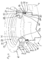
- the drain illustrated in the drawings is a floor drain 1 which has been provided with an extension ring 2 according to the present invention.
- the floor drain 1 and the extension ring 2, their various members and the various components therein may be entirely or partly made of metal, e.g. cast iron, stainless steel etc., or of suitable plastic materials.
- the floor drain 1 comprises a cup shaped inlet member 3 and a tubular laterally directed outlet member 4 which can be connected to an exit pipe (not shown).
- the inlet member 3 terminates at the top with a substantially vertically directed edge portion 5.
- the extension ring 2 comprises two members 6 and 7.
- the first member 6 includes means 8 for mounting of the extension ring 2 on the inlet member 3 of the floor drain 1, and first adjusting means 9 which cooperate with second adjusting means 10 on the second member 7 of the extension ring for vertical adjustment of the second member relative to the first member.
- said adjusting means 9, 10 which are described in more detail below in a preferred embodiment, said second member 7 can be set, after mounting of the extension ring 2 on the floor drain 1, relative to an existing or future level of the upper side of the underlayer (not shown) in which the drain is located.
- the first member 6 of the extension ring 2 is preferably designed as a substantially annular angle piece with at least two legs, wherein one leg is provided with mounting means and the other leg with said first adjusting means.
- said first member 6 of the extension ring 2 is substantially U-shaped.
- the first member 6 is thereby, in mounting position on the floor drain 1, located with the U open downwards over the vertical edge portion 5 of the inlet member 3 of the floor drain.
- the leg 11 with mounting means 8 extends in the mounting position substantially vertically on the outside of the vertical edge portion 5 of the floor drain 1, while the leg 12 with said first adjusting means 9 extends substantially vertically on the inside of said vertical edge portion.
- the leg 11 with the mounting means 8 is longer than the leg 12 with said first adjusting means 9.
- the first member 6 may also have another shape, adapted to the inlet member 3 of the floor drain 1.
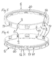
- said first member 6 is provided with an interruption (at A) in its substantially annular extent (see preferably figs. 5 and 6).
- the first member 6 is easily separated from and threaded onto the second member 7 until the adjusting means 9, 10 have been brought to cooperate with each other.
- the second member 7 of the extension ring 2 includes a substantially tubular and substantially vertically extending portion 13 which, depending on the position of said second member 7 after mounting of the extension ring on the floor drain 1, projects downwards more or less into the inlet member 3 of the floor drain, and a flange 14 which projects substantially radially outwards from an upper end of the tubular portion, said upper end projecting upwards from the inlet member.
- the flange 14 preferably has holes 15 for anchor means (not shown) for attaching the extension ring 2 to the underlayer for the floor drain 1.
- a section 13a of the vertically extending portion 13 is provided with a seat 16 for a clamping ring (not shown) on which a grating (not shown) is adapted to be located.
- Said second adjusting means 10 are provided on the vertically extending portion 13 of the second member 7 of the extension ring 2.
- the mounting means 8 on the first member 6 of the extension ring 2 are in the illustrated embodiment defined by recesses 17 in the outer leg 11.
- the inlet member 3 of the floor drain 1 has shoulders 18 on the outside of the upper vertical edge portion 5 for engagement in the recesses 17 when the extension ring 2 is mounted on the floor drain.
- the first member 6 can be attached, by a snap-in closure, to the floor drain 1 in a quick and easy manner.
- Mounting means of other types may also be provided within the scope of the invention and the inlet member 3 of the floor drain 1 can be designed in accordance therewith.
- said means are defined by a threaded coupling between said first and second members 6, 7 of the extension ring 2.
- Other types of couplings can be used within the scope of the invention, provided that the objects of the invention are achieved and precise vertical adjustment of the second member relative to the first member is permitted.
- the threaded coupling is at the illustrated embodiment defined by a radially inwards directed and helically extending flange 20 on the first member 6 of the extension ring 2, and by a radially outwards directed thread groove 21 in the second member 7 of the extension ring, engaged by said flange.
- the flange 20 is provided on the inside of the inner leg 12 of said first member 6 and the thread groove 21 on the outside of the vertically extending portion 13 of the second member 7 of the extension ring 2.
- the thread groove 21 is provided in flanges 22 located on the outside of the vertically extending portion 13 of said second member 7.
- the flanges 22 extend preferably in parallel in radial direction and are provided peripherally around the entire vertical portion 13.
- Said second member 7 of the extension ring 2 further comprises stops for limiting its vertical adjustment relative to the first member 6 of the extension ring.
- One stop for limiting the vertical adjustment upwards of the second member 7 relative to the first member 6 is defined by the thread groove 21 in the second member 7 for the flange 20 in the first member simply ending down below on the vertical portion 13 of said second member. By this measure, axial separation of the extension ring members 6, 7 is prevented.
- a suitable stop for limiting vertical adjustment downwards of the second member 7 relative to the first member 6, is defined by the underside 14a of the mounting flange 14 of the second member.
- Said second member 7 of the extension ring 2 is also designed or provided with at least one sealing means through which said second member cooperates with the inlet member 3 of the drain 1.
- the sealing means consists of a sealing ring 23 which is made integral with said second member 7 for sealing engagement of the inner side of the inlet member 3 of the drain 1.
- the sealing ring 23 is preferably made of another material, suitable for sealing purposes, e.g. a softer plastic material, than other parts of the second member 7 of the extension ring 2, but is designed not separable from said other parts.
- the sealing means may consist of a separate sealing ring which is provided on the second member 7 of the extension ring 2 and which is also made of a suitable material for sealing.
- the sealing means is designed or located preferably at the very bottom of the vertically extending portion 13 of the second member 7 of the extension ring 2, i.e. beneath the thread groove 21.
- the sealing means is in both embodiments preferably located in a groove or a recess 24 which thereby naturally is found preferably at the very bottom of the vertical portion 13 of the second member 7 of the extension ring 2.
- extension ring may be modified and altered within the scope of the following claims without departing from the idea and purpose of the invention.
- the extension ring may e.g. be used at other types of drains than floor drains and the drain may have other than laterally directed outlet members.
Landscapes
- Health & Medical Sciences (AREA)
- Life Sciences & Earth Sciences (AREA)
- Engineering & Computer Science (AREA)
- Hydrology & Water Resources (AREA)
- Public Health (AREA)
- Water Supply & Treatment (AREA)
- Sink And Installation For Waste Water (AREA)
- Clamps And Clips (AREA)
- Sewage (AREA)
Abstract
Description
- The present invention relates to an adjustable extension ring for a drain, wherein the extension ring comprises a first member and a second member cooperating therewith and wherein said first member includes means for mounting the extension ring on an inlet member of the drain.
- Extension rings are often kept in position only by means of a sealing, whereby no secure mounting or precise setting of the extension ring at the drain can be obtained. Alternatively, there may be a threaded coupling between the extension ring and the drain, whereby however, the production costs for the drain increase substantially partly because only a small part of the drains need to be taken out and provided with suitable threads and partly because of the working moment itself of providing the drain with suitable threads.
- An example of an adjustable extension ring substantially as defined above is shown and described in e.g.
SE 502 476 C2 - The object of the present invention has been to provide an extension ring which by simple means is easy to fix safely to a drain while it simultaneously permits precise setting thereof relative to the underlayer for the drain. Another object is to provide a drain for mounting of the extension ring which is less expensive and easier to manufacture.
- The adjustable extension ring according to the present invention is therefore characterized by the fact that the first member of the extension ring also includes first adjusting means which cooperate with second adjusting means on the second member of the extension ring for stepless adjustment of the second member in vertical direction relative to the first member, such that said second member, after mounting of the extension ring on the drain, can be set relative to an existing or future level of the upper side of the underlayer in which the drain is located.
- By providing the extension ring with said characterizing features, it is achieved that the extension ring, although it is immovably mounted on the drain, yet at the same time permits precise vertical adjustment thereof relative to the drain for adaptation to the upper side of the underlayer for the drain and that the secure mounting of the extension ring is maintained irrespective of the setting in vertical direction of the extension ring. Since the first member of the extension ring also, somewhat simplified, replaces the threads or other adjusting means on the drain, said drain will be less expensive and easier to manufacture.
- At the clamping ring with extension ring according e.g. to fig. 7 of
SE 502 476 C2 - The abovementioned and other objects according to the invention will be further described below with reference to the accompanying drawings, in which
- fig. 1 is a perspective view of an adjustable extension ring according to the invention mounted on a drain and located in a lower position;
- fig. 2 is a view corresponding to fig. 1, but shows the extension ring in an upper position;
- fig. 3 is a view corresponding to fig. 1, but with portions of the extension ring and the drain cut away;
- fig. 4 is a view corresponding to fig. 2, but with portions of the extension ring and the drain cut away;
- figs. 5 and 6 are perspective views of the first member of the extension ring; and
- figs. 7 and 8 are perspective views of the second member of the extension ring.
- The drain illustrated in the drawings is a
floor drain 1 which has been provided with anextension ring 2 according to the present invention. Thefloor drain 1 and theextension ring 2, their various members and the various components therein may be entirely or partly made of metal, e.g. cast iron, stainless steel etc., or of suitable plastic materials. - At the embodiment shown, the
floor drain 1 comprises a cup shapedinlet member 3 and a tubular laterally directedoutlet member 4 which can be connected to an exit pipe (not shown). At the illustrated embodiment, theinlet member 3 terminates at the top with a substantially vertically directededge portion 5. - According to the invention, the
extension ring 2 comprises twomembers first member 6 includes means 8 for mounting of theextension ring 2 on theinlet member 3 of thefloor drain 1, and first adjusting means 9 which cooperate with second adjusting means 10 on thesecond member 7 of the extension ring for vertical adjustment of the second member relative to the first member. By means of said adjusting means 9, 10, which are described in more detail below in a preferred embodiment, saidsecond member 7 can be set, after mounting of theextension ring 2 on thefloor drain 1, relative to an existing or future level of the upper side of the underlayer (not shown) in which the drain is located. - The
first member 6 of theextension ring 2 is preferably designed as a substantially annular angle piece with at least two legs, wherein one leg is provided with mounting means and the other leg with said first adjusting means. At the embodiment shown, saidfirst member 6 of theextension ring 2 is substantially U-shaped. Thefirst member 6 is thereby, in mounting position on thefloor drain 1, located with the U open downwards over thevertical edge portion 5 of theinlet member 3 of the floor drain. Theleg 11 with mounting means 8 extends in the mounting position substantially vertically on the outside of thevertical edge portion 5 of thefloor drain 1, while theleg 12 with said first adjusting means 9 extends substantially vertically on the inside of said vertical edge portion. At the embodiment shown, theleg 11 with the mounting means 8 is longer than theleg 12 with said first adjusting means 9. Thefirst member 6 may also have another shape, adapted to theinlet member 3 of thefloor drain 1. In order to facilitate the interconnection of the first andsecond members extension ring 2, saidfirst member 6 is provided with an interruption (at A) in its substantially annular extent (see preferably figs. 5 and 6). Hereby, thefirst member 6 is easily separated from and threaded onto thesecond member 7 until the adjusting means 9, 10 have been brought to cooperate with each other. - The
second member 7 of theextension ring 2 includes a substantially tubular and substantially vertically extendingportion 13 which, depending on the position of saidsecond member 7 after mounting of the extension ring on thefloor drain 1, projects downwards more or less into theinlet member 3 of the floor drain, and aflange 14 which projects substantially radially outwards from an upper end of the tubular portion, said upper end projecting upwards from the inlet member. Theflange 14 preferably hasholes 15 for anchor means (not shown) for attaching theextension ring 2 to the underlayer for thefloor drain 1. Asection 13a of the vertically extendingportion 13 is provided with aseat 16 for a clamping ring (not shown) on which a grating (not shown) is adapted to be located. Said second adjusting means 10 are provided on the vertically extendingportion 13 of thesecond member 7 of theextension ring 2. - The mounting means 8 on the
first member 6 of theextension ring 2 are in the illustrated embodiment defined byrecesses 17 in theouter leg 11. Theinlet member 3 of thefloor drain 1 hasshoulders 18 on the outside of the uppervertical edge portion 5 for engagement in therecesses 17 when theextension ring 2 is mounted on the floor drain. Hereby, thefirst member 6 can be attached, by a snap-in closure, to the floor drain 1 in a quick and easy manner. Mounting means of other types may also be provided within the scope of the invention and theinlet member 3 of thefloor drain 1 can be designed in accordance therewith. Between therecesses 17 but in the opposite end of theleg 11, seen in the longitudinal direction thereof, there are providedadditional recesses 19 for facilitating the attachment by means of a snap-in closure of thefirst member 6 and thereby, the mounting of theextension ring 2 on thefloor drain 1. - At the illustrated preferred embodiment of the first and second adjusting means 9, 10, said means are defined by a threaded coupling between said first and
second members extension ring 2. Other types of couplings can be used within the scope of the invention, provided that the objects of the invention are achieved and precise vertical adjustment of the second member relative to the first member is permitted. - The threaded coupling is at the illustrated embodiment defined by a radially inwards directed and helically extending
flange 20 on thefirst member 6 of theextension ring 2, and by a radially outwards directedthread groove 21 in thesecond member 7 of the extension ring, engaged by said flange. Thus, by rotating saidsecond member 7, stepless vertical adjustment of the second member relative to thefirst member 6 is permitted. Theflange 20 is provided on the inside of theinner leg 12 of saidfirst member 6 and thethread groove 21 on the outside of the vertically extendingportion 13 of thesecond member 7 of theextension ring 2. In order to get a slender, light and material saving construction, thethread groove 21 is provided inflanges 22 located on the outside of the vertically extendingportion 13 of saidsecond member 7. For manufacturing reasons, theflanges 22 extend preferably in parallel in radial direction and are provided peripherally around the entirevertical portion 13. - Said
second member 7 of theextension ring 2 further comprises stops for limiting its vertical adjustment relative to thefirst member 6 of the extension ring. One stop for limiting the vertical adjustment upwards of thesecond member 7 relative to thefirst member 6 is defined by thethread groove 21 in thesecond member 7 for theflange 20 in the first member simply ending down below on thevertical portion 13 of said second member. By this measure, axial separation of theextension ring members second member 7 relative to thefirst member 6, is defined by theunderside 14a of themounting flange 14 of the second member. - Said
second member 7 of theextension ring 2 is also designed or provided with at least one sealing means through which said second member cooperates with theinlet member 3 of thedrain 1. At the illustrated preferred embodiment, the sealing means consists of asealing ring 23 which is made integral with saidsecond member 7 for sealing engagement of the inner side of theinlet member 3 of thedrain 1. The sealingring 23 is preferably made of another material, suitable for sealing purposes, e.g. a softer plastic material, than other parts of thesecond member 7 of theextension ring 2, but is designed not separable from said other parts. As an alternative, the sealing means may consist of a separate sealing ring which is provided on thesecond member 7 of theextension ring 2 and which is also made of a suitable material for sealing. The sealing means is designed or located preferably at the very bottom of the vertically extendingportion 13 of thesecond member 7 of theextension ring 2, i.e. beneath thethread groove 21. The sealing means is in both embodiments preferably located in a groove or a recess 24 which thereby naturally is found preferably at the very bottom of thevertical portion 13 of thesecond member 7 of theextension ring 2. - It is obvious to a skilled person that beyond what is described above and illustrated in the drawings, the extension ring according to the present invention may be modified and altered within the scope of the following claims without departing from the idea and purpose of the invention. Thus, the extension ring may e.g. be used at other types of drains than floor drains and the drain may have other than laterally directed outlet members.
Claims (21)
- Adjustable extension ring for a drain, wherein the extension ring (2) comprises a first member (6) and a second member (7) cooperating therewith and wherein said first member includes means (8) for mounting the extension ring on an inlet member of the drain, characterized in that the first member (6) of the extension ring (2) also includes first adjusting means (9) which cooperate with second adjusting means (10) on the second member (7) of the extension ring for stepless adjustment of the second member in vertical direction relative to the first member, such that said second member, after mounting of the extension ring on the drain, can be set relative to an existing or future level of the upper side of the underlayer in which the drain is located.
- Extension ring according to claim 1, characterized in that said first member (6) of the extension ring (2) is designed as a substantially tubular angle piece with at least two legs (11, 12), wherein one leg (11) is provided with mounting means (8) and the other leg (12) with said first adjusting means (9).
- Extension ring according to claim 2, wherein the inlet member (3) of the drain terminates at the top with a substantially vertically directed edge portion (5), characterized in that said first member (6) of the extension ring (2) is substantially U-shaped and that in mounting position on the floor drain (1), said first member is located with the U open downwards over the vertical edge portion (5) of the inlet member (3) of the floor drain, such that the leg (11) with mounting means (8) extends in the mounting position substantially vertically on the outside of said vertical edge portion, while the leg (12) with said first adjusting means (9) extends substantially vertically on the inside of said vertical edge portion.
- Extension ring according to claim 3, characterized in that said mounting means (8) are defined by recesses (17) in the outer leg (11) and that the inlet member (3) of the drain (1) has shoulders (18) for engagement in the recesses when the extension ring (2) is mounted on the floor drain.
- Extension ring according to claim 4, characterized in that said shoulders (18) are provided on the outside of the upper vertical edge portion (5) of the inlet member (3).
- Extension ring according to any one of claims 1 to 5, characterized in that said second member (7) of the extension ring (2) includes a substantially tubular and substantially vertically extending portion (13) on which said second adjusting means (10) are located.
- Extension ring according to any one of claims 1 to 6, characterized in that said first and second adjusting means (9, 10) are defined by a threaded coupling (20, 21) between said first and second members (6, 7) of the extension ring (2).
- Extension ring according to claim 7, characterized in that the threaded coupling is defined by a radially inwards directed and helically extending flange (20) on the first member (6) of the extension ring (2) and by a radially outwards directed thread groove (21) in the second member (7) of the extension ring, engaged by said flange in order to permit, by rotation of said second member, stepless vertical adjustment of the second member relative to the first member.
- Extension ring according to claim 8, characterized in that the flange (20) is provided on the inside of the inner leg (12) of said first member (6) and the thread groove (21) on the outside of the vertically extending portion (13) of the second member (7) of the extension ring (2).
- Extension ring according to claim 9, characterized in that the thread groove (21) is provided in flanges (22) located on the outside of the vertically extending portion (13) of the second member (7) of the extension ring (2).
- Extension ring according to any one of claims 1 to 10, characterized in that said second member (7) of the extension ring (2) has stops for limiting its adjustment in vertical direction relative to the first member (6) of the extension ring.
- Extension ring according to claim 11, characterized in that a stop for limiting the vertical adjustment upwards of the second member (7) of the extension ring (2) relative to the first member (6) of said extension ring is defined by the thread groove (21) in the second member for the flange (20) in the first member ending down below on the vertical portion (13) of said second member.
- Extension ring according to claim 11 or 12, characterized in that a stop for limiting the vertical adjustment downwards of the second member (7) of the extension ring (2) relative to the first member (6) of said extension ring is defined by the underside (14a) of the mounting flange (14) of the second member.
- Extension ring according to any one of claims 2 to 13, characterized in that said first member (6) of the extension ring (2) has an interruption (A) in the annular extent thereof for facilitating its connection to the second member (7) of the extension ring.
- Extension ring according to claim 4 or 5, characterized in that between the recesses (17) for the shoulders (18) on the drain (1) there are provided, in the opposite end of the leg (11), seen in the longitudinal direction thereof, additional recesses (19) for facilitating the mounting of the extension ring (2) on the floor drain.
- Extension ring according to any one of claims 1 to 15, characterized in that said second member (7) of the extension ring (2) is designed or provided with at least one sealing means (23) through which, in mounting position on the drain (1), said second member cooperates with the inlet member (3) of the drain.
- Extension ring according to claim 16, characterized in that said sealing means consists of a sealing ring (23) which is made integral with said second member (7) of the extension ring (2) for, in mounting position on the drain (1), sealing engagement of the inner side of the inlet member (3) of the drain.
- Extension ring according to claim 16, characterized in that said sealing means consists of a sealing ring (23) which is provided on the second member (7) of the extension ring (2) for, in mounting position on the drain (1), sealing engagement of the inner side of the inlet member (3) of the drain.
- Extension ring according to any one of claims 16 to 18, characterized in that said sealing means (23) is designed or located beneath the thread groove (21) at the very bottom of the vertically extending portion (13) of the second member (7) of the extension ring (2).
- Extension ring according to any one of claims 16 to 19, characterized in that the second member (7) of the extension ring (2) has a groove or recess (24) for said sealing means (23).
- Extension ring according to any one of claims 1 to 20, characterized in that the second member (7) of the extension ring (2) has a seat (16) for a clamping ring.
Applications Claiming Priority (1)
| Application Number | Priority Date | Filing Date | Title |
|---|---|---|---|
| SE0501843A SE529981C2 (en) | 2005-08-22 | 2005-08-22 | Adjustable wastewater well |
Publications (2)
| Publication Number | Publication Date |
|---|---|
| EP1757743A2 true EP1757743A2 (en) | 2007-02-28 |
| EP1757743A3 EP1757743A3 (en) | 2013-06-26 |
Family
ID=37420988
Family Applications (1)
| Application Number | Title | Priority Date | Filing Date |
|---|---|---|---|
| EP06016387.0A Withdrawn EP1757743A3 (en) | 2005-08-22 | 2006-08-05 | Adjustable extension ring for drains |
Country Status (3)
| Country | Link |
|---|---|
| EP (1) | EP1757743A3 (en) |
| NO (1) | NO20063763L (en) |
| SE (1) | SE529981C2 (en) |
Cited By (1)
| Publication number | Priority date | Publication date | Assignee | Title |
|---|---|---|---|---|
| SE547074C2 (en) * | 2024-07-18 | 2025-04-15 | Purus Ab | Floor drain |
Citations (1)
| Publication number | Priority date | Publication date | Assignee | Title |
|---|---|---|---|---|
| SE502476C2 (en) | 1990-10-04 | 1995-10-30 | Jafo Ab | Clamping ring with extension ring for floor drains |
Family Cites Families (2)
| Publication number | Priority date | Publication date | Assignee | Title |
|---|---|---|---|---|
| DE3815365A1 (en) * | 1987-05-05 | 1989-08-17 | Hoos Hubert Dipl Ing Fh | Installation part for shafts and drainage parts and apparatus for handling the same |
| SE506406C2 (en) * | 1993-02-24 | 1997-12-15 | Sjoebo Bruk Ab | Raising device for floor wells |
-
2005
- 2005-08-22 SE SE0501843A patent/SE529981C2/en not_active IP Right Cessation
-
2006
- 2006-08-05 EP EP06016387.0A patent/EP1757743A3/en not_active Withdrawn
- 2006-08-22 NO NO20063763A patent/NO20063763L/en not_active Application Discontinuation
Patent Citations (1)
| Publication number | Priority date | Publication date | Assignee | Title |
|---|---|---|---|---|
| SE502476C2 (en) | 1990-10-04 | 1995-10-30 | Jafo Ab | Clamping ring with extension ring for floor drains |
Cited By (2)
| Publication number | Priority date | Publication date | Assignee | Title |
|---|---|---|---|---|
| SE547074C2 (en) * | 2024-07-18 | 2025-04-15 | Purus Ab | Floor drain |
| SE2430381A1 (en) * | 2024-07-18 | 2025-04-15 | Purus Ab | Floor drain |
Also Published As
| Publication number | Publication date |
|---|---|
| SE529981C2 (en) | 2008-01-22 |
| SE0501843L (en) | 2007-02-23 |
| NO20063763L (en) | 2007-02-23 |
| EP1757743A3 (en) | 2013-06-26 |
Similar Documents
| Publication | Publication Date | Title |
|---|---|---|
| US9060656B2 (en) | Drain stopper assembly | |
| US20080169228A1 (en) | Filter assembly | |
| CA2831508C (en) | Rough-in adapter | |
| US9493933B2 (en) | Pedestal strainer for a sink drain | |
| US11359362B2 (en) | Ligature resistant floor drain and grate | |
| US9139996B2 (en) | Removable locking floor sink drain screen for enlarged opening | |
| AU2011203575B2 (en) | Filter and Filter Assembly | |
| US4943100A (en) | Drain suited for installation in wooden floors | |
| US3982703A (en) | Mounting assembly for food waste disposer | |
| US20130061387A1 (en) | Shower drain cover | |
| EP1983115B1 (en) | A waste water outlet unit | |
| CA3064384A1 (en) | Sink and drain for sink | |
| US9021628B2 (en) | Drain, in particular for floor level showers | |
| GB2475413A (en) | Clogging resistant drain | |
| US10196806B2 (en) | Floor sink strainer and assembly | |
| US6557229B1 (en) | Positioning tool for installing food waste disposers | |
| CA3111828C (en) | Floor drain | |
| EP0612893B1 (en) | Adjustable elevation device for floor drains | |
| US9637908B2 (en) | Drain assembly | |
| US20250075488A1 (en) | Telescoping adjustable drain | |
| EP1433904A1 (en) | Drainage device for shower tray | |
| JP5760467B2 (en) | Bowl equipment | |
| CN114855978B (en) | Drain pipe floor drain with adjustable height of insect and odor-proof device | |
| EP2112281A1 (en) | Pillar-like faucet | |
| CA2845436A1 (en) | Decorative pop-up flange replacement |
Legal Events
| Date | Code | Title | Description |
|---|---|---|---|
| PUAI | Public reference made under article 153(3) epc to a published international application that has entered the european phase |
Free format text: ORIGINAL CODE: 0009012 |
|
| AK | Designated contracting states |
Kind code of ref document: A2 Designated state(s): AT BE BG CH CY CZ DE DK EE ES FI FR GB GR HU IE IS IT LI LT LU LV MC NL PL PT RO SE SI SK TR |
|
| AX | Request for extension of the european patent |
Extension state: AL BA HR MK YU |
|
| PUAL | Search report despatched |
Free format text: ORIGINAL CODE: 0009013 |
|
| AK | Designated contracting states |
Kind code of ref document: A3 Designated state(s): AT BE BG CH CY CZ DE DK EE ES FI FR GB GR HU IE IS IT LI LT LU LV MC NL PL PT RO SE SI SK TR |
|
| AX | Request for extension of the european patent |
Extension state: AL BA HR MK RS |
|
| RIC1 | Information provided on ipc code assigned before grant |
Ipc: E03F 5/04 20060101AFI20130517BHEP |
|
| AKX | Designation fees paid |
Designated state(s): AT BE BG CH CY CZ DE DK EE ES FI FR GB GR HU IE IS IT LI LT LU LV MC NL PL PT RO SE SI SK TR |
|
| STAA | Information on the status of an ep patent application or granted ep patent |
Free format text: STATUS: THE APPLICATION IS DEEMED TO BE WITHDRAWN |
|
| 18D | Application deemed to be withdrawn |
Effective date: 20140103 |