EP1757548A1 - Single facer web member position adjusting device, and single facer sizing device - Google Patents
Single facer web member position adjusting device, and single facer sizing device Download PDFInfo
- Publication number
- EP1757548A1 EP1757548A1 EP04730030A EP04730030A EP1757548A1 EP 1757548 A1 EP1757548 A1 EP 1757548A1 EP 04730030 A EP04730030 A EP 04730030A EP 04730030 A EP04730030 A EP 04730030A EP 1757548 A1 EP1757548 A1 EP 1757548A1
- Authority
- EP
- European Patent Office
- Prior art keywords
- core
- paste
- roll
- web
- liner
- Prior art date
- Legal status (The legal status is an assumption and is not a legal conclusion. Google has not performed a legal analysis and makes no representation as to the accuracy of the status listed.)
- Withdrawn
Links
Images










Classifications
-
- B—PERFORMING OPERATIONS; TRANSPORTING
- B65—CONVEYING; PACKING; STORING; HANDLING THIN OR FILAMENTARY MATERIAL
- B65H—HANDLING THIN OR FILAMENTARY MATERIAL, e.g. SHEETS, WEBS, CABLES
- B65H39/00—Associating, collating, or gathering articles or webs
- B65H39/16—Associating two or more webs
-
- B—PERFORMING OPERATIONS; TRANSPORTING
- B31—MAKING ARTICLES OF PAPER, CARDBOARD OR MATERIAL WORKED IN A MANNER ANALOGOUS TO PAPER; WORKING PAPER, CARDBOARD OR MATERIAL WORKED IN A MANNER ANALOGOUS TO PAPER
- B31F—MECHANICAL WORKING OR DEFORMATION OF PAPER, CARDBOARD OR MATERIAL WORKED IN A MANNER ANALOGOUS TO PAPER
- B31F1/00—Mechanical deformation without removing material, e.g. in combination with laminating
- B31F1/20—Corrugating; Corrugating combined with laminating to other layers
- B31F1/24—Making webs in which the channel of each corrugation is transverse to the web feed
- B31F1/26—Making webs in which the channel of each corrugation is transverse to the web feed by interengaging toothed cylinders cylinder constructions
- B31F1/28—Making webs in which the channel of each corrugation is transverse to the web feed by interengaging toothed cylinders cylinder constructions combined with uniting the corrugated webs to flat webs ; Making double-faced corrugated cardboard
- B31F1/2831—Control
- B31F1/2836—Guiding, e.g. edge alignment; Tensioning
-
- B—PERFORMING OPERATIONS; TRANSPORTING
- B65—CONVEYING; PACKING; STORING; HANDLING THIN OR FILAMENTARY MATERIAL
- B65H—HANDLING THIN OR FILAMENTARY MATERIAL, e.g. SHEETS, WEBS, CABLES
- B65H23/00—Registering, tensioning, smoothing or guiding webs
- B65H23/02—Registering, tensioning, smoothing or guiding webs transversely
- B65H23/032—Controlling transverse register of web
-
- B—PERFORMING OPERATIONS; TRANSPORTING
- B65—CONVEYING; PACKING; STORING; HANDLING THIN OR FILAMENTARY MATERIAL
- B65H—HANDLING THIN OR FILAMENTARY MATERIAL, e.g. SHEETS, WEBS, CABLES
- B65H23/00—Registering, tensioning, smoothing or guiding webs
- B65H23/02—Registering, tensioning, smoothing or guiding webs transversely
- B65H23/032—Controlling transverse register of web
- B65H23/0326—Controlling transverse register of web by moving the unwinding device
-
- B—PERFORMING OPERATIONS; TRANSPORTING
- B65—CONVEYING; PACKING; STORING; HANDLING THIN OR FILAMENTARY MATERIAL
- B65H—HANDLING THIN OR FILAMENTARY MATERIAL, e.g. SHEETS, WEBS, CABLES
- B65H2403/00—Power transmission; Driving means
- B65H2403/50—Driving mechanisms
- B65H2403/52—Translation screw-thread mechanisms
-
- B—PERFORMING OPERATIONS; TRANSPORTING
- B65—CONVEYING; PACKING; STORING; HANDLING THIN OR FILAMENTARY MATERIAL
- B65H—HANDLING THIN OR FILAMENTARY MATERIAL, e.g. SHEETS, WEBS, CABLES
- B65H2406/00—Means using fluid
- B65H2406/30—Suction means
- B65H2406/36—Means for producing, distributing or controlling suction
- B65H2406/363—Means for producing, distributing or controlling suction adjusting or controlling distribution of vacuum for a plurality of suction means
Definitions
- the present invention relates to single facers, and more particularly to alignment techniques of web mediums (a liner and a core) that are to be stuck together in a single facer and to alignment techniques of the paste dams of a paster.
- a single faced corrugated sheet is made by corrugating a core that is one of two web mediums, then pasting the ridges of the corrugated core, and sticking a liner that is the other web medium on the pasted surface of the core.
- the position of sticking a core and a liner together is manually adjusted by an operator. The operator checks the pasted state of the core and the liner. When a paper edge of the liner is out of alignment with a paper edge of the core, they are aligned with each other by moving in the width direction at least either a mill roll stand supporting a roll of core or a mill roll stand supporting a roll of liner.
- a core and a liner are stuck together with paste, and a single facer is equipped with a paster as a device for supplying paste.
- the paster is normally equipped with a paste reservoir for storing paste, a pasting roll for causing paste to adhere to the ridges of a corrugated core, and two paste dams. Part of the outer periphery of the pasting roll is immersed in the paste stored within the paste reservoir, and the width of paste adhering to the pasting roll is regulated by damming the paste within the paste reservoir in the machine width direction with the two paste dams.
- the paste dams can be moved in the machine width direction, and the width of paste adhering to the pasting roll can be varied by changing the positions of the paste dams.
- a protruding region of each web medium from the surfaces stuck together is a waste region that cannot be utilized as corrugated cardboard. If such a protruding region is increased, waste of paper consumption will be caused. Also, if a protruding region of the core from the surfaces stuck together is increased, waste of paste consumption will be caused.
- Patent Document 1 a technique disclosed in Japanese Laid-Open Patent Publication No. Sho 62-55125 (hereinafter referred to as Patent Document 1) adjusts a position at which the ridges of a corrugated core are pasted. More specifically, the right paper edges of two web mediums are compared with each other and the left paper edges are compared with each other, and the positions of the right and left paste dams are adjusted so as to be aligned with the inner paper edges. The pasting positions are determined by the positions of the right and left paste dams. Therefore, if the positions of the right and left paste dams are aligned with the inner paper edges, there is no possibility that the pasted region of the core will protrude from the surfaces stuck together. As a result, waste of paste consumption can be prevented and the occurrence of stains and inferior goods due to extra adhesion of paste can be avoided.
- Patent Document 2 Japanese Laid-Open Patent Publication No. Hei 8-258187 (hereinafter referred to as Patent Document 2) and Japanese Laid-Open Patent Publication No. Hei 7-100976 (hereinafter referred to as Patent Document 3), there is also known a technique for always obtaining an optimum paste width by detecting the position of a paper edge of a core before pasting by a position detecting device such as a photoelectric tube, and automatically adjusting the position in the machine width direction of a paste dam so as to be aligned with the detected paper edge position.
- a position detecting device such as a photoelectric tube
- the technique disclosed in the Patent Document 1 can prevent the pasted surface of a core from protruding from the surfaces stuck together, but cannot adjust the misalignment in the width direction between two web mediums. For this reason, when there is a great misalignment between web mediums, a protruding region of each web medium from the surfaces stuck together will become great and therefore waste of paper consumption will become great.
- the present invention has been made in view of the aforementioned problems. Accordingly, it is the object of the present invention to provide a web-position adjustment apparatus and paster in a single facer that are capable of reducing waste of paper consumption and paste consumption.
- the present invention has the following means in order to solve the aforementioned problems.
- a web-position adjustment apparatus of the present invention is equipped with displacement means for changing a travel position of at least one of the two web mediums.
- Position detection means detects the positions in a machine width direction of the two web mediums. Based on the result of detection, control means is constructed to automatically control the displacement means so that one of the two web mediums is arranged inside the other web medium.
- the aforementioned position detection means preferably employs an image pick-up device such as a charge-coupled device (CCD) camera, etc.
- an image pick-up device such as a charge-coupled device (CCD) camera, etc.
- CCD charge-coupled device
- Each web medium is photographed with an image pick-up device arranged above the path of travel of each web medium, and the position in the machine width direction of each web medium is detected by processing the photographed image by image processing means.
- image processing means In the case of an image pick-up device whose angle of field is wide, image distortion will occur at the edge portion of the visual field. Therefore, it is preferable that the image process means have a function of correcting the distortion of an image photographed with an image pick-up device.
- the position detection means preferably detects the positions of the two web mediums, at positions that are above heating rolls arranged very near to a location where the two web mediums are stuck together, or above downstream sides from the heating rolls. Because the paper width of a web medium contracts due to the heat from the heating roll, the position in the machine width direction of the web medium changes before and after the heating roll. Therefore, if position detection is performed at a position that is above the heating roll arranged very near to a location where the two web mediums are stuck together, or above a downstream side from the heating roll, it becomes possible to accurately detect the position in the machine width direction of each web medium at the time of alignment. It is more preferably to detect the position of a web medium above the heating roll. Since the flapping of a web medium can be prevented on the heating roll, more accurate detection becomes possible.
- the aforementioned displacement means may be means for moving a base paper roll of web medium in the machine width direction or may be means for rotating the base paper roll in a plane parallel to the axis of the web roll. If the position in the machine width direction of the base paper roll is changed, the travel position of the web medium also slides in the moving direction of thebasepaperroll. Also, if the base paper roll is rotated to form an angle between the sending-out direction of the web medium from the base paper roll and the line traveling direction, the travel position of the web medium is gradually varied in the machine width direction.
- each web medium is preset by previously acquiring data about the position in the machine width direction of each web medium (e.g., data about paper width, data about expansion and contraction ratios relative to moisture and temperature, etc.), and controlling the displacement means in dependence on the acquired data by the control means so that one of two web mediums is arranged inside the other web medium. In this manner, it becomes possible to early adjust the travel position of each web medium to a proper travel position in the feedback control after the start of operation, and waste of paper consumption and paste consumption can be reduced.
- data about the position in the machine width direction of each web medium e.g., data about paper width, data about expansion and contraction ratios relative to moisture and temperature, etc.
- paper-edge position detection means detects the position of a paper edge of a core at a position that is above a heating roll arranged very near to a pasting roll or above a downstream side from the heating roll.
- control means that controls movement means for moving paste dams in the machine width direction, a deviation between the paper edge position detected by paper-edge position detection means and the position of the paste dam detected by paste-dam position detection means is calculated, and the movement means is controlled in a direction where the deviation becomes zero.
- the paper width of a core contracts due to the heat from the heating roll, the position in the machine width direction of the core changes before and after the heating roll. Therefore, if the position of a paper edge of the core is detected at a position that is above the heating roll arranged very near to a pasting roll, or above a downstream side from the heating roll, the paper edge position of the core can be accurately detected when the core is pasted. In this manner, the position of the paste dam can be accurately adjusted so as to align with the paper edge position of the core, and the occurrence of stains and inferior goods due to extra paste protruding from the core can be prevented. In addition, waste of paper consumption and paste consumption can be reduced. It is more preferably to detect the paper edge position of the core above the heating roll. Since the flapping of the core can be prevented on the heating roll, more accurate detection of the paper edge position of the core becomes possible.
- the paper-edge position detection means preferably employs an image pick-up device such as a CCD camera, etc.
- a core is photographed with an image pick-up device arranged above the path of travel of the core, and the position in the machine width direction of the core is detected by processing the photographed image by image processing means.
- image processing means In the case of an image pick-up device whose angle of field is wide, image distortion will occur at the edge portion of the visual field. Therefore, it is preferable that the image process means have a function of correcting the distortion of an image photographed with an image pick-up device.
- the position of the paste dam is preset by previously acquiring data about the position in the machine width direction of the core (e. g. , data about paper width, data about expansion and contraction ratios relative to moisture and temperature, etc.), and controlling the movement means in dependence on the acquired data by the control means. In this manner, it becomes possible to early adjust the position of the paste dam to a proper travel position in the feedback control after the start of operation, and waste of paper consumption and paste consumption can be reduced.
- data about the position in the machine width direction of the core e. g. , data about paper width, data about expansion and contraction ratios relative to moisture and temperature, etc.
- the control means preferably controls the movement means so that the paste dams are accelerated in a high acceleration rate at the start of movement and are decelerated and stopped in a low deceleration rate at the stop of movement.
- the variable speed control can be easily realized by applying inverter control. If the variable speed control is thus performed, the paste dams can be moved to desired positions with a high degree of accuracy.
- the position of a paste dam may be adjusted so as to align with the shifted position of the core.
- the position of a dam is adjusted.
- center-position detection means first detects the center position in the width direction of the core at a position that is above the heating roll arranged very near to the pasting roll or above a downstream side from the heating roll.
- the control means a deviation between the center position detected by the center-position detection means and the reference position is calculated, and displacement means for changing the travel position of the core is controlled in a direction where the deviation becomes zero.
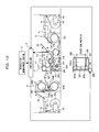
- Fig. 1(a) is a schematic diagram showing the single facer and vicinity of a corrugator to which a web-position adjustment apparatus according to a first embodiment of the present invention is applied.
- a liner 20 that is one of two web mediums to be stuck together at a single facer 11 is supported in the form of a roll (hereinafter referred to as a liner roll) 201 by a liner mill roll stand 13.
- a core 21 that is the other web medium is supported in the form of a roll (hereinafter referred to as a core roll) 211 by a core mill roll stand 14.
- the liner mill roll stand 13 is equipped with a pair of arms 131 and 131, by which the opposite ends of the liner roll 201 are rotatably supported.
- the arms 131, 131 are slidablly attached in the direction of the width of the machine to a shaft 132 secured on a floor.
- the arms 131, 131 are engaged by a ball screw 133 extending in the machine width direction, the rear end of which is formed integrally with the rod of a hydraulic cylinder 136.
- the position of the hydraulic cylinder 136 is fixed with respect to the floor. If the hydraulic cylinder 136 is actuated, the liner roll 201 can be moved in the machine width direction integrally with the ball screw 133 and arms 131, 131.
- the ball screw 133 is also connected with a motor 134 through a gear 135. If the ball screw 133 is rotated by the motor 134, the liner roll 201 can also be moved in the machine width direction along with the arms 131, 131.
- the construction of the core mill roll stand 14 is the same as that of the liner mill roll stand 13. As shown in Fig. 1(c), the opposite ends of the core roll 211 are rotatably supported by arms 141, 141.
- the arms 141, 141 are slidablly attached in the machine width direction to a shaft 142 secured on the floor.
- the arms 141, 141 are engaged by a ball screw 143 extending in the machine width direction, the rear end of which is formed integrally with the rod of a hydraulic cylinder 146. If the hydraulic cylinder 146 is actuated, the core roll 211 can be moved in the machine width direction.
- the ball screw 143 is also connected with a motor 144 through a gear 145. If the ball screw 143 is rotated by the motor 144, the core roll 211 can also be moved in the machine width direction.
- the liner 20 is supplied from the aforementioned liner mill roll stand 13 through a liner pre-heater 10 and to the single facer 11. Also, the core 21 is supplied from the aforementioned core mill roll stand 14 through a core pre-heater 12 and to the single facer 11.
- the liner pre-heater 10 is equipped with liner heating rolls 101A, 101B disposed in two stages vertically.
- the liner heating rolls 101A, 101B are heated to a predetermined temperature by supplying steam to the interiors.
- the liner 20, guided in order by guide rolls 105, 104A, 106, and 104B, is wound around the peripheral surfaces of the liner heating rolls 101A, 101B and is preheated by the liner heating rolls 101A, 101B.
- the core pre-heater 12 has the same construction as the liner pre-heater 10 and is equipped with a core heating roll 121 heated to a predetermined temperature by supplying steam to the interior.
- the core 21 guided by a guide roll 124 is wound around the peripheral surface of the core heating roll 121 and is preheated by the core heating roll 121.
- the single facer 11 is equipped with a pressure belt 113 looped between a belt roll 111 and a tension roll 112; an upper roll 114 with a corrugated surface pressed against the pressure belt 113; and a lower roll 115 with a corrugated surface meshing with the corrugated surface of the upper roll 114.
- the back liner 20 heated by the liner pre-heater 10 is wound around the liner preheating roll 117 and is preheated. Then, the back liner 20 is guided by the bet roll 111 and is conveyed between the nipping portions of the pressure belt 113 and upper roll 114 along with the pressure belt 113.
- the core 21 heated by the core pre-heater 12 is wound around the core pre-heating roll 118 and is preheated. Then, the core 21 is corrugated by the meshing portions of the upper roll 114 and lower roll 115. Next, the core 21 is guided by the upper roll 114 and is conveyed between the nipping portions of the pressure belt 113 and upper roll 114.
- a paster 116 is arranged near the upper roll 114 and comprises a paste reservoir 116a, a pasting roll 116b for pasting the core 21 conveyed by the upper roll 114, a doctor roll 116c for adjusting the amount of paste 30 applied to the peripheral surface of the pasting roll 116b, and a scraper 116d for removing the paste 30 from the doctor roll 116c.
- the core 21 corrugated by the meshing portions of the upper and lower rolls 114 and 115 is pasted at the ridges of the corrugated surface and is stuck on the liner 20 by the nipping portions of the pressure belt 113 and upper roll 114. In this manner, there is formed a single faced corrugated sheet 22.
- the web-position adjustment apparatus comprises the hydraulic cylinder 136 of the liner mill roll stand 13, the hydraulic cylinder 146 of the core mill roll stand 14, two charge-coupled device (CCD) cameras 3 and 4, and a controller 1.
- the hydraulic cylinder 136 functions as displacement means for moving the base paper roll 201 in the machine width direction to change the travel position of the liner 20.
- the hydraulic cylinder 146 functions as displacement means for moving the base paper roll 211 in the machine width direction to change the travel position of the core 21.
- the CCD cameras 3, 4 are image pick-up devices for detecting the positions in the machine width direction of the liner 20 and core 21.
- the CCD camera 4 for picking up the image of the core 21 is arranged above the core preheating roll 118 within the single facer 11.
- the paper width of the core 21 contracts due to heating at the core preheating roll 118, so the position in the machine-width direction changes before and after the core preheating roll 118.
- the CCD camera 4 is arranged above the core preheating roll 118 and picks up the image of the core 21 placed on the core preheating roll 118, the position in the machine width direction of the core 21 can be accurately detected.
- the CCD camera 4 may be arranged on a downstream side from the core preheating roll 118.
- the image of the core 21 is picked up above the core preheating roll 118, there is no flapping of the core 21 and therefore the position in the machine width direction of the core 21 can be more accurately detected.
- space to arrange the CCD camera 3 is limited because a distance from the liner preheating roll 117 to the belt roll 111 is short, so the CCD camera 3 is arranged above the path of travel between the liner pre-heater 10 and the single facer 11.
- the images picked up by the CCD cameras 3, 4 are transmitted to the controller 1.
- the controller 1 functions as image processing means for processing the images picked up by the CCD cameras 3, 4 and as feedback control means for controlling the hydraulic cylinders 136, 146.
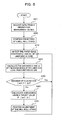
- Fig. 2 is a flowchart showing these functions of the controller 1.
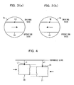
- the position adjustment control of the liner 20 and core 21 by the controller 1 will hereinafter be described in reference to Figs. 3 (a) and 3 (b) and Fig. 4 according to the flowchart shown in Fig. 2.
- the controller 1 detects the paper edge L1 on the driving side (back side of Fig. 1(a) where driving systems, such as motors, gears, etc. , are installed) of the liner 20 from the image picked up by the CCD camera 3 and, as shown in Fig. 3 (b) , detects the paper edge M1 on the driving side of the core 21 from the image picked up by the CCD camera 4.
- the visual fields 3a, 4a of the CCD cameras 3, 4 are fixed (for the above, step A10).
- the controller 1 calculates a distance 11 between an imaginary reference line and the paper edge L1 and a distance m1 between the imaginary reference line and the paper edge M1, as shown in Fig. 4. Since the CCD cameras 3, 4 have a wide angle of field, distortion will occur in the edge portions of the visual fields 3a, 4a. Therefore, the controller 1 corrects image distortion employing a correction curve or correction function and then calculates the distances 11 and m1 (for the above, step A20).
- the controller 1 calculates the absolute value of the difference between the two distances (m1 - 11) and decides whether or not the calculated value is within a target value (allowable value) ⁇ (preferably, 0) (step A30). If the difference in distance is within the target value, the controller 1 returns to step A10. If the difference in distance exceeds the target value, the controller 1 calculates a deviation between the difference in distance and the target value (step A40). The controller 1 controls the hydraulic cylinder 136 or 146 in dependence on the calculated deviation, moves the liner roll 201 or core roll 211 in the machine width direction, and adjusts the travel direction of the liner 20 or core 21 in a direction where the aforementioned deviation becomes zero (step A50).
- the hydraulic cylinders 136, 146 may be both actuated, but one of the two can be actuated with the other always fixed. Also, if the deviation is positive the hydraulic cylinder 136 may be actuated and if the deviation is negative the hydraulic cylinder 146 may be actuated. That is, the hydraulic cylinder to be actuated may be decided according to the direction of the deviation.
- the aforementioned feedback control may be combined with feedforward control, as shown in Fig. 5.
- the controller 1 first receives data about the positions in the machine width directions of the liner 20 and core 21 from a production management device 2 (step A01).
- the data about the positions in the machine width directions includes, for example, the paper widths of the liner 20 and core 21, expansion and contraction ratios for each paper type relative to moisture and temperature, moisture contents and temperature of web mediums just before they are stuck together, etc.
- the controller 1 predicts a deviation between the paper edge of the liner 20 and the paper edge of the core 21 from the received data, controls the hydraulic cylinder 136 or 14 6 in dependence on the predicted deviation and moves the liner roll 201 or core roll 211 in the machine width direction, and presets the travel positions of the liner 20 and core 21 (step A02). Note that in the initial state before the start of feedforward control, the liner roll 201 and core roll 211 are assumed to be set at predetermined initial positions. After the presetting, operation is started to perform the aforementioned feedback control (steps A10 to A50).
- a second embodiment of the present invention will be described with reference to Figs. 6, 7(a), 7(b), and 8.
- This method differs from the first embodiment in the function of the controller 1, that is, position adjustment method of two web mediums.
- the construction other than the function of the controller 1 is the same as the first embodiment.
- the entire construction is represented in Figs. 1(a), 1(b), and 1(c), as with the first embodiment.
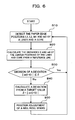
- Position adjustment control of the liner 20 and core 21 according to this embodiment will be described in reference to Figs. 7(a), 7(b), and 8 according to a flowchart shown in Fig. 6.
- the controller 1 detects both paper edges L1 and L2 of the liner 20 from the image picked up by the CCD camera 3 and, as shown in Fig. 7(b), detects both paper edges M1 and M2 of the core 21 from the image picked up by the CCD camera 4 (for the above, step B10).
- the controller 1 corrects image distortion employing a correction curve or correction function. Thereafter, from the positions of the paper edges L1 and L2 of the liner 20 within the visual field 3a and the positions of the paper edges M1 and M2 of the core 21 within the visual field 4a, the controller 1 respectively calculates the distance 11, 12, m1 and m2 between an imaginary reference line and each of the paper edges L1, L2, M1, and M2, as shown in Fig. 8.
- the controller 1 calculates the absolute value of the difference between the two distances (m0 - 10) and decides whether or not the calculated value is within a target value (allowable value) ⁇ (preferably, 0) (step B30). If the difference in distance is within the target value, the controller 1 returns to step B10. If the difference in distance exceeds the target value, the controller 1 calculates a deviation between the difference in distance and the target value (step B40). The controller 1 controls the hydraulic cylinder 136 or 146 in dependence on the calculated deviation, moves the liner roll 201 or core roll 211 in the machine width direction, and adjusts the travel direction of the liner 20 or core 21 in a direction where the aforementioned deviation becomes zero (step B50).
- the travel positions of the liner 20 and core 21 may be preset before the start of operation by performing feedforward control prior to the aforementioned feedback control.
- a third embodiment of the present invention will be described in reference to Figs. 9, 10, 11(a), 11(b), 11(c), and 11(d).
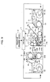
- a web-position adjustment apparatus employs a single CCD camera 5 as an image pick-up device for detecting positions in the machine width direction of a liner 20 and a core 21.
- the CCD camera 5 is arranged above the path of travel of a single faced corrugated sheet 22 manufactured by sticking the liner 20 and core 21 together. Note in Fig. 9 that the same parts as the first embodiment are given the same reference numbers.
- Fig. 10 is a flowchart showing the function of the controller 1. Position adjustment control of the liner 20 and core 21 in this embodiment will be described in reference to Figs. 11(a), 11(b), 11(c), and 11(d) according to the flowchart shown in Fig. 10.
- the controller detects the paper edges L1 and L2 of the liner 20 and the paper edges M1 and M2 of the core 21 from the image picked up by the CCD camera 5 (step C10).
- the surface of the liner 20 is smooth, while the corrugated surface of the core 1 has alternate ridges and grooves. Therefore, since the liner 20 and the core 21 distinctly differ in luminance distribution, the liner 20 can be distinctly discriminated from the core 21 by image processing.
- Figs. 11 (a), 11 (b), 11 (c), and 11 (d) there are four cases in the positional relationship between the paper edges L1 and L2 of the liner 20 and the paper edges M1 and M2 of the core 21, detected in step C10.
- Fig. 11 (a) shows the first case in which the both paper edges M1 and M2 of the core 21 protrude from both paper edges L1 and L2 of the liner 20.
- Fig. 11(b) shows the second case in which the paper edge M1 of the core 21 protrudes from the paper edge L1 on the driving side of the liner 20.
- Fig. 11(c) shows the third case in which the paper edge M2 of the core 21 protrudes from the paper edge L2 on the operating side of the liner 20.
- Fig. 11 (d) shows the fourth case in which the core 21 is hidden inside the paper edges L1 and L2 of the liner 20.
- the controller 1 decides which of the aforementioned four cases corresponds to the positional relationship between the paper edges L1 and L2 of the liner 20 and the paper edges M1 and M2 of the core 21 (step C20), photographed with the CCD camera 5 and performs control according to the decided case.
- the liner 20 is arranged inside the core 21
- the core 21 is arranged inside the liner 20.
- a protruding region of the liner 20 or core 21 from the surfaces stuck together has reached a minimum, so there is no need to adjust the travel positions of the liner 20 and core 21. Therefore, in these cases, the controller 1 returns to step C10.
- the controller controls the hydraulic cylinder 136 or 146 so that the paper edge L1 of the liner 20 and the paper edge M1 of the core 21 are aligned with each other, and moves the liner roll 201 or core roll 211 in the machine width direction to adjust the travel position of the liner 20 or core 21.
- the controller controls the hydraulic cylinder 136 or 146 so that the paper edge L1 of the liner 20 and the paper edge M1 of the core 21 are aligned with each other, and moves the liner roll 201 or core roll 211 in the machine width direction to adjust the travel position of the liner 20 or core 21.
- the third case shown in Fig. 11 (c) there is a possibility that the paper edge M1 of the core 21 will be arranged inside the paper edge L1 of the liner 20.
- the controller 1 moves the liner roll 201 or core roll 211 in the machine width direction so that the paper edge L2 of the liner 20 and the paper edge M2 of the core 21 are aligned with each other, and adjusts the travel position of the liner 20 or core 21.
- the aforementioned processing steps may be performed in the same manner as the steps A20 to A50 described in the first embodiment (for the above, step C30).
- the single CCD camera 5 is used, so costs can be reduced compared with the first and second embodiments.
- whether to adjust the travel position of the liner 20 or core 21 is decided from the positional relationship between the liner 20 and the core 21 actually stuck together, so more accurate adjustments become possible.
- the travel positions of the liner 20 and core 21 may be preset before the start of operation by performing feedforward control prior to the aforementioned feedback control.
- Fig. 12 is a schematic diagram showing the single facer and vicinity of a corrugator equipped with a paster constructed according to a fourth embodiment of the present invention.
- a liner 20 that is one of two web mediums to be stuck together at a single facer 11 is supported in the form of a roll (hereinafter referred to as a liner roll) 201 by a liner mill roll stand 13.
- a core 21 that is the other web medium is supported in the form of a roll (hereinafter referred to as a core roll) 211 by a core mill roll stand 14.
- the liner 20 is supplied from the liner mill roll stand 13 through a liner pre-heater 10 and to the single facer 11.
- the core 21 is supplied from the core mill roll stand 14 through a core pre-heater 12 and to the single facer 11.
- the liner pre-heater 10 is equipped with liner heating rolls 101A, 101B disposed in two stages vertically.
- the liner heating rolls 101A, 101B are heated to a predetermined temperature by supplying steam to the interiors.
- the liner 20, guided in order by guide rolls 105, 104A, 106, and 104B, is wound around the peripheral surfaces of the liner heating rolls 101A, 101B and is preheated by the liner heating rolls 101A, 101B.
- the core pre-heater 12 has the same construction as the liner pre-heater 10 and is equipped with a core heating roll 121 heated to a predetermined temperature by supplying steam to the interior.
- the core 21 guided by a guide roll 124 is wound around the peripheral surface of the core heating roll 121 and is preheated by the core heating roll 121.
- the single facer 11 is equipped with a pressure belt 113 looped between a belt roll 111 and a tension roll 112; an upper roll 114 with a corrugated surface pressed against the pressure belt 113; and a lower roll 115 with a corrugated surface meshing with the corrugated surface of the upper roll 114.
- the back liner 20 heated by the liner pre-heater 10 is wound around the liner preheating roll 117 and is preheated. Then, the back liner 20 is guided by the bet roll 111 and is conveyed between the nipping portions of the pressure belt 113 and upper roll 114 along with the pressure belt 113.
- the core 21 heated by the core pre-heater 12 is wound around the core pre-heating roll 118 and is preheated. Then, the core 21 is corrugated by the meshing portions of the upper roll 114 and lower roll 115. Next, the core 21 is guided by the upper roll 114 and is conveyed between the nipping portions of the pressure belt 113 and upper roll 114.
- Apastermain body 200 is arranged in the vicinity of the upper roll 114 and comprises a paste reservoir 201 and a pasting roll 202.
- the outer peripheral surface of the pasting roll 202 contacts the ridges of the corrugated surface of the core 21 conveyed by the upper roll 114, and part of the outer peripheral surface is immersed in the paste stored within the paste reservoir 201.
- the paste within the paste reservoir is taken out from the paste reservoir 201 by rotation of the pasting roll 202, and the paste adhering to the outer peripheral surface of the pasting roll 202 is supplied to the ridges of the corrugated surface of the core 21.
- the amount of paste on the outer peripheral surface of the pasting roll 202 is adjusted by a doctor roll 203.
- the paste transferred from the pasting roll 202 onto the doctor roll 203 is removed from the surface of the doctor roll 203 by a scraper 204.
- the core 21 pasted at the ridges of the corrugated surface by the pasting roll 202 is stuck on the liner 20 by the nipping portions of the pressure belt 113 and upper roll 114. In this way, there is formed a single faced corrugated sheet 22.
- the paster main body 200 is provided with paste dams 205, 206 that constitute left and right side walls within the paste reservoir 201.
- the width of the paste on the pasting roll 202 is determined by the positions of the left and right paste dams 205, 206.
- the distance (paste dam width B) between the paste dams 205 and 206 is equal to the width of the paste on the pasting roll 202 and consequently to the pasted width on the core 21.
- the paste dams 205, 206 are attached to a common screw shaft 207.
- the screw shaft 207 is provided parallel to the pasting roll 202 and has an end portion connected with a motor 208.
- the screw shaft 207 has two axially spaced regions 207a and 207b different in groove direction.
- One paste dam 205 is attached to one screwed region 207a, and the other paste dam 206 is attached to the other screwed region 207b. Therefore, the left and right paste dams 205, 207 can be moved in opposite directions by rotation of the motor 208. If the motor 208 is positively rotated, the paste dams 205, 206 can be moved away from each other to widen the distance between the paste dams 205 and 206. On the other hand, if the motor 208 is reversely rotated, the paste dams 205, 206 can be moved toward each other to narrow the distance between the paste dams 205 and 206.
- the positions in the machine width direction of the paste dams 205, 206 are determined by the number of revolutions of the screw shaft 207, that is, the number of revolutions of the motor 208.
- the motor 208 has an encoder 209 attached thereto.
- the encoder 209 functions as paste-dam position detection means for detecting positions in the machine width direction of the paste dams 205, 206.
- the paster comprises the aforementioned paster main body 200, a CCD camera 4, and a controller 1.
- the CCD camera 4 is an image pick-up device for detecting a position in the machine width direction of the core 21 and is arranged above the core preheating roll 118 that is a heating roll within the single facer 11. Since the paper width of the core 21 is contracted by heating at the core preheating roll 118, the position in the machine width direction changes before and after the core preheating roll 118. However, if the CCD camera 4 is arranged above the core preheating roll 118 and picks up the image of the core 21 wound around the preheating roll 118, the position in the machine width direction of the core 21 can be accurately detected.
- the CCD camera 4 may be arranged on a downstream side from the core preheating roll 118 in order to exclude the influence of the contraction of the core 21 due to heating.
- the image of the core 21 is picked up above the core preheating roll 118, there is no flapping of the core 21 and therefore the position in the machine width direction of the core 21 can be more accurately detected.
- a signal from the encoder 209 and an image picked up by the CCD camera 4 are transmitted to the controller 1.
- the controller 1 functions as image processing means for processing the image picked up by the CCD camera 4 and as control means for controlling rotation of the motor 208 based on the result of image processing and the signal from the encoder 209.
- Fig. 13 is a flowchart showing these functions of the controller 1.
- the position adjustment control of the paste dams 205 and 206 by the controller 1 will hereinafter be described in reference to Figs. 14, 15, and 16 according to the flowchart shown in Fig. 13.
- the controller 1 first receives data about the position in the machine width direction of the core 21 from a production management device 2 (step S10).
- the data about the position in the machine width direction includes, for example, the paper width of the core 21, expansion and contraction ratios for each paper type relative to moisture and temperature, moisture contents and temperature of the core 21 just before it is pasted, etc.
- the controller 1 sets acceleration and deceleration rates and steady moving speed for moving the paste dams 205, 206 (step S20).
- the control of the motor 208 by the controller 1 is variable speed control by an inverter.
- the paste dams 205, 206 are moved by rotating the motor 208 in a speed pattern such as that shown in Fig. 16. More specifically, at the start of movement, the paste dams 205, 206 are accelerated up to a predetermined speed in a high acceleration rate (a-interval) and, after acceleration, are moved at a constant speed (b-interval).
- the paste dams 205, 206 are decelerated in a high deceleration rate (c-interval) and, just before stop, are decelerated in a low deceleration rate (d-interval).
- the paste dams 205, 206 can be moved to desired positions quickly and accurately, compared with the case where they are moved at a constant speed from the start of movement to the stop of movement.
- the controller 1 calculates a moving width for the paste dams 205, 206 from the data acquired in step S10. And from the calculated moving width and the speed pattern set in step S2, the acceleration and deceleration rates during the a-interval, c-interval, and d-interval and the constant speed during the b-interval are specifically set. And the paste dams 205, 206 are moved by the calculated moving width by rotating the motor 208 according to the set values of the acceleration and deceleration rates and constant speed, and the paste dams 205, 206 are preset to the initial positions (step S30).
- the positions of the paste dams 205, 206 can be quickly adjusted to proper positions in the feedback control after the start of operation to be described below. Also, even in the case where there is no sufficient time to perform feedback control because of a small quantity of production, waste of paper consumption and waste of paste consumption can be reduced.
- the controller 1 detects the paper edges M1 and M2 on the driving and operating sides of the core 21 from the image picked up by the CCD camera 4, as shown in Fig. 14. Note that the visual field 4a of the CCD camera 4 is fixed (for the above, step S40) .
- the controller 1 calculates a distance m1 between an imaginary reference line and the paper edge M1 and a distance m2 between the imaginary reference line and the paper edge M2, as shown in Fig. 15, from the positions of the paper edges M1 and M2 of the core 21 within the visual field 4a. Since the CCD camera 4 has a wide angle of field, distortion will occur in the edge portion of the visual field 4a. Therefore, the controller 1 corrects image distortion employing a correction curve or correction function, and then calculates the distances m1 and m2 (step S50).
- the controller 1 also detects the current positions of the paste dams 205, 206 from the number of revolutions of the motor 208 measured by the encoder 209. And the controller 1 calculates a distance d1 between the aforementioned reference line and the current position of the paste dam 205 and a distance d2 between the reference line and the current position of the paste dam 206 (step S60).
- the controller 1 calculates an absolute value of a difference (m1 - d1) between the distance m1 of the driving-side paper edge M1 of the core 21 from the reference line and the distance d1 of the driving-side paste dam 205 from the reference line, and an absolute value of a difference (m2 - d2) between the distance m2 of the operating-side paper edge M2 of the core 21 from the reference line and the distance d2 of the operating-side paste dam 206 from the reference line, and decides whether these absolute values are within a target value (allowable value) (step S70).
- step S70 if the difference in distance is within the target value, the controller 1 returns to step S40 again. If the difference in distance exceeds the target value, the controller 1 calculates a deviation between the difference in distance and the target value (step S80).
- the controller 1 specifically sets the acceleration and deceleration rates during the a-interval, c-interval, and d-interval of the speed pattern shown in Fig. 16 and the constant speed during the b-interval of the speed pattern shown in Fig. 16, from the calculated deviation and the speed pattern set in step S20.
- the paste dams 205, 206 are moved by the deviation by rotating the motor 208 according to the set values of the acceleration and deceleration rates and constant speed (step S90).
- the positions of the paste dams 205, 206 can be accurately adjusted so as to align with the paper edge positions of the core 21.
- the paste dams 205, 206 are accelerated in a high acceleration rate at the start of movement and are decelerated and stopped in a low deceleration rate at the stop of movement, there is no misalignment at the stop of movement because of inertia and the paste dams 205, 206 can be aligned with the paper edge positions of the core 21 with a high degree of accuracy. Therefore, the paster according to this embodiment is capable of preventing the occurrence of stains and inferior goods due to extra adhesion of paste protruding from the core 21, and reducing waste of paper consumption and waste of paste consumption.
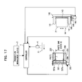
- a fifth embodiment of the present invention will be described in reference to Figs. 17, 18, and 19.
- This embodiment in addition to the position adjustment control of the paste dams described in the fourth embodiment, is characterized in that control for the travel position adjustment of a core is also performed at the same time.
- Fig. 17 is a simplified schematic diagram showing a corrugator with a paster constructed according to this embodiment.
- the core mill roll stand 14 is equipped with a pair of arms 141 and 141, by which the opposite ends of the core roll 211 are rotatably supported.
- the arms 141, 141 are slidablly attached in the direction of the width of the machine to a shaft 142 secured on a floor.
- the arms 141, 141 are engaged by a ball screw 143 extending in the machine width direction, the rear end of which is formed integrally with the rod of a hydraulic cylinder 146.
- the position of the hydraulic cylinder 146 is fixed with respect to the floor.
- the core roll 211 can be moved in the machine width direction integrally with the ball screw 143 and arms 141, 141.
- the ball screw 143 is also connected with a motor 144 through a gear 145. If the ball screw 143 is rotated by the motor 144, the core roll 211 can also be moved in the machine width direction along with the arms 141, 141.
- the controller 1 adjusts the travel position of the core 21 by causing the CCD camera 4 to function as center-position detection means for detecting the center position of the core 21, also causing the aforementioned hydraulic cylinder 146 to function as displacement means for changing the travel position of the core 21, and controlling the hydraulic cylinder 146 based on the image picked up by the CCD camera 4 and moving the core roll 211 in the machine width direction.
- the position adj ustment control of the core 21 by the controller 1 will hereinafter be described in reference to an explanatory diagram of Fig. 19 according to a flowchart shown in Fig. 18.
- the controller 1 then calculates the absolute value of a difference between the calculated center position m0 and a reference position (machine center position), and decides whether the value is within a target value (allowable value) (step T30). If the difference is within the target value, the controller 1 returns to step T10 again. If the difference exceeds the target value, the controller 1 calculates a deviation from the target value (step T40). The controller 1 controls the hydraulic cylinder 146 in dependence on the calculated deviation, moves the core roll 211 in the machine width direction, and adj usts the travel position of the core 21 in a direction where the aforementioned deviation becomes zero (step T50).
- the controller 1 After the center position of the core 21 is aligned with the reference position by the aforementioned control, the controller 1 performs position adjustment control of the paste dams 205, 206 in the control method described in the fourth embodiment.
- the paste dams 205, 206 are symmetrically moved in the machine width direction by the common screw shaft 207 and motor 208. Therefore, when the left and right edges of the core 21 are not at symmetrical positions with respect to the reference position (machine center position), the paste dams 205, 206 cannot be accurately aligned with the paper edges of the core 21.
- position adjustment of the paste dams 205, 206 is performed after the travel position of the core 21 is corrected, so the paste dams 205, 206 can be accurately aligned with the paper edges of the core 21.
- a sixth embodiment of the present invention will be described in reference to Figs. 20, 21, and 22.
- This embodiment is characterized in that in addition to the position adjustment control of the paste dams described in the fourth embodiment and the travel position adjustment control of the core described in the fifth embodiment, control for travel position adjustment of a liner is also performed at the same time.
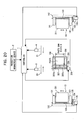
- Fig. 20 is a simplified schematic diagram showing a paster constructed according to this embodiment.
- the construction of a liner mill roll stand 13 is the same as that of a core mill roll stand 14.
- the opposite ends of a liner roll 201 are rotatably supported by arms 131, 131.
- the arms 131, 131 are slidablly attached in the machine width direction to a shaft 132 secured on a floor.
- the arms 131, 131 are engaged by a ball screw 133 extending in the machine width direction, the rear end of which is formed integrally with the rod of a hydraulic cylinder 136. If the hydraulic cylinder 136 is actuated, the core roll 201 can be moved in the machine width direction.
- the ball screw 133 is also connected with a motor 134 through a gear 135. If the ball screw 133 is rotated by the motor 134, the core roll 201 can also be moved in the machine width direction.
- a CCD camera 3 is arranged above the path of travel of a liner 20. Considering thermal contraction of the liner 20 due to heating at a liner preheating roll 117 shown in Fig. 12, it is preferable that the camera 3 be arranged above the liner preheating roll 117 or on the downstream side of the liner preheating roll 117. However, in the case where a distance from the liner preheating roll 117 to a belt roll 111 is short and it is fairly difficult to arrange the CCD camera 3, it may be arranged on the upstream side of the liner preheating roll 117. However, because the liner 20 is also caused to contract by heating at a liner pre-heater 10, it is preferable to arrange the CCD camera 3 on a downstream side from the preheater 10.
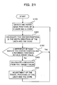
- Fig. 21 is a flowchart showing the function of the controller 1.
- the position adjustment control of the liner 20 and core 21 by the controller 1 will hereinafter be described in reference to an explanatory diagram of Fig. 22 according to the flowchart shown in Fig. 21.
- the controller 1 first detects both paper edges L1 and L2 of the liner 20 from the image picked up by the CCD camera 3, and also detects both paper edges M1 and M2 of the core 21 from the image picked up by the CCD camera 4 (step U10).
- the controller 1 then corrects image distortion employing a correction curve or correction function, and calculates distances 11, 12, m1, and m2 between an imaginary reference line and the paper edges L1, L2, M1 and M2, as shown in Fig. 22, from the positions of the paper edges L1, L2 of the liner 20 within the visual field of the camera 3 and the positions of the paper edges M1, L2 of the liner 20 within the visual field of the camera 4.
- the controller 1 then calculates the absolute values of differences between the calculated center positions 10, m0 and a reference position (machine center position), and decides whether each of the values is within a target value (allowable value) (step U30). If each difference is within the target value, the controller 1 returns to step U10 again. If each difference exceeds the target value, the controller 1 calculates deviations of the core 21 and liner 20 from the target value (step U40). The controller 1 controls the hydraulic cylinder 146 in dependence on the deviation calculated for the core 21, moves the core roll 211 in the machine width direction, and adj usts the travel position of the core 21 in a direction where the deviation becomes zero.
- the controller 1 also controls the hydraulic cylinder 136 in dependence on the deviation calculated for the liner 20, moves the liner roll 201 in the machine width direction, and adjusts the travel position of the liner 20 in a direction where the deviation becomes zero (for the above, step U50).
- the controller 1 After the center position of the liner 20 and the center position of the core 21 are aligned with the reference position by the aforementioned control, the controller 1 performs position adjustment control of the paste dams 205, 206 in the control method described in the fourth embodiment.
- the paste dams 205, 206 can be accurately aligned with the paper edges of the core 21.
- the pasted region of the core 21 can be prevented from protruding from the liner 20 because of misalignment between the center position of the liner 20 and the reference position.
- the alignment method of the liner and the core is not limited to the methods described in the aforementioned embodiments. If one of the two web mediums can be arranged inside the other web medium, other alignment methods are applicable.
- the position detection means for detecting positions in the machine width direction of the liner and core can employ not only image pick-up devices such as CCD cameras, but also displacement sensors.
- both sides of a single faced corrugated sheet may be picked up with two CCD cameras to detect the paper edges of the liner and core.
- the base paper roll of web medium in adjusting the travel position of a web medium, is moved in the machine width direction.
- the base paper roll may be rotated in a plane parallel to the axis to vary the angle between the sending-out direction of the web medium from the base paper roll and the line traveling direction. If the base paper roll is thus rotated, the travel position of the web medium is gradually varied in the machine width direction in dependence on the angle between the sending-out direction of the web medium and the line traveling direction. Therefore, the travel position of the web medium can be adjusted by controlling the angle of rotation of the base paper roll.
- the left and right paste dams are driven by a common screw shaft and a motor, but they may be independently driven by dedicated drive units. In this case, even when the center position of a core is shifted from the machine center position that is a reference position, the paste dams can be accurately aligned with the paper edges of the core by independently adjusting the positions of the paste dams.
Landscapes
- Engineering & Computer Science (AREA)
- Mechanical Engineering (AREA)
- Machines For Manufacturing Corrugated Board In Mechanical Paper-Making Processes (AREA)
Abstract
The present invention relates to a web-position adjustment apparatus used in a single facer. Position detection means (3, 4) detect the positions in a machine width direction of two web mediums (20, 21). Based on the result of detection, control means (1) automatically controls displacement means (136, 146) for changing a travel position of at least one of the two web mediums (20, 21), in such a way that one web medium (21) of the two web mediums is arranged inside the other web medium (20).
The present invention also relates to a paster for a single facer. Paper-edge position detection means (4) detects a position of a paper edge of a core (21) at a position that is above a heating roll (118) arranged very near to a pasting roll (202) or above a downstream side from the heating roll (118). In control means (1) that controls movement means (208) for moving paste dams (205, 206) in the machine width direction, a deviation between the paper edge position detected by paper-edge position detection means (4) and the position of the paste dam detected by paste-dam position detection means (209) is calculated, and the movement means (208) is controlled in a direction where the deviation becomes zero.
Description
- The present invention relates to single facers, and more particularly to alignment techniques of web mediums (a liner and a core) that are to be stuck together in a single facer and to alignment techniques of the paste dams of a paster.
- In single facers, a single faced corrugated sheet is made by corrugating a core that is one of two web mediums, then pasting the ridges of the corrugated core, and sticking a liner that is the other web medium on the pasted surface of the core. In conventional single facers, the position of sticking a core and a liner together is manually adjusted by an operator. The operator checks the pasted state of the core and the liner. When a paper edge of the liner is out of alignment with a paper edge of the core, they are aligned with each other by moving in the width direction at least either a mill roll stand supporting a roll of core or a mill roll stand supporting a roll of liner.
- However, there is an error between the actual width of each web medium and the width displayed on the base paper roll, and because the web mediums are preheated before they are stuck together, contraction will occur in the width direction. For that reason, it is difficult to perfectly prevent misalignment of the core and the liner by the alignment of the base paper rolls relied on operator's perception and know-how. Therefore, in conventional single facers, there is a high possibility that misalignment will occur to some degree between the positions of sticking the core and the liner together. When there is misalignment of the positions of sticking the core and the liner together, particularly when a paper edge of the core protrudes from a paper edge of the liner, the following disadvantages will arise.
- A core and a liner are stuck together with paste, and a single facer is equipped with a paster as a device for supplying paste. The paster is normally equipped with a paste reservoir for storing paste, a pasting roll for causing paste to adhere to the ridges of a corrugated core, and two paste dams. Part of the outer periphery of the pasting roll is immersed in the paste stored within the paste reservoir, and the width of paste adhering to the pasting roll is regulated by damming the paste within the paste reservoir in the machine width direction with the two paste dams.
- The paste dams can be moved in the machine width direction, and the width of paste adhering to the pasting roll can be varied by changing the positions of the paste dams.
- In typical single facers, pasting is performed over the entire region in the width direction of the ridges of a corrugated core. For this reason, when a paper edge of the core is shifted outside a paper edge of the liner, the pasted region of the core will protrude from the surfaces stuck together. The protruding paste will adhere to a core roll, a pressure roll, a pressure belt, etc. , installed around the pasting section of a signal facer, and stains and balls of paste will occur. These stains and paste balls cause a defect in the corrugated surface of a core and machine trouble. A protruding region of each web medium from the surfaces stuck together is a waste region that cannot be utilized as corrugated cardboard. If such a protruding region is increased, waste of paper consumption will be caused. Also, if a protruding region of the core from the surfaces stuck together is increased, waste of paste consumption will be caused.
- To solve such disadvantages, a technique disclosed in
Japanese Laid-Open Patent Publication No. Sho 62-55125 - As set forth in
Japanese Laid-Open Patent Publication No. Hei 8-258187 Japanese Laid-Open Patent Publication No. Hei 7-100976 - However, the technique disclosed in the
Patent Document 1 can prevent the pasted surface of a core from protruding from the surfaces stuck together, but cannot adjust the misalignment in the width direction between two web mediums. For this reason, when there is a great misalignment between web mediums, a protruding region of each web medium from the surfaces stuck together will become great and therefore waste of paper consumption will become great. - In the techniques disclosed in the
Patent Document 2 and Patent Document 3, the position of a paper edge of a core is detected at the upstream side of a heating roll (pre-heater). For this reason, the core is heated and rises in temperature as it passes over the heating roll. At this time, the paper width of the core thermally contracts due to the heat from the heating roll. For this reason, misalignment of the paper edge positions of the core will occur before and after the heating roll. Therefore, even if the position of a paste dam is adjusted so as to align with the position of a paper edge of the core detected before passing the heating roll, as in the techniques disclosed in thePatent Document 2 and Patent Document 3, the position of the paste dam cannot be accurately aligned with the paper edge position of the core. For that reason, waste of paper consumption and paste consumption will become great. - The present invention has been made in view of the aforementioned problems. Accordingly, it is the object of the present invention to provide a web-position adjustment apparatus and paster in a single facer that are capable of reducing waste of paper consumption and paste consumption.
- The present invention has the following means in order to solve the aforementioned problems.
- That is, a web-position adjustment apparatus of the present invention is equipped with displacement means for changing a travel position of at least one of the two web mediums. Position detection means detects the positions in a machine width direction of the two web mediums. Based on the result of detection, control means is constructed to automatically control the displacement means so that one of the two web mediums is arranged inside the other web medium.
- If the travel positions of the web mediums are automatically adjusted so that one of the two web mediums is arranged inside the other web medium, a protruding region of each web medium from the surfaces stuck together can be minimized and therefore waste of paper consumption can be minimized. In addition, even when the paper width of the core is greater than that of the liner, the pasted region of the core that protrudes from the surfaces stuck together can be minimized and therefore waste of paste consumption can be minimized. The occurrence of stains and inferior goods due to extra adhesion of paste can also be prevented.
- The aforementioned position detection means preferably employs an image pick-up device such as a charge-coupled device (CCD) camera, etc. Each web medium is photographed with an image pick-up device arranged above the path of travel of each web medium, and the position in the machine width direction of each web medium is detected by processing the photographed image by image processing means. In the case of an image pick-up device whose angle of field is wide, image distortion will occur at the edge portion of the visual field. Therefore, it is preferable that the image process means have a function of correcting the distortion of an image photographed with an image pick-up device.
- The position detection means preferably detects the positions of the two web mediums, at positions that are above heating rolls arranged very near to a location where the two web mediums are stuck together, or above downstream sides from the heating rolls. Because the paper width of a web medium contracts due to the heat from the heating roll, the position in the machine width direction of the web medium changes before and after the heating roll. Therefore, if position detection is performed at a position that is above the heating roll arranged very near to a location where the two web mediums are stuck together, or above a downstream side from the heating roll, it becomes possible to accurately detect the position in the machine width direction of each web medium at the time of alignment. It is more preferably to detect the position of a web medium above the heating roll. Since the flapping of a web medium can be prevented on the heating roll, more accurate detection becomes possible.
- The aforementioned displacement means may be means for moving a base paper roll of web medium in the machine width direction or may be means for rotating the base paper roll in a plane parallel to the axis of the web roll. If the position in the machine width direction of the base paper roll is changed, the travel position of the web medium also slides in the moving direction of thebasepaperroll. Also, if the base paper roll is rotated to form an angle between the sending-out direction of the web medium from the base paper roll and the line traveling direction, the travel position of the web medium is gradually varied in the machine width direction.
- It is also preferable to perform feedforward control before the start of operation in addition to the aforementioned feedback control after the start of operation. The travel position of each web medium is preset by previously acquiring data about the position in the machine width direction of each web medium (e.g., data about paper width, data about expansion and contraction ratios relative to moisture and temperature, etc.), and controlling the displacement means in dependence on the acquired data by the control means so that one of two web mediums is arranged inside the other web medium. In this manner, it becomes possible to early adjust the travel position of each web medium to a proper travel position in the feedback control after the start of operation, and waste of paper consumption and paste consumption can be reduced.
- Only the aforementioned feedforward control can be performed without performing feedback control. In a small quantity of production, there are cases where there is not sufficient time to perform feedback control. Even in such a case, waste of paper consumption and paste consumption can be reduced by performing the aforementioned feedforward control.
- In a paster of a single facer of the present invention, paper-edge position detection means detects the position of a paper edge of a core at a position that is above a heating roll arranged very near to a pasting roll or above a downstream side from the heating roll. In control means that controls movement means for moving paste dams in the machine width direction, a deviation between the paper edge position detected by paper-edge position detection means and the position of the paste dam detected by paste-dam position detection means is calculated, and the movement means is controlled in a direction where the deviation becomes zero.
- Because the paper width of a core contracts due to the heat from the heating roll, the position in the machine width direction of the core changes before and after the heating roll. Therefore, if the position of a paper edge of the core is detected at a position that is above the heating roll arranged very near to a pasting roll, or above a downstream side from the heating roll, the paper edge position of the core can be accurately detected when the core is pasted. In this manner, the position of the paste dam can be accurately adjusted so as to align with the paper edge position of the core, and the occurrence of stains and inferior goods due to extra paste protruding from the core can be prevented. In addition, waste of paper consumption and paste consumption can be reduced. It is more preferably to detect the paper edge position of the core above the heating roll. Since the flapping of the core can be prevented on the heating roll, more accurate detection of the paper edge position of the core becomes possible.
- The paper-edge position detection means preferably employs an image pick-up device such as a CCD camera, etc. A core is photographed with an image pick-up device arranged above the path of travel of the core, and the position in the machine width direction of the core is detected by processing the photographed image by image processing means. In the case of an image pick-up device whose angle of field is wide, image distortion will occur at the edge portion of the visual field. Therefore, it is preferable that the image process means have a function of correcting the distortion of an image photographed with an image pick-up device.
- It is also preferable to perform feedforward control before the start of operation in addition to the aforementioned feedback control after the start of operation. The position of the paste dam is preset by previously acquiring data about the position in the machine width direction of the core (e. g. , data about paper width, data about expansion and contraction ratios relative to moisture and temperature, etc.), and controlling the movement means in dependence on the acquired data by the control means. In this manner, it becomes possible to early adjust the position of the paste dam to a proper travel position in the feedback control after the start of operation, and waste of paper consumption and paste consumption can be reduced.
- Instead of moving the paste dams at a constant speed from the start of movement to the stop, the control means preferably controls the movement means so that the paste dams are accelerated in a high acceleration rate at the start of movement and are decelerated and stopped in a low deceleration rate at the stop of movement. For instance, in the case where a motor is used as a drive source for the movement means, the variable speed control can be easily realized by applying inverter control. If the variable speed control is thus performed, the paste dams can be moved to desired positions with a high degree of accuracy.
- There are cases where the travel position of the core is shifted in the machine width direction. In such a case, the position of a paste dam may be adjusted so as to align with the shifted position of the core. Preferably, after the position of the core is aligned with a reference position, the position of a dam is adjusted. In adjusting the position of the core, center-position detection means first detects the center position in the width direction of the core at a position that is above the heating roll arranged very near to the pasting roll or above a downstream side from the heating roll. In the control means, a deviation between the center position detected by the center-position detection means and the reference position is calculated, and displacement means for changing the travel position of the core is controlled in a direction where the deviation becomes zero.
-
- FIG. 1(a) is a schematic diagram showing the single facer and vicinity of a corrugator to which a web-position adjustment apparatus according to a first embodiment of the present invention is applied, and is a side view of the entirety;
- FIG. 1(b) is a schematic diagram showing the single facer and vicinity of the corrugator to which the web-position adjustment apparatus according to the first embodiment of the present invention is applied, and is a plan view of the liner mill roll stand;
- FIG. 1(c) is a schematic diagram showing the single facer and vicinity of the corrugator to which the web-position adjustment apparatus according to the first embodiment of the present invention is applied, and is a plan view of the core mill roll stand;
- FIG. 2 is a flowchart showing how position adjustment control of a liner and a core according to the first embodiment of the present invention is performed;
- FIG. 3(a) is an explanatory diagram for explaining the position adjustment control of the liner and the core performed according to the first embodiment of the present invention;
- FIG. 3(b) is an explanatory diagram for explaining the position adjustment control of the liner and the core performed according to the first embodiment of the present invention;
- FIG. 4 is an explanatory diagram for explaining the position adjustment control of the liner and the core performed according to the first embodiment of the present invention;
- FIG. 5 is a flowchart showing a modification of the position adjustment control of the liner and the core performed according to the first embodiment of the present invention;
- FIG. 6 is a flowchart showing how position adjustment control of the liner and the core according to a second embodiment of the present invention is performed;
- FIG. 7(a) is an explanatory diagram for explaining the position adjustment control of the liner and the core performed according to the second embodiment of the present invention;
- FIG. 7(b) is an explanatory diagram for explaining the position adjustment control of the liner and the core performed according to the second embodiment of the present invention;
- FIG. 8 is an explanatory diagram for explaining the position adjustment control of the liner and the core performed according to the second embodiment of the present invention;
- FIG. 9 is a schematic diagram showing the single facer and vicinity of a corrugator to which a web-position adjustment apparatus according to a third embodiment of the present invention is applied;
- FIG. 10 is a flowchart showing how position adjustment control of the liner and the core according to the third embodiment of the present invention is performed;
- FIG. 11(a) is an explanatory diagram for explaining the position adjustment control of the liner and the core performed according to the third embodiment of the present invention;
- FIG. 11(b) is an explanatory diagram for explaining the position adjustment control of the liner and the core performed according to the third embodiment of the present invention;
- FIG. 11(c) is an explanatory diagram for explaining the position adjustment control of the liner and the core performed according to the third embodiment of the present invention;
- FIG. 11(d) is an explanatory diagram for explaining the position adjustment control of the liner and the core performed according to the third embodiment of the present invention;
- FIG. 12 is a schematic diagram showing the single facer and vicinity of a corrugator equipped with a paster constructed according to a fourth embodiment of the present invention is applied, and is a side view of the entirety and a plan view of the entire paster;
- FIG. 13 is a flowchart showing how position adjustment control of paste dams according to the fourth embodiment of the present invention is performed;
- FIG. 14 is an explanatory diagram for explaining the position adjustment control of the paste dams performed according to the fourth embodiment of the present invention;
- FIG. 15 is an explanatory diagram for explaining the position adjustment control of the paste dams performed according to the fourth embodiment of the present invention;
- FIG. 16 is an explanatory diagram for explaining the position adjustment control of the paste dams performed according to the fourth embodiment of the present invention;
- FIG. 17 is a simplified schematic diagram showing a corrugator equipped with a paster constructed according to a fifth embodiment of the present invention;
- FIG. 18 is a flowchart showing how position adjustment control of a core according to the fifth embodiment of the present invention is performed;
- FIG. 19 is an explanatory diagram for explaining position adjustment control of the paste dams performed according to the fifth embodiment of the present invention;
- FIG. 20 is a simplified schematic diagram showing a corrugator equipped with a paster constructed according to a sixth embodiment of the present invention;
- FIG. 21 is a flowchart showing how position adjustment control of the liner and the core according to the sixth embodiment of the present invention is performed; and
- FIG. 22 is an explanatory diagram for explaining the position adjustment control of the liner and the core performed according to the sixth embodiment of the present invention.
- Embodiments of the present invention will hereinafter be described in reference to the drawings.
- Fig. 1(a) is a schematic diagram showing the single facer and vicinity of a corrugator to which a web-position adjustment apparatus according to a first embodiment of the present invention is applied.
- As shown in the figure, a
liner 20 that is one of two web mediums to be stuck together at asingle facer 11 is supported in the form of a roll (hereinafter referred to as a liner roll) 201 by a liner mill roll stand 13. A core 21 that is the other web medium is supported in the form of a roll (hereinafter referred to as a core roll) 211 by a core mill roll stand 14. - As shown in Fig. 1 (b) , the liner mill roll stand 13 is equipped with a pair of
arms liner roll 201 are rotatably supported. Thearms shaft 132 secured on a floor. Thearms ball screw 133 extending in the machine width direction, the rear end of which is formed integrally with the rod of ahydraulic cylinder 136. The position of thehydraulic cylinder 136 is fixed with respect to the floor. If thehydraulic cylinder 136 is actuated, theliner roll 201 can be moved in the machine width direction integrally with theball screw 133 andarms ball screw 133 is also connected with amotor 134 through agear 135. If theball screw 133 is rotated by themotor 134, theliner roll 201 can also be moved in the machine width direction along with thearms - The construction of the core mill roll stand 14 is the same as that of the liner mill roll stand 13. As shown in Fig. 1(c), the opposite ends of the
core roll 211 are rotatably supported byarms arms shaft 142 secured on the floor. Thearms ball screw 143 extending in the machine width direction, the rear end of which is formed integrally with the rod of ahydraulic cylinder 146. If thehydraulic cylinder 146 is actuated, thecore roll 211 can be moved in the machine width direction. Theball screw 143 is also connected with amotor 144 through agear 145. If theball screw 143 is rotated by themotor 144, thecore roll 211 can also be moved in the machine width direction. - The
liner 20 is supplied from the aforementioned liner mill roll stand 13 through aliner pre-heater 10 and to thesingle facer 11. Also, thecore 21 is supplied from the aforementioned core mill roll stand 14 through acore pre-heater 12 and to thesingle facer 11. - The
liner pre-heater 10 is equipped with liner heating rolls 101A, 101B disposed in two stages vertically. The liner heating rolls 101A, 101B are heated to a predetermined temperature by supplying steam to the interiors. Theliner 20, guided in order by guide rolls 105, 104A, 106, and 104B, is wound around the peripheral surfaces of the liner heating rolls 101A, 101B and is preheated by the liner heating rolls 101A, 101B. Thecore pre-heater 12 has the same construction as theliner pre-heater 10 and is equipped with acore heating roll 121 heated to a predetermined temperature by supplying steam to the interior. The core 21 guided by aguide roll 124 is wound around the peripheral surface of thecore heating roll 121 and is preheated by thecore heating roll 121. - The
single facer 11 is equipped with apressure belt 113 looped between abelt roll 111 and atension roll 112; anupper roll 114 with a corrugated surface pressed against thepressure belt 113; and alower roll 115 with a corrugated surface meshing with the corrugated surface of theupper roll 114. Theback liner 20 heated by theliner pre-heater 10 is wound around theliner preheating roll 117 and is preheated. Then, theback liner 20 is guided by thebet roll 111 and is conveyed between the nipping portions of thepressure belt 113 andupper roll 114 along with thepressure belt 113. On the other hand, thecore 21 heated by thecore pre-heater 12 is wound around thecore pre-heating roll 118 and is preheated. Then, thecore 21 is corrugated by the meshing portions of theupper roll 114 andlower roll 115. Next, thecore 21 is guided by theupper roll 114 and is conveyed between the nipping portions of thepressure belt 113 andupper roll 114. - A
paster 116 is arranged near theupper roll 114 and comprises apaste reservoir 116a, apasting roll 116b for pasting the core 21 conveyed by theupper roll 114, adoctor roll 116c for adjusting the amount of paste 30 applied to the peripheral surface of thepasting roll 116b, and ascraper 116d for removing the paste 30 from thedoctor roll 116c. The core 21 corrugated by the meshing portions of the upper andlower rolls liner 20 by the nipping portions of thepressure belt 113 andupper roll 114. In this manner, there is formed a single facedcorrugated sheet 22. - The web-position adjustment apparatus according to this embodiment comprises the
hydraulic cylinder 136 of the liner mill roll stand 13, thehydraulic cylinder 146 of the core mill roll stand 14, two charge-coupled device (CCD)cameras 3 and 4, and acontroller 1. Thehydraulic cylinder 136 functions as displacement means for moving thebase paper roll 201 in the machine width direction to change the travel position of theliner 20. Similarly, thehydraulic cylinder 146 functions as displacement means for moving thebase paper roll 211 in the machine width direction to change the travel position of thecore 21. - The
CCD cameras 3, 4 are image pick-up devices for detecting the positions in the machine width direction of theliner 20 andcore 21. TheCCD camera 4 for picking up the image of thecore 21 is arranged above thecore preheating roll 118 within thesingle facer 11. The paper width of the core 21 contracts due to heating at thecore preheating roll 118, so the position in the machine-width direction changes before and after thecore preheating roll 118. However, if theCCD camera 4 is arranged above thecore preheating roll 118 and picks up the image of the core 21 placed on thecore preheating roll 118, the position in the machine width direction of the core 21 can be accurately detected. To exclude the influence of the contraction of thecore 21 due to heating, theCCD camera 4 may be arranged on a downstream side from thecore preheating roll 118. However, in the case where the image of thecore 21 is picked up above thecore preheating roll 118, there is no flapping of thecore 21 and therefore the position in the machine width direction of the core 21 can be more accurately detected. On the other hand, in the structure shown in Fig. 1(a), space to arrange the CCD camera 3 is limited because a distance from theliner preheating roll 117 to thebelt roll 111 is short, so the CCD camera 3 is arranged above the path of travel between theliner pre-heater 10 and thesingle facer 11. However, when there is no limit to arrangement space, it is preferable to arrange the CCD camera 3 above theliner preheating roll 117 or on a downstream side from theliner preheating roll 117. - The images picked up by the
CCD cameras 3, 4 are transmitted to thecontroller 1. Thecontroller 1 functions as image processing means for processing the images picked up by theCCD cameras 3, 4 and as feedback control means for controlling thehydraulic cylinders controller 1. The position adjustment control of theliner 20 andcore 21 by thecontroller 1 will hereinafter be described in reference to Figs. 3 (a) and 3 (b) and Fig. 4 according to the flowchart shown in Fig. 2. - First, the
controller 1, as shown in Fig. 3 (a) , detects the paper edge L1 on the driving side (back side of Fig. 1(a) where driving systems, such as motors, gears, etc. , are installed) of theliner 20 from the image picked up by the CCD camera 3 and, as shown in Fig. 3 (b) , detects the paper edge M1 on the driving side of the core 21 from the image picked up by theCCD camera 4. Thevisual fields CCD cameras 3, 4 are fixed (for the above, step A10). - Next, from the position of the paper edge L1 of the
liner 20 within the visual filed 3a and the position of the paper edge M1 of thecore 21 within thevisual field 4a, thecontroller 1 calculates adistance 11 between an imaginary reference line and the paper edge L1 and a distance m1 between the imaginary reference line and the paper edge M1, as shown in Fig. 4. Since theCCD cameras 3, 4 have a wide angle of field, distortion will occur in the edge portions of thevisual fields controller 1 corrects image distortion employing a correction curve or correction function and then calculates thedistances 11 and m1 (for the above, step A20). - Next, the
controller 1 calculates the absolute value of the difference between the two distances (m1 - 11) and decides whether or not the calculated value is within a target value (allowable value) δ (preferably, 0) (step A30). If the difference in distance is within the target value, thecontroller 1 returns to step A10. If the difference in distance exceeds the target value, thecontroller 1 calculates a deviation between the difference in distance and the target value (step A40). Thecontroller 1 controls thehydraulic cylinder liner roll 201 orcore roll 211 in the machine width direction, and adjusts the travel direction of theliner 20 orcore 21 in a direction where the aforementioned deviation becomes zero (step A50). Thehydraulic cylinders hydraulic cylinder 136 may be actuated and if the deviation is negative thehydraulic cylinder 146 may be actuated. That is, the hydraulic cylinder to be actuated may be decided according to the direction of the deviation. - Thus, if the travel position of the
liner 20 orcore 21 is adjusted so the paper edge of theliner 20 is aligned with the paper edge of the core 21, one of the two web mediums is positioned inside the other web medium and therefore a protruding region of theliner 20 orcore 21 from the surfaces stuck together can be minimized. For instance, when the paper width of thecore 21 is greater than that of theliner 20, a pasted region of the core 21 always protrudes from the surfaces stuck together, but if the aforementioned paper edges are aligned with each other, the pasted region of the core 21 protruding from the surfaces stuck together can be minimized. This can reduce waste of paper consumption and waste of paste consumption and can also prevent the occurrence of stains and inferior goods due to extra adhesion of paste. - In the case of a small quantity of production, there are cases where there is no sufficient time to perform the aforementioned feedback control. In such a case, the aforementioned feedback control may be combined with feedforward control, as shown in Fig. 5. In this feedforward control, the
controller 1 first receives data about the positions in the machine width directions of theliner 20 andcore 21 from a production management device 2 (step A01). The data about the positions in the machine width directions includes, for example, the paper widths of theliner 20 andcore 21, expansion and contraction ratios for each paper type relative to moisture and temperature, moisture contents and temperature of web mediums just before they are stuck together, etc. - And the
controller 1 predicts a deviation between the paper edge of theliner 20 and the paper edge of the core 21 from the received data, controls thehydraulic cylinder liner roll 201 orcore roll 211 in the machine width direction, and presets the travel positions of theliner 20 and core 21 (step A02). Note that in the initial state before the start of feedforward control, theliner roll 201 andcore roll 211 are assumed to be set at predetermined initial positions. After the presetting, operation is started to perform the aforementioned feedback control (steps A10 to A50). - Thus, if the travel positions of the
liner 20 andcore 21 are preset before the start of operation, it becomes possible to early adjust the travel positions of theliner 20 andcore 21 to proper positions. In addition, even when there is no sufficient time to perform feedback control because of a small quantity of production, waste of paper consumption and paste consumption can be reduced. - A second embodiment of the present invention will be described with reference to Figs. 6, 7(a), 7(b), and 8. This method differs from the first embodiment in the function of the
controller 1, that is, position adjustment method of two web mediums. The construction other than the function of thecontroller 1 is the same as the first embodiment. The entire construction is represented in Figs. 1(a), 1(b), and 1(c), as with the first embodiment. Position adjustment control of theliner 20 andcore 21 according to this embodiment will be described in reference to Figs. 7(a), 7(b), and 8 according to a flowchart shown in Fig. 6. - First, the
controller 1, as shown in Fig. 7 (a), detects both paper edges L1 and L2 of theliner 20 from the image picked up by the CCD camera 3 and, as shown in Fig. 7(b), detects both paper edges M1 and M2 of the core 21 from the image picked up by the CCD camera 4 (for the above, step B10). - Next, the
controller 1 corrects image distortion employing a correction curve or correction function. Thereafter, from the positions of the paper edges L1 and L2 of theliner 20 within thevisual field 3a and the positions of the paper edges M1 and M2 of thecore 21 within thevisual field 4a, thecontroller 1 respectively calculates thedistance controller 1 calculates the center position 10 [10= (12 + 11)/2] in the width direction of theliner 20 from thedistances - Next, the
controller 1 calculates the absolute value of the difference between the two distances (m0 - 10) and decides whether or not the calculated value is within a target value (allowable value) δ (preferably, 0) (step B30). If the difference in distance is within the target value, thecontroller 1 returns to step B10. If the difference in distance exceeds the target value, thecontroller 1 calculates a deviation between the difference in distance and the target value (step B40). Thecontroller 1 controls thehydraulic cylinder liner roll 201 orcore roll 211 in the machine width direction, and adjusts the travel direction of theliner 20 orcore 21 in a direction where the aforementioned deviation becomes zero (step B50). - Thus, if the travel position of the
liner 20 orcore 21 is adjusted so the center position of theliner 20 is aligned with the center position of the core 21, one of the two web mediums is positioned inside the other web medium, as with the first embodiment. Therefore, a protruding region of theliner 20 orcore 21 from the surfaces stuck together can be minimized. In this embodiment, as with the first embodiment, the travel positions of theliner 20 andcore 21 may be preset before the start of operation by performing feedforward control prior to the aforementioned feedback control. - A third embodiment of the present invention will be described in reference to Figs. 9, 10, 11(a), 11(b), 11(c), and 11(d). A web-position adjustment apparatus according to this embodiment, as shown in Fig. 9, employs a
single CCD camera 5 as an image pick-up device for detecting positions in the machine width direction of aliner 20 and acore 21. TheCCD camera 5 is arranged above the path of travel of a single facedcorrugated sheet 22 manufactured by sticking theliner 20 andcore 21 together. Note in Fig. 9 that the same parts as the first embodiment are given the same reference numbers. - The image picked up by the
CCD camera 5 is transmitted to acontroller 1, in which image processing is performed. Fig. 10 is a flowchart showing the function of thecontroller 1. Position adjustment control of theliner 20 andcore 21 in this embodiment will be described in reference to Figs. 11(a), 11(b), 11(c), and 11(d) according to the flowchart shown in Fig. 10. - First, the
controller 1, as shown in Figs. 11(a), 11(b), 11(c), and 11(d), detects the paper edges L1 and L2 of theliner 20 and the paper edges M1 and M2 of the core 21 from the image picked up by the CCD camera 5 (step C10). The surface of theliner 20 is smooth, while the corrugated surface of thecore 1 has alternate ridges and grooves. Therefore, since theliner 20 and the core 21 distinctly differ in luminance distribution, theliner 20 can be distinctly discriminated from the core 21 by image processing. - As shown Figs. 11 (a), 11 (b), 11 (c), and 11 (d), there are four cases in the positional relationship between the paper edges L1 and L2 of the
liner 20 and the paper edges M1 and M2 of the core 21, detected in step C10. Fig. 11 (a) shows the first case in which the both paper edges M1 and M2 of the core 21 protrude from both paper edges L1 and L2 of theliner 20. Fig. 11(b) shows the second case in which the paper edge M1 of the core 21 protrudes from the paper edge L1 on the driving side of theliner 20. Fig. 11(c) shows the third case in which the paper edge M2 of the core 21 protrudes from the paper edge L2 on the operating side of theliner 20. Fig. 11 (d) shows the fourth case in which thecore 21 is hidden inside the paper edges L1 and L2 of theliner 20. - Next, the
controller 1 decides which of the aforementioned four cases corresponds to the positional relationship between the paper edges L1 and L2 of theliner 20 and the paper edges M1 and M2 of the core 21 (step C20), photographed with theCCD camera 5 and performs control according to the decided case. In the first case shown in Fig. 11(a) theliner 20 is arranged inside thecore 21, and in the fourth case shown in Fig. 11(d) thecore 21 is arranged inside theliner 20. In these cases, a protruding region of theliner 20 orcore 21 from the surfaces stuck together has reached a minimum, so there is no need to adjust the travel positions of theliner 20 andcore 21. Therefore, in these cases, thecontroller 1 returns to step C10. - On the other hand, in the first case shown in Fig. 11(b), there is a possibility that the paper edge M2 of the core 21 will be arranged inside the paper edge L2 of the
liner 20. Therefore, in this case, the controller controls thehydraulic cylinder liner 20 and the paper edge M1 of the core 21 are aligned with each other, and moves theliner roll 201 orcore roll 211 in the machine width direction to adjust the travel position of theliner 20 orcore 21. Also, in the third case shown in Fig. 11 (c), there is a possibility that the paper edge M1 of the core 21 will be arranged inside the paper edge L1 of theliner 20. In this case, thecontroller 1 moves theliner roll 201 orcore roll 211 in the machine width direction so that the paper edge L2 of theliner 20 and the paper edge M2 of the core 21 are aligned with each other, and adjusts the travel position of theliner 20 orcore 21. The aforementioned processing steps may be performed in the same manner as the steps A20 to A50 described in the first embodiment (for the above, step C30). - According to the web-position adjustment apparatus according to this embodiment, the
single CCD camera 5 is used, so costs can be reduced compared with the first and second embodiments. In addition, whether to adjust the travel position of theliner 20 orcore 21 is decided from the positional relationship between theliner 20 and the core 21 actually stuck together, so more accurate adjustments become possible. In this embodiment, as with the first and second embodiments, the travel positions of theliner 20 andcore 21 may be preset before the start of operation by performing feedforward control prior to the aforementioned feedback control. - Fig. 12 is a schematic diagram showing the single facer and vicinity of a corrugator equipped with a paster constructed according to a fourth embodiment of the present invention.
- As shown in the figure, a
liner 20 that is one of two web mediums to be stuck together at asingle facer 11 is supported in the form of a roll (hereinafter referred to as a liner roll) 201 by a liner mill roll stand 13. A core 21 that is the other web medium is supported in the form of a roll (hereinafter referred to as a core roll) 211 by a core mill roll stand 14. Theliner 20 is supplied from the liner mill roll stand 13 through aliner pre-heater 10 and to thesingle facer 11. Also, thecore 21 is supplied from the core mill roll stand 14 through acore pre-heater 12 and to thesingle facer 11. - The
liner pre-heater 10 is equipped with liner heating rolls 101A, 101B disposed in two stages vertically. The liner heating rolls 101A, 101B are heated to a predetermined temperature by supplying steam to the interiors. Theliner 20, guided in order by guide rolls 105, 104A, 106, and 104B, is wound around the peripheral surfaces of the liner heating rolls 101A, 101B and is preheated by the liner heating rolls 101A, 101B. Thecore pre-heater 12 has the same construction as theliner pre-heater 10 and is equipped with acore heating roll 121 heated to a predetermined temperature by supplying steam to the interior. The core 21 guided by aguide roll 124 is wound around the peripheral surface of thecore heating roll 121 and is preheated by thecore heating roll 121. - The
single facer 11 is equipped with apressure belt 113 looped between abelt roll 111 and atension roll 112; anupper roll 114 with a corrugated surface pressed against thepressure belt 113; and alower roll 115 with a corrugated surface meshing with the corrugated surface of theupper roll 114. Theback liner 20 heated by theliner pre-heater 10 is wound around theliner preheating roll 117 and is preheated. Then, theback liner 20 is guided by thebet roll 111 and is conveyed between the nipping portions of thepressure belt 113 andupper roll 114 along with thepressure belt 113. On the other hand, thecore 21 heated by thecore pre-heater 12 is wound around thecore pre-heating roll 118 and is preheated. Then, thecore 21 is corrugated by the meshing portions of theupper roll 114 andlower roll 115. Next, thecore 21 is guided by theupper roll 114 and is conveyed between the nipping portions of thepressure belt 113 andupper roll 114. -
Apastermain body 200 is arranged in the vicinity of theupper roll 114 and comprises apaste reservoir 201 and apasting roll 202. The outer peripheral surface of thepasting roll 202 contacts the ridges of the corrugated surface of the core 21 conveyed by theupper roll 114, and part of the outer peripheral surface is immersed in the paste stored within thepaste reservoir 201. The paste within the paste reservoir is taken out from thepaste reservoir 201 by rotation of thepasting roll 202, and the paste adhering to the outer peripheral surface of thepasting roll 202 is supplied to the ridges of the corrugated surface of thecore 21. The amount of paste on the outer peripheral surface of thepasting roll 202 is adjusted by adoctor roll 203. The paste transferred from thepasting roll 202 onto thedoctor roll 203 is removed from the surface of thedoctor roll 203 by ascraper 204. The core 21 pasted at the ridges of the corrugated surface by thepasting roll 202 is stuck on theliner 20 by the nipping portions of thepressure belt 113 andupper roll 114. In this way, there is formed a single facedcorrugated sheet 22. - The paster
main body 200, as shown in Fig. 12, is provided withpaste dams paste reservoir 201. The width of the paste on thepasting roll 202 is determined by the positions of the left andright paste dams paste dams pasting roll 202 and consequently to the pasted width on thecore 21. Thepaste dams common screw shaft 207. Thescrew shaft 207 is provided parallel to thepasting roll 202 and has an end portion connected with amotor 208. Thescrew shaft 207 has two axially spacedregions paste dam 205 is attached to one screwedregion 207a, and theother paste dam 206 is attached to the other screwedregion 207b. Therefore, the left andright paste dams motor 208. If themotor 208 is positively rotated, thepaste dams paste dams motor 208 is reversely rotated, thepaste dams paste dams - The positions in the machine width direction of the
paste dams screw shaft 207, that is, the number of revolutions of themotor 208. To measure the number of revolutions, themotor 208 has anencoder 209 attached thereto. Theencoder 209 functions as paste-dam position detection means for detecting positions in the machine width direction of thepaste dams - The paster according to this embodiment comprises the aforementioned paster
main body 200, aCCD camera 4, and acontroller 1. TheCCD camera 4 is an image pick-up device for detecting a position in the machine width direction of thecore 21 and is arranged above thecore preheating roll 118 that is a heating roll within thesingle facer 11. Since the paper width of thecore 21 is contracted by heating at thecore preheating roll 118, the position in the machine width direction changes before and after thecore preheating roll 118. However, if theCCD camera 4 is arranged above thecore preheating roll 118 and picks up the image of the core 21 wound around the preheatingroll 118, the position in the machine width direction of the core 21 can be accurately detected. Also, theCCD camera 4 may be arranged on a downstream side from thecore preheating roll 118 in order to exclude the influence of the contraction of thecore 21 due to heating. However, in the case where the image of thecore 21 is picked up above thecore preheating roll 118, there is no flapping of thecore 21 and therefore the position in the machine width direction of the core 21 can be more accurately detected. - A signal from the
encoder 209 and an image picked up by theCCD camera 4 are transmitted to thecontroller 1. Thecontroller 1 functions as image processing means for processing the image picked up by theCCD camera 4 and as control means for controlling rotation of themotor 208 based on the result of image processing and the signal from theencoder 209. Fig. 13 is a flowchart showing these functions of thecontroller 1. The position adjustment control of thepaste dams controller 1 will hereinafter be described in reference to Figs. 14, 15, and 16 according to the flowchart shown in Fig. 13. - The
controller 1 first receives data about the position in the machine width direction of the core 21 from a production management device 2 (step S10). The data about the position in the machine width direction includes, for example, the paper width of the core 21, expansion and contraction ratios for each paper type relative to moisture and temperature, moisture contents and temperature of the core 21 just before it is pasted, etc. - Next, the
controller 1 sets acceleration and deceleration rates and steady moving speed for moving thepaste dams 205, 206 (step S20). The control of themotor 208 by thecontroller 1 is variable speed control by an inverter. Thepaste dams motor 208 in a speed pattern such as that shown in Fig. 16. More specifically, at the start of movement, thepaste dams paste dams paste dams - Next, the
controller 1 calculates a moving width for thepaste dams paste dams motor 208 according to the set values of the acceleration and deceleration rates and constant speed, and thepaste dams paste dams paste dams - In feedback control, the
controller 1 detects the paper edges M1 and M2 on the driving and operating sides of the core 21 from the image picked up by theCCD camera 4, as shown in Fig. 14. Note that thevisual field 4a of theCCD camera 4 is fixed (for the above, step S40) . - Next, the
controller 1 calculates a distance m1 between an imaginary reference line and the paper edge M1 and a distance m2 between the imaginary reference line and the paper edge M2, as shown in Fig. 15, from the positions of the paper edges M1 and M2 of thecore 21 within thevisual field 4a. Since theCCD camera 4 has a wide angle of field, distortion will occur in the edge portion of thevisual field 4a. Therefore, thecontroller 1 corrects image distortion employing a correction curve or correction function, and then calculates the distances m1 and m2 (step S50). - The
controller 1 also detects the current positions of thepaste dams motor 208 measured by theencoder 209. And thecontroller 1 calculates a distance d1 between the aforementioned reference line and the current position of thepaste dam 205 and a distance d2 between the reference line and the current position of the paste dam 206 (step S60). - And the
controller 1 calculates an absolute value of a difference (m1 - d1) between the distance m1 of the driving-side paper edge M1 of the core 21 from the reference line and the distance d1 of the driving-side paste dam 205 from the reference line, and an absolute value of a difference (m2 - d2) between the distance m2 of the operating-side paper edge M2 of the core 21 from the reference line and the distance d2 of the operating-side paste dam 206 from the reference line, and decides whether these absolute values are within a target value (allowable value) (step S70). - As the result of decision in step S70, if the difference in distance is within the target value, the
controller 1 returns to step S40 again. If the difference in distance exceeds the target value, thecontroller 1 calculates a deviation between the difference in distance and the target value (step S80). Thecontroller 1 specifically sets the acceleration and deceleration rates during the a-interval, c-interval, and d-interval of the speed pattern shown in Fig. 16 and the constant speed during the b-interval of the speed pattern shown in Fig. 16, from the calculated deviation and the speed pattern set in step S20. And thepaste dams motor 208 according to the set values of the acceleration and deceleration rates and constant speed (step S90). - Thus, by moving the
paste dams core preheating roll 118 near thepasting roll 202, the positions of thepaste dams core 21. In addition, since thepaste dams paste dams core 21, and reducing waste of paper consumption and waste of paste consumption. - A fifth embodiment of the present invention will be described in reference to Figs. 17, 18, and 19. This embodiment, in addition to the position adjustment control of the paste dams described in the fourth embodiment, is characterized in that control for the travel position adjustment of a core is also performed at the same time.
- Fig. 17 is a simplified schematic diagram showing a corrugator with a paster constructed according to this embodiment. As shown in the figure, the core mill roll stand 14 is equipped with a pair of
arms core roll 211 are rotatably supported. Thearms shaft 142 secured on a floor. Thearms ball screw 143 extending in the machine width direction, the rear end of which is formed integrally with the rod of ahydraulic cylinder 146. The position of thehydraulic cylinder 146 is fixed with respect to the floor. If thehydraulic cylinder 146 is actuated, thecore roll 211 can be moved in the machine width direction integrally with theball screw 143 andarms ball screw 143 is also connected with amotor 144 through agear 145. If theball screw 143 is rotated by themotor 144, thecore roll 211 can also be moved in the machine width direction along with thearms - The
controller 1 adjusts the travel position of the core 21 by causing theCCD camera 4 to function as center-position detection means for detecting the center position of the core 21, also causing the aforementionedhydraulic cylinder 146 to function as displacement means for changing the travel position of the core 21, and controlling thehydraulic cylinder 146 based on the image picked up by theCCD camera 4 and moving thecore roll 211 in the machine width direction. The position adj ustment control of the core 21 by thecontroller 1 will hereinafter be described in reference to an explanatory diagram of Fig. 19 according to a flowchart shown in Fig. 18. - The
controller 1 first detects both paper edges M1 and M2 of the core 21 from the image picked up by the CCD camera 4 (step T10). Thecontroller 1 then corrects image distortion employing a correction curve or correction function, and calculates distances m1 and m2 between an imaginary reference line and both paper edges M1 and M2, as shown in Fig. 19, from the positions of the paper edges M1, M2 of thecore 21 within the visual field of thecamera 4. And thecontroller 1 calculates the center position m0 [m0 = (m2 + m1)/2] in the width direction of the core 21 from the distances m1, m2 (for the above, step T20). - The
controller 1 then calculates the absolute value of a difference between the calculated center position m0 and a reference position (machine center position), and decides whether the value is within a target value (allowable value) (step T30). If the difference is within the target value, thecontroller 1 returns to step T10 again. If the difference exceeds the target value, thecontroller 1 calculates a deviation from the target value (step T40). Thecontroller 1 controls thehydraulic cylinder 146 in dependence on the calculated deviation, moves thecore roll 211 in the machine width direction, and adj usts the travel position of the core 21 in a direction where the aforementioned deviation becomes zero (step T50). - After the center position of the
core 21 is aligned with the reference position by the aforementioned control, thecontroller 1 performs position adjustment control of thepaste dams paste dams common screw shaft 207 andmotor 208. Therefore, when the left and right edges of the core 21 are not at symmetrical positions with respect to the reference position (machine center position), thepaste dams core 21. In contract with this, according to the paster of this embodiment, position adjustment of thepaste dams core 21 is corrected, so thepaste dams core 21. - A sixth embodiment of the present invention will be described in reference to Figs. 20, 21, and 22. This embodiment is characterized in that in addition to the position adjustment control of the paste dams described in the fourth embodiment and the travel position adjustment control of the core described in the fifth embodiment, control for travel position adjustment of a liner is also performed at the same time.
- Fig. 20 is a simplified schematic diagram showing a paster constructed according to this embodiment. As shown in the figure, the construction of a liner mill roll stand 13 is the same as that of a core mill roll stand 14. The opposite ends of a
liner roll 201 are rotatably supported byarms arms shaft 132 secured on a floor. Thearms ball screw 133 extending in the machine width direction, the rear end of which is formed integrally with the rod of ahydraulic cylinder 136. If thehydraulic cylinder 136 is actuated, thecore roll 201 can be moved in the machine width direction. Theball screw 133 is also connected with amotor 134 through agear 135. If theball screw 133 is rotated by themotor 134, thecore roll 201 can also be moved in the machine width direction. - A CCD camera 3 is arranged above the path of travel of a
liner 20. Considering thermal contraction of theliner 20 due to heating at aliner preheating roll 117 shown in Fig. 12, it is preferable that the camera 3 be arranged above theliner preheating roll 117 or on the downstream side of theliner preheating roll 117. However, in the case where a distance from theliner preheating roll 117 to abelt roll 111 is short and it is fairly difficult to arrange the CCD camera 3, it may be arranged on the upstream side of theliner preheating roll 117. However, because theliner 20 is also caused to contract by heating at aliner pre-heater 10, it is preferable to arrange the CCD camera 3 on a downstream side from thepreheater 10. - The image picked up by a
CCD camera 4, along with the image picked up by the CCD camera 3, is transmitted to acontroller 1, in which they are processed. Fig. 21 is a flowchart showing the function of thecontroller 1. The position adjustment control of theliner 20 andcore 21 by thecontroller 1 will hereinafter be described in reference to an explanatory diagram of Fig. 22 according to the flowchart shown in Fig. 21. - The
controller 1 first detects both paper edges L1 and L2 of theliner 20 from the image picked up by the CCD camera 3, and also detects both paper edges M1 and M2 of the core 21 from the image picked up by the CCD camera 4 (step U10). Thecontroller 1 then corrects image distortion employing a correction curve or correction function, and calculatesdistances liner 20 within the visual field of the camera 3 and the positions of the paper edges M1, L2 of theliner 20 within the visual field of thecamera 4. And thecontroller 1 calculates the center position 10 [10 = (12 + 11)/2] in the width direction of theliner 20 from thedistances - The
controller 1 then calculates the absolute values of differences between the calculated center positions 10, m0 and a reference position (machine center position), and decides whether each of the values is within a target value (allowable value) (step U30). If each difference is within the target value, thecontroller 1 returns to step U10 again. If each difference exceeds the target value, thecontroller 1 calculates deviations of thecore 21 andliner 20 from the target value (step U40). Thecontroller 1 controls thehydraulic cylinder 146 in dependence on the deviation calculated for the core 21, moves thecore roll 211 in the machine width direction, and adj usts the travel position of the core 21 in a direction where the deviation becomes zero. Thecontroller 1 also controls thehydraulic cylinder 136 in dependence on the deviation calculated for theliner 20, moves theliner roll 201 in the machine width direction, and adjusts the travel position of theliner 20 in a direction where the deviation becomes zero (for the above, step U50). - After the center position of the
liner 20 and the center position of the core 21 are aligned with the reference position by the aforementioned control, thecontroller 1 performs position adjustment control of thepaste dams paste dams liner 20 andcore 21 are thus corrected, thepaste dams core 21. In addition, the pasted region of the core 21 can be prevented from protruding from theliner 20 because of misalignment between the center position of theliner 20 and the reference position. - While the present invention has been described with reference to the preferred embodiments thereof, the invention is not to be limited to the details given herein, but may be modified within the scope of the invention hereinafter claimed. For example, the alignment method of the liner and the core is not limited to the methods described in the aforementioned embodiments. If one of the two web mediums can be arranged inside the other web medium, other alignment methods are applicable.
- The position detection means for detecting positions in the machine width direction of the liner and core can employ not only image pick-up devices such as CCD cameras, but also displacement sensors.
- In the third embodiment, while only one side of a single faced corrugated sheet is picked up with a single CCD camera, both sides of a single faced corrugated sheet may be picked up with two CCD cameras to detect the paper edges of the liner and core.
- In the embodiments, in adjusting the travel position of a web medium, the base paper roll of web medium is moved in the machine width direction. However, the base paper roll may be rotated in a plane parallel to the axis to vary the angle between the sending-out direction of the web medium from the base paper roll and the line traveling direction. If the base paper roll is thus rotated, the travel position of the web medium is gradually varied in the machine width direction in dependence on the angle between the sending-out direction of the web medium and the line traveling direction. Therefore, the travel position of the web medium can be adjusted by controlling the angle of rotation of the base paper roll.
- In the fourth embodiment, the left and right paste dams are driven by a common screw shaft and a motor, but they may be independently driven by dedicated drive units. In this case, even when the center position of a core is shifted from the machine center position that is a reference position, the paste dams can be accurately aligned with the paper edges of the core by independently adjusting the positions of the paste dams.
Claims (8)
- A position adjustment apparatus comprising:position detection means (3, 4) for detecting positions in a machine width direction of two web mediums (20, 21) that are to be stuck together in a single facer;displacement means (136, 146) for changing a travel position of at least one of said two web mediums (20, 21); andcontrol means (1) for controlling said displacement means (136, 146);wherein said control means (1) is constructed to control said displacement means (136, 146), based on a result of detection obtained by said position detection means (3, 4), so that one (21) of said two web mediums is arranged inside the other web medium (20).
- The position adjustment apparatus as set forth in claim 1, wherein said position detection means (3, 4) are constructed to detect positions of said two web mediums (20, 21), at positions that are above heating rolls (117, 118) arranged very near to a location where said two web mediums (20, 21) are stuck together, or above downstream sides from said heating rolls (117, 118).
- The position adjustment apparatus as set forth in claim 1 or 2, wherein said displacement means (136, 146) comprise means for moving rolls (201, 211) of said web mediums (3, 4) in said machine width direction and/or rotating said rolls in planes parallel to axes of said rolls.
- The position adjustment apparatus as set forth in any one of claims 1 to 3, further comprising:data acquisition means for acquiring data about a position in said machine width direction of each of said web mediums (3, 4);wherein said control means (1) is constructed to preset a travel position of each of said two web medium (20, 21) prior to the start of operation, by controlling said displacement means (136, 146) in dependence on said data so that one (21) of said web mediums is arranged inside the other web medium (20).
- A position adjustment apparatus comprising:data acquisition means for acquiring data about positions in a machine width direction of two web mediums (20, 21) that are to be stuck together in a single facer;displacement means (136, 146) for changing a travel position of at least one of said two web mediums (20, 21); andcontrol means (1) for controlling said displacement means (136, 146);wherein said control means (1) is constructed to preset the travel position of each of said two web medium (20, 21) by controlling said displacement means (136, 146) in dependence on said data so that one (21) of said two web mediums is arranged inside the other web medium (20).
- A paster for a single facer comprising:a pasting roll (202) for causing paste within a paste reservoir (201) to adhere to a core (21);paste dams (205, 206), which constitute side walls of said paste reservoir (201), for regulating a width of said paste adhering to said pasting roll (202);paper-edge position detection means (4) for detecting a position of a paper edge of said core (21) at a position that is above a heating roll (118) arranged very near to said pasting roll (202) or above a downstream side from said heating roll (118);paste-dam position detection means (209) for detecting positions of said paste dams (205, 206);movement means (208) for moving said paste dams (205, 206) in a machine width direction; andcontrol means (1) for controlling said movement means (208);wherein said control means (1) is constructed to calculate a deviation between the paper edge position detected by said paper-edge position detection means (4) and the paste dam position detected by said paste-dam position detection means (209), and control said movement means (208) in a direction where said deviation becomes zero.
- The paster as set forth in claim 6, further comprising:data acquisition means for acquiring data about a position of a paper edge of said core (21);wherein said control means (1) is constructed to preset positions of said paste dams (205, 206) by controlling said movement means (208) in dependence on said data, prior to the start of operation.
- The paster as set forth in claim 6 or 7, wherein said control means (1) is constructed to control said movement means (208) so that said paste dams (205, 206) are accelerated in a high acceleration rate at the start of movement and are decelerated and stopped in a low deceleration rate at the stop of movement.
Applications Claiming Priority (1)
| Application Number | Priority Date | Filing Date | Title |
|---|---|---|---|
| PCT/JP2004/006140 WO2005105636A1 (en) | 2004-04-28 | 2004-04-28 | Single facer web member position adjusting device, and single facer sizing device |
Publications (2)
| Publication Number | Publication Date |
|---|---|
| EP1757548A1 true EP1757548A1 (en) | 2007-02-28 |
| EP1757548A4 EP1757548A4 (en) | 2010-04-07 |
Family
ID=35241566
Family Applications (1)
| Application Number | Title | Priority Date | Filing Date |
|---|---|---|---|
| EP04730030A Withdrawn EP1757548A4 (en) | 2004-04-28 | 2004-04-28 | Single facer web member position adjusting device, and single facer sizing device |
Country Status (2)
| Country | Link |
|---|---|
| EP (1) | EP1757548A4 (en) |
| WO (1) | WO2005105636A1 (en) |
Cited By (9)
| Publication number | Priority date | Publication date | Assignee | Title |
|---|---|---|---|---|
| EP2048494A1 (en) * | 2007-10-09 | 2009-04-15 | BHS Corrugated Maschinen-und Anlagenbau GmbH | Device for recording the format fidelity of a corrugated cardboard sheet |
| EP2128059A1 (en) * | 2008-05-28 | 2009-12-02 | Applied Materials, Inc. | Automatic edge guide |
| US8616488B2 (en) | 2008-05-28 | 2013-12-31 | Applied Materials, Inc. | Automatic edge guide |
| US20160052249A1 (en) * | 2014-08-19 | 2016-02-25 | Kabushiki Kaisha Isowa | Gluing device |
| CN111976224A (en) * | 2019-05-23 | 2020-11-24 | Bhs波纹机械和设备制造有限公司 | Assembly |
| WO2022043024A1 (en) * | 2020-08-31 | 2022-03-03 | Fosber S.P.A. | Plant and method for producing a corrugated board |
| WO2022112128A1 (en) | 2020-11-24 | 2022-06-02 | Fosber S.P.A. | Single facer with heating plates for producing corrugated board |
| DE102022104780A1 (en) | 2022-03-01 | 2023-09-07 | Texmag Gmbh Vertriebsgesellschaft | Process for the temporal position control of webs |
| DE102022207584A1 (en) | 2022-07-25 | 2024-01-25 | Bhs Corrugated Maschinen- Und Anlagenbau Gmbh | arrangement |
Family Cites Families (6)
| Publication number | Priority date | Publication date | Assignee | Title |
|---|---|---|---|---|
| JPS591654B2 (en) * | 1980-10-02 | 1984-01-13 | レンゴ−株式会社 | Method and device for adjusting positional deviation of web material in corrugator |
| JPS5812546U (en) * | 1981-07-17 | 1983-01-26 | 株式会社磯輪鉄工所 | Automatic cardboard positioning device |
| JPS6255125A (en) * | 1985-09-04 | 1987-03-10 | レンゴ−株式会社 | Starching siding adjusting method to web material in corrugator |
| JPH08258187A (en) * | 1995-03-27 | 1996-10-08 | Mitsubishi Heavy Ind Ltd | Method and apparatus for sizing in corrugate machine |
| IL119416A0 (en) * | 1996-10-13 | 1997-01-10 | Opsigal Ltd | Web alignment system and method |
| CA2443772C (en) * | 2001-04-12 | 2008-03-25 | H.B. Fuller Licensing & Financing, Inc. | Method and system for positioning guide arms in a strip fabrication assembly |
-
2004
- 2004-04-28 EP EP04730030A patent/EP1757548A4/en not_active Withdrawn
- 2004-04-28 WO PCT/JP2004/006140 patent/WO2005105636A1/en not_active Ceased
Cited By (20)
| Publication number | Priority date | Publication date | Assignee | Title |
|---|---|---|---|---|
| US7952714B2 (en) | 2007-10-09 | 2011-05-31 | BHS Corrugated Machinen-und Anlagenbau | Apparatus for detection of the accuracy of format of a web of corrugated cardboard |
| EP2048494A1 (en) * | 2007-10-09 | 2009-04-15 | BHS Corrugated Maschinen-und Anlagenbau GmbH | Device for recording the format fidelity of a corrugated cardboard sheet |
| EP2128059A1 (en) * | 2008-05-28 | 2009-12-02 | Applied Materials, Inc. | Automatic edge guide |
| US8616488B2 (en) | 2008-05-28 | 2013-12-31 | Applied Materials, Inc. | Automatic edge guide |
| US20160052249A1 (en) * | 2014-08-19 | 2016-02-25 | Kabushiki Kaisha Isowa | Gluing device |
| US9579872B2 (en) * | 2014-08-19 | 2017-02-28 | Kabushiki Kaisha Isowa | Gluing device |
| US11603280B2 (en) * | 2019-05-23 | 2023-03-14 | BHS Corrugated Maschinen—und Anlagenbau GmbH | Assembly for a corrugator plant |
| CN111976224A (en) * | 2019-05-23 | 2020-11-24 | Bhs波纹机械和设备制造有限公司 | Assembly |
| EP3741550A1 (en) * | 2019-05-23 | 2020-11-25 | BHS Corrugated Maschinen-und Anlagenbau GmbH | Assembly |
| US20200369487A1 (en) * | 2019-05-23 | 2020-11-26 | Bhs Corrugated Maschinen- Und Anlagenbau Gmbh | Assembly |
| DE102019207589A1 (en) * | 2019-05-23 | 2020-11-26 | Bhs Corrugated Maschinen- Und Anlagenbau Gmbh | arrangement |
| CN111976224B (en) * | 2019-05-23 | 2024-07-30 | Bhs波纹机械和设备制造有限公司 | Assembly |
| WO2022043024A1 (en) * | 2020-08-31 | 2022-03-03 | Fosber S.P.A. | Plant and method for producing a corrugated board |
| CN116234684A (en) * | 2020-08-31 | 2023-06-06 | 弗斯伯股份公司 | Apparatus and method for producing corrugated cardboard |
| US12479185B2 (en) | 2020-08-31 | 2025-11-25 | Fosber S.P.A. | Plant and method for producing a corrugated board |
| WO2022112128A1 (en) | 2020-11-24 | 2022-06-02 | Fosber S.P.A. | Single facer with heating plates for producing corrugated board |
| US12246510B2 (en) | 2020-11-24 | 2025-03-11 | Fosber, S.P.A. | Single facer with heating plates for producing corrugated board |
| DE102022104780A1 (en) | 2022-03-01 | 2023-09-07 | Texmag Gmbh Vertriebsgesellschaft | Process for the temporal position control of webs |
| DE102022207584A1 (en) | 2022-07-25 | 2024-01-25 | Bhs Corrugated Maschinen- Und Anlagenbau Gmbh | arrangement |
| WO2024023017A1 (en) * | 2022-07-25 | 2024-02-01 | Bhs Corrugated Maschinen- Und Anlagenbau Gmbh | Arrangement and method |
Also Published As
| Publication number | Publication date |
|---|---|
| EP1757548A4 (en) | 2010-04-07 |
| WO2005105636A1 (en) | 2005-11-10 |
Similar Documents
| Publication | Publication Date | Title |
|---|---|---|
| EP3305486B1 (en) | Cardboard sheet-cutting device, cutting control unit therefor, and cardboard sheet-manufacturing apparatus | |
| EP2960049B1 (en) | Glue application method for cardboard sheets | |
| JP4795134B2 (en) | Sheet conveying apparatus, image forming apparatus, and image reading apparatus | |
| EP0698752B1 (en) | Belt adjusting device and single facer | |
| JP5293498B2 (en) | Web conveying apparatus and method and battery manufacturing method | |
| EP3515710B1 (en) | Apparatus for registered foil stamping and process | |
| US20200118262A1 (en) | Cardboard sheet defect detection device, cardboard sheet defect removal device, and cardboard sheet production device | |
| US6059705A (en) | Method and apparatus for registering processing heads | |
| EP0825016B1 (en) | Corrugated board manufacturing system | |
| US7590378B2 (en) | Device and method for guiding a continuous web by means of a pivotable apparatus | |
| WO2017094268A1 (en) | Warp determination device for corrugated cardboard sheet manufacturing device, warp correction device for corrugated cardboard sheet manufacturing device, and corrugated cardboard sheet manufacturing system | |
| JP2009039824A (en) | Cutting position control device and cutting position control method | |
| CN107848293A (en) | Method for printing figure or cylinder dressing to be matched with the printable fabric change in printing machine | |
| KR101283829B1 (en) | Controlling device of gravure printing presses | |
| WO2005105636A1 (en) | Single facer web member position adjusting device, and single facer sizing device | |
| JP2010023998A (en) | Device and method for carrying sheet-like workpiece | |
| JP3716246B2 (en) | Positioning device for web material in single facer | |
| JP2019188501A (en) | Cardboard sheet cutting system and method, and cardboard sheet manufacturing device | |
| JP2004148580A (en) | Pasting device in single facer | |
| JP7178600B2 (en) | Film structure manufacturing method and manufacturing apparatus | |
| EP0835835A2 (en) | Web alignment system and method | |
| KR102131335B1 (en) | Notching system for improving machining precision | |
| JP4335630B2 (en) | Center position adjustment device | |
| JP3692346B2 (en) | Single facer gluing device | |
| JP7181619B2 (en) | How to adjust the position of the sheet material |
Legal Events
| Date | Code | Title | Description |
|---|---|---|---|
| PUAI | Public reference made under article 153(3) epc to a published international application that has entered the european phase |
Free format text: ORIGINAL CODE: 0009012 |
|
| 17P | Request for examination filed |
Effective date: 20050822 |
|
| AK | Designated contracting states |
Kind code of ref document: A1 Designated state(s): DE IT |
|
| DAX | Request for extension of the european patent (deleted) | ||
| RBV | Designated contracting states (corrected) |
Designated state(s): DE IT |
|
| A4 | Supplementary search report drawn up and despatched |
Effective date: 20100309 |
|
| STAA | Information on the status of an ep patent application or granted ep patent |
Free format text: STATUS: THE APPLICATION HAS BEEN WITHDRAWN |
|
| 18W | Application withdrawn |
Effective date: 20100504 |