EP1757403A1 - Bed structure for machine tool - Google Patents
Bed structure for machine tool Download PDFInfo
- Publication number
- EP1757403A1 EP1757403A1 EP06118665A EP06118665A EP1757403A1 EP 1757403 A1 EP1757403 A1 EP 1757403A1 EP 06118665 A EP06118665 A EP 06118665A EP 06118665 A EP06118665 A EP 06118665A EP 1757403 A1 EP1757403 A1 EP 1757403A1
- Authority
- EP
- European Patent Office
- Prior art keywords
- bed
- machine tool
- fluid channel
- fluid
- reinforcement
- Prior art date
- Legal status (The legal status is an assumption and is not a legal conclusion. Google has not performed a legal analysis and makes no representation as to the accuracy of the status listed.)
- Granted
Links
Images



Classifications
-
- B—PERFORMING OPERATIONS; TRANSPORTING
- B23—MACHINE TOOLS; METAL-WORKING NOT OTHERWISE PROVIDED FOR
- B23Q—DETAILS, COMPONENTS, OR ACCESSORIES FOR MACHINE TOOLS, e.g. ARRANGEMENTS FOR COPYING OR CONTROLLING; MACHINE TOOLS IN GENERAL CHARACTERISED BY THE CONSTRUCTION OF PARTICULAR DETAILS OR COMPONENTS; COMBINATIONS OR ASSOCIATIONS OF METAL-WORKING MACHINES, NOT DIRECTED TO A PARTICULAR RESULT
- B23Q1/00—Members which are comprised in the general build-up of a form of machine, particularly relatively large fixed members
- B23Q1/01—Frames, beds, pillars or like members; Arrangement of ways
- B23Q1/015—Frames, beds, pillars
-
- B—PERFORMING OPERATIONS; TRANSPORTING
- B23—MACHINE TOOLS; METAL-WORKING NOT OTHERWISE PROVIDED FOR
- B23Q—DETAILS, COMPONENTS, OR ACCESSORIES FOR MACHINE TOOLS, e.g. ARRANGEMENTS FOR COPYING OR CONTROLLING; MACHINE TOOLS IN GENERAL CHARACTERISED BY THE CONSTRUCTION OF PARTICULAR DETAILS OR COMPONENTS; COMBINATIONS OR ASSOCIATIONS OF METAL-WORKING MACHINES, NOT DIRECTED TO A PARTICULAR RESULT
- B23Q11/00—Accessories fitted to machine tools for keeping tools or parts of the machine in good working condition or for cooling work; Safety devices specially combined with or arranged in, or specially adapted for use in connection with, machine tools
- B23Q11/0032—Arrangements for preventing or isolating vibrations in parts of the machine
-
- Y—GENERAL TAGGING OF NEW TECHNOLOGICAL DEVELOPMENTS; GENERAL TAGGING OF CROSS-SECTIONAL TECHNOLOGIES SPANNING OVER SEVERAL SECTIONS OF THE IPC; TECHNICAL SUBJECTS COVERED BY FORMER USPC CROSS-REFERENCE ART COLLECTIONS [XRACs] AND DIGESTS
- Y10—TECHNICAL SUBJECTS COVERED BY FORMER USPC
- Y10T—TECHNICAL SUBJECTS COVERED BY FORMER US CLASSIFICATION
- Y10T408/00—Cutting by use of rotating axially moving tool
- Y10T408/91—Machine frame
-
- Y—GENERAL TAGGING OF NEW TECHNOLOGICAL DEVELOPMENTS; GENERAL TAGGING OF CROSS-SECTIONAL TECHNOLOGIES SPANNING OVER SEVERAL SECTIONS OF THE IPC; TECHNICAL SUBJECTS COVERED BY FORMER USPC CROSS-REFERENCE ART COLLECTIONS [XRACs] AND DIGESTS
- Y10—TECHNICAL SUBJECTS COVERED BY FORMER USPC
- Y10T—TECHNICAL SUBJECTS COVERED BY FORMER US CLASSIFICATION
- Y10T409/00—Gear cutting, milling, or planing
- Y10T409/30—Milling
- Y10T409/309576—Machine frame
-
- Y—GENERAL TAGGING OF NEW TECHNOLOGICAL DEVELOPMENTS; GENERAL TAGGING OF CROSS-SECTIONAL TECHNOLOGIES SPANNING OVER SEVERAL SECTIONS OF THE IPC; TECHNICAL SUBJECTS COVERED BY FORMER USPC CROSS-REFERENCE ART COLLECTIONS [XRACs] AND DIGESTS
- Y10—TECHNICAL SUBJECTS COVERED BY FORMER USPC
- Y10T—TECHNICAL SUBJECTS COVERED BY FORMER US CLASSIFICATION
- Y10T82/00—Turning
- Y10T82/25—Lathe
- Y10T82/2566—Bed
Definitions
- This invention relates to a bed for a machine tool, wherein the bed has a fluid channel.
- Metal working by a machine tool conventionally requires fluid, for example a coolant in order to cool down a contact point between a workpiece and the machining tool, oil in order to lubricate or cool down the machining tool, etc.
- fluid for example a coolant in order to cool down a contact point between a workpiece and the machining tool, oil in order to lubricate or cool down the machining tool, etc.
- the fluid is collected and resupplied by a circulatory conduit.
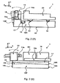
- a conventional machine tool 1 is shown in a perspective view in Fig. 1, in a side view Fig. 2(A) and in a front view in Fig. 2(B).
- the upper surface of a bed 10 of the machine tool 1 has a recess that forms a fluid channel 16 where fluid flows.
- the fluid is a coolant for cooling down a contact point between the machining tool (not shown) mounted on a tool spindle stock 20 and a workpiece (not shown) supported by a head stock 14 and a tail stock 15.
- the fluid is supplied to the contact point between the machining tool and the workpiece, drops into the fluid channel 16, is collected to a tank (not shown) and is resupplied to the contact point.
- the rigidity of the bed 10 is high. The reason is that deformation of the bed results from low rigidity so as to cause an error of the relative position between the workpiece and the machining tool, even if the machining tool on the tool spindle stock 20 is accurately controlled.
- a bed for a machine tool whose natural frequency becomes higher comprises a fluid channel crossing the bed and at least one reinforcement bridging the fluid channel.
- a conventional machine tool 1 is shown in Fig. 1 in a perspective view, Fig. 2(A) in a side view and Fig. 2(B) in a front view.
- a machine tool 1 comprises a bed 10, a head stock 14, a spindle 14a, a tail stock 15, a table 15a, a tool spindle stock 20, a plain guide 12, a V-shape guide 13, etc.
- the X, Y and Z-axes are right-angled to each other.
- the Y-axis is vertical.
- the X-axis is horizontal and corresponds to a rotational axis of a workpiece (not shown) supported between the spindle 14a and the tail stock 15.
- the Z-axis is horizontal and corresponds to a moving direction of a machining tool (not shown) perpendicular to the X-axis.
- the plain guide 12 and the V-shape guide 13 are fixed onto the bed 10 and guide the tool spindle stock 20 moving along the X-axis.
- the machining tool (not shown) is movably arranged on the tool spindle stock 20 along the Z-axis.
- Fluid (coolant, oil, etc.) is supplied to a contact point between the machining tool and the workpiece.
- the bed 10 has a fluid channel 16 crossing its top surface from one side 10R to the other side 10L in order to flow the fluid.
- the fluid channel 15 has openings 16R and 16L at the both sides 10L and 10R so that the fluid is led and collected to a tank (not shown) through the openings 16L and 16R. Then the fluid is resupplied to the contact point between the machining tool and the workpiece.
- the fluid channel 16 is formed by a combination of two slopes.
- a seam of the slopes is the highest point at the center of the fluid channel 16, and the each slope leans to each opening 16L and 16R of the lowest point respectively.
- On the right slope of the fluid channel 16 of Fig. 2(B) is an elongated fluid collecting pan 17 whose bottom leans to the right opening 16R.
- the fluid is supplied to the contact point, drops onto the pan 17, flows toward the right opening 16R and is collected to the tank from the opening 16R. (Of course, the fluid collecting pan 17 may be at the left slope.
- the fluid is collected from the left opening 16L.
- the fluid channel 16 is able to form another shape, for example the center need not be the highest point, or the opening of the lowest point could be present at only one side. Namely, the fluid channel 16 could have at least one opening 16L or 16R.
- the rigidity of the bed 10 is reduced so that the head stock 14, the spindle 14a, the tail stock 15 and the table 15a may vibrate toward and apart from the tool spindle stock 20, as shown in Fig. 2(A), so as to deteriorate the machining accuracy of the workpiece.
- the reduced rigidity may let the part vibrate in the direction of the overhanging so as to deteriorate the machining accuracy of the workpiece.
- a bed structure of first embodiment will be described with reference to Fig. 3(A).
- a pair of reinforcements 30 bridges the fluid channel 16 over its width Wm.
- the reinforcements are each comprised of a rigid element having ends fixed to the top of the bed at opposite sides of the fluid channel.
- the number of the reinforcements 30 is at least one, so one or a plurality of the reinforcement 30 bridges the fluid channel 16.
- Each reinforcement 30 is arranged not to interfere with the tool spindle stock 20 guided on the plain guide 12 and the V-shape guide 13 to move along the X-axis.
- the reinforcements 30 make the rigidity of the bed 10 higher so as to reduce the rotational vibration of the head stock 14, the tail stock 15 and the table 15a around X-axis shown in Fig. 2(A). Thus the machining accuracy of the workpiece becomes higher.
- a bed structure of a second embodiment will be described with reference to Fig. 3(B).
- a pair of reinforcements 30 bridges the fluid channel 16 over its width Wm at both sides 10L and 10R of the bed 10 where the openings 16L and 16R exist.
- the reinforcements are each comprised of a rigid element having ends fixed to the sides of the bed at opposite upper sides of the fluid channel.
- the number of the reinforcements 30 is at least one, so at least one of both sides 10L and 10R of the fluid channel 16 is bridged by the reinforcement 30.
- the reinforcements 30 may be designed favorably without restriction of their size, shape, etc, so long as they do not interfere with the tool spindle stock.
- the reinforcements 30 make the rigidity of the bed 10 higher so as to reduce the rotational vibration of the head stock 14, the tail stock 15 and the table 15a around the X-axis shown in Fig. 2(A). Thus the machining accuracy of the workpiece becomes higher.
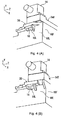
- Abed structure of third embodiment will be described with reference to Figs. 4(A) and 4(B).
- a head stock 14 and a head stock table 14T are mounted on the bed 10 adjacent to the opening 16L.
- a reinforcement 30 bridges the opening 16L of the fluid channel 16 and also supports the head stock 14 and the head stock table 14T which overhang the side 10L of the bed 10.
- the reinforcements are each comprised of a rigid element having ends fixed to the sides of the bed at opposite upper sides of the fluid channel.
- the reinforcement 30 and the bed 10 are connected by ribs so that the reinforcement 30 and the ribs favorably support the weight of the head stock 14 and the head stock table 14T overhanging from the bed 10.
- the reinforcement 30 makes the rigidity of the bed 10 higher so as to reduce the rotational vibration of the head stock 14 around the Z-axis shown in Fig. 2(B). Thus the machining accuracy of the workpiece becomes higher.
- Fig. 5(A) shows a simulation graph whose horizontal axis is a mode number and vertical axis is natural frequency, comparing the conventional art having no reinforcement with the embodiment having the reinforcement (the second embodiment) at every mode number.
- Fig. 5(A) also shows an explanatory drawing of the mode number at the bottom.
- the mode number is the number of nodes of a cantilever, wherein the first mode indicates a vibration with one node and the second mode indicates a vibration with two nodes.
- the bed 10 of the embodiment has a higher natural frequency than the conventional art.
- the natural frequency of the machine tool exists in a range of a frequency of vibrations caused by using the machining tool (for example, rotating a grinding wheel of a grinding machine)
- the bed 10 resonates because of the natural frequency so as to deteriorate the machining accuracy.
- the bed 10 of the embodiment makes the natural frequency of the machine tool 1 higher, the natural frequency is higher than the range of the vibration frequency of the machining tool. Therefore the vibration frequency of the machining tool does not correspond to the natural frequency of the machine tool 1 so as to improve the machining accuracy.
- Changing the range of using the machining tool should affect the machining accuracy because the machining tool directly contacts the workpiece. So changing the natural frequency of the machine tool 1 is preferable for higher machining accuracy. In addition, a higher natural frequency is preferable to a lower natural frequency. The reason is that the vibration frequency of the machining tool goes through the low frequency level during the transition from stop to the operating range of the machining tool.
- Fig. 5(B) shows a simulation graph whose horizontal axis is frequency [Hz:] and vertical axis is vibration amount [ ⁇ m/N].
- a dotted line identifies the bed of the conventional art having no reinforcement
- a solid line identifies the second embodiment having the reinforcement
- a chain line identifies the third embodiment having the modified reinforcement.
- the natural frequencies of the, second embodiment in comparison with the conventional art (the dotted line's peak 2a)
- the third embodiment the chain line's peak 2c
- the peaks 2a, 2b and 2c identify the natural frequencies corresponding to the second mode of the mode number explained in Fig. 5(A).
- a bed 10 for machine tool includes a fluid channel 16 crossing the bed 10 and at least one reinforcement 30 bridging the fluid channel 16.
Landscapes
- Engineering & Computer Science (AREA)
- Mechanical Engineering (AREA)
- Machine Tool Units (AREA)
Abstract
Description
- This invention relates to a bed for a machine tool, wherein the bed has a fluid channel.
- Metal working by a machine tool conventionally requires fluid, for example a coolant in order to cool down a contact point between a workpiece and the machining tool, oil in order to lubricate or cool down the machining tool, etc. The fluid is collected and resupplied by a circulatory conduit.
- A
conventional machine tool 1 is shown in a perspective view in Fig. 1, in a side view Fig. 2(A) and in a front view in Fig. 2(B). The upper surface of abed 10 of themachine tool 1 has a recess that forms afluid channel 16 where fluid flows. For example, the fluid is a coolant for cooling down a contact point between the machining tool (not shown) mounted on atool spindle stock 20 and a workpiece (not shown) supported by ahead stock 14 and atail stock 15. The fluid is supplied to the contact point between the machining tool and the workpiece, drops into thefluid channel 16, is collected to a tank (not shown) and is resupplied to the contact point. - It is preferable that the rigidity of the
bed 10 is high. The reason is that deformation of the bed results from low rigidity so as to cause an error of the relative position between the workpiece and the machining tool, even if the machining tool on thetool spindle stock 20 is accurately controlled. - However the presence of the
fluid channel 16 lowers the rigidity of thebed 10. That causes rotational vibration of thehead stock 14, thetail stock 15, the table 15a, etc. around the X-axis, as shown in Fig. 2(A). Thus there may occur fluctuation of the relative position between the workpiece and the machining tool so that the machining accuracy may be lower. Additionally, as shown in Fig. 2(B), because of recent requirements of downsizing, somemachine tools 1, have thehead stock 14, etc. overhanging theside 10L of thebed 10. Insuch machine tool 1, the rotational vibration of thehead stock 14, etc. around Z-axis may be increased because of the low rigidity of thebed 10, so that the machining accuracy may be lower. - In view of the foregoing, it is an object of the present invention to provide a bed for a machine tool whose rigidity becomes higher.
- In order to further the above and other objects, a bed for a machine tool whose natural frequency becomes higher comprises a fluid channel crossing the bed and at least one reinforcement bridging the fluid channel.
- Various other objects, features and many of the attendant advantages of the present invention will be readily appreciated as the same becomes better understood by reference to the following detailed description of the preferred embodiments when considered in connection with the accompanying drawings, in which:
- Fig. 1 is a perspective view of a bed for a machine tool of a conventional machine tool;
- Fig. 2(A) is a side view of the conventional machine tool;
- Fig. 2(B) is a front view of the conventional machine tool;
- Fig. 3(A) is a perspective view of a bed for a machine tool of a first embodiment of the present invention;
- Fig. 3(B) is a perspective view of a bed for a machine tool of a second embodiment of the present invention;
- Figs. 4(A) and 4(B) show explanatory drawings of a reinforcement of a third embodiment of the present invention; and
- Figs. 5(A) and 5(B) show explanatory drawings of effects of the embodiments.
- Embodiments of a bed for a machine tool related to the present invention will be described with reference to the figures.
- A
conventional machine tool 1 is shown in Fig. 1 in a perspective view, Fig. 2(A) in a side view and Fig. 2(B) in a front view. Amachine tool 1 comprises abed 10, ahead stock 14, aspindle 14a, atail stock 15, a table 15a, atool spindle stock 20, aplain guide 12, a V-shape guide 13, etc. The X, Y and Z-axes are right-angled to each other. The Y-axis is vertical. The X-axis is horizontal and corresponds to a rotational axis of a workpiece (not shown) supported between thespindle 14a and thetail stock 15. The Z-axis is horizontal and corresponds to a moving direction of a machining tool (not shown) perpendicular to the X-axis. Theplain guide 12 and the V-shape guide 13 are fixed onto thebed 10 and guide thetool spindle stock 20 moving along the X-axis. The machining tool (not shown) is movably arranged on thetool spindle stock 20 along the Z-axis. Fluid (coolant, oil, etc.) is supplied to a contact point between the machining tool and the workpiece. Thebed 10 has afluid channel 16 crossing its top surface from oneside 10R to theother side 10L in order to flow the fluid. Thefluid channel 15 hasopenings sides openings - As shown in Fig. 2(B), the
fluid channel 16 is formed by a combination of two slopes. A seam of the slopes is the highest point at the center of thefluid channel 16, and the each slope leans to each opening 16L and 16R of the lowest point respectively. On the right slope of thefluid channel 16 of Fig. 2(B) is an elongated fluid collectingpan 17 whose bottom leans to the right opening 16R. Thus the fluid is supplied to the contact point, drops onto thepan 17, flows toward the right opening 16R and is collected to the tank from the opening 16R. (Of course, the fluid collectingpan 17 may be at the left slope. In this case, the fluid is collected from the left opening 16L.) Thefluid channel 16 is able to form another shape, for example the center need not be the highest point, or the opening of the lowest point could be present at only one side. Namely, thefluid channel 16 could have at least one opening 16L or 16R. - In the
conventional machine tool 1, because of the presence of thefluid channel 16, the rigidity of thebed 10 is reduced so that thehead stock 14, thespindle 14a, thetail stock 15 and the table 15a may vibrate toward and apart from thetool spindle stock 20, as shown in Fig. 2(A), so as to deteriorate the machining accuracy of the workpiece. Also as shown in Fig. 2(B), where one part, for example thehead stock 14, etc., overhangs from theside 10L of thebed 10, the reduced rigidity may let the part vibrate in the direction of the overhanging so as to deteriorate the machining accuracy of the workpiece. - Hereinafter there will be described embodiments of a
bed 10 for amachine tool 1 related to the present invention which reduces the rotational vibration of Figs. 2(A) and 2(B). However, because the basic structure of the machine tool of the embodiments is similar to the conventional art of Fig. 1, the explanation of equipment arranged on the bed will be omitted. - A bed structure of first embodiment will be described with reference to Fig. 3(A). In the first embodiment, a pair of
reinforcements 30 bridges thefluid channel 16 over its width Wm. In this embodiment the reinforcements are each comprised of a rigid element having ends fixed to the top of the bed at opposite sides of the fluid channel. The number of thereinforcements 30 is at least one, so one or a plurality of thereinforcement 30 bridges thefluid channel 16. Eachreinforcement 30 is arranged not to interfere with thetool spindle stock 20 guided on theplain guide 12 and the V-shape guide 13 to move along the X-axis. Thereinforcements 30 make the rigidity of thebed 10 higher so as to reduce the rotational vibration of thehead stock 14, thetail stock 15 and the table 15a around X-axis shown in Fig. 2(A). Thus the machining accuracy of the workpiece becomes higher. - A bed structure of a second embodiment will be described with reference to Fig. 3(B). In the second embodiment, a pair of
reinforcements 30 bridges thefluid channel 16 over its width Wm at bothsides bed 10 where theopenings reinforcements 30 is at least one, so at least one of bothsides fluid channel 16 is bridged by thereinforcement 30. Thereinforcements 30 may be designed favorably without restriction of their size, shape, etc, so long as they do not interfere with the tool spindle stock. Thereinforcements 30 make the rigidity of thebed 10 higher so as to reduce the rotational vibration of thehead stock 14, thetail stock 15 and the table 15a around the X-axis shown in Fig. 2(A). Thus the machining accuracy of the workpiece becomes higher. - Abed structure of third embodiment will be described with reference to Figs. 4(A) and 4(B). A
head stock 14 and a head stock table 14T are mounted on thebed 10 adjacent to theopening 16L. Areinforcement 30 bridges theopening 16L of thefluid channel 16 and also supports thehead stock 14 and the head stock table 14T which overhang theside 10L of thebed 10. In this embodiment the reinforcements are each comprised of a rigid element having ends fixed to the sides of the bed at opposite upper sides of the fluid channel. Thereinforcement 30 and thebed 10 are connected by ribs so that thereinforcement 30 and the ribs favorably support the weight of thehead stock 14 and the head stock table 14T overhanging from thebed 10. Thereinforcement 30 makes the rigidity of thebed 10 higher so as to reduce the rotational vibration of thehead stock 14 around the Z-axis shown in Fig. 2(B). Thus the machining accuracy of the workpiece becomes higher. - Next, effects of the embodiments of the present invention will be described with reference to Figs. 5(A) and 5(B), compared to the conventional art. Fig. 5(A) shows a simulation graph whose horizontal axis is a mode number and vertical axis is natural frequency, comparing the conventional art having no reinforcement with the embodiment having the reinforcement (the second embodiment) at every mode number. Fig. 5(A) also shows an explanatory drawing of the mode number at the bottom. The mode number is the number of nodes of a cantilever, wherein the first mode indicates a vibration with one node and the second mode indicates a vibration with two nodes.
- As shown in the graph of Fig. 5(A), the
bed 10 of the embodiment has a higher natural frequency than the conventional art. Where the natural frequency of the machine tool exists in a range of a frequency of vibrations caused by using the machining tool (for example, rotating a grinding wheel of a grinding machine), thebed 10 resonates because of the natural frequency so as to deteriorate the machining accuracy. However, because thebed 10 of the embodiment makes the natural frequency of themachine tool 1 higher, the natural frequency is higher than the range of the vibration frequency of the machining tool. Therefore the vibration frequency of the machining tool does not correspond to the natural frequency of themachine tool 1 so as to improve the machining accuracy. - Changing the range of using the machining tool (e.g. the rotation range of the grinding wheel) should affect the machining accuracy because the machining tool directly contacts the workpiece. So changing the natural frequency of the
machine tool 1 is preferable for higher machining accuracy. In addition, a higher natural frequency is preferable to a lower natural frequency. The reason is that the vibration frequency of the machining tool goes through the low frequency level during the transition from stop to the operating range of the machining tool. - Fig. 5(B) shows a simulation graph whose horizontal axis is frequency [Hz:] and vertical axis is vibration amount [µm/N]. In Fig. 5(B), a dotted line identifies the bed of the conventional art having no reinforcement, a solid line identifies the second embodiment having the reinforcement and a chain line identifies the third embodiment having the modified reinforcement. As shown in the graph of Fig. 5(B), in comparison with the conventional art (the dotted line's
peak 2a), the natural frequencies of the, second embodiment (the solid line'speak 2b) and the third embodiment (the chain line'speak 2c) shift to higher frequencies and reduce their vibration amount. Thepeaks - Obviously, numerous modifications and variations of the present invention are possible in light of the above teachings. For example, the type of the
machine tool 1 and the shape, the size, the bridging position, the number and the material of the reinforcement(s) 30 may be changed from the above mentioned embodiments. It is thereby to be understood that within the scope of the appended claims, the present invention may be practiced otherwise than as specifically described herein. - A
bed 10 for machine tool includes afluid channel 16 crossing thebed 10 and at least onereinforcement 30 bridging thefluid channel 16. Thus the machining accuracy of a workpiece becomes higher.
Claims (5)
- A bed structure for a machine tool comprising:a bed; anda fluid channel crossing the bed to flow fluid; characterized in thatat least one reinforcement bridges the fluid channel.
- A bed structure for a machine tool to claim 1, wherein the reinforcement bridges an opening of the fluid channel at a side of the bed.
- A bed structure for a machine tool according to claim 2, wherein:a part is arranged on the bed and overhangs the side of the bed; andthe reinforcement supports weight of the part.
- A bed structure for a machine tool comprising:a bed having a natural frequency; anda fluid channel crossing the bed to flow fluid; characterized in thatmeans bridging the fluid channel increases the natural frequency of the bed.
- A bed structure for a machine tool comprising:a bed; anda fluid channel crossing a top surface of the bed to flow fluid; characterized in thatat least one rigid reinforcement bridges the fluid channel and is fixed to the bed at bothsides of the fluid channel adjacent the top surface.
Applications Claiming Priority (1)
| Application Number | Priority Date | Filing Date | Title |
|---|---|---|---|
| JP2005241181A JP4696779B2 (en) | 2005-08-23 | 2005-08-23 | Machine tool bed structure |
Publications (2)
| Publication Number | Publication Date |
|---|---|
| EP1757403A1 true EP1757403A1 (en) | 2007-02-28 |
| EP1757403B1 EP1757403B1 (en) | 2008-06-04 |
Family
ID=37013134
Family Applications (1)
| Application Number | Title | Priority Date | Filing Date |
|---|---|---|---|
| EP06118665A Ceased EP1757403B1 (en) | 2005-08-23 | 2006-08-09 | Bed structure for machine tool |
Country Status (4)
| Country | Link |
|---|---|
| US (1) | US7861627B2 (en) |
| EP (1) | EP1757403B1 (en) |
| JP (1) | JP4696779B2 (en) |
| DE (1) | DE602006001380D1 (en) |
Families Citing this family (7)
| Publication number | Priority date | Publication date | Assignee | Title |
|---|---|---|---|---|
| WO2010110030A1 (en) * | 2009-03-27 | 2010-09-30 | 村田機械株式会社 | Two-axis machine tool |
| JP5580021B2 (en) * | 2009-11-17 | 2014-08-27 | 三井精機工業株式会社 | Coolant discharge device for machine tool |
| CN102059636B (en) * | 2010-12-27 | 2013-04-03 | 东华大学 | Design method and structure of ultra high-speed grinder body |
| CN106181427A (en) * | 2016-08-24 | 2016-12-07 | 无锡市太湖同步带轮厂 | Lathe base |
| US11964353B2 (en) * | 2019-07-10 | 2024-04-23 | Leen David Steed | Machine debris clean out system |
| US20240189953A1 (en) | 2021-04-15 | 2024-06-13 | Dmg Mori Co., Ltd. | Machine tool |
| CN113478244B (en) * | 2021-08-09 | 2024-07-19 | 田原建川 | Intelligent floating hard rail sliding block using cooling cutting lubricating liquid |
Citations (2)
| Publication number | Priority date | Publication date | Assignee | Title |
|---|---|---|---|---|
| EP0358852A1 (en) * | 1988-08-16 | 1990-03-21 | Festo KG | Device for transporting a fluid |
| DE4326595A1 (en) * | 1993-08-07 | 1995-02-09 | Strausak Ag Maschinenfabrik Lo | Universal grinding station |
Family Cites Families (19)
| Publication number | Priority date | Publication date | Assignee | Title |
|---|---|---|---|---|
| US1096588A (en) * | 1914-03-04 | 1914-05-12 | Cincinnati Milling Machine Co | Chip-confining frame. |
| US1426496A (en) * | 1921-04-02 | 1922-08-22 | Cincinnati Bickford Tool Co | Center-drain turntable |
| US2482729A (en) * | 1943-12-02 | 1949-09-20 | Dzus William | Milling machine |
| US3195415A (en) * | 1962-09-14 | 1965-07-20 | Ray E Shorb | T-slot strainer accessory |
| US3793777A (en) * | 1972-05-22 | 1974-02-26 | Elb Schliff | Fluid-operated machine tool with means for effecting uniform expansion of its frame in response to heating by operating fluid |
| JPS61214929A (en) * | 1985-03-22 | 1986-09-24 | Mitsubishi Heavy Ind Ltd | Bed for machine tool |
| US5871130A (en) * | 1985-09-20 | 1999-02-16 | Jac Products, Inc. | Vehicle article carrier |
| DE4441253A1 (en) * | 1994-11-19 | 1996-05-23 | Hermle Berthold Maschf Ag | Machine tool, in particular drilling and milling machine |
| US5833103A (en) * | 1997-11-12 | 1998-11-10 | Jac Products, Inc. | Vehicle article carrier having single side releasable locking mechanism |
| DE60000169T2 (en) * | 2000-08-21 | 2002-10-31 | Ministero Dell' Universita' E Della Ricerca Scientifica E Tecnologica, Rom/Roma | High speed manufacturing unit for machining operations |
| JP2002127012A (en) * | 2000-10-26 | 2002-05-08 | Mitsubishi Heavy Ind Ltd | Grinder |
| JP3739300B2 (en) * | 2001-05-02 | 2006-01-25 | 株式会社牧野フライス製作所 | Machine Tools |
| DE10141865B4 (en) * | 2001-08-27 | 2006-02-02 | Deckel Maho Pfronten Gmbh | Program-controlled universal milling and drilling machine |
| US7104169B2 (en) * | 2002-10-17 | 2006-09-12 | Toyoda Koki Kabushiki Kaisha | Machine tool and bed structure thereof |
| DE10252824A1 (en) * | 2002-11-13 | 2004-06-03 | Deckel Maho Pfronten Gmbh | machine tool |
| US7503244B2 (en) * | 2003-06-17 | 2009-03-17 | Jtekt Corporation | Machine tool and bed thereof |
| JP4650923B2 (en) * | 2003-09-30 | 2011-03-16 | 株式会社森精機製作所 | Machine Tools |
| DE102004044098A1 (en) * | 2004-09-08 | 2006-03-23 | Chiron-Werke Gmbh & Co. Kg | Machine tool with a machine foot |
| DE202005001316U1 (en) * | 2005-01-26 | 2005-03-31 | Mann & Hummel Gmbh | Collecting trough for a machine tool |
-
2005
- 2005-08-23 JP JP2005241181A patent/JP4696779B2/en not_active Expired - Fee Related
-
2006
- 2006-08-09 US US11/500,970 patent/US7861627B2/en not_active Expired - Fee Related
- 2006-08-09 EP EP06118665A patent/EP1757403B1/en not_active Ceased
- 2006-08-09 DE DE602006001380T patent/DE602006001380D1/en active Active
Patent Citations (2)
| Publication number | Priority date | Publication date | Assignee | Title |
|---|---|---|---|---|
| EP0358852A1 (en) * | 1988-08-16 | 1990-03-21 | Festo KG | Device for transporting a fluid |
| DE4326595A1 (en) * | 1993-08-07 | 1995-02-09 | Strausak Ag Maschinenfabrik Lo | Universal grinding station |
Also Published As
| Publication number | Publication date |
|---|---|
| JP4696779B2 (en) | 2011-06-08 |
| US7861627B2 (en) | 2011-01-04 |
| EP1757403B1 (en) | 2008-06-04 |
| US20070062348A1 (en) | 2007-03-22 |
| DE602006001380D1 (en) | 2008-07-17 |
| JP2007054903A (en) | 2007-03-08 |
Similar Documents
| Publication | Publication Date | Title |
|---|---|---|
| US7959386B2 (en) | Splash guard of machine tool | |
| US6632054B2 (en) | Portal milling machine | |
| EP2301711A1 (en) | Machine tool | |
| EP1254740B1 (en) | Machine tool with chip collection means | |
| EP1757403B1 (en) | Bed structure for machine tool | |
| CN105773289B (en) | Five-shaft linkage numerical control machining center | |
| JP2014161969A (en) | Machine tool equipped with cover structure suitable for discharging chips | |
| CN102029403B (en) | Machine tool | |
| CN220128123U (en) | Horizontal drilling and tapping integrated machine | |
| CN208178952U (en) | A kind of saddle seat of numerically-controlled machine tool | |
| CN211889857U (en) | Machine bed and vertical machining center | |
| KR102801228B1 (en) | Slide cover structure of machine tools | |
| JP2007061998A (en) | Machine Tools | |
| JPH08206935A (en) | Bed of machine tool | |
| JP7546150B2 (en) | Machine Tools | |
| JP7116172B2 (en) | Machine Tools | |
| JPH04294946A (en) | Machine tool tool body form | |
| CN223903381U (en) | Machine tool saddle and machine tool | |
| JP3368584B2 (en) | Wire electric discharge machine | |
| CN215880710U (en) | Machine base and drilling and tapping center | |
| CN220761656U (en) | Main and auxiliary rail composite processing table | |
| CN213411259U (en) | Novel vertical machining center machine | |
| TWI840102B (en) | Working machinery | |
| JPH0536610Y2 (en) | ||
| CN220533252U (en) | Cornea shaping mirror processing machine tool |
Legal Events
| Date | Code | Title | Description |
|---|---|---|---|
| PUAI | Public reference made under article 153(3) epc to a published international application that has entered the european phase |
Free format text: ORIGINAL CODE: 0009012 |
|
| AK | Designated contracting states |
Kind code of ref document: A1 Designated state(s): AT BE BG CH CY CZ DE DK EE ES FI FR GB GR HU IE IS IT LI LT LU LV MC NL PL PT RO SE SI SK TR |
|
| AX | Request for extension of the european patent |
Extension state: AL BA HR MK YU |
|
| 17P | Request for examination filed |
Effective date: 20070430 |
|
| AKX | Designation fees paid |
Designated state(s): DE |
|
| GRAP | Despatch of communication of intention to grant a patent |
Free format text: ORIGINAL CODE: EPIDOSNIGR1 |
|
| RIN1 | Information on inventor provided before grant (corrected) |
Inventor name: SAITO, TOSHIYUKI Inventor name: DEGUCHI, SHINJI Inventor name: NAKAMURA, TERUHIKO Inventor name: MAKINO, NAOKI Inventor name: KATO, IKUYA Inventor name: IDO, MASAHIRO |
|
| GRAS | Grant fee paid |
Free format text: ORIGINAL CODE: EPIDOSNIGR3 |
|
| GRAA | (expected) grant |
Free format text: ORIGINAL CODE: 0009210 |
|
| AK | Designated contracting states |
Kind code of ref document: B1 Designated state(s): DE |
|
| REF | Corresponds to: |
Ref document number: 602006001380 Country of ref document: DE Date of ref document: 20080717 Kind code of ref document: P |
|
| PLBE | No opposition filed within time limit |
Free format text: ORIGINAL CODE: 0009261 |
|
| STAA | Information on the status of an ep patent application or granted ep patent |
Free format text: STATUS: NO OPPOSITION FILED WITHIN TIME LIMIT |
|
| 26N | No opposition filed |
Effective date: 20090305 |
|
| PGFP | Annual fee paid to national office [announced via postgrant information from national office to epo] |
Ref country code: DE Payment date: 20230627 Year of fee payment: 18 |
|
| REG | Reference to a national code |
Ref country code: DE Ref legal event code: R119 Ref document number: 602006001380 Country of ref document: DE |
|
| PG25 | Lapsed in a contracting state [announced via postgrant information from national office to epo] |
Ref country code: DE Free format text: LAPSE BECAUSE OF NON-PAYMENT OF DUE FEES Effective date: 20250301 |